design of a robust stair climbing compliant modular … of a robust stair climbing compliant modular...
TRANSCRIPT
Design of a Robust Stair Climbing Compliant Modular Robot to TackleOverhang on Stairs
Ajinkya Bhole1, Sri Harsha Turlapati1, Rajashekhar V. S 1, Jay Dixit1, Suril V. Shah2, Madhava Krishna K1
Abstract— This paper discusses the concept and parameterdesign of a Robust Stair Climbing Compliant Modular Robot,capable of tackling stairs with overhangs. Modifying the geome-try of the periphery of the wheels of our robot helps in tacklingoverhangs. Along with establishing a concept design, robustdesign parameters are set to minimize performance variation.The Grey-based Taguchi Method is adopted for providing anoptimal setting for the design parameters of the robot. Therobot prototype is shown to have successfully scaled stairsof varying dimensions, with overhang, thus corroborating theanalysis performed.
I. INTRODUCTION
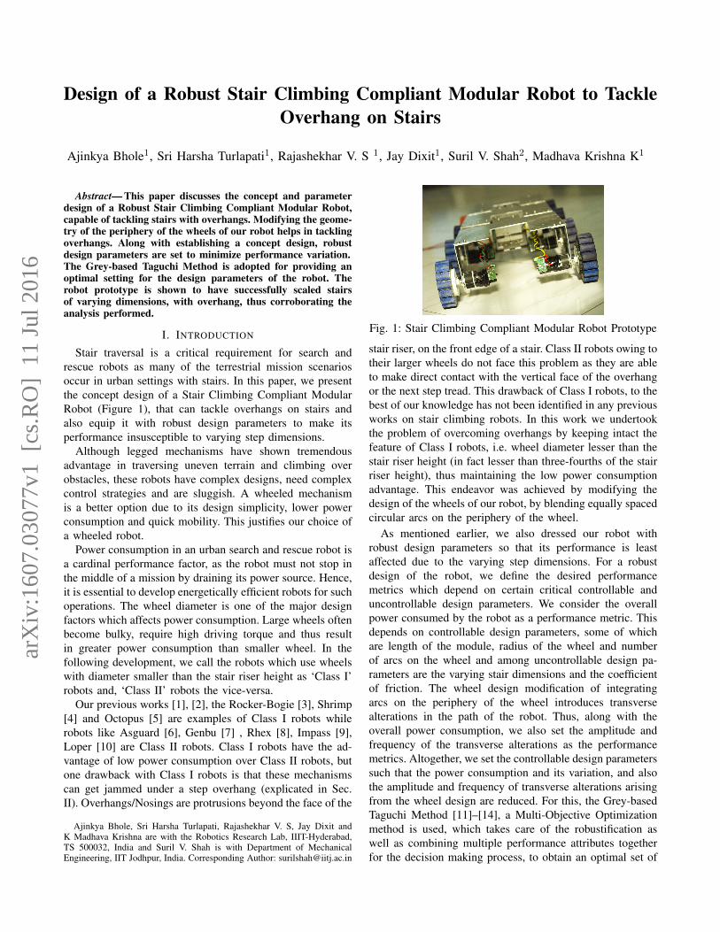
Stair traversal is a critical requirement for search andrescue robots as many of the terrestrial mission scenariosoccur in urban settings with stairs. In this paper, we presentthe concept design of a Stair Climbing Compliant ModularRobot (Figure 1), that can tackle overhangs on stairs andalso equip it with robust design parameters to make itsperformance insusceptible to varying step dimensions.
Although legged mechanisms have shown tremendousadvantage in traversing uneven terrain and climbing overobstacles, these robots have complex designs, need complexcontrol strategies and are sluggish. A wheeled mechanismis a better option due to its design simplicity, lower powerconsumption and quick mobility. This justifies our choice ofa wheeled robot.
Power consumption in an urban search and rescue robot isa cardinal performance factor, as the robot must not stop inthe middle of a mission by draining its power source. Hence,it is essential to develop energetically efficient robots for suchoperations. The wheel diameter is one of the major designfactors which affects power consumption. Large wheels oftenbecome bulky, require high driving torque and thus resultin greater power consumption than smaller wheel. In thefollowing development, we call the robots which use wheelswith diameter smaller than the stair riser height as ‘Class I’robots and, ‘Class II’ robots the vice-versa.
Our previous works [1], [2], the Rocker-Bogie [3], Shrimp[4] and Octopus [5] are examples of Class I robots whilerobots like Asguard [6], Genbu [7] , Rhex [8], Impass [9],Loper [10] are Class II robots. Class I robots have the ad-vantage of low power consumption over Class II robots, butone drawback with Class I robots is that these mechanismscan get jammed under a step overhang (explicated in Sec.II). Overhangs/Nosings are protrusions beyond the face of the
Ajinkya Bhole, Sri Harsha Turlapati, Rajashekhar V. S, Jay Dixit andK Madhava Krishna are with the Robotics Research Lab, IIIT-Hyderabad,TS 500032, India and Suril V. Shah is with Department of MechanicalEngineering, IIT Jodhpur, India. Corresponding Author: [email protected]
Fig. 1: Stair Climbing Compliant Modular Robot Prototype
stair riser, on the front edge of a stair. Class II robots owing totheir larger wheels do not face this problem as they are ableto make direct contact with the vertical face of the overhangor the next step tread. This drawback of Class I robots, to thebest of our knowledge has not been identified in any previousworks on stair climbing robots. In this work we undertookthe problem of overcoming overhangs by keeping intact thefeature of Class I robots, i.e. wheel diameter lesser than thestair riser height (in fact lesser than three-fourths of the stairriser height), thus maintaining the low power consumptionadvantage. This endeavor was achieved by modifying thedesign of the wheels of our robot, by blending equally spacedcircular arcs on the periphery of the wheel.
As mentioned earlier, we also dressed our robot withrobust design parameters so that its performance is leastaffected due to the varying step dimensions. For a robustdesign of the robot, we define the desired performancemetrics which depend on certain critical controllable anduncontrollable design parameters. We consider the overallpower consumed by the robot as a performance metric. Thisdepends on controllable design parameters, some of whichare length of the module, radius of the wheel and numberof arcs on the wheel and among uncontrollable design pa-rameters are the varying stair dimensions and the coefficientof friction. The wheel design modification of integratingarcs on the periphery of the wheel introduces transversealterations in the path of the robot. Thus, along with theoverall power consumption, we also set the amplitude andfrequency of the transverse alterations as the performancemetrics. Altogether, we set the controllable design parameterssuch that the power consumption and its variation, and alsothe amplitude and frequency of transverse alterations arisingfrom the wheel design are reduced. For this, the Grey-basedTaguchi Method [11]–[14], a Multi-Objective Optimizationmethod is used, which takes care of the robustification aswell as combining multiple performance attributes togetherfor the decision making process, to obtain an optimal set of
arX
iv:1
607.
0307
7v1
[cs
.RO
] 1
1 Ju
l 201
6

Fig. 2: Some eminent Class I robots which could get jammed under stair overhang
controllable design parameters.A body of work has been devoted to the concept design
of robots for stair climbing, but none of them to the bestof our knowledge, discussed specifically on the challenge oftackling overhangs, with a rigour like ours, thus providinga novelty to our work. Also, many previous works on stairclimbing robots have considered random stair dimensionsor dimensions which suit their robot designs, for theiranalysis. We have considered stair dimensions which followthe International Building Code (IBC) [15] and thus our workhas a high impact for rescue operations in urban settings.
The paper contributes as follows. Firstly, a solution toovercome overhang is proposed by modifying the wheeldesign. Secondly, it poses the parametric design of the robotas a multi-objective optimization problem. Since a functionalcharacterisation of the same is almost intractable, it makesuse of statistical methods [11]–[14] to solve for the optimaldesign. Setting the range for the design factors for thisoptimization problem forms a cardinal part of this work. Thisis a critical job, as setting an arbitrary range can lead to someconfigurations in which the robot can get stuck or even notclimb. With a careful analysis of all the design factor wehave logically backed every design factor’s range selection.As a consequence of this design procedure, a prototypewas fabricated and is shown to climb stairs and overhangsof varying dimensions many of them long and protruding.To the best of our knowledge, such a formal method ofposing wheel design to tackle overhangs as a statisticaloptimization formulation and the concomitant analysis anddetailed experimental verification does not appear in thesurveyed literature.
The paper is organised as follows: Section II discussesa concept design for tackling overhangs on stairs. A modelfor the parametric design of the robot is setup in SectionIII. Section IV presents design of experiments for evaluatingperformance metrics through Taguchi’s Orthogonal ArrayExperiments. Section V confirms the analysis performed bypractical experimentation. Finally, conclusions and scope offuture work are discussed in the Section VI.
II. CONCEPT DESIGN
The previous design of our stair climbing compliant mod-ular robot [2] with wheels of diameter lesser than the stairriser height got jammed under the overhangs.
Fig. 3: (a) Circular wheel failing to provide the desiredcounter-clockwise moment about axis of rotation for Module(b) Modified wheel design providing the desired counter-clockwise moment
As can be seen in Figure 3 (a), the first module getsjammed under the overhang as the external contact forceR obtained from the ground on the wheel fails to provide acounter-clockwise moment about the axis of rotation of themodule i.e. axis A. This prevents the module from foldinginwards thus disabling climbing. As can be seen in Figure 2,the same problem would be faced by some of the eminentClass I robots.
A counter-clockwise moment can be easily achieved bychanging some of the design parameters of the vehicle. Forexample, decreasing the length of the module or increasingthe radius of the wheel to such an extent that the contact forcestarts providing the desired counter-clockwise moment areviable options. But as discussed in the forthcoming SectionIII.C.b., in our case, the module length is constrained by acertain lower bound, exceeding which the module tips overwhile climbing. Increasing the radius of the wheel also isan unfavourable option, as this makes the robot quite bulky,increasing the power consumed. Similar design constraintscan also occur in other Class I robots.
The exercise of integrating knowledge of the geometryof stairs and mechanical interaction into a solution to thestair climbing problem usually comes in one of two flavors:we either use design (eg. [2]–[4]) or generate plans (e.g.,Rhex [8] uses a special algorithm). Shape is an easilyalterable design freedom with potential benefits both in termsof simplicity and robustness, hence we explored this. Wemodified the wheel design of our robot. As can be seen inFigure 3 (b), blending arcs on the circumference of the wheelchanges the direction of the resultant contact force obtainedfrom the overhang, providing a counter-clockwise momentabout the axis of rotation of the folding module.
As shown in the Figure 4, the wheel is designed by
10mm
Parent Circle (P)
Child Circle (C)
rprc
D
E
F
C
1 2 3 4
B
A
321 5
C
D
4 6 7 8
A
B
WheelWEIGHT:
A3
SHEET 1 OF 1SCALE:1:1
DWG NO.
TITLE:
REVISIONDO NOT SCALE DRAWING
MATERIAL:
DATESIGNATURENAME
DEBUR AND BREAK SHARP EDGES
FINISH:UNLESS OTHERWISE SPECIFIED:DIMENSIONS ARE IN MILLIMETERSSURFACE FINISH:TOLERANCES: LINEAR: ANGULAR:
Q.A
MFG
APPV'D
CHK'D
DRAWN
Fig. 4: Wheel De-sign
90 90
25 20
A B
p p
Wheel (a) Wheel (b)
DO NOT SCALE DRAWING
CompareeeSHEET 1 OF 1
UNLESS OTHERWISE SPECIFIED:
SCALE: 1:1 WEIGHT:
REVDWG. NO.
ASIZE
TITLE:
NAME DATE
COMMENTS:
Q.A.
MFG APPR.
ENG APPR.
CHECKED
DRAWN
FINISH
MATERIAL
INTERPRET GEOMETRICTOLERANCING PER:
DIMENSIONS ARE IN INCHESTOLERANCES:FRACTIONALANGULAR: MACH BEND TWO PLACE DECIMAL THREE PLACE DECIMAL
APPLICATION
USED ONNEXT ASSY
PROPRIETARY AND CONFIDENTIAL
THE INFORMATION CONTAINED IN THISDRAWING IS THE SOLE PROPERTY OF<INSERT COMPANY NAME HERE>. ANY REPRODUCTION IN PART OR AS A WHOLEWITHOUT THE WRITTEN PERMISSION OF<INSERT COMPANY NAME HERE> IS PROHIBITED.
5 4 3 2 1
Fig. 5: Child Circle size selection
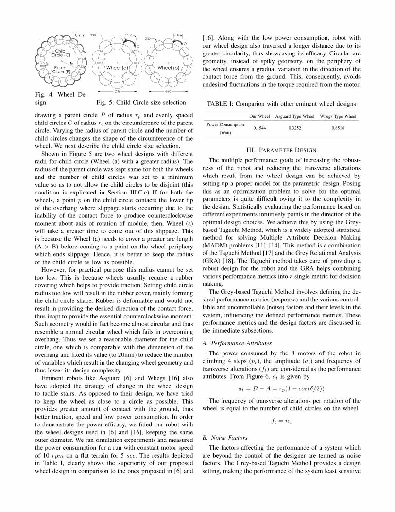
drawing a parent circle P of radius rp and evenly spacedchild circles C of radius rc on the circumference of the parentcircle. Varying the radius of parent circle and the number ofchild circles changes the shape of the circumference of thewheel. We next describe the child circle size selection.
Shown in Figure 5 are two wheel designs with differentradii for child circle (Wheel (a) with a greater radius). Theradius of the parent circle was kept same for both the wheelsand the number of child circles was set to a minimumvalue so as to not allow the child circles to be disjoint (thiscondition is explicated in Section III.C.c) If for both thewheels, a point p on the child circle contacts the lower tipof the overhang where slippage starts occurring due to theinability of the contact force to produce counterclockwisemoment about axis of rotation of module, then, Wheel (a)will take a greater time to come out of this slippage. Thisis because the Wheel (a) needs to cover a greater arc length(A > B) before coming to a point on the wheel peripherywhich ends slippage. Hence, it is better to keep the radiusof the child circle as low as possible.
However, for practical purpose this radius cannot be settoo low. This is because wheels usually require a rubbercovering which helps to provide traction. Setting child circleradius too low will result in the rubber cover, mainly formingthe child circle shape. Rubber is deformable and would notresult in providing the desired direction of the contact force,thus inapt to provide the essential counterclockwise moment.Such geometry would in fact become almost circular and thusresemble a normal circular wheel which fails in overcomingoverhang. Thus we set a reasonable diameter for the childcircle, one which is comparable with the dimension of theoverhang and fixed its value (to 20mm) to reduce the numberof variables which result in the changing wheel geometry andthus lower its design complexity.
Eminent robots like Asguard [6] and Whegs [16] alsohave adopted the strategy of change in the wheel designto tackle stairs. As opposed to their design, we have triedto keep the wheel as close to a circle as possible. Thisprovides greater amount of contact with the ground, thusbetter traction, speed and low power consumption. In orderto demonstrate the power efficacy, we fitted our robot withthe wheel designs used in [6] and [16], keeping the sameouter diameter. We ran simulation experiments and measuredthe power consumption for a run with constant motor speedof 10 rpm on a flat terrain for 5 sec. The results depictedin Table I, clearly shows the superiority of our proposedwheel design in comparison to the ones proposed in [6] and
[16]. Along with the low power consumption, robot withour wheel design also traversed a longer distance due to itsgreater circularity, thus showcasing its efficacy. Circular arcgeometry, instead of spiky geometry, on the periphery ofthe wheel ensures a gradual variation in the direction of thecontact force from the ground. This, consequently, avoidsundesired fluctuations in the torque required from the motor.
TABLE I: Comparion with other eminent wheel designs
Our Wheel Asguard Type Wheel Whegs Type Wheel
Power Consumption
(Watt)0.1544 0.3252 0.8516
III. PARAMETER DESIGN
The multiple performance goals of increasing the robust-ness of the robot and reducing the transverse alterationswhich result from the wheel design can be achieved bysetting up a proper model for the parametric design. Posingthis as an optimization problem to solve for the optimalparameters is quite difficult owing it to the complexity inthe design. Statistically evaluating the performance based ondifferent experiments intuitively points in the direction of theoptimal design choices. We achieve this by using the Grey-based Taguchi Method, which is a widely adopted statisticalmethod for solving Multiple Attribute Decision Making(MADM) problems [11]–[14]. This method is a combinationof the Taguchi Method [17] and the Grey Relational Analysis(GRA) [18]. The Taguchi method takes care of providing arobust design for the robot and the GRA helps combiningvarious performance metrics into a single metric for decisionmaking.
The Grey-based Taguchi Method involves defining the de-sired performance metrics (response) and the various control-lable and uncontrollable (noise) factors and their levels in thesystem, influencing the defined performance metrics. Theseperformance metrics and the design factors are discussed inthe immediate subsections.
A. Performance Attributes
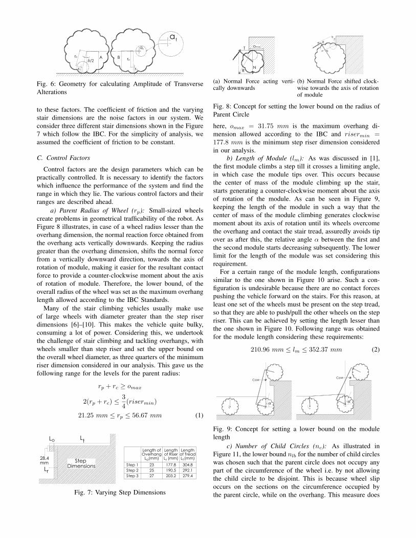
The power consumed by the 8 motors of the robot inclimbing 4 steps (pr), the amplitude (at) and frequency oftransverse alterations (ft) are considered as the performanceattributes. From Figure 6, at is given by
at = B −A = rp(1− cos(δ/2))
The frequency of transverse alterations per rotation of thewheel is equal to the number of child circles on the wheel.
ft = nc
B. Noise Factors
The factors affecting the performance of a system whichare beyond the control of the designer are termed as noisefactors. The Grey-based Taguchi Method provides a designsetting, making the performance of the system least sensitive
rp
rc
/2A Brp
rc
at
taD
C
B
A
B
C
D
12345678
8 7 6 5 4 3 2 1
E
F
E
F
1SHEET 1 OF 1
UNLESS OTHERWISE SPECIFIED:
SCALE: 1:1 WEIGHT:
REVDWG. NO.
CSIZE
TITLE:
NAME DATE
COMMENTS:
Q.A.
MFG APPR.
ENG APPR.
CHECKED
DRAWN
FINISH
MATERIAL
INTERPRET GEOMETRICTOLERANCING PER:
DIMENSIONS ARE IN INCHESTOLERANCES:FRACTIONALANGULAR: MACH BEND TWO PLACE DECIMAL THREE PLACE DECIMAL
APPLICATION
USED ONNEXT ASSY
PROPRIETARY AND CONFIDENTIAL
THE INFORMATION CONTAINED IN THISDRAWING IS THE SOLE PROPERTY OF<INSERT COMPANY NAME HERE>. ANY REPRODUCTION IN PART OR AS A WHOLEWITHOUT THE WRITTEN PERMISSION OF<INSERT COMPANY NAME HERE> IS PROHIBITED.
A
DO NOT SCALE DRAWING
Fig. 6: Geometry for calculating Amplitude of TransverseAlterations
to these factors. The coefficient of friction and the varyingstair dimensions are the noise factors in our system. Weconsider three different stair dimensions shown in the Figure7 which follow the IBC. For the simplicity of analysis, weassumed the coefficient of friction to be constant.
C. Control Factors
Control factors are the design parameters which can bepractically controlled. It is necessary to identify the factorswhich influence the performance of the system and find therange in which they lie. The various control factors and theirranges are described ahead.
a) Parent Radius of Wheel (rp): Small-sized wheelscreate problems in geometrical trafficability of the robot. AsFigure 8 illustrates, in case of a wheel radius lesser than theoverhang dimension, the normal reaction force obtained fromthe overhang acts vertically downwards. Keeping the radiusgreater than the overhang dimension, shifts the normal forcefrom a vertically downward direction, towards the axis ofrotation of module, making it easier for the resultant contactforce to provide a counter-clockwise moment about the axisof rotation of module. Therefore, the lower bound, of theoverall radius of the wheel was set as the maximum overhanglength allowed according to the IBC Standards.
Many of the stair climbing vehicles usually make useof large wheels with diameter greater than the step riserdimensions [6]–[10]. This makes the vehicle quite bulky,consuming a lot of power. Considering this, we undertookthe challenge of stair climbing and tackling overhangs, withwheels smaller than step riser and set the upper bound onthe overall wheel diameter, as three quarters of the minimumriser dimension considered in our analysis. This gave us thefollowing range for the levels for the parent radius:
rp + rc ≥ omax
2(rp + rc) ≤3
4(risermin)
21.25 mm ≤ rp ≤ 56.67 mm (1)
Step Dimensions
L
28.4mm
Lr
tLoD
C
B
AA
B
C
D
12345678
8 7 6 5 4 3 2 1
E
F
E
F
REV
Not
atio
nD
NotationSHEET 1 OF 1
UNLESS OTHERWISE SPECIFIED:
SCALE: 1:1 WEIGHT:
REVDWG. NO.
DSIZE
TITLE:
NAME DATE
COMMENTS:
Q.A.
MFG APPR.
ENG APPR.
CHECKED
DRAWN
FINISH
MATERIAL
INTERPRET GEOMETRICTOLERANCING PER:
DIMENSIONS ARE IN INCHESTOLERANCES:FRACTIONALANGULAR: MACH BEND TWO PLACE DECIMAL THREE PLACE DECIMAL
APPLICATION
USED ONNEXT ASSY
PROPRIETARY AND CONFIDENTIALTHE INFORMATION CONTAINED IN THISDRAWING IS THE SOLE PROPERTY OF<INSERT COMPANY NAME HERE>. ANY REPRODUCTION IN PART OR AS A WHOLEWITHOUT THE WRITTEN PERMISSION OF<INSERT COMPANY NAME HERE> IS PROHIBITED.
o r t
Length of Overhang
L (mm)
Length of Riser L (mm)
Length of Tread L (mm)
Step 1 23 177.8 304.8Step 2 25 190.5 292.1Step 3 27 203.2 279.4
DO NOT SCALE DRAWING
TableSHEET 1 OF 1
UNLESS OTHERWISE SPECIFIED:
SCALE: 1:1 WEIGHT:
REVDWG. NO.
ASIZE
TITLE:
NAME DATE
COMMENTS:
Q.A.
MFG APPR.
ENG APPR.
CHECKED
DRAWN
FINISH
MATERIAL
INTERPRET GEOMETRICTOLERANCING PER:
DIMENSIONS ARE IN INCHESTOLERANCES:FRACTIONALANGULAR: MACH BEND TWO PLACE DECIMAL THREE PLACE DECIMAL
APPLICATION
USED ONNEXT ASSY
PROPRIETARY AND CONFIDENTIALTHE INFORMATION CONTAINED IN THISDRAWING IS THE SOLE PROPERTY OF<INSERT COMPANY NAME HERE>. ANY REPRODUCTION IN PART OR AS A WHOLEWITHOUT THE WRITTEN PERMISSION OF<INSERT COMPANY NAME HERE> IS PROHIBITED.
5 4 3 2 1
Fig. 7: Varying Step Dimensions
N
T
R
omax
D
C
B
A
B
C
D
12345678
8 7 6 5 4 3 2 1
E
F
E
F
1SHEET 1 OF 1
UNLESS OTHERWISE SPECIFIED:
SCALE: 1:1 WEIGHT:
REVDWG. NO.
CSIZE
TITLE:
NAME DATE
COMMENTS:
Q.A.
MFG APPR.
ENG APPR.
CHECKED
DRAWN
FINISH
MATERIAL
INTERPRET GEOMETRICTOLERANCING PER:
DIMENSIONS ARE IN INCHESTOLERANCES:FRACTIONALANGULAR: MACH BEND TWO PLACE DECIMAL THREE PLACE DECIMAL
APPLICATION
USED ONNEXT ASSY
PROPRIETARY AND CONFIDENTIALTHE INFORMATION CONTAINED IN THISDRAWING IS THE SOLE PROPERTY OF<INSERT COMPANY NAME HERE>. ANY REPRODUCTION IN PART OR AS A WHOLEWITHOUT THE WRITTEN PERMISSION OF<INSERT COMPANY NAME HERE> IS PROHIBITED.
A
DO NOT SCALE DRAWING
(a) Normal Force acting verti-cally downwards
N
TR
D
C
B
A
B
C
D
12345678
8 7 6 5 4 3 2 1
E
F
E
F
2SHEET 1 OF 1
UNLESS OTHERWISE SPECIFIED:
SCALE: 1:1 WEIGHT:
REVDWG. NO.
CSIZE
TITLE:
NAME DATE
COMMENTS:
Q.A.
MFG APPR.
ENG APPR.
CHECKED
DRAWN
FINISH
MATERIAL
INTERPRET GEOMETRICTOLERANCING PER:
DIMENSIONS ARE IN INCHESTOLERANCES:FRACTIONALANGULAR: MACH BEND TWO PLACE DECIMAL THREE PLACE DECIMAL
APPLICATION
USED ONNEXT ASSY
PROPRIETARY AND CONFIDENTIALTHE INFORMATION CONTAINED IN THISDRAWING IS THE SOLE PROPERTY OF<INSERT COMPANY NAME HERE>. ANY REPRODUCTION IN PART OR AS A WHOLEWITHOUT THE WRITTEN PERMISSION OF<INSERT COMPANY NAME HERE> IS PROHIBITED.
A
DO NOT SCALE DRAWING
(b) Normal Force shifted clock-wise towards the axis of rotationof module
Fig. 8: Concept for setting the lower bound on the radius ofParent Circle
here, omax = 31.75 mm is the maximum overhang di-mension allowed according to the IBC and risermin =177.8 mm is the minimum step riser dimension consideredin our analysis.
b) Length of Module (lm): As was discussed in [1],the first module climbs a step till it crosses a limiting angle,in which case the module tips over. This occurs becausethe center of mass of the module climbing up the stair,starts generating a counter-clockwise moment about the axisof rotation of the module. As can be seen in Figure 9,keeping the length of the module in such a way that thecenter of mass of the module climbing generates clockwisemoment about its axis of rotation until its wheels overcomethe overhang and contact the stair tread, assuredly avoids tipover as after this, the relative angle α between the first andthe second module starts decreasing subsequently. The lowerlimit for the length of the module was set considering thisrequirement.
For a certain range of the module length, configurationssimilar to the one shown in Figure 10 arise. Such a con-figuration is undesirable because there are no contact forcespushing the vehicle forward on the stairs. For this reason, atleast one set of the wheels must be present on the step tread,so that they are able to push/pull the other wheels on the stepriser. This can be achieved by setting the length lesser thanthe one shown in Figure 10. Following range was obtainedfor the module length considering these requirements:
210.96 mm ≤ lm ≤ 352.37 mm (2)
CoMD
C
B
AA
B
C
D
12345678
8 7 6 5 4 3 2 1
E
F
E
F
REV
1D
1SHEET 1 OF 1
UNLESS OTHERWISE SPECIFIED:
SCALE: 1:1 WEIGHT:
REVDWG. NO.
DSIZE
TITLE:
NAME DATE
COMMENTS:
Q.A.
MFG APPR.
ENG APPR.
CHECKED
DRAWN
FINISH
MATERIAL
INTERPRET GEOMETRICTOLERANCING PER:
DIMENSIONS ARE IN INCHESTOLERANCES:FRACTIONALANGULAR: MACH BEND TWO PLACE DECIMAL THREE PLACE DECIMAL
APPLICATION
USED ONNEXT ASSY
PROPRIETARY AND CONFIDENTIALTHE INFORMATION CONTAINED IN THISDRAWING IS THE SOLE PROPERTY OF<INSERT COMPANY NAME HERE>. ANY REPRODUCTION IN PART OR AS A WHOLEWITHOUT THE WRITTEN PERMISSION OF<INSERT COMPANY NAME HERE> IS PROHIBITED.
CoM
'
D
C
B
AA
B
C
D
12345678
8 7 6 5 4 3 2 1
E
F
E
F
REV
1D
1SHEET 1 OF 1
UNLESS OTHERWISE SPECIFIED:
SCALE: 1:1 WEIGHT:
REVDWG. NO.
DSIZE
TITLE:
NAME DATE
COMMENTS:
Q.A.
MFG APPR.
ENG APPR.
CHECKED
DRAWN
FINISH
MATERIAL
INTERPRET GEOMETRICTOLERANCING PER:
DIMENSIONS ARE IN INCHESTOLERANCES:FRACTIONALANGULAR: MACH BEND TWO PLACE DECIMAL THREE PLACE DECIMAL
APPLICATION
USED ONNEXT ASSY
PROPRIETARY AND CONFIDENTIALTHE INFORMATION CONTAINED IN THISDRAWING IS THE SOLE PROPERTY OF<INSERT COMPANY NAME HERE>. ANY REPRODUCTION IN PART OR AS A WHOLEWITHOUT THE WRITTEN PERMISSION OF<INSERT COMPANY NAME HERE> IS PROHIBITED.
Fig. 9: Concept for setting a lower bound on the modulelength
c) Number of Child Circles (nc): As illustrated inFigure 11, the lower bound nlb for the number of child circleswas chosen such that the parent circle does not occupy anypart of the circumference of the wheel i.e. by not allowingthe child circle to be disjoint. This is because wheel slipoccurs on the sections on the circumference occupied bythe parent circle, while on the overhang. This measure does

not completely cancel the slippage but reduces it. Reducingslip is important since having repeated slipping as the robotclimbs stairs is going to cause more energy consumption.The condition for lower bound can be given as follows:
№ докум. Подп. ДатаИнв
. № п
одл.
Под
п. и
дат
аВз
ам. и
нв. №
Инв
. № д
убл.
Под
п. и
дат
а
Копировал
Лист
Формат А3Изм. Лист
Fig. 10: Concept for set-ting an upper bound on themodule length
ab
Slip occurs in these sections of wheel
DO NOT SCALE DRAWING
MinSHEET 1 OF 1
UNLESS OTHERWISE SPECIFIED:
SCALE: 1:1 WEIGHT:
REVDWG. NO.
ASIZE
TITLE:
NAME DATE
COMMENTS:
Q.A.
MFG APPR.
ENG APPR.
CHECKED
DRAWN
FINISH
MATERIAL
INTERPRET GEOMETRICTOLERANCING PER:
DIMENSIONS ARE IN INCHESTOLERANCES:FRACTIONALANGULAR: MACH BEND TWO PLACE DECIMAL THREE PLACE DECIMAL
APPLICATION
USED ONNEXT ASSY
PROPRIETARY AND CONFIDENTIALTHE INFORMATION CONTAINED IN THISDRAWING IS THE SOLE PROPERTY OF<INSERT COMPANY NAME HERE>. ANY REPRODUCTION IN PART OR AS A WHOLEWITHOUT THE WRITTEN PERMISSION OF<INSERT COMPANY NAME HERE> IS PROHIBITED.
5 4 3 2 1
Fig. 11: Concept for settinga lower bound on the num-ber of child circles
nlb = dxe s.t. x(2rc) = 2πrp
Figure 12 depicts how as nc increases, the normal reac-tion generated moment gradually becomes clockwise frombeing counter-clockwise. The supremum for the number ofchild circles nup was chosen, such that the normal reactionobtained from the overhang generates a counter-clockwisemoment about the axis of rotation of the module as canbe seen in Figure 13. This assures that even with minimalfriction coefficient, the resultant contact force R generates acounter-clockwise moment. These conditions are containedin the following optimization:
Maximize nup
Subject to
(i) (φ1, φ2, φ3, φ4, δ) ∈ R(ii) (nup, p) ∈ Z+
(iii) rp cos(φ1) + rc = rp cos(φ1 + pδ)+
rc cos(φ1 + pδ − φ2)(iv) rp sin(φ1 ± δ) + rc ≤ rp cos(φ1) + rc
(v) rp sin(φ1 + (p− 1)δ) + rc =
rp sin(φ1 + pδ) + rc sin(φ1 + pδ − φ2)
(vi) −(δ2
)< φ1 ≤
(δ2
)(vii) 0 ≤ φ2 ≤
(δ2
)+ sin−1
(rp sin( δ2 )rc
)(viii) p ≤
⌈(nup4
)⌉(ix) φ4 ≤ φ3
as shown in Figure 13, φ1 is the angle made with thehorizontal by the line joining the center of climbing wheeland the center of its child circle touching the face of theriser. φ2 is the angle between the line joining the lower tipof the overhang with the center of the child circle climbingthe overhang and the line joining the center of the samechild circle with the center of the parent circle. φ3 is theangle made by the line joining the center of the secondwheel on the ground and the lower tip of the overhang withthe horizontal. φ4 is the angle made by the normal reactionforce obtained from the overhang with the horizontal. δ is the
N
T
R
Number of Child Circles=20+
D
C
B
AA
B
C
D
12345678
8 7 6 5 4 3 2 1
E
F
E
F
REV
1D
1SHEET 1 OF 1
UNLESS OTHERWISE SPECIFIED:
SCALE: 1:1 WEIGHT:
REVDWG. NO.
DSIZE
TITLE:
NAME DATE
COMMENTS:
Q.A.
MFG APPR.
ENG APPR.
CHECKED
DRAWN
FINISH
MATERIAL
INTERPRET GEOMETRICTOLERANCING PER:
DIMENSIONS ARE IN INCHESTOLERANCES:FRACTIONALANGULAR: MACH BEND TWO PLACE DECIMAL THREE PLACE DECIMAL
APPLICATION
USED ONNEXT ASSY
PROPRIETARY AND CONFIDENTIALTHE INFORMATION CONTAINED IN THISDRAWING IS THE SOLE PROPERTY OF<INSERT COMPANY NAME HERE>. ANY REPRODUCTION IN PART OR AS A WHOLEWITHOUT THE WRITTEN PERMISSION OF<INSERT COMPANY NAME HERE> IS PROHIBITED.
N
T
R
Number of Child Circles=21-
D
C
B
AA
B
C
D
12345678
8 7 6 5 4 3 2 1
E
F
E
F
REV
1D
1SHEET 1 OF 1
UNLESS OTHERWISE SPECIFIED:
SCALE: 1:1 WEIGHT:
REVDWG. NO.
DSIZE
TITLE:
NAME DATE
COMMENTS:
Q.A.
MFG APPR.
ENG APPR.
CHECKED
DRAWN
FINISH
MATERIAL
INTERPRET GEOMETRICTOLERANCING PER:
DIMENSIONS ARE IN INCHESTOLERANCES:FRACTIONALANGULAR: MACH BEND TWO PLACE DECIMAL THREE PLACE DECIMAL
APPLICATION
USED ONNEXT ASSY
PROPRIETARY AND CONFIDENTIALTHE INFORMATION CONTAINED IN THISDRAWING IS THE SOLE PROPERTY OF<INSERT COMPANY NAME HERE>. ANY REPRODUCTION IN PART OR AS A WHOLEWITHOUT THE WRITTEN PERMISSION OF<INSERT COMPANY NAME HERE> IS PROHIBITED.
Fig. 12: Concept for setting an upper bound on the numberof child circles
Fig. 13: Geometry for setting an upper bound on the numberof child circles
angle inscribed by the lines joining the center of the wheeland any two consecutive child circles. p is the number ofangles, δ, inscribed by the lines joining the center of theparent circle and the centers of the child circle touching theface of the riser and the child circle touching the lowertip of the overhang. The constraints (i) − (ii) representthe domain of the variables, (iii) − (v) are the geometricalconstraints, (vi) − (viii) contain the range of the variablesand the constraint (ix) ensures that the normal reactionforce generates the desirable counter-clockwise moment.Considering these bounds, the following range was obtainedfor the number of child circles:
16 ≤ nc ≤ 20 (3)
For the simplicity of the analysis, the control variables,clearance c between the ground and the module link and thestiffness values of the springs at the joints were kept constant.The clearance c, for ensuring geometrical trafficability, wasset, considering that the clearance in maximum when thewheel size is minimum and the module link length ismaximum with an additional safety margin [1].
The stiffness values for the springs at the joints, for allpossible combinations of the control factors were calculatedusing the method used in [2] and a mean value for allwas considered for our analysis. Following are the valuesconsidered for the clearance and the spring stiffness at thejoints:• c = 100 mm• k+1 = 74.47 Nmm/deg k−1 = 67.56 Nmm/deg• k+2 = 48.89 Nmm/deg k−2 = 57.61 Nmm/deg
where, k+i and k−i are the stiffness values of the springs at theith joint opposing the counter-clockwise and the clockwisemoments respectively.
Three levels are set for each control parameter taking intoconsideration the equations (1) - (3). The levels, Level 1,Level 2 and Level 3, respectively set for the Module lengthare 240 mm, 260 mm and 280 mm, that for Radius of theParent Circle are 40 mm, 45 mm and 50 mm, and finally

TABLE II: Orthogonal Array L9(33) experiments and their results, Grey Relational Coefficients and Grey Grades
RunNo.
A B CPower Required to
Climb 4 Steps (Watt)Amplitude
(mm)Frequency Grey Relational Coefficients
GreyRelational Grade
Rank
pr1 pr2 pr3 S/N Ratio Power Amplitude Frequency
1 1 1 1 4.02 4.07 5.19 -12.98 0.76 16 0.33 0.45 0.86 0.59 52 1 2 2 3.12 3.47 3.35 -10.43 0.68 18 0.67 0.55 0.79 0.57 73 1 3 3 3.49 3.87 3.79 -11.42 0.61 20 0.48 0.65 0.72 0.49 84 2 1 2 2.96 2.90 3.52 -9.95 0.60 18 0.83 0.67 0.71 0.66 35 2 2 3 2.99 2.99 3.08 -9.61 0.55 20 1 0.79 0.64 0.70 26 2 3 1 3.57 3.36 3.61 -10.93 0.96 16 0.56 0.33 1 0.63 47 3 1 3 4.28 3.95 3.70 -12.01 0.49 20 0.41 1 0.55 0.58 68 3 2 1 3.33 2.90 3.44 -10.19 0.86 16 0.74 0.38 0.94 0.70 19 3 3 2 3.96 3.41 4.15 -11.72 0.75 18 0.44 0.46 0.86 0.47 9
Legend: A: Levels of Module Length; B:Levels of Radius of Parent Circle; C:Levels of Number of Child Circles; pri is the power consumedby robot on the ith stair dimension
for the Number of Child Circles are 16, 18 and 20.
IV. DESIGN OF EXPERIMENTS
An all-inclusive experimentation of the control and noisefactor levels under study would have required 81 exper-iments. Taguchi′s Orthogonal Array (OA) [17] providesa condensed set of experiments, which are balanced toensure that all levels of factors are considered equallyand can be evaluated independently of each other. Basedon the number of parameters and their levels, the presentexperimentation was designed as per Taguchi′s L9(33) OA.It is quite time consuming, tedious and uneconomical toconduct physical experiments for all the combinations inthe OA. For this reason, we simulated our experiments inSolidWorks Motion Analysis, which is a robust physics-based solver. Similar approach of using simulation methodsin Taguchi’s Method can be seen in the references [19]–[21]. The subsections ahead describe the experiments andthe analysis performed on the experimental results.
A. Performance Metrics and their Data Collection
Robustness can be achieved by identifying control factorswhich reduce variability in a product/process, by minimizingthe effects of uncontrollable factors (noise factors). Noisefactors cannot be controlled during product use, but can becontrolled during experimentation. In a Taguchi designedexperiment, noise factors are manipulated to force variabilityto occur and from the results, identify optimal control factorsettings that make the process or product robust, or resistantto variation from the noise factors. Here, we vary the stairdimensions to force variability in the performance metrics.
The performance values collected from each run in the OAare tabulated in Table II. The Signal to Noise ratio (S/N),which reflects the ability of the system to perform well in thepresence of noise factors, is considered as the metric for thepower consumption attribute (S/N ratio is not required forthe Amplitude and Frequency attributes as they do not changewith the varying stair dimensions). As we are interestedin minimizing the power required, the “smaller-the-better”formula for S/N ratio given ahead is used
S/N ratio = η = −10 log10
[1
n
n∑i=1
(pri )2
]
TABLE III: Influence of Control Parameters on Grey Rela-tional Grade
Control
Parameter
Average Grey
Relational Grade by factor level
Level 1 Level 2 Level 3
Module Length 0.554162 0.668827* 0.587269
Radius of Parent Circle 0.615386 0.664180* 0.530693
Number of Child Circles 0.646039* 0.570653 0.593566
Optimal levels are indicated by symbol *
where, η denotes the S/N ratio calculated from the obtainedpri ’s which are the power consumption values from the ith
run in the OA and n is the number of times an experimentin the OA is repeated, i.e. the levels of noise factors, whichis three here.
B. Multi-Attribute Decision Making Method
Grey Relational Analysis (GRA) [18], a multi-attributedecision making technique is used to obtain the optimumset of various input parameters for the best performancecharacteristics. GRA firstly translates performance of allalternatives into a comparability sequence, a normalized datasequence between 0 and 1. Following the normalization,Grey relational coefficients (GRC) are calculated to expressthe relationship between the ideal and normalized data se-quence. A distinguishing coefficient is used to expand orcompress the range of the GRC. We calculated the GRCconsidering a distinguishing coefficient of 0.5 and the greyrelational grade for each combination of the control factorsin the Orthogonal Array was obtained by equal weighing oftheir GRC. The experiments were then ranked according totheir grey relational grades. Table II tabulates these results.
The influence of each control parameter on the GreyRelational Grade is presented in Table III, providing thefollowing optimal setting:
• Module Length = 260 mm,• Radius of Parent Circle = 45 mm and• Number of Child Circles = 16

TABLE IV: Analysis of Variance
Module
Length
Radius of
Parent Circle
Number of
Child CirclesError
Sum of
Squares0.020896 0.027373 0.008962 0.001618
F-test 12.91703 16.9208 5.539721
Percentage
Contribution35.50825 46.5144 15.2284 2.748948
C. Explanation of the Grey Relational Analysis Results
In all our simulation experiments, the angular velocityof all the wheels was kept constant. Therefore the powerconsumed by the robot is in proportion to the torque providedby the motors. As the wheel radius increases, the requireddriving torque also increases, thus increasing the powerconsumption. According to this argument, the minimumradius of the parent circle i.e. 40 mm should have been theoptimal setting. But we also need to take into considerationthe fact that as we go on decreasing the radius of the parentcircle, it becomes more difficult for the contact force on thewheel to provide a counter-clockwise moment about the axisof rotation of the module while overcoming the overhang.Hence, neither the least and nor the largest, but the nominallevel of the parameter performed optimally. Same was thecase with the module length. Increasing the length of themodule results in configurations which enable more numberof wheels to be in contact with the step tread providing abetter pushing and pulling force against the step risers on thewheels climbing the risers. But, at the same time, increasein the module length also results in an increased powerconsumption. Thus a nominal value for the module lengthresulted as the optimal setting. As the number of child circlesdecreases, the normal force obtained from the overhanggets directed farther away from the axis of rotation of themodule thus making it easier for the module to overcomethe overhang. Hence, the least value for the number of childcircles resulted in the optimal performance.
D. Analysis of Variance
The variability in the response variable, amongst differentfactors is decomposed using a statistical tool, Analysis ofVariance (ANOVA) [22]. The F-test [22] was used to studythe statistically significant control factors in our analysis. Theresults of the test are presented in Table IV, and indicatethat the Radius of the Parent Circle and the Length of theModule play a statistically significant role in the performancemeasure of the vehicle.
E. Prediction of Grey Relational Grade
The Grey Relational Grade can be predicted for theoptimal setting using the following equation
γp = γm +
n∑i=1
(γm − γi) (4)
where, γp is the predicted Grey Relational Grade for theoptimal setting, γm is the mean Grey Relational Grade, n
TABLE V: Optimal Setting Confirmation
Best OAExpt.
Optimal Setting
Prediction SimulationLevel A3B2C1 A2B2C1 A2B2C1
Power ConsumptionS/N Ratio
-10.1992 -9.4244
Amplitude 0.864662 0.864662Frequency 16 16Grey RelationalGrade
0.709478 0.729588 0.795383
is the number of statistically significant factors affecting theperformance and γi is the maximum average Grey RelationalGrade of a level for the ith statistically significant factor. Theapplication of this to our case is presented in the immediatesubsection.
F. Confirmation in Simulation
A simulation experiment was performed at the optimal set-ting of the control factors and its calculated Grey RelationalGrade was compared with the Predicted Grey RelationalGrade, the results of which are tabulated in the Table V.Its closeness to the predicted grade, successfully validatesour analysis.
V. CONFIRMATION IN EXPERIMENT
A robot prototype with the set of optimal design param-eters obtained from the proposed framework was manufac-tured. The material of choice for the chassis was aluminiumto cater to low weight and the wheels were 3D printed.The wheels were rubber padded for improved traction whileclimbing. Compliance was added by attaching a set of torsionsprings at each module joint. The motors were chosen suchthat they provide enough torque to achieve the desiredmoments for the modules to fold with respect to each otherand to carry the robot’s body upward to climb upstairs.
Fig. 14: The different wheels experimented with to checkclimbing ability
The robot equipped with a normal circular wheel withsmooth rubber padding (Figure 14 (a)) failed to climb thestairs with overhang, as shown in Figure 15 (a). Accordingto the reasoning provided in Section II, the robot fitted withwheels with low child circle radius (Figure 14 (b)) also kepton slipping at the overhang, as the rubber gets deformedand fails to provide the desired counter-clockwise moment.Figure 15 (b) shows the modified wheel (Figure 14 (c))overcoming an overhang, thus validating our concept design.The robot, without getting jammed under the overhang orgetting stuck in any configuration (Figure 16), successfullyclimbed the stair dimensions considered in our analysis, as
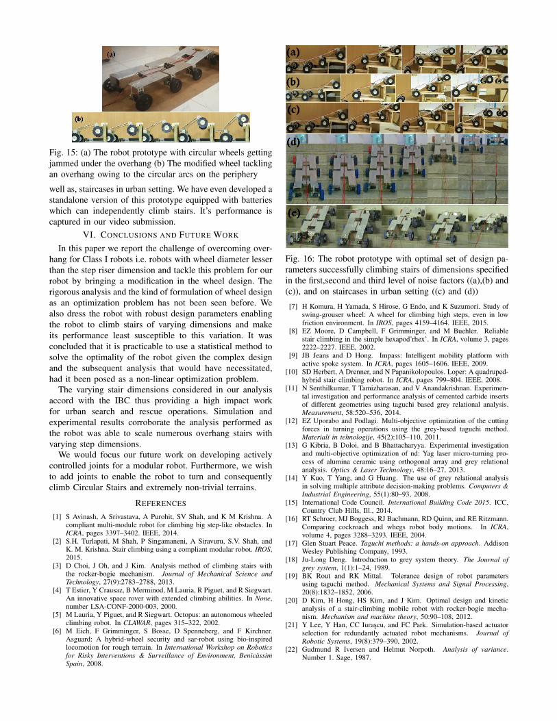
Fig. 15: (a) The robot prototype with circular wheels gettingjammed under the overhang (b) The modified wheel tacklingan overhang owing to the circular arcs on the periphery
well as, staircases in urban setting. We have even developed astandalone version of this prototype equipped with batterieswhich can independently climb stairs. It’s performance iscaptured in our video submission.
VI. CONCLUSIONS AND FUTURE WORK
In this paper we report the challenge of overcoming over-hang for Class I robots i.e. robots with wheel diameter lesserthan the step riser dimension and tackle this problem for ourrobot by bringing a modification in the wheel design. Therigorous analysis and the kind of formulation of wheel designas an optimization problem has not been seen before. Wealso dress the robot with robust design parameters enablingthe robot to climb stairs of varying dimensions and makeits performance least susceptible to this variation. It wasconcluded that it is practicable to use a statistical method tosolve the optimality of the robot given the complex designand the subsequent analysis that would have necessitated,had it been posed as a non-linear optimization problem.
The varying stair dimensions considered in our analysisaccord with the IBC thus providing a high impact workfor urban search and rescue operations. Simulation andexperimental results corroborate the analysis performed asthe robot was able to scale numerous overhang stairs withvarying step dimensions.
We would focus our future work on developing activelycontrolled joints for a modular robot. Furthermore, we wishto add joints to enable the robot to turn and consequentlyclimb Circular Stairs and extremely non-trivial terrains.
REFERENCES
[1] S Avinash, A Srivastava, A Purohit, SV Shah, and K M Krishna. Acompliant multi-module robot for climbing big step-like obstacles. InICRA, pages 3397–3402. IEEE, 2014.
[2] S.H. Turlapati, M Shah, P Singamaneni, A Siravuru, S.V. Shah, andK. M. Krishna. Stair climbing using a compliant modular robot. IROS,2015.
[3] D Choi, J Oh, and J Kim. Analysis method of climbing stairs withthe rocker-bogie mechanism. Journal of Mechanical Science andTechnology, 27(9):2783–2788, 2013.
[4] T Estier, Y Crausaz, B Merminod, M Lauria, R Piguet, and R Siegwart.An innovative space rover with extended climbing abilities. In None,number LSA-CONF-2000-003, 2000.
[5] M Lauria, Y Piguet, and R Siegwart. Octopus: an autonomous wheeledclimbing robot. In CLAWAR, pages 315–322, 2002.
[6] M Eich, F Grimminger, S Bosse, D Spenneberg, and F Kirchner.Asguard: A hybrid-wheel security and sar-robot using bio-inspiredlocomotion for rough terrain. In International Workshop on Roboticsfor Risky Interventions & Surveillance of Environment, BenicassimSpain, 2008.
Fig. 16: The robot prototype with optimal set of design pa-rameters successfully climbing stairs of dimensions specifiedin the first,second and third level of noise factors ((a),(b) and(c)), and on staircases in urban setting ((c) and (d))
[7] H Komura, H Yamada, S Hirose, G Endo, and K Suzumori. Study ofswing-grouser wheel: A wheel for climbing high steps, even in lowfriction environment. In IROS, pages 4159–4164. IEEE, 2015.
[8] EZ Moore, D Campbell, F Grimminger, and M Buehler. Reliablestair climbing in the simple hexapod’rhex’. In ICRA, volume 3, pages2222–2227. IEEE, 2002.
[9] JB Jeans and D Hong. Impass: Intelligent mobility platform withactive spoke system. In ICRA, pages 1605–1606. IEEE, 2009.
[10] SD Herbert, A Drenner, and N Papanikolopoulos. Loper: A quadruped-hybrid stair climbing robot. In ICRA, pages 799–804. IEEE, 2008.
[11] N Senthilkumar, T Tamizharasan, and V Anandakrishnan. Experimen-tal investigation and performance analysis of cemented carbide insertsof different geometries using taguchi based grey relational analysis.Measurement, 58:520–536, 2014.
[12] EZ Uporabo and Podlagi. Multi-objective optimization of the cuttingforces in turning operations using the grey-based taguchi method.Materiali in tehnologije, 45(2):105–110, 2011.
[13] G Kibria, B Doloi, and B Bhattacharyya. Experimental investigationand multi-objective optimization of nd: Yag laser micro-turning pro-cess of alumina ceramic using orthogonal array and grey relationalanalysis. Optics & Laser Technology, 48:16–27, 2013.
[14] Y Kuo, T Yang, and G Huang. The use of grey relational analysisin solving multiple attribute decision-making problems. Computers &Industrial Engineering, 55(1):80–93, 2008.
[15] International Code Council. International Building Code 2015. ICC,Country Club Hills, Ill., 2014.
[16] RT Schroer, MJ Boggess, RJ Bachmann, RD Quinn, and RE Ritzmann.Comparing cockroach and whegs robot body motions. In ICRA,volume 4, pages 3288–3293. IEEE, 2004.
[17] Glen Stuart Peace. Taguchi methods: a hands-on approach. AddisonWesley Publishing Company, 1993.
[18] Ju-Long Deng. Introduction to grey system theory. The Journal ofgrey system, 1(1):1–24, 1989.
[19] BK Rout and RK Mittal. Tolerance design of robot parametersusing taguchi method. Mechanical Systems and Signal Processing,20(8):1832–1852, 2006.
[20] D Kim, H Hong, HS Kim, and J Kim. Optimal design and kineticanalysis of a stair-climbing mobile robot with rocker-bogie mecha-nism. Mechanism and machine theory, 50:90–108, 2012.
[21] Y Lee, Y Han, CC Iurascu, and FC Park. Simulation-based actuatorselection for redundantly actuated robot mechanisms. Journal ofRobotic Systems, 19(8):379–390, 2002.
[22] Gudmund R Iversen and Helmut Norpoth. Analysis of variance.Number 1. Sage, 1987.