design of a low pressure turbine stage with control stage
TRANSCRIPT

HAL Id: hal-02419970https://hal.archives-ouvertes.fr/hal-02419970
Submitted on 19 Dec 2019
HAL is a multi-disciplinary open accessarchive for the deposit and dissemination of sci-entific research documents, whether they are pub-lished or not. The documents may come fromteaching and research institutions in France orabroad, or from public or private research centers.
L’archive ouverte pluridisciplinaire HAL, estdestinée au dépôt et à la diffusion de documentsscientifiques de niveau recherche, publiés ou non,émanant des établissements d’enseignement et derecherche français ou étrangers, des laboratoirespublics ou privés.
Design of a low pressure turbine stage with control stagecharacteristics for investigations of partial admission
effectsOmer Hodzic, Martin Sinkwitz, Andreas Schramm, Senad Iseni, David
Engelmann, Francesca Di Mare, Ronald Mailach
To cite this version:Omer Hodzic, Martin Sinkwitz, Andreas Schramm, Senad Iseni, David Engelmann, et al.. Design ofa low pressure turbine stage with control stage characteristics for investigations of partial admissioneffects. 17th International Symposium on Transport Phenomena and Dynamics of Rotating Machinery(ISROMAC2017), Dec 2017, Maui, United States. hal-02419970

Design of a low pressure turbine stage with control stage
characteristics for investigations of partial admission
effects
Omer Hodzic1, Martin Sinkwitz1 Andreas Schramm1, Senad Iseni1, David Engelmann 1, Francesca di
Mare1, Ronald Mailach2
SY
MP
OSIA
ON
ROTATING
M
AC
HIN
ER
Y
ISROMAC 2017
International
Symposium on
Transport
Phenomena and
Dynamics of
Rotating Machinery
Hawaii, Maui
December 16-21,
2017
Abstract
Partial admission is commonly used to control the power, especially of small scale steam turbines.
However, asymmetric flow field results at the inlet of a turbine stage with part load control when one
or more nozzles are closed. In this case a highly transient flow field with specific partial admission
effects occurs. Especially the control stage of the turbine is high loaded in case of partial admission and
therefore, additional losses result in the flow field. Those effects are investigated insufficiently, especially
experimental data are rare. In this paper the reconstruction of an existing low pressure test facility to
a control stage will be presented at first. According to the new stage design three dimensional CFD
calculations are carried out with focus on the estimation of unsteady fluctuations and field of influence
due to partial admission. Also the positions, where the important effects are noticeable are determined.
After the numerical based design process and the numerical investigation to partial admission the test
facility was modificated and the measurement positions in the test facility are established.
Keywords
Partial Admission — Numerical based design process — turbine facility — control stage
1Chair of Thermal Turbomachines, Ruhr-Universität Bochum, Bochum, Germany2Chair of Turbomachines and Flight Propulsion, Technische Universität Dresden, Dresden, Germany
INTRODUCTION
Due to the decentralization of energy supply in the future,
small scaled steam turbines will be more often used. Further,
common and promt load change must be ensured and the power
output must be adapted to fit the needs of the consumers. For
this an appropriate method to control the power output have
to be chosen considering efficiency, economy and ecology.
Partial Admission is in terms of efficiency at part load operation
points an effective method to control the power output of small
scale steam turbines. In this case upstream of the turbine a
so called control stage is applied. The load of the stage is
controlled by a group of nozzles, each with control valves,
which are located in circumferential direction. At part load
operation one or more nozzle groups can be partially or
completely closed resulting in a asymmetric flow distribution
in circumferential direction. As a result the static pressure and
static enthalpy drop are increased over the control stage and
simultaneously reduced downstream of the control stage.
Additionaly flow losses and an increasing stage load, especially
on the rotor blades, occur. The mixing effects at the boundary
between the admitted and non admitted annulus arc lead to
specific losses at partial admission. Furthermore, pump effects
in the rotor passages downstream of the non admitted area as
well as filling and emptying of rotor passages that pass the
non admitted area cause additional losses.
Several research investigations of partial admission effects
are described in literature. Most of these investigations are
numerical studies whereas experimental investigations are rare.
Hushmandi [7] and Kalkkuhl [9] present detailed numerical
simulation results. Fridh et al. [4] and references [3], [15],
[2] presents experimental results to partial admission effects.
The mentioned experimental investigations comprise mainly
traverses in different planes of the control stage and the turbine.
In the work of Fridh unsteady loading of a rotor blade due to the
part load is investigated with time resolved pressure transducers
and strain gauges. Although numerical investigations ([5]
[10] [6] [14][13]) are given in detail, experimental data are
necessary to validate the numerical models.
In order to understand effects resulting from part loading more
experimental investigations to partial admission effects are
essential.
At the Chair of Thermal Turbomachinery, Ruhr-Universität
Bochum a large scale low pressure test facility is proposed to
used for the above mentioned experimental investigations. To
achieve comparable flow conditions between the test rig and a
control stage of industrial turbine the test rig has to be modified.
Additionally, the characteristics of the necessary measurement
technique has to be specified. The aim of this work is the design
Design of a low pressure turbine stage with control stage characteristics for investigations of partial admission effects — 2/11
of a suitable stage geometry with characteristics of a control
stage as well as the estimation of the unsteady fluctuations at
full and partial admission conditions. For this, a numerical
based design process is conducted. In a first step steady state
simulations are performed using a reduced numerical model
with one stator and two rotor passages to reconstruct the low
pressure air test stage. The reduced numerical model was
investigated for a number of different blade numbers, channel
heights and operating points. These investigations result in a
final construction, which was used for the subsequent studies.
In a next step steady state and transient simulations of a 360
degree model of the designed stage for the full admitted case
(reference case) and a case with partial admission are carried
out. Based on this results the time dependent fluctuations are
estimated and the field of influence caused by partial admission
are determined.
Subsequently, the reconstruction of the existing test facility to
the new control stage design and the implementation of the
measurement setup are realized. In the following two sections
a description of the existing test facility and the detailed design
process are discussed.
1. TEST FACILITY
An existing low pressure test facility is applied for the planned
experimental investigations to partial admission effects. In the
original configuration this facility includes up to two stages
and is supplied with air by a radial blower positioned down-
stream of the stage. The test turbine operates in a suction
mode. At the inlet of the test facility the air is under ambient
conditions. Due to the large test rig the disturbance caused
by the installed measurement equipment is negligible. The
test section consists, depending on the configuration, of one
or more stationary or rotating replaceable components. The
benefit of this modular construction is that investigations to
other unsteady effects can be carried out with moderate retrofit
effort. For example, experimental investigations of the interac-
tion of different secondary flows are carried out by Sinkwitz
et al. [12]. The inlet casing includes two rectifiers to adjust
the air in the axial direction. Behind the inlet casing different
stage configurations can be realized. The rotor is mounted
on the machine shaft which contains of a outer component
and a inner component. The rotor is fixed on the outer shaft
whereas measurement devices are able to implement in the
inner hollow shaft.
Two pivoted casings occupy several accesses for measurement
probes and allow a stepwise circumferentially move. Addi-
tionally, the probes can be traversed in radial direction. The
inlet casing and the outlet casing include accesses for pressure
probes or temperature measurement devices. Further, the
outlet casing includes 10 evenly distributed pressure taps in
circumferential direction for measuring the static pressure at
the stage outlet. In combination with the total pressure at
the turbine inlet the operating point can be monitored and
controlled. In addition, the flow rate can be determined by
measuring the difference of static pressure downstream and
upstream of a channel contraction in the inlet casing.
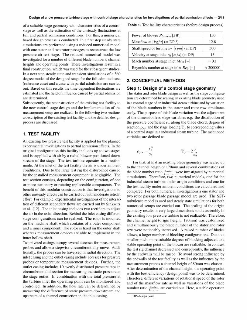
Table 1. Test facility characteristics (before design process)
Power of blower Pblower [kW] 150
Massflow Ûm [kg/s] (at DP 1) 12.8
Shaft speed of turbine nT [rpm] (at DP) 500
Velocity at stage inlet c0 [m/s] (at DP) 15
Mach number at stage inlet Ma0 [−] ≈ 0.1
Reynolds number at stage inlet Re0 [−] ≈ 200000
2. CONCEPTUAL METHODS
Step 1: Design of a control stage geometryThe stator and rotor blade design as well as the stage configura-
tion are determined by scaling an existing blade geometry used
in a control stage of an industrial steam turbine and by variation
of the blade numbers in the stator and rotor row simultane-
ously. The purpose of this blade variation was the adjustment
of the dimensionless stage variables e.g. the distribution of
the pressure coefficient cp along the blade chord, degree of
reaction ρy,s and the stage loading Ψy to corresponding values
of a control stage in a industrial steam turbine. The mentioned
variables are defined as:
ρy,s =y′′s
ys
Ψy = 2y
u22
For that, at first an existing blade geometry was scaled up
to the channel heigth of 170mm and several combinations of
the blade number ratiozrotorzst ator
were investigated by numerical
simulations. Therefore, two numerical models, one for the
industrial steam turbine under origin conditions and one for
the test facility under ambient conditions are calculated and
compared. For both numerical investigations a one stator and
two rotor passage blade passage model are used. The SST-
turbulence model is used and steady state simulations for both
numerical setups are carried out. The scaling of the origin
geometry results in very large dimensions so the assembly in
the existing low pressure turbine is not realizable. Therefore,
the channel height (origin height: 170mm) was customized
and simultaneously the blade number of the stator and rotor
row were noticeably increased. A raised number of blades
allows, a larger number of blocking configurations. Due to a
smaller pitch, more suitable degrees of blocking adjusted to a
stable operating point of the blower are realizible. In contrast
the test rig channel decreased and consequently, the influence
by the endwalls will be raised. To avoid strong influence by
the endwalls of the test facility as well as the influence by the
measurement probes a channel height of 80mm was chosen.
After determination of the channel height, the operating point
with the best efficiency (design point) was to be determined.
Therefore, different variations of rotational speed of the rotor
and of the massflow rate as well as variations of the blade
number ratiozrotorzst ator
are carried out. Here, a stable operation
1DP=design point

Design of a low pressure turbine stage with control stage characteristics for investigations of partial admission effects — 3/11
of the blower has to be ensured. Especially at partial admis-
sion conditions caused by additional losses a large shift in the
compressor map of the blower can be expected as shown in
the next section.
At the same time, the stage characteristics should be compa-
rable with corresponding values of above mentioned steam
turbine control stage at midspan.
In conclusion, it is necessary to achieve similar velocity trian-
gles in the relative frame for similar distribution of the pressure
coefficient cp,rel as well as the reaction of degree and the stage
loading. Additionally, the best efficiency will be achieved at
this conditions for a given rotational speed of the rotor. The
best efficiency point raises with increasing rotational speed
nT and massflow rate Ûm as long as the velocity triangles are
not changed. However, the pressure and enthalpy drop over
the stage increase simultaneously. At the limit of the blower
power a stable operation point can not be ensured.
The determination of the design point based on results of
steady state calculations at full admission conditions. The
rotational speed and the massflow were defined first and will
be changed if the resulting pressure drop over the stage is to
high considering the expected increasing of the pressure drop
caused by flow losses at partial admission conditions. So the
suitable operating point results from a iterative process.
Thus, the design point is defined at a massflow rate of
Ûm = 7kg/s and a shaft speed of nT = 500rpm with a blade
number combination of 44 stator and 75 rotor blades even
though better efficiency can be achieved at higher massflow.
The pressure coefficient is determined by referencing on ve-
locity in the relative frame. So the definition of cp,rel is:
cp,rel =p − p2
12ρw2
Due to this definition, the influence by the different rotational
speed in industrial steam turbines and in the presented LP
turbine will be unconsidered. At that operating point the degree
of reaction is ρy < 0.1 and the stage loading Ψh ≈ −2.92.
Figure 1 shows the corresponding distribution of the pressure
coefficient on the rotor blade at midspan for the investigated
cases. A good agreement between origin and RUB control
stage is recognizable except a small area at the suction side
near leading edge. Based on these studies, the configuration
with 44 stator and 75 rotor blades will be used for further
numerical investigations. In the following, the allowed degree
of blocking for the partial admission investigations has to be
estimated.
Figure 1. Pressure coefficient distribution for the origin and
scaled geometry RUB
Step 2: Determination of allowed blockage ratio
amountA large number of partial admission configurations are necce-
sary to determine influences by the degree of blocking on
magnitudes of the forces on the rotor blades. However, the
arc of the blockage is limited due to design and air supply
constraints. The different configurations of partial admission
are investigated and depicted in the compressor map of the
blower. Figure 2 shows the results at full and partial admission
condition respectively (40[deg] or ǫ = 88.89%). Based on
this studies a degree of blocking of 40 degrees is considered.
However, the blocking arc was increased up to 40.90[deg]
resulting in 5 blocked stator passages to ensure that the ends
of the blocking arc end at two edges of the stator blades.
Moreover, a sufficient large area near the blockage can be
investigated by traversing along the blockage till approximatly
≈ 33 degrees from the blokage borders. A large shift of the
pressure difference due to partial admission compared to full
admission is recognizable whereby increasing of the massflow
results in a increased shift. However, a stable operation under
partial admission condition is ensured.
Figure 2. Air blower map
Design of a low pressure turbine stage with control stage characteristics for investigations of partial admission effects — 4/11
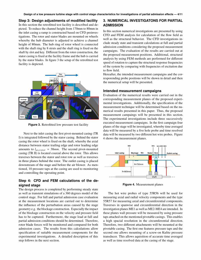
Step 3: Design adjustments of modified facilityIn this section the retrofitted test facility is described and de-
picted. To reduce the channel height from 170mm to 80mm in
the inlet casing a ramp is constructed based on CFD preinves-
tigations. The rotor and stator blades are mounted on wheels
whereby the hub diameter is adjusted to achieve a channel
height of 80mm. The hub ring of rotor wheel is connected
with the shaft ring by 8 struts and the shaft ring is fixed on the
shaft by slot and key. Different from the rotor construction, the
stator casing is fixed at the facility frame and the hub is carried
by the stator blades. In figure 3 the setup of the retrofitted test
facility is depicted.
Figure 3. Retrofitted low pressure test facility
Next to the inlet casing the first pivot-mounted casing (TR
I) is integrated followed by the stator casing. Behind the stator
casing the rotor wheel is fixed on the shaft, whereby the axial
distance between stator trailing edge and rotor leading edge
amounts to lax,rotor = 38mm. The second pivot-mounted
casing (TR II) is located coaxial above the rotor. This allows
traverses between the stator and rotor row as well as traverses
in three planes behind the rotor. The outlet casing is placed
downstream of the stage and before the air blower. As men-
tioned, 10 pressure taps at the casing are used to monitoring
and controlling the operating point.
Step 4: CFD and FEM calculations of the de-
signed stageThe design process is completed by performing steady state
as well as transient simulations of a 360 degrees model of the
control stage. For full and partial admission case evaluation
at the measurement locations are carried out to determine
the influence of the perturbation areas caused by the stage
geometry e.g. the blockage construction. Especially the impact
of the blockage construction on the velocity and pressure field
has to be captured. Furthermore, the stage load at full and
partial admission conditions should be determined. Therefore,
rotor blade forces will be monitored and compared for both
admission cases. The results from this calculations allow
specification of suitable measurement components for the
experimental investigations. A detailed description of this
step follows in the next section.
3. NUMERICAL INVESTIGATONS FOR PARTIAL
ADMISSION
In this section numerical investigations are presented by using
CFD and FEM analysis for calculation of the flow field as
well as the structural behavior. The CFD investigations in-
clude steady state and transient calculations at full and partial
admission conditions considering the proposed measurement
campaigns. The evaluation of the results are carried out at
the proposed measurement positions. Additional, structural
analysis by using FEM methods are performed for different
speed of rotation to capture the structural response frequencies
of the system by comparing with frequencies of excitation due
to flow field.
Hereafter, the intended measurement campaigns and the cor-
resporending probe positions will be shown in detail and then
the numerical setup will be presented.
Intended measurement campaignsEvaluation of the numerical results were carried out in the
corresponding measurement planes of the proposed experi-
mental investigations. Additionally, the specification of the
measurement technique will be determined based on the nu-
merical results presented in this paper. Thus, the proposed
measurement campaings will be presented in this section.
The experimental investigations include three successively
executed measurement campaigns. In the first campaign four
planes of the stage will be investigated, whereby time averaged
data will be measured by a five hole probe and time resolved
data will be measured by two different hot wire probes. Figure
4 shows the measurement planes.
Figure 4. Measurement planes
The hot wire probes of type 55R56 will be used for
measuring axial and radial velocity components and the type
55R57 for measuring axial and circumferential components.
Traverses in spanwise and circumferential direction in the
investigation planes ME1 as well as ME2-ME4 are intended. In
these planes wall pressure will be measured by using pressure
taps attached on the mentioned pivotable casings. This enables
a high spacial resolution in the circumferential direction.
Therefore, two different attachments will be mounted at the
pivotable casing. The first one features pressure taps and the
second one allows mounting of a screw-on Kulite pressure
transducer. This allows aquisition of accurate time averaged
as well as time resolved data at the casing of the stage.

Design of a low pressure turbine stage with control stage characteristics for investigations of partial admission effects — 5/11
In the second campaign pressure tabs at rotor midspan and
flush mounted Kulite transducers (Kulite LQ-125) are used
to measure the static pressure on the blade surface. Figure 5a
and 5b shows the rotor blade with pressure tabs and the rotor
blade with mounted Kulite transducers.
(a) Pressure tabs on pressure side of a rotor
blade
(b) Kulite transducers on pressure side of a
rotor blade
Figure 5. a) Rotor blade with 12 pressure tabs on pressure
side (15 tabs on suction side) b) Rotor blade with 5 Kulite
transducers on pressure side (7 Kulite transducers on suction
side)
The circumferetial position of the rotor can be determined
by a trigger signal, which is measured for each revolution. To
avoid the stochastic influences the sampling rate is defined by a
measurement study with different count of sampling data. The
data transfer from relative frame to the reference frame of the
rotor system is realized with a slip ring system and a compact
data logger system, implemented in the hollow shaft. For
the time averaged pressure measurements on the rotor blade,
the pressure taps are connected with a 64 channel pressure
trancducer ZOC 33/64 (Scanivalve) and subsequently the
analog data are transfered by the slip ring. Pressure fluctuation
on the Kulite transducers are recorded as analog signals by the
data logger system (Delphin ExpertVibro) and transformed to
digital signal by a A-D converter. The digital data are stored
on the internal hard drive and sended as one sampling for
each circumferential position to the computer. Measurement
of the velocity field by the Particle Image Velocimetry (PIV)
method completes the experimental investigations. A concept
for the PIV system is mounted on the pivot-mounted casings
and allows a traverse in circumferential direction and the
positioning of the system in the four different measurement
planes. These concept allows the measuring of the velocity at
the midspan area between the stator and rotor row, in the rotor
passage and downstream of the stage.
Numerical setup
CFD analysis
In this section the numerical setup for the CFD and subse-
quently the setup for the FEM analysis will be described.
Due to the partial admission configuration with a degree of
a blockage of 40.90 degree a periodic boundary condition in
circumferential direction is not possible, so the control stage
have to be modeled as a full annulus model. All numerical
investigations are carried out for the full admitted case (as
reference) as well as for the part admitted case.
The grids of stator and rotor passages as well as the inlet and
outlet domains are generated with the inhouse meshing tool
AxTurboMesh [8][1]. Overall a mesh with approximately 20
million elements is used whereby the blockage are assumed as
infinity thin with no slip wall conditions. In addition, all hub,
shroud and blade walls assumed as no slip walls. A detailed
grid independent study was conducted within a master thesis
by Mutlu [11]. The results of this study show a grid indepen-
dency at approximatly 20 million elements (figure 6).
Figure 6. Grid independeny study (Total pressure in plane
between stator and rotor)
The inlet domain with the stator row as well as the outlet
domain are stationary whereas the rotor domain is rotating
with a shaft speed of 500 rpm.
For the reference case, at inlet total pressure is set to pres-
sure of ambient whereas at outlet boundary a massflow of
m = 7kg/s is set first. Based on a steady state simulation the
corresponding static pressure at outlet was determined by av-
eraging. In the next step the averaged static pressure is defined
as the outlet boundary condition. The same total pressure at
inlet as well as the same static pressure at outlet were defined
for the partial admission case. Thus, the pressure drop at part
as well as at full loading is same. As a result, the blade forces
in the admitted arc of the partial admitted configuration and of
the full admitted configuration are equal. This allows a usefull
comparison of forces at partial admission and full admission
because all forces can be related to common reference value.

Design of a low pressure turbine stage with control stage characteristics for investigations of partial admission effects — 6/11
Air assumed under ideal gas conditions is used as working
medium and the total temperature is set to ambient temperature
of approximately 25C. The SST-tubulence model is used and
steady state and transient simulations are carried out. Steady
state simulations are performed with the so called frozen rotor
interface in order to connect rotating and non rotating parts.
For transient simulations a total number of 16 and 32 timesteps
per blade passing of the stator blade has been chosen for a
timestep study. The differences between the forces calculated
with the mentioned timesteps are negligible for the partial
admission and full admission case. Based on these results,
further increasing of the timestep count is not necessary.
Additional steady state simulations are carried out to deter-
mine the performance and efficiency of the test facility and to
estimate the losses at different operating points.
FEM analysis
In addition to the CFD analysis a modal analysis was carried
out to determine the eigenfrequencies of the rotor blades. The
eigenfrequencies are plotted in a Campbell diagram over the
rotational speed as well as the graphs of excitation frequencies
(figure 13). The excitation results from stator wakes caused by
trailing edges and from partial admission caused by interaction
of admitted and non admitted arcs. For the modal analysis
material data are used from data sheets to ensure the correct
behaviour of the rotor components. Figure 7 shows the
materials of the rotor components
Figure 7. Material of rotor components
4. RESULTS AND DISCUSSION
In this section CFD and FEM results are presented and dis-
cussed for the full and partial admission case. Initially, results
from steady state simulations will be described and evalu-
ated. Afterwards, results from the transient calculations will
be discussed, especially the time history of blade forces is
explained in detail. Finally, the blade passing frequency and
the frequency of disturbance caused by the partial admission
will be plotted in a frequency spectra and compared with
the eigenfrequencies of the rotor wheel. Further frequencies
occurring in the spectra are assessed in terms of importance
for the investigations, so that dominated frequencies can be
captured.
4.1 Results from steady state simulationsResults from steady state calculations are presented in cor-
responding planes of the proposed measurement campaigns.
The figures 8 and 9 show the pressure distribution in the plane
ME1-ME4 for full and partial admission.
Figure 8. Absolute pressure in plane ME1 at partial
admission
At the admitted arc of the stage in plane ME1 local
disturbance of pressure are merely caused by blade wakes from
the stator row, whereby ME2, ME3 and ME4 flow disturbance
is caused by wakes of the rotor blades. All mentioned wakes
generate losses and influence the efficency of the turbine
directly but are relatively low compared with losses caused by
part loading. Although in plane ME1 the field of influcence
by partial admission is limited mainly to the arc of blockage,
transporting of losses by the rotor in circumferential direction
are noticeably. Therefore, it can be considered that losses are
transported in circumferential direction in the ME2, ME3 and
ME4 planes. A remarkable disturbance due to the part loaded
stage occurs up to ME4. The rotation of the rotor and the
stagger angle of stator induce a momentum in circumferential
direction. These effects cause an increase of the mixing
intensity between the admitted and non admitted arc.
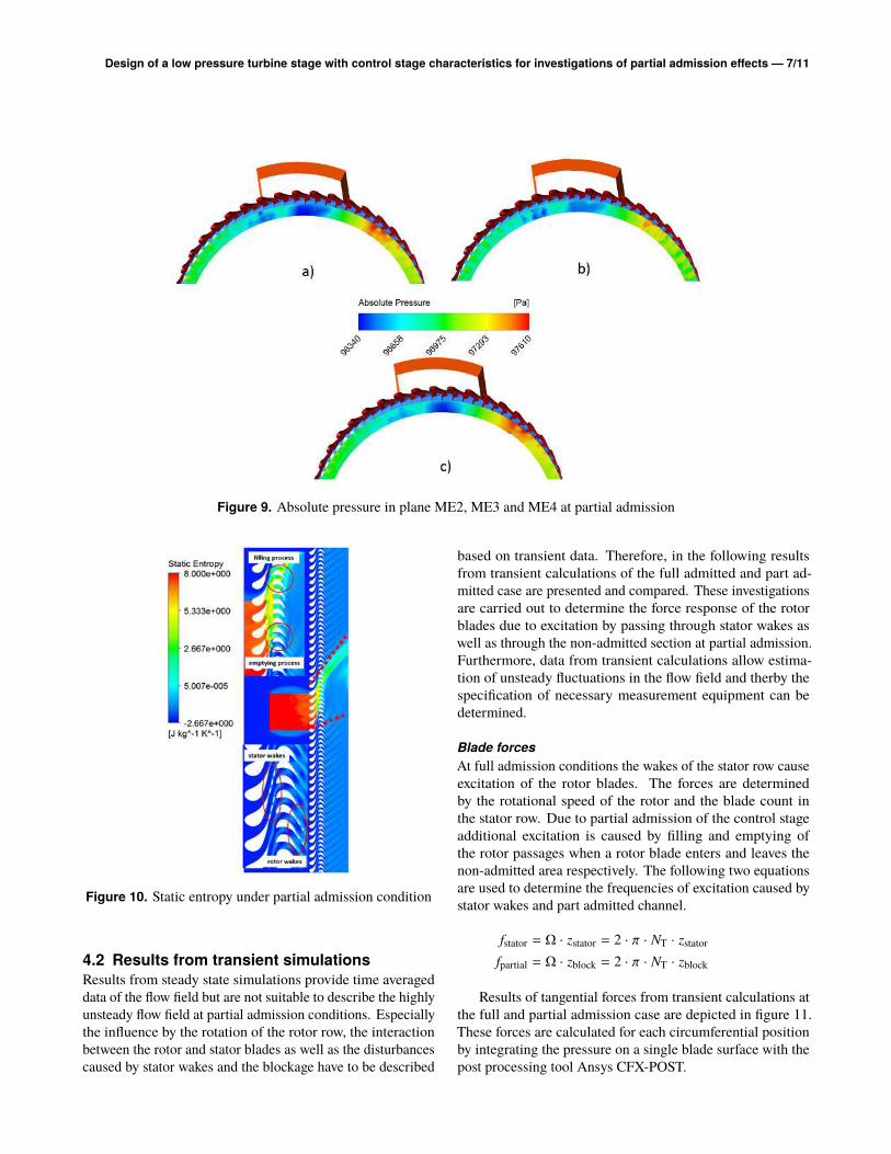
Figure 10 shows the distribution of static entropy at midspan.
Far downstream of the stage the field of influence by part
loading decreases noticable. The entropy production caused
by the stator wakes is distinctly less than the losses caused by
the specific effects results from the partial admission. It has to
be mentioned that the momentum in circumferential direction
causes the disturbance to propagate in direction of the rotation
even though, a sufficient range can be traversed by rotation of
the pivotable casings.
Design of a low pressure turbine stage with control stage characteristics for investigations of partial admission effects — 7/11
Figure 9. Absolute pressure in plane ME2, ME3 and ME4 at partial admission
Figure 10. Static entropy under partial admission condition
4.2 Results from transient simulations
Results from steady state simulations provide time averaged
data of the flow field but are not suitable to describe the highly
unsteady flow field at partial admission conditions. Especially
the influence by the rotation of the rotor row, the interaction
between the rotor and stator blades as well as the disturbances
caused by stator wakes and the blockage have to be described
based on transient data. Therefore, in the following results
from transient calculations of the full admitted and part ad-
mitted case are presented and compared. These investigations
are carried out to determine the force response of the rotor
blades due to excitation by passing through stator wakes as
well as through the non-admitted section at partial admission.
Furthermore, data from transient calculations allow estima-
tion of unsteady fluctuations in the flow field and therby the
specification of necessary measurement equipment can be
determined.
Blade forces
At full admission conditions the wakes of the stator row cause
excitation of the rotor blades. The forces are determined
by the rotational speed of the rotor and the blade count in
the stator row. Due to partial admission of the control stage
additional excitation is caused by filling and emptying of
the rotor passages when a rotor blade enters and leaves the
non-admitted area respectively. The following two equations
are used to determine the frequencies of excitation caused by
stator wakes and part admitted channel.
fstator = Ω · zstator = 2 · π · NT · zstator
fpartial = Ω · zblock = 2 · π · NT · zblock
Results of tangential forces from transient calculations at
the full and partial admission case are depicted in figure 11.
These forces are calculated for each circumferential position
by integrating the pressure on a single blade surface with the
post processing tool Ansys CFX-POST.

Design of a low pressure turbine stage with control stage characteristics for investigations of partial admission effects — 8/11
Figure 11. Tangential force at rotor blade for one revolution
As above mentioned, due to the same total (stage inlet)
to static (stage outlet) pressure ratio amplitudes of forces in
admitted arc of the partial admission case are comparable with
forces of the full admission case. However, amplitudes of
the forces which occur when rotor blades enter and leave the
admitted arc increase significantly. Furthermore, a change of
sign occurs by passing through the not admitted arc. When a
rotor blade leaves the admitted arc first of all, the suction side
of the blade enter the arc downstream of the blockage. On this
side the passage can not be supplied by the working medium,
so the static pressure decreases whereas the pressure side is
still admitted. As a result, a raised tangential force in rota-
tional direction can be observed whereby the amplitude is one
order of magnitude higher compared to the amplitude of force
caused by stator wakes. However, when the rotor leaves the
blocked arc the suction side will be admitted with the working
medium. Simultaneously, on the pressure side of the blade a
pressure drop can be observed caused by the emptying of the
rotor passage during passing of the blockage area. Due to the
change of sign the tangential force the single blade counteracts
the rotor wheel and acts as a compressor. Therefore, for each
revolution the rotor blades are loaded alternating towards and
opposite the rotational direction respectively. Figure 12 shows
the frequency spectra of the tangential force.
Although, the excitation frequency due to part loading is
considerably lower than the excitation caused by the stator
wakes the amplitudes are obviously larger and dominate the
frequency spectra. Additional frequencies caused by construc-
tional components do not occur, however linear combination
of the first both can affect on the frequency spectra. Further
excitation frequencies occur in the frequency spectra but the
two effects mentioned above dominate.
Figure 12. Frequency spectra of tangential force at rotor
blade
Structural analysis
Figure 13 shows the results from the structural analysis and
different engine orders caused by stator/rotor interaction as
well as caused by the blockage (EO2=two borders of the block-
age) and by 6 struts positioned in the inlet casing.
Figure 13. Campbell diagram of structural analysis of rotor
A noticeable shift between the first crossing point, where
resonance can be expected and the intended operating point is
recognizable, so that resonance problems in the system can be
excluded. The first critical mode occurs at the frequency of
approximatly 550Hz as the bending mode of the rotor struts.
Another operating points including resonance can be leave
out of consideration, because of a large shift to the design point.
Estimation of fluctuations:
Besides the safety aspect of the structural analysis, these in-
vestigation is necessary for consideration of forced response
effects.
The positions of the piezoresistive transducers on the rotor

Design of a low pressure turbine stage with control stage characteristics for investigations of partial admission effects — 9/11
blades are specified based on the transient results of the simula-
tions at full and partial admission. Therefore, local evaluation
points at different positions at midspan of the rotor blade are
defined in the numerical model. A total of 12 positions along
the blade profile are evaluated for one revolution of the rotor
blade. The figure 14 shows the corresponding results.
(a) Pressure side
(b) Suction side
Figure 14. Static pressure at rotor blade for one revolution
A noticeably difference of the pressure level on suction and
pressure side can be observed. Furthermore, the influence by
the stator wakes are distinctly less compared to the disturbance
due to the part admitted channel. Nevertheless, the amplitudes
are not negligible and are neccessary to determine all excita-
tions on the rotor blades. Two turning points in the graph of
the transient behaviour of pressure occur while passing the
blockage region, when the rotor entries and leaves the not
admitted area respectively. First, at beginning of the blockage
a minimum of the pressure is recognizable, whereas at the end
of the blockage a maximum appears. Immediately, as the rotor
blade enters the blockage, the emptying process of the rotor
passage causes a reduced pressure. The interruption of the air
supply downstream of the blockage causes the momentum of
the remaining medium to decrease until the end of the blockage.
When entering the admitted area, the high momentum flow
impinges the rotor passage and will decelareted due to the low
momentum flow in the passage. The stagnation of the fluid
causes an increasing of the static pressure raising up to the
maximum value. The emptying and filling process between
the entering and leaving of the blockage is observable for each
position of the rotor blade but with different intensity. Close
to the rotor trailing edges the amplitudes of the pressure signal
are one order of magnitude weaker than the amplitudes far
from the traling edge or near to the leading edge repectively.
The positions of the points DS 4 and 5 correspond to two
points near to the traling edge and show the lowest response
not only in the admitted but also in the not admitted area.
In figure 15 the frequency spectra of the pressure history is
depicted and shows the predominant frequencies for pressure
and suction side of the rotor blade.
Figure 15. Rotor frequency spectra at different positions (top:
pressure side=PS, bottom: suction side=SS
On pressure and suction side the low frequency excitation
due to the blockage causes the highest amplitudes, whereby the
magnitude of the amplitudes on the suction side are generally
higher. In addition, the high frequency disturbance caused
by the stator wakes are clearly recognizble at the frequency
of f = 366.66Hz as well as the multiple magnitude at f =
733.33Hz. Even higher frequencies are not noticeable, so the
maximum sampling rate of 50kHz per channel performed by
the A-D converter is sufficient for the proposed investigations.

Design of a low pressure turbine stage with control stage characteristics for investigations of partial admission effects — 10/11
5. CONCLUSION
In this paper the redesign of an existing low pressure test facility
to a single stage facility for investigations to partial admission
effects is described. In the first step, a suitable stage with
characterstics of a control stage at design point was designed
successful. The degree of reaction as well as the stage loading
are comparable to corresponding values of a control stage in
actual steam turbines. In doing so, the dominating effects of
partial admitted stages can be measured even though the flow
conditions in the test facility are not comparable to conditions
of a control stages in steam turbines. After determination
of a stage with characteristics of a control stage, numerical
investigation with CFD and FEM methods were carried out.
The CFD calculations have included steady state and transient
simulations under full and partial admission conditions. Based
on these results fields of influence and importance for the
later following experimental investigations are determined.
Furthermore, excitation sources caused by the unsteady flow
are determined and compared with eigenfrequencies of the
rotor wheel in a Campbell diagram. This indicates that
neither at the design point nor at other proposed operating
points the frequencies of excitation corresponds with any
eigenfrequency. Thus, an operating point under resonance
conditions can be excluded for all operating points which have
to been investigated.
In addition, to specify the characteristics of the measurement
technique fluctuations of the velocity and pressure field were
estimated. Therefore, the frequency spectra was evaluated for
different positions in the flow field and dominant frequencies
and amplitudes could be identified and at once the positions
where the measurment has to been placed. Based on the flow
conditions in the test facility highly sensitive measurement
is demand to resolve the fluctuations and to ensure small
measurement errors.
In addition to the successfull design process of the test facility,
the results shows the importance of the investigations of partial
admission effects in the design process of control stages once
more. The intended measurement at the retrofitted test facility
as well as the corresponding numerical investigations have to
give a wide indication of the unsteady flow in a part admitted
control stage. Redesign of the low pressure test facility to a
control stage enables extensive experimental investigations of
partial admission effects in the future. An incomparable spatial
as well as temporal resolution of a partly admitted control stage
will ensure high quality data for further numerical validation
and increase the comprehension of the phenomena, which
occur at partial admission.
NOMENCLATURE
Ûm [kg
s] Massflow
ǫ [−] Degree of admission
Ω [ 1s] Angular velocity
Ψ [−] Stage loading
ρ [kg
m3 ] Density
ρy [−] Degree of reaction
Θ [deg] Circumferential position
FΘ [N] Tangential Force
lax [m] Axial distance
c [ms
] Velocity
cp [−] Pressure coefficient
f [ 1s] Frequency
Ma [−] Mach number
n [ revs
] Rotational speed
p [Pa] Static pressure
P [W] Power of blower
Re [−] Reynolds number
w [ms] Velocity in relative frame
z [−] Blade number
REFERENCES
[1] Aulich, A.-L. ; Sauer, T. ; Iseni, S. ; Moreau, A. ;
Peitsch, D. ; Mailach, R. ; Micallef, D. ; Enghardt, L.
; Nicke, E. : Fan casing contouring under consideration of
aeroacoustics, mechanics, aeroelasticity and whole engine
performance. In: Deutscher Luft- und Raumfahrtkongress
2015, 2015
[2]Bohn, F. ; Funke, H.-H.-W. : Experimental Investigations
Into the Nonuniform Flow in a 4-Stage Turbine With
Special Focus on the Flow Equalization in the First Turbine
Stage. In: Proceedings of ASME Turbo Expo 2003 Volume
6 (Atlanta, Georgia, USA, June 16-19, 2003)
[3]Drexler, C. : Strömungsvorgänge und Verlustanteile in
ungleichförmig beaufschlagten Turbinenstufen, RWTH
Aachen, doctoral thesis, 1996
[4]Fridh, J. : Experimental Investigation of Performance,
Flow Interactions and Rotor Forcing in Axial Partial Ad-
mission Turbines, KTH, School of Industrial Engineering
and Management (ITM), Energy Technology, Heat and
Power Technology, doctoral thesis, 2012
[5]Gao, K.-K. ; Wang, S.-S. ; Shi, D.-B. : Unsteady
flow and load in 50% partial admission control stage
with different admitting arc distributions. In: Thermal
Science 20 (2016), Nr. suppl. 3, S. 805–813. http:
//dx.doi.org/10.2298/tsci160201203g. – DOI
10.2298/tsci160201203g

Design of a low pressure turbine stage with control stage characteristics for investigations of partial admission effects — 11/11
[6]He, L. : Computation of unsteady flow through steam
turbine blade rows at partial admission. In: Proceedings of
the Institution of Mechanical Engineers, Part A: Journal
of Power and Energy 211 (1997), Nr. 3, S. 197–205. http:
//dx.doi.org/10.1243/0957650971537105. – DOI
10.1243/0957650971537105
[7]Hushmandi, N. B.: Numerical Analysis of Partial Admis-
sion in Axial Turbines, KTH Stockholm, doctoral thesis,
2010
[8]Iseni, S. ; Micallef, D. ; Mailach, R. : Investigation
of Inlet Distortion on the Flutter Stability of a Highly
Loaded Transonic Fan Rotor. In: ASME Turbo Expo 2016:
Turbomachinery Technical Conference and Exposition
Volume 7B: Structures and Dynamics (Seoul, South Korea,
June 13–17, 2016), Nr. ASME Paper No. GT2016-56593
[9]Kalkkuhl, T. J.: Strömungssimulation einer teilbeauf-
schlagten Dampfturbine, Ruhr-Universität Bochum, doc-
toral thesis, 2014
[10]Lampart, P. ; Szymaniak, M. ; Kwidzinski, R. : Numer-
ical Investigation of Unsteady Flow in a Partial Admission
Control Stage of a 200MW turbine. In: Proc. 6thEuro-
pean Conference on Turbomachinery Fluid Dynamics and
Thermodynamics (Lille, France, March, 2005)
[11]Mutlu, E. : Numerische Untersuchung zur Teil-
beaufschlagung innerhalb einer Niedergeschwindigkeits-
forschungsturbine bei 30°, 40° und 60° Versperrung,
Ruhr-Universität Bochum, master thesis, 2016
[12]Sinkwitz, M. ; Engelmann, D. ; Mailach, R. : Ex-
perimental Investigation of Periodically Unsteady Wake
Impact on the Secondary Flow in a 1.5 Stage Full Annular
LPT Cascade with Modified T106 Blading. In: Proceed-
ings of ASME Turbo Expo 2017 (Charlotte, NC, USA,
June 26-30, 2017), Nr. ASME Paper No. GT2017-64390
[13]Tajc, L. ; Bednar, L. ; Polansky, J. ; Stastny, M.
: Radial Control Stage with Partial Steam Admission.
In: Proceedings of the 8 th International Symposium on
Experimental and Computational Aerothermodynamics
of Internal Flows (Lyon, France, July, 2007), Nr. Paper
No. ISAIF8-0014
[14]Tokuyama, Y. ; Funazaki, K. ichi ; Kato, H. ; Shimiya,
N. ; Shimagaki, M. ; Uchiumi, M. : Computational
Analysis of Unsteady Flow in a Partial Admission Super-
sonic Turbine Stage. In: ASME Turbo Expo 2014 Vol-
ume 2D: Turbomachinery (Düsseldorf, Germany, June,
2014), Nr. ASME Paper No.GT2014-26071. http:
//dx.doi.org/doi:10.1115/GT2014-26071. – DOI
doi: 10.1115/GT2014–26071
[15]Walzer, P. : Teilbeaufschlagung von Dampfturbinen-
regelstufen, RWTH Aachen, doctoral thesis, 1970