design of a growing robot inspired by plant grow th
TRANSCRIPT
Design of a Growing Robot Inspired by Plant Growth
The MIT Faculty has made this article openly available. Please share how this access benefits you. Your story matters.
Citation Yan, Tongxi et al. "Design of a Growing Robot Inspired by PlantGrowth." IEEE International Conference on Intelligent Robots andSystems, November 2019, Macau, China, Institute of Electrical andElectronics Engineers, January 2020. © 2019 IEEE
As Published http://dx.doi.org/10.1109/iros40897.2019.8968200
Publisher Institute of Electrical and Electronics Engineers (IEEE)
Version Author's final manuscript
Citable link https://hdl.handle.net/1721.1/127834
Terms of Use Creative Commons Attribution-Noncommercial-Share Alike
Detailed Terms http://creativecommons.org/licenses/by-nc-sa/4.0/
Design of a Growing Robot Inspired by Plant Growth*
Tongxi Yan1, Seiichi Teshigawara1, and H. Harry Asada, Member, IEEE1
Abstract— A novel design concept of expandable robotic arminspired by plant growth is presented. The robot can constructits own structure by converting a type of fluidized material intoa rigid structure at its growing point. The robot can extend itsstructure in multiple directions, and move through a windingspace to reach a point, which is otherwise difficult to access. Therobot with the rigid structure can also bear a significant load,has a plate to attach an end-effector, and can transport anobject. The robot satisfies three key functional requirementsthat are characteristic to plant growth. First, the robot iscapable of transporting structural materials to its growingpoint. Second, the robot is capable of transforming the materialinto a rigid structure. Third, it is capable of steering its growingpoint so that it is expanded in a desired direction. A proof-of-concept prototype is then presented that consists of a specialsprocket chain that can be switched between flexible/fluidizedand rigid states, a winch that can pull/transport the chain,and a steering system to direct the growing direction. Unlikeplants, this growing robot can retract its extended body, andcan extend in a different direction. The prototype demonstratesthat it meets all the functional requirements, and that it canmake sharp turns and move through obstacles.
Keywords: Industrial Robots, Mechanism Design
I. INTRODUCTION
In inspection, maintenance, and assembly of complexmachines and systems, robots often have to reach objectsthrough a narrow, winding space. In logistics automation,robots also need to pick up goods at the back of a shelf ina warehouse. This type of tasks, which is referred to as theLast One-Foot Problem, is posing a challenge to robot designand control [1]. Traditional robots consisting of a series ofservoed joints or a parallel linkage structure are unable toreach such destinations.
In the robotics community, a number of innovative robotshaving unique body shapes and characteristics have beeninvestigated. These include soft robots, mobile robots, andmotion planning techniques utilizing shrinking and growinggeometries that can be applied to the last one-foot problem[1]–[6]. Of particular interest is the soft mobile robot by thegroup at Stanford University [2]. It resembles a plant that canextend its body through a narrow channel. Unfortunately,however, these robots are often unable to bear a largeload. Soft robots, in particular, cannot position their end-effectors precisely at a desired point in space. They do noteven possess an appropriate base to mount an end-effector.Furthermore, mobile robots in general are difficult to use ina practical setting, since they are unable, or find it difficult,
*This work was supported by NSK Ltd.1The authors are with the d’Arbeloff Laboratory for Information Sys-
tems and Technology in the Department of Mechanical Engineering, Mas-sachusetts Institute of Technology, Cambridge, MA 02139, USA. Email:{tyan, seiichi, asada}@mit.edu
to reach the entrance of such a cluttered area. Our view isthat some type of end-effector or a small robot attached tothe tip of a robot will be a feasible, cost-effective solution.
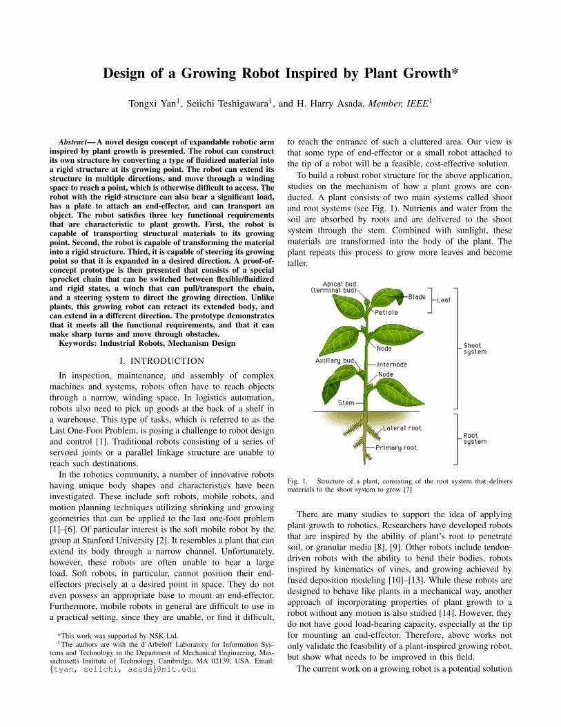
To build a robust robot structure for the above application,studies on the mechanism of how a plant grows are con-ducted. A plant consists of two main systems called shootand root systems (see Fig. 1). Nutrients and water from thesoil are absorbed by roots and are delivered to the shootsystem through the stem. Combined with sunlight, thesematerials are transformed into the body of the plant. Theplant repeats this process to grow more leaves and becometaller.
Fig. 1. Structure of a plant, consisting of the root system that deliversmaterials to the shoot system to grow [7]
There are many studies to support the idea of applyingplant growth to robotics. Researchers have developed robotsthat are inspired by the ability of plant’s root to penetratesoil, or granular media [8], [9]. Other robots include tendon-driven robots with the ability to bend their bodies, robotsinspired by kinematics of vines, and growing achieved byfused deposition modeling [10]–[13]. While these robots aredesigned to behave like plants in a mechanical way, anotherapproach of incorporating properties of plant growth to arobot without any motion is also studied [14]. However, theydo not have good load-bearing capacity, especially at the tipfor mounting an end-effector. Therefore, above works notonly validate the feasibility of a plant-inspired growing robot,but show what needs to be improved in this field.
The current work on a growing robot is a potential solution
to the class of the last one-foot problem. It is fully functionalon its own, extending from a base and navigate throughthe environment that human have little to no access to. Itcan be also mounted on an industrial robot and extends itsendpoint into a cluttered space. In either case, the robot canbe fully autonomous with proper motion planning algorithmsor manually operated, but this is beyond the scope of thispaper. However, the basic design concept to be detailedbelow can go beyond the original mission of the project.The plant-inspired growing robot can construct an arbitraryrigid structure by converting a flexible structural materialinto a rigid structure. Traditionally, structure is mostly pre-determined by design and its configuration is changed bymeans of active control of servoed joints. In contrast, thenew plant-inspired growing robot does not possess fixed linklengths and a fixed kinematic structure. Rather, the structureis determined and constructed in real time. Similar to rootsand trunks of a plant, the actual shape is determined throughinteractions with the environment, which are unpredictable.
The following sections will describe the fundamentalfunctionality of the growing point of a plant, followed bya specific mechanical design concept as an embodiment ofthe growing point functionality. Then, a preliminary proof-of-concept prototype will be designed, fabricated, and tested.
II. FUNDAMENTAL FUNCTIONAL REQUIREMENTS
The design needs to be started by turning the functionsof a plant to engineering functional requirements. First, asstated above, materials are delivered from the root to theplant body. Once materials are delivered, the plant growslarger. This means that the robot needs to expand from thebase, which is equivalent to soil for the plant. Second, theplant constructs its body from the materials. On the robotside, the body must stay rigid after expanding from the base.Third, as the plant grows, it can adapt to different geometriesfor various reasons. It can grow to avoid obstacles or to gainmore sunlight. This needs to be the same for a robot. It needsto be able to steer to different directions in order to avoidobstacles. To summarize, three functional requirements arestated and listed below:
1) Transport materials from a base to a growing pointa) This entails that the material is flexible, so that it
can conform to an arbitrary shape of the structurethat has been constructed and is amenable fortransportation.
b) This also entails a mechanism for pushing,pulling, sucking, pumping, etc. of the materialfrom a base station to the growing point.
2) Convert or transform the material to a rigid structurea) This entails a mechanism that dispense the mate-
rials continually or unit by unit at the tip of thegrowing point.
b) This also entails a type of locking mechanism,so that the dispensed materials or unit can beimmobilized.
c) Furthermore, this entails that the dispensingmechanism can push its own body forward, leav-ing the dispensed materials or unit behind.
3) Steer the growing directiona) The growing point mechanism must have the
means to rotate its body, so that each unit ormaterial can be dispensed in a desired direction.
b) Torque must be generated between the segmentsof the dispensed materials or units that have beenimmobilized and the head of the growing pointmechanism.
These are fundamental functional requirements for plantsas well as for growing robots. Note that the above functionalrequirements are nothing specific to a particular embodiment.It can be realized with a biological means, or an abiologicalmeans. Here we pursue an abiological means, that is, anengineered entity, or a robot. The true value of the above ar-gument of fundamental functional requirements is to releaseus from considering only existing mechanisms and existingbiological systems. There may be other ways of realizing thesame functionality using different means.
III. PROTOTYPE DESIGN AND FABRICATION
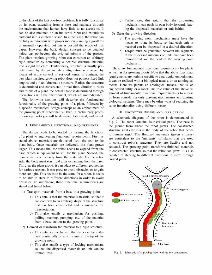
A schematic diagram of the robot is demonstrated inFig. 2. The robot contains four critical parts. The base isthe ground from where the robot grows. The constructedstructure (red ellipses) is the body of the robot that needsto remain rigid. The fluidized materials (green ellipses)are equivalent to the ’nutrients’ of plants that are usedto construct robot’s structure. They are flexible and notactuated. The growing point transforms fluidized materialsto constructed structure so that the robot can grow. It is alsocapable of steering to different directions to move throughcurved paths.
Fig. 2. Schematic of a growing robot with its key components.
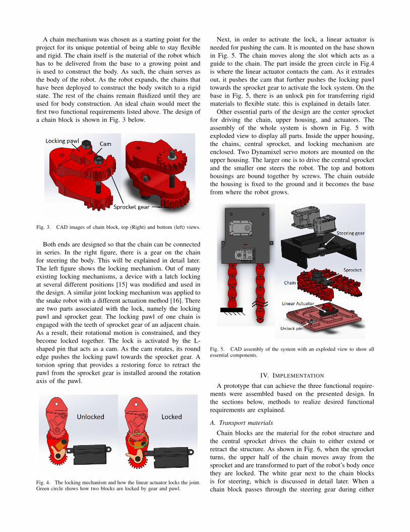
A chain mechanism was chosen as a starting point for theproject for its unique potential of being able to stay flexibleand rigid. The chain itself is the material of the robot whichhas to be delivered from the base to a growing point andis used to construct the body. As such, the chain serves asthe body of the robot. As the robot expands, the chains thathave been deployed to construct the body switch to a rigidstate. The rest of the chains remain fluidized until they areused for body construction. An ideal chain would meet thefirst two functional requirements listed above. The design ofa chain block is shown in Fig. 3 below.
Fig. 3. CAD images of chain block, top (Right) and bottom (left) views.
Both ends are designed so that the chain can be connectedin series. In the right figure, there is a gear on the chainfor steering the body. This will be explained in detail later.The left figure shows the locking mechanism. Out of manyexisting locking mechanisms, a device with a latch lockingat several different positions [15] was modified and used inthe design. A similar joint locking mechanism was applied tothe snake robot with a different actuation method [16]. Thereare two parts associated with the lock, namely the lockingpawl and sprocket gear. The locking pawl of one chain isengaged with the teeth of sprocket gear of an adjacent chain.As a result, their rotational motion is constrained, and theybecome locked together. The lock is activated by the L-shaped pin that acts as a cam. As the cam rotates, its roundedge pushes the locking pawl towards the sprocket gear. Atorsion spring that provides a restoring force to retract thepawl from the sprocket gear is installed around the rotationaxis of the pawl.
Fig. 4. The locking mechanism and how the linear actuator locks the joint.Green circle shows how two blocks are locked by gear and pawl.
Next, in order to activate the lock, a linear actuator isneeded for pushing the cam. It is mounted on the base shownin Fig. 5. The chain moves along the slot which acts as aguide to the chain. The part inside the green circle in Fig.4is where the linear actuator contacts the cam. As it extrudesout, it pushes the cam that further pushes the locking pawltowards the sprocket gear to activate the lock system. On thebase in Fig. 5, there is an unlock pin for transferring rigidmaterials to flexible state. this is explained in details later.
Other essential parts of the design are the center sprocketfor driving the chain, upper housing, and actuators. Theassembly of the whole system is shown in Fig. 5 withexploded view to display all parts. Inside the upper housing,the chains, central sprocket, and locking mechanism areenclosed. Two Dynamixel servo motors are mounted on theupper housing. The larger one is to drive the central sprocketand the smaller one steers the robot. The top and bottomhousings are bound together by screws. The chain outsidethe housing is fixed to the ground and it becomes the basefrom where the robot grows.
Fig. 5. CAD assembly of the system with an exploded view to show allessential components.
IV. IMPLEMENTATION
A prototype that can achieve the three functional require-ments were assembled based on the presented design. Inthe sections below, methods to realize desired functionalrequirements are explained.
A. Transport materials
Chain blocks are the material for the robot structure andthe central sprocket drives the chain to either extend orretract the structure. As shown in Fig. 6, when the sprocketturns, the upper half of the chain moves away from thesprocket and are transformed to part of the robot’s body oncethey are locked. The white gear next to the chain blocksis for steering, which is discussed in detail later. When achain block passes through the steering gear during either

Fig. 6. The middle sprocket rotates (yellow arrow) to feed blocks out(dark orange arrow) from one side and pulls flexible chain from anotherside (light orange arrow).
extension or retraction, the gear on the chain block mesheswith the steering gear. To ensure that gears don’t jam duringthe movement, the steering gear needs to rotate at a speedand direction matching with the speed and direction of thechain’s movement. Ideally, the chain is constrained so that itundergoes linear motion when passing through the steeringgear, and the relation between the rotational speed of steeringgear and the speed of the chain is described as below:
ωgear =2vchainPDgear
(1)
where ωgear is the rotational speed of the steering gear,vchain is the linear velocity of the chain, and PDgear isthe pitch diameter of the steering gear. This equation tellshow fast the steering gear needs to spin with respect to themoving speed of the chain.
B. Convert materials to rigid structure
Fig. 7. Method of engaging the lock with CAD image to show where thelinear actuator is mounted to the base.
Materials delivered to the growing point of the robotare flexible because they need to fit onto the sprocket. Toconstruct the robot structure, these materials need to betransformed into rigid parts. The lock mechanism on eachchain block can constrain the rotation, forming the neededstructures. Fig. 7 explains the method of engaging the lockin the system. The linear actuator pushes the cam from thelocation indicated by the green arrow to lock a block. Oncethe orientation is determined, its tip is elongated to reach andpush the cam.
To unlock the chain, a white pin in Fig. 8 is installed ontothe housing base. While unlocking the chain, it also needsto not interfere with locked blocks for constructing the robotbody. To achieve this, the pin can rotate in one direction, butnot the other, shown by green arrows. When locked blocksare pushed outside the housing, the pin rotates to make spacefor blocks to pass through and afterwards, it retracts to theoriginal position by a torsion spring embedded on the inside.During the process of retracting the chain, it releases the lockby pushing the cam out of singular position.
Fig. 8. Unlocking mechanism with blue arrows indicating the direction ofchain’s motion. (a) As the locked chain passes through unlock pin, the pinrotates clockwise to conform to the motion of chain. (b) When retractingthe robot, the pin pushes the cam to release the lock.
C. Steer the growing direction
Fig. 9. Steering mechanism. Locked portion of the chain is grounded tothe hand. As the white steering gear rotates (white arrow), the whole headtilts to a different direction.
Steering the robot to grow towards the desired directionis the last functional requirement of the design. As brieflymentioned earlier, the steering is achieved by rotating thehousing and other components of the robot with respectto the locked structure. The steering gear grounded to thehousing meshes with the gear on the locked portion of thechain. As it is driven by a Dynamixel servo motor, it rollsaround the gear on a fixed chain. As a result, the wholehousing is steered to different directions. Details can be seenin Fig. 9.
V. EXPERIMENT
The sequence of operations of this robot is to first feed thechain. Next, the steering gear determines the orientation that

the robot wants to move to. The chain needs to be lockedso that it remains at that orientation, so the linear actuatoris driven to lock the chain. Afterwards, the sprocket pusheslocked chain outside the housing and builds the body. Thesame sequence is repeated to expand the robot.
Retracting the robot follows the inverse of the expansionsequence. In order to pull back the chain, the lock needs tobe released. Additionally, the chain needs to be repositionedto a straight configuration and this process requires that thechain is unlocked. Therefore, the lock is released first, andthen the steering gear rotates to complete the alignment. Thisis one cycle and is repeated until all body parts are retracted.
Fig. 10. Demonstration of operating the robot. It first expands straight andthen makes a sharp left turn, going around the yellow obstacle.
Fig. 11. Demonstration of going through obstacles. The robot is manuallyoperated to go through yellow obstacles and then retract to its originalposition.
A simple motion of the robot is demonstrated in Fig. 10.The robot first moves straight for several chain blocks. Then,in order to go around the yellow obstacle, the robot makes aleft turn. Each chain block can steer up to 60 degrees. Themotion demonstrates that the robot can make sharp turns.
Fig. 11 is another demonstration of the robot movingthrough obstacles. In order to move through the spacebetween two obstacles, the robot needs to first align itselfwith the space. It makes a right turn and then makes aleft turn. After aligning with the space, it moves straightto reach the destination. To show that the robot is capable ofretracting to the original position, it pulls its head back to thebase by deconstructing the body. Chain blocks are unlockedand retracted one by one during this process and the robot’sgrowing point eventually goes back to the starting position.
VI. DESIGN ITERATIONS
To reduce backlash and increase locking strength of thecurrent design, the second version of the chain with anew locking mechanism was created. The chain block isassembled from two nearly identical parts, one forming theupper half and the other forming the lower half of a chainblock. A bushing is placed between the interface of two chainblocks to reduce friction.
Fig. 12. Second design of chain block and locking mechanism withexploded view. The yellow disk is the mounting plate for pawls and isfixed to the yellow chain block. Note that fasteners are not included andcomponents for the lock are assembled only on top surface. In practice,same components are assembled on bottom surface as well.
Fig. 13. Locking mechanism of the actual part with CAD images to showthe orientation of the cam at each state.
The new locking mechanism consists of two pawls withmultiple teeth fixed to a chain block that mesh with an innergear on the other chain block to engage the lock. Meshingthese parts constrains the rotation of two chain blocks about
each other. The pawls are pushed against the inner gearby a cam sitting between them. Rotating the cam by 90degrees in either direction can switch between the lockedand unlocked states. To separate the pawls from inner gear,a tension spring is attached to the end of two pawls. Whenthe cam no longer pushes the pawls against the inner gear,the springs pulls the pawls to disengage with the inner gear.The cover placed on top of the lock (shown as transparentin the assembled view of Fig. 12) blocks any particles largeenough to hinder the locking motion. This lock is on boththe top and bottom sides of the chain so that the symmetryreduces twist due to torsion. Having two pairs of lock alsoenhances the locking strength. A prototype of this design wasfabricated and Fig. 13 shows both the locked and unlockedstates of the fabricated prototype.
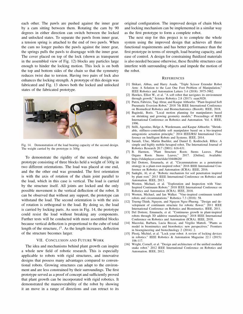
Fig. 14. Demonstration of the load bearing capacity of the second design.The weight carried by the prototype is 500g
To demonstrate the rigidity of the second design, theprototype consisting of three blocks held a weight of 500g intwo different orientations. The load was placed at one end,and the the other end was grounded. The first orientationis with the axis of rotation of the chain joint parallel tothe load, which in this case is vertical. The load is carriedby the structure itself. All joints are locked and the onlypossible movement is the vertical deflection of the robot. Itcan be observed that without any support, the prototype canwithstand the load. The second orientation is with the axisof rotation is orthogonal to the load. By doing so, the loadis carried by locking parts. As seen in Fig. 14, the prototypecould resist the load without breaking any components.Further tests will be conducted with more assembled blocksbecause vertical deflection is proportional to the cube of totallength of the structure, l3. As the length increases, deflectionof the structure becomes larger.
VII. CONCLUSION AND FUTURE WORK
The idea and mechanisms behind plant growth can inspirea whole new field of robotic research. This is especiallyapplicable to robots with rigid structures, and innovativedesigns that possess many advantages compared to conven-tional robots. Growing structures can adapt to the environ-ment and are less constrained by their surroundings. The firstprototype served as a proof of concept and sufficiently provedthat plant growth can be incorporated with rigid robotics. Itdemonstrated the maneuverability of the robot by showingit an move in a range of directions and can retract to its
original configuration. The improved design of chain blockand locking mechanism can be implemented in a similar wayas the first prototype to form a complete robot.
The next step for this project is to complete the wholesystem using the improved design that achieves all threefunctional requirements and has better performance than thefirst prototype in terms of strength, load bearing capacity, andease of control. A design for constraining fluidized materialsis also needed because otherwise, these flexible structures caninterfere with surrounding objects and impede the motion ofthe robot.
REFERENCES
[1] Shikari, Abbas, and Harry Asada. ”Triple Scissor Extender RobotArm: A Solution to the Last One Foot Problem of Manipulation,”IEEE Robotics and Automation Letters 3.4 (2018): 3975-3982.
[2] Hawkes, Elliot W., et al. ”A soft robot that navigates its environmentthrough growth,” Science Robotics 2.8 (2017): eaan3028.
[3] Putzu, Fabrizio, Taqi Abrar, and Kaspar Althoefer. ”Plant-Inspired SoftPneumatic Eversion Robot,” 2018 7th IEEE International Conferenceon Biomedical Robotics and Biomechatronics (Biorob). IEEE, 2018.
[4] Baginski, Boris. ”Local motion planning for manipulators basedon shrinking and growing geometry models,” Proceedings of IEEEInternational Conference on Robotics and Automation. Vol. 4. IEEE,1996.
[5] Stilli, Agostino, Helge A. Wurdemann, and Kaspar Althoefer. ”Shrink-able, stiffness-controllable soft manipulator based on a bio-inspiredantagonistic actuation principle,” 2014 IEEE/RSJ International Con-ference on Intelligent Robots and Systems. IEEE, 2014.
[6] Saranli, Uluc, Martin Buehler, and Daniel E. Koditschek. RHex: Asimple and highly mobile hexapod robot, The International Journal ofRobotics Research 20.7 (2001): 616-631.
[7] B. Harmon, ”Plant Structure Roots Stems Leaves. PlantOrgans Roots Stems Leaves,” 2017. [Online]. Available:https://slideplayer.com/slide/10448620/
[8] Del Dottore, Emanuela, et al. ”Circumnutations as a penetrationstrategy in a plant-root-inspired robot.” 2016 IEEE International Con-ference on Robotics and Automation (ICRA). IEEE, 2016.
[9] Sadeghi, Al, et al. ”Robotic mechanism for soil penetration inspiredby plant root.” 2013 IEEE International Conference on Robotics andAutomation. IEEE, 2013.
[10] Wooten, Michael, et al. ”Exploration and Inspection with Vine-Inspired Continuum Robots.” 2018 IEEE International Conference onRobotics and Automation (ICRA). IEEE, 2018.
[11] Wooten, Michael, and Ian Walker. ”Vine-inspired continuum tendrilrobots and circumnutations.” Robotics 7.3 (2018): 58.
[12] Truong-Thinh, Nguyen, and Nguyen Ngoc-Phuong. ”Design and de-velopment of continuum structure for robotic flower.” 2011 IEEEInternational Conference on Robotics and Biomimetics. IEEE, 2011.
[13] Del Dottore, Emanuela, et al. ”Continuous growth in plant-inspiredrobots through 3D additive manufacturing.” 2018 IEEE InternationalConference on Robotics and Automation (ICRA). IEEE, 2018.
[14] Mazzolai, Barbara, Lucia Beccai, and Virgilio Mattoli. ”Plants asmodel in biomimetics and biorobotics: new perspectives.” Frontiersin bioengineering and biotechnology 2 (2014): 2.
[15] Plooij, Michiel, et al. ”Lock your robot: A review of locking devicesin robotics.” IEEE Robotics & Automation Magazine 22.1 (2015):106-117.
[16] Wright, Cornell, et al. ”Design and architecture of the unified modularsnake robot.” 2012 IEEE International Conference on Robotics andAutomation. IEEE, 2012.