design of a composite carabiner for rock climbing - faİrex of a composite carabiner for rock... ·...
TRANSCRIPT
Final year project, MEng, Mechanical Engineering, Imperial College London
Supervisor: Dr Bamber Blackman
5 June 2008
Design of a composite carabiner for rock climbing
Final Report
Virgil Scott
Abstract
In rock climbing and mountaineering there is a strong focus on reducing the weight of all
equipment. By reducing the weight of equipment a climber will expend less energy
working against gravity and thus be able to climb further and faster. This project explores
the feasibility of creating a lightweight carabiner using composite materials. A set of
detailed requirements for a carabiner have been defined based on international safety
standards, geometrical criteria and environmental resistance criteria. Material and
manufacturing options have been studied and related to the carabiner application.
Toughness, damage tolerance, damage detection and wear were determined to be
problematic aspects of composite materials for lightweight carabiner design. Literature
research was used to find methods of improving composite toughness. Two design options
were proposed and one of these designs was described in detail. The proposed design
makes use of injection moulded, short carbon fibre/PEEK composite, specifically, Victrex
90HMF40. A CAD model and a rapid prototyped model of the proposed design were
created. A carabiner made from composite materials is likely to be up to 40% lighter than a
conventional aluminium carabiner. Producing composite carabiners is likely to be more
expensive than aluminium carabiner production – particularly if hand lay-up is used.
Limited testing and finite element analysis were carried out as part of the early stages of
design optimisation. Further analysis and development is required before carabiner
production can begin.

2
Contents
1 Introduction … … … … … 3
2 Background … … … … … 4
2.1 General 4
2.2 Existing products 8
2.3 Manufacture 9
3 Design criteria … … … … 10
3.1 Requirements 11
3.2 Design guidelines 11
3.3 Additional Testing 12
4 Materials … … … … … 13
4.1 Fibres 14
4.2 Matrix 16
4.3 Material selection 17
5 Manufacturing processes … … … 21
5.1 Open mould processes 22
5.2 Closed mould processes 24
6 Literature Research … … … … 27
6.1 Toughening methods 28
6.2 Matrix 30
6.3 Fibre 30
6.4 Processing 31
7 Design … … … … … … 32
7.1 Initial exploration 32
7.2 Brainstorming 34
7.3 Proposed designs 36
7.3.1 Prepreg/racket 37
7.3.1 Injection moulded 38
7.4 3D modelling and rapid prototyping 39
7.5 Costing 42
8 FEA and testing … … … … 43
9 Future work … … … … … 45
10 Conclusions … … … … … 45
11 Acknowledgments … … … … 46
12 References … … … … … 46
3
1 Introduction
In rock climbing and mountaineering there is a strong focus on reducing the weight of all
equipment. By reducing the weight of equipment a climber will expend less energy
working against gravity and will thus be able to climb further and faster. In modern alpine
climbing this has been taken to extremes, with climbers carrying minimal food and water,
inadequate sleeping equipment and a reduced amount of fall protection equipment [1].
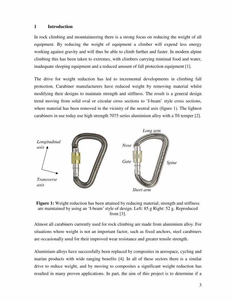
The drive for weight reduction has led to incremental developments in climbing fall
protection. Carabiner manufacturers have reduced weight by removing material whilst
modifying their designs to maintain strength and stiffness. The result is a general design
trend moving from solid oval or circular cross sections to ‘I-beam’ style cross sections,
where material has been removed in the vicinity of the neutral axis (figure 1). The lightest
carabiners in use today use high strength 7075 series aluminium alloy with a T6 temper [2].
Figure 1: Weight reduction has been attained by reducing material; strength and stiffness
are maintained by using an ‘I-beam’ style of design. Left: 85 g Right: 52 g. Reproduced
from [3].
Almost all carabiners currently used for rock climbing are made from aluminium alloy. For
situations where weight is not an important factor, such as fixed anchors, steel carabiners
are occasionally used for their improved wear resistance and greater tensile strength.
Aluminium alloys have successfully been replaced by composites in aerospace, cycling and
marine products with wide ranging benefits [4]. In all of these sectors there is a similar
drive to reduce weight, and by moving to composites a significant weight reduction has
resulted in many proven applications. In part, the aim of this project is to determine if a
Long arm
Spine
Short arm
Gate
Longitudinal
axis
Transverse
axis
Nose
4
carabiner made from composite materials is likely to be significantly lighter than current
aluminium alloy carabiners – without sacrificing safety. In addition, the performance of
available materials and manufacturing processes will be investigated to determine the
feasibility of creating a composite carabiner. Finally, a number of design options will be
suggested and one will be examined in more detail. First, the context of the project will be
discussed in terms of what carabiners are currently available and how they are used – this
will help establish a detailed set of requirements.
2 Background
2.1 General
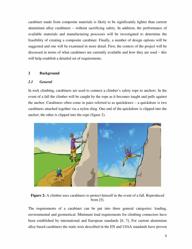
In rock climbing, carabiners are used to connect a climber’s safety rope to anchors. In the
event of a fall the climber will be caught by the rope as it becomes taught and pulls against
the anchor. Carabiners often come in pairs referred to as quickdraws – a quickdraw is two
carabiners attached together via a nylon sling. One end of the quickdraw is clipped into the
anchor; the other is clipped into the rope (figure 2).
Figure 2: A climber uses carabiners to protect himself in the event of a fall. Reproduced
from [5].
The requirements of a carabiner can be put into three general categories: loading,
environmental and geometrical. Minimum load requirements for climbing connectors have
been established by international and European standards [6, 7]. For current aluminium
alloy based carabiners the static tests described in the EN and UIAA standards have proven

5
to be sufficient to judge their safety. However, composites have low impact strength
relative to aluminium alloys and composite failure mechanisms can be highly rate
dependant [8, 9]. In this case, a static test is likely to be insufficient to determine the ability
of a composite carabiner to withstand the sudden impact of a climbing fall. A more
appropriate test might involve reproducing a ‘worst case scenario’ fall under controlled
conditions. This kind of test will approximate the force history and the force distributions
(of the rope-carabiner and carabiner-anchor interfaces) of a real fall.
During normal use a carabiner is likely to be dropped onto hard surfaces, aluminium alloy
carabiners often sustain minor surface indentations and scratches from these impacts and
continue to hold falls without failure. The drop height could vary from less than 1 m to
hundreds of metres, although a carabiner is unlikely to be reused after a drop of that
distance. A composite carabiner might incur defects or delamination from these kinds of
impacts. This internal damage would not necessarily be visible [10] to the naked eye and
other forms of non-destructive testing (NDT), such as ultrasound, would be required.
Figure 3: UIAA standards for the minimum strength of a carabiner, the relevant rows for a
standard carabiner are highlighted [7].
Environmental considerations are important because moisture adsorption and temperature
variation can have significant effects on the strength of composites [8]. Carabiners can be
exposed to harsh temperature ranges; from -40°C at the summit of Everest to +80°C or

6
higher due to frictional heating whilst abseiling. In addition, it is pertinent to know the
effects of a change in environmental pH, UV light and general chemical resistance
properties of the carabiner material.
There are geometrical and other design requirements on a carabiner due to the existing
framework of interactions between items of rock climbing protective equipment. Some of
these are set out in the EU and UIAA standards (figure 4).
Figure 4: An extract of the design requirements set out in UIAA standards [7].
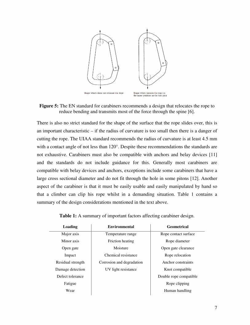
The EN standard [6] defines in more detail the required clearances and other geometrical
properties that enable carabiners to function correctly when used with climbing ropes;
some aspects are not defined strictly and instead come as recommendations. For example it
is recommended that carabiners are designed such that when loaded, most of the force is
taken by the spine (figure 5). Carabiners are inevitably weaker on the gated side due to
stress concentrations where the gate connects to the body; biasing the load towards the
spine reduces the stress on the weaker side. In addition it means that there is less bending –
that is, the spine is essentially held in pure tension, thus failure occurs close to its pure
tensile strength (this discussed further in the FEA and testing section later).
7
Figure 5: The EN standard for carabiners recommends a design that relocates the rope to
reduce bending and transmits most of the force through the spine [6].
There is also no strict standard for the shape of the surface that the rope slides over, this is
an important characteristic – if the radius of curvature is too small then there is a danger of
cutting the rope. The UIAA standard recommends the radius of curvature is at least 4.5 mm
with a contact angle of not less than 120°. Despite these recommendations the standards are
not exhaustive. Carabiners must also be compatible with anchors and belay devices [11]
and the standards do not include guidance for this. Generally most carabiners are
compatible with belay devices and anchors, exceptions include some carabiners that have a
large cross sectional diameter and do not fit through the hole in some pitons [12]. Another
aspect of the carabiner is that it must be easily usable and easily manipulated by hand so
that a climber can clip his rope whilst in a demanding situation. Table 1 contains a
summary of the design considerations mentioned in the text above.
Table 1: A summary of important factors affecting carabiner design.
Loading Environmental Geometrical
Major axis
Minor axis
Open gate
Impact
Residual strength
Damage detection
Defect tolerance
Fatigue
Wear
Temperature range
Friction heating
Moisture
Chemical resistance
Corrosion and degradation
UV light resistance
Rope contact surface
Rope diameter
Open gate clearance
Rope relocation
Anchor constraints
Knot compatible
Double rope compatible
Rope clipping
Human handling

8
2.2 Existing products
It is important to consider existing carabiners in order to determine a reasonable goal for
the weight of a composite carabiner. Carabiner manufacturers have employed a
combination of methods to reduce the weight of their products, tweaking alloying
ingredients, re-designing to remove material where it is not needed and simply reducing the
overall size. In 1995 Black Diamond popularised the wiregate carabiner with their Hotwire
[13], previously most carabiner gates were made from the same material as the main body,
in a wiregate carabiner the aluminium gate is replaced with a smaller diameter steel ‘wire’
(figure 6). This gave a weight saving of around 6g compared to previous carabiners.
Figure 6: Comparing a solidgate to a wiregate carabiner, using a wiregate reduces weight
by around 6g. Images from [14].
The wiregate was initially met with some scepticism; however it has since become the
norm for top-end carabiners. Furthermore, wiregates appear to be superior in two
unexpected ways – when climbing in icy conditions a wiregate is less likely to become
frozen closed. Also, in rare circumstances during a fall it is possible that a solidgate
carabiner could knock itself open if the spine collides forcefully against the rock surface.
This would momentarily reduce the strength to that of the open-gate rating – which is
usually less than a third of the closed-gate rating. However, in practice carabiner failure is
very rare and no thorough tests have been completed to determine if this phenomenon has
been responsible for carabiner failures in the field.
Since the inception of the wiregate, the next major weight reduction came from using I-
beam designs. Several companies have produced smaller carabiners as a weight reduction
method; but this can have a negative affect on usability. The EN standard for carabiners
9
defines a minimum gate opening distance (15 mm), however this criterion alone is not
sufficient to judge how the size of a carabiner affects its usability, particularly as most
carabiners comfortably exceed this value and yet still have varying degrees of usability.
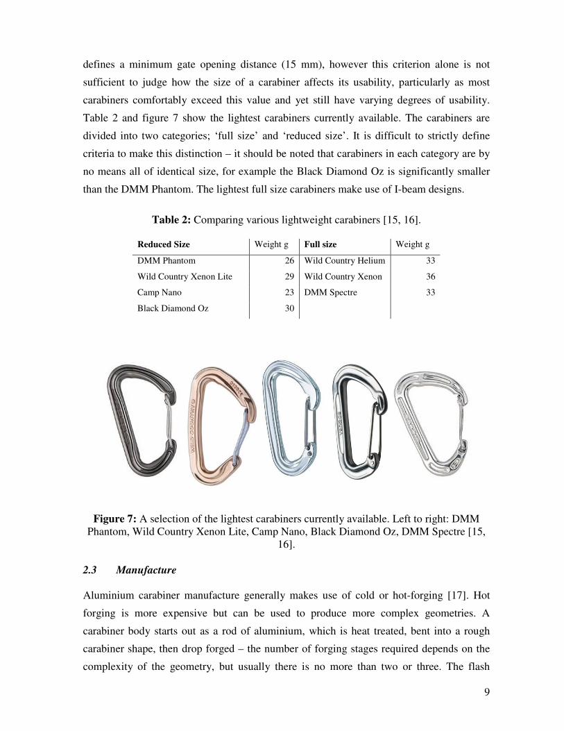
Table 2 and figure 7 show the lightest carabiners currently available. The carabiners are
divided into two categories; ‘full size’ and ‘reduced size’. It is difficult to strictly define
criteria to make this distinction – it should be noted that carabiners in each category are by
no means all of identical size, for example the Black Diamond Oz is significantly smaller
than the DMM Phantom. The lightest full size carabiners make use of I-beam designs.
Table 2: Comparing various lightweight carabiners [15, 16].
Reduced Size Weight g Full size Weight g
DMM Phantom 26 Wild Country Helium 33
Wild Country Xenon Lite 29 Wild Country Xenon 36
Camp Nano 23 DMM Spectre 33
Black Diamond Oz 30
Figure 7: A selection of the lightest carabiners currently available. Left to right: DMM
Phantom, Wild Country Xenon Lite, Camp Nano, Black Diamond Oz, DMM Spectre [15,
16].
2.3 Manufacture
Aluminium carabiner manufacture generally makes use of cold or hot-forging [17]. Hot
forging is more expensive but can be used to produce more complex geometries. A
carabiner body starts out as a rod of aluminium, which is heat treated, bent into a rough
carabiner shape, then drop forged – the number of forging stages required depends on the
complexity of the geometry, but usually there is no more than two or three. The flash

10
(excess material expelled during forging) must be cut off and then finally the carabiner is
polished and anodized.
Figure 8: A few stages of carabiner manufacture; a rod of aluminium is bent into shape,
forged, then the flash is cut off [17].
3 Design criteria
As a legal requirement all carabiners intended for climbing, sold in the EU, must adhere to
EN standards, furthermore, the EN standard is generally considered a minimum and most
carabiners exceed the requirements. Detailed design criteria are defined below, these are
divided into two categories – strict requirements and design guidelines. The requirements
consist of quantifiable values for load ratings and dimensions (based on the standards), and
any other quantifiable properties (such as operating temperatures). The design guidelines
are harder to quantify, more like design advice, which is still very important (e.g. does the
carabiner tend to relocate the rope to transmit most of the force through the spine?). For
conciseness the requirements which are based on the standards are defined only roughly
here, these are marked with an asterisk*, for stricter definitions of these requirements
please see EN 12275 [6]. The final part of this section describes additional testing carried
out by Black Diamond that goes beyond the requirements of the standards.
3.1 Requirements
For bolt, piton and belay device compatibility the cross section of the carabiner at any point
must fit inside a 13 mm diameter circle.
11
The gate opening clearance should be at least 15 mm when the gate is fully open*.
The gate should be spring loaded so that it closes automatically and requires a force of at
least 5N to open*.
The gate should not be obstructed when two 11 mm ropes are clipped inside the carabiner
and are resting on the short or long arm*.
When force of 800 N is applied in longitudinal tension, the carabiner must not plastically
deform such that it can no longer be opened by hand and the gate must remain operational
(able to open by hand) whilst the force is applied*.
The carabiner must not break when a force of 20 kN is applied longitudinally.*
The carabiner must not break when a force of 7 kN is applied transversely.*
The carabiner must not break when a force of 7 kN is applied longitudinally with the gate
open.*
All of the above requirements must be satisfied in operating temperatures from -40 to
+60°C.
3.2 Design guidelines
It is expected that a composite carabiner will cost more than one made from aluminium,
nevertheless, the carabiner should be economically viable to manufacture and sell.
The carabiner material should be sufficiently tough to withstand the impact of a climbing
fall.
The carabiner material should have sufficiently low friction against a sliding rope that
frictional heating does not bring the carabiner out of its operating temperature range.
The carabiner material should not adsorb excessive moisture such that is adversely affects
its operation or strength.
The carabiner should be resistant to salt water, mild acids and alkalis, UV radiation, and
have good resistance to chemical corrosion and degradation.
There should be sufficient space to tie a clove hitch [18], using an 11 mm rope, on the long
arm of the carabiner without restricting the gate movement.
The arms of the carabiner should be at an acute angle to the spine such that the rope tends
to slide towards the spine, reducing bending.*
The radius of curvature of the surface that the rope slides over is recommended to be at
least 4.5 mm over an angle of 120°.*
The hook or other gate binding mechanism on the inside of the nose of the carabiner should
not unduly snag on the rope when it is clipped or unclipped.
12
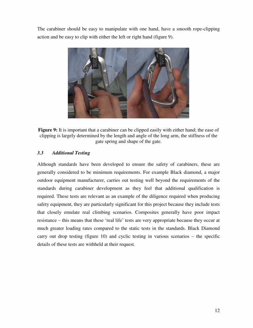
The carabiner should be easy to manipulate with one hand, have a smooth rope-clipping
action and be easy to clip with either the left or right hand (figure 9).
Figure 9: It is important that a carabiner can be clipped easily with either hand; the ease of
clipping is largely determined by the length and angle of the long arm, the stiffness of the
gate spring and shape of the gate.
3.3 Additional Testing
Although standards have been developed to ensure the safety of carabiners, these are
generally considered to be minimum requirements. For example Black diamond, a major
outdoor equipment manufacturer, carries out testing well beyond the requirements of the
standards during carabiner development as they feel that additional qualification is
required. These tests are relevant as an example of the diligence required when producing
safety equipment, they are particularly significant for this project because they include tests
that closely emulate real climbing scenarios. Composites generally have poor impact
resistance – this means that these ‘real life’ tests are very appropriate because they occur at
much greater loading rates compared to the static tests in the standards. Black Diamond
carry out drop testing (figure 10) and cyclic testing in various scenarios – the specific
details of these tests are withheld at their request.

13
Figure 10: An example of a drop tower used to test climbing equipment. Reproduced from
[19].
4 Materials
Types of composites in use today include Metal matrix composites, Ceramic matrix
composites, Carbon matrix composites, Polymer matrix composites and Hybrid composite
materials. There may be potential for other types of composites to be used in a carabiner,
however, most successful aluminium to composite transitions, where weight reduction is
the aim, have made use of fibre-reinforced polymer matrix composites (e.g. bicycles, sports
rackets, aerospace structures etc.). It is not feasible to cover every option in the scope of
this project; therefore the focus will be on fibre-reinforced polymer matrix composites
only.
This section will explore the material options for the fibres and the matrix, these options
will be measured against the criteria set out in the previous section. The ideal material
combination will have the highest strength to weight ratio, a good stiffness to weight ratio
and will satisfy the requirements above. Properties of aluminium 7075 T6 are given below
(table 3) as a benchmark for comparison. The properties of a composite depend on the
combined properties and interaction of the matrix and reinforcement; it is not possible to
predict the properties of a composite based on the material properties of the constituent
parts alone. This is because the final properties of the composite also depend on the
processing conditions, the method of manufacture, the geometry and preparation of the

14
fibres (this dictates the properties of the matrix/fibre interface) however, some aspects of
the contribution of each part to the overall properties can be separated.
Table 3: Properties of aluminium 7075 T6 [20-22].
Young's modulus 72 GPa
Tensile strength 510 MPa
Yield stress 434 MPa
Fracture toughness, KIC 25 MPa.m1/2
Density 2810 kg/m3
Price (approximate for 7075-T651) 8 £/kg
4.1 Fibres
In a fibre reinforced polymer (FRP) the reinforcement fibres are generally very strong, stiff
materials. Their high tensile strength comes from their molecular orientation and small
cross section, typically carbon fibres have a diameter between 4 and 11 µm [23]. Due to
their small diameter the maximum defect size in fibres is much smaller than in their
monolithic counterparts. In very stiff materials, where failure is caused by brittle fracture,
strength is largely determined by the size of defects present. Therefore reducing the
maximum defect size will significantly increase strength; however, as they are so small and
brittle they are vulnerable to damage. During processing and handling fibres can become
damaged due to abrasion. In an FRP the fibres are protected from abrasion and
environmental effects by the surrounding matrix. The matrix gives the composite its
durability, shape and appearance, whilst the fibres dictate the overall stiffness and strength.
Table 4: Properties of composite reinforcing fibres [24]. In order; tensile modulus, failure
stress, failure strain, density, specific modulus, specific strength.
15
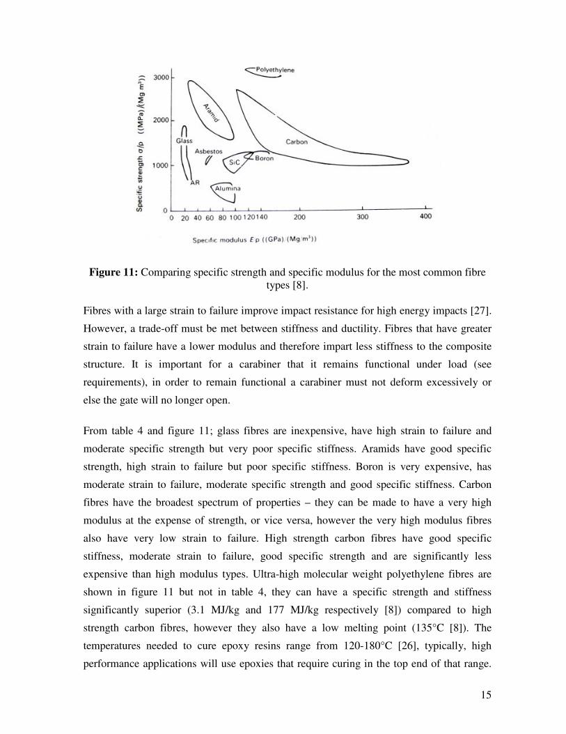
Figure 11: Comparing specific strength and specific modulus for the most common fibre
types [8].
Fibres with a large strain to failure improve impact resistance for high energy impacts [27].
However, a trade-off must be met between stiffness and ductility. Fibres that have greater
strain to failure have a lower modulus and therefore impart less stiffness to the composite
structure. It is important for a carabiner that it remains functional under load (see
requirements), in order to remain functional a carabiner must not deform excessively or
else the gate will no longer open.
From table 4 and figure 11; glass fibres are inexpensive, have high strain to failure and
moderate specific strength but very poor specific stiffness. Aramids have good specific
strength, high strain to failure but poor specific stiffness. Boron is very expensive, has
moderate strain to failure, moderate specific strength and good specific stiffness. Carbon
fibres have the broadest spectrum of properties – they can be made to have a very high
modulus at the expense of strength, or vice versa, however the very high modulus fibres
also have very low strain to failure. High strength carbon fibres have good specific
stiffness, moderate strain to failure, good specific strength and are significantly less
expensive than high modulus types. Ultra-high molecular weight polyethylene fibres are
shown in figure 11 but not in table 4, they can have a specific strength and stiffness
significantly superior (3.1 MJ/kg and 177 MJ/kg respectively [8]) compared to high
strength carbon fibres, however they also have a low melting point (135°C [8]). The
temperatures needed to cure epoxy resins range from 120-180°C [26], typically, high
performance applications will use epoxies that require curing in the top end of that range.
16
Commonly used thermoplastic matrices require even higher processing temperatures, for
example polyimide has a melting point of around 375°C, polyamide of around 240°C and
PEEK of 322°C [25]. Although they have remarkable properties, polyethylene fibres are
not compatible with the high temperatures required for most polymer based composite
processing.
4.2 Matrix
In a composite the matrix acts to transfer the load to the reinforcing fibres, it tends to be far
less stiff than the reinforcement (usually by more than an order of magnitude), therefore it
does not carry a significant part of the load. The matrix affects interlaminar shear strength
which is crucial for applications where there will be bending loads [26]. In discontinuous
fibre composites the ability of the matrix to transfer loads is more critical. The matrix
determines the environmental resistance, friction/wear properties and has a significant
effect on the toughness of a composite [27]. According to the design criteria the carabiner
matrix material should be tough, low friction and resist water, salt water, UV radiation,
mild acid, alkali and other chemical attacks. Ideally it should also be reasonably
inexpensive.
When it comes to polymer matrices there are two categories to choose from, thermoset or
thermoplastic (rubbers are inappropriate for a carabiner). By definition the difference
between the two is simply that, due to cross linking between molecules, thermosets cannot
be re-melted and reprocessed once they have been cured. Thermosets generally have a low
viscosity before they are cured, whilst thermoplastic melts have very high viscosity. This
makes it difficult to properly impregnate the reinforcement fibres – usually requiring high
pressure and temperature. Broadly speaking thermosets are stiffer, are more resistant to
chemical attack and can maintain their properties at higher temperatures (table 5) due to
cross-linking. However, cross-linking raises their glass transition temperature above room
temperature – making them brittle.
The choice of matrix strongly affects the threshold energy for impact damage [27];
furthermore the threshold energy is not affected by the type or layout of the fibres. As a
result it is very important to use a tough matrix. Thermoset matrices, such as epoxy, can be
toughened with rubber particles. However epoxies are susceptible to UV degradation and
also adsorb moisture – which decreases their physical properties.
17
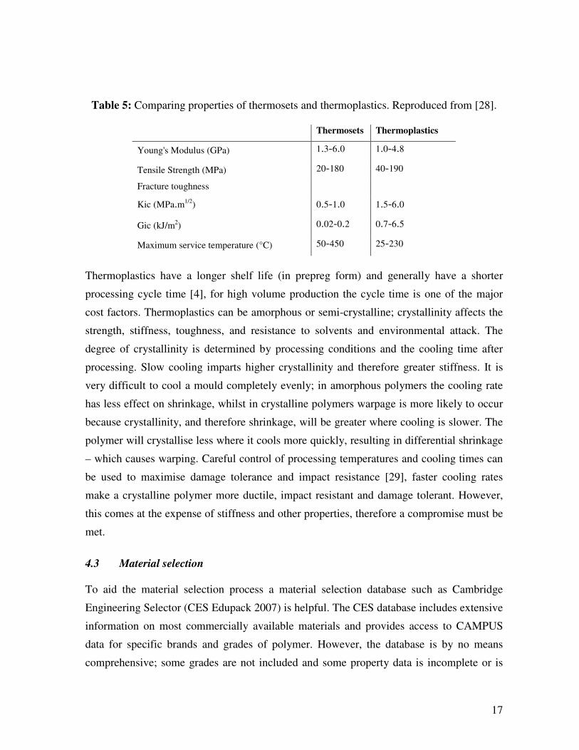
Table 5: Comparing properties of thermosets and thermoplastics. Reproduced from [28].
Thermosets Thermoplastics
Young's Modulus (GPa) 1.3-6.0 1.0-4.8
Tensile Strength (MPa) 20-180 40-190
Fracture toughness
Kic (MPa.m1/2) 0.5-1.0 1.5-6.0
Gic (kJ/m2) 0.02-0.2 0.7-6.5
Maximum service temperature (°C) 50-450 25-230
Thermoplastics have a longer shelf life (in prepreg form) and generally have a shorter
processing cycle time [4], for high volume production the cycle time is one of the major
cost factors. Thermoplastics can be amorphous or semi-crystalline; crystallinity affects the
strength, stiffness, toughness, and resistance to solvents and environmental attack. The
degree of crystallinity is determined by processing conditions and the cooling time after
processing. Slow cooling imparts higher crystallinity and therefore greater stiffness. It is
very difficult to cool a mould completely evenly; in amorphous polymers the cooling rate
has less effect on shrinkage, whilst in crystalline polymers warpage is more likely to occur
because crystallinity, and therefore shrinkage, will be greater where cooling is slower. The
polymer will crystallise less where it cools more quickly, resulting in differential shrinkage
– which causes warping. Careful control of processing temperatures and cooling times can
be used to maximise damage tolerance and impact resistance [29], faster cooling rates
make a crystalline polymer more ductile, impact resistant and damage tolerant. However,
this comes at the expense of stiffness and other properties, therefore a compromise must be
met.
4.3 Material selection
To aid the material selection process a material selection database such as Cambridge
Engineering Selector (CES Edupack 2007) is helpful. The CES database includes extensive
information on most commercially available materials and provides access to CAMPUS
data for specific brands and grades of polymer. However, the database is by no means
comprehensive; some grades are not included and some property data is incomplete or is
18
provided as an estimate only. Nonetheless, CES is useful as a guide to aid the selection
process.
CES allows limits to be applied to a large range of material properties. In addition it can
compare materials by graphical means such as Ashby charts. Property limits can be used to
systematically reduce the polymer database to a suitable shortlist of materials. By varying
the values of important criteria a general idea of what is a ‘high’ or ‘low’ value can be
obtained. This process involves raising the requirement of a property, whilst leaving all
other properties without any requirements, to the point where the number of materials that
pass the limit become small (one or two materials). In this way the highest possible
expectation of each desired property can be found. Once the highest possible expectations
are found, they can be entered into CES and gradually relaxed until a suitable number of
materials passed the limits. An appropriate material can then be chosen from this shortlist.
Specific details of the selection criteria and process are described below.
First, the CES database was set to use polymeric materials only, this includes both pure
polymers and polymer based composites (in both continuous fibre laminate and short
random fibre forms). Initially, no limit was set on toughness, in this way the maximum
feasible value can be ascertained when all other criteria are set to minimum acceptable
values. CES uses five descriptive classes to judge the environmental resistance and
durability of polymers; the classes are: very poor, poor, average, good and very good. In
agreement with the design guidelines set out in the design criteria section a ‘very good’
requirement was set on the following durability criteria: fresh water, salt water, weak acid,
weak alkali, organic solvents and UV radiation. In addition, the maximum service
temperature was set to be at least 60°C and the minimum service temperature was set to be
at most -40°C. Table 6 summarises these selection criteria. These requirements cut down
the number of passable materials in the CES database from 637 to 25.

19
Table 6: Selection criteria used in CES to make a shortlist of passable materials.
Criteria Requirement
Fresh water resistance Very good
Salt water resistance Very good
Weak acid resistance Very good
Weak alkali resistance Very good
Organic solvent resistance Very good
UV radiation resistance Very good
Maximum service temperature ≥ 60 °C
Minimum service temperature ≤ -40 °C
The next step was to optimise the toughness by setting further limits. In CES both fracture
toughness ICK and notched impact energy (Izod) are used to define room temperature
toughness. Izod energy gives a way of approximately ranking materials by critical strain
energy release rate ICG , but the ratio of ICK and ICG depends on stiffness (eq. 1) [30].
)1/( 22vEGK ICIC −= (Equation 1)
Where E is Young’s modulus and ν is Poisson’s ratio. Polymers in general have a relatively
low stiffness, therefore using ICG (based on Izod) alone may not be a good indication of
toughness. For this reason ICK was also included in the selection criteria. This will ensure
that polymers with a high Izod toughness but disproportionately low fracture toughness
(due to low modulus) will not be able to pass the limits.
First, by trial and error, the limit was found for fracture toughness that allowed through
only the top 50% (i.e. 12 results) of the 25 previously passable materials – the value found
was 5.5 MPa.m1/2
. This limit was then removed and, by the same means, the corresponding
value for Izod impact strength was found to be 25 kJ/m2. Finally, both of these limits were
applied simultaneously. The final seven passing results (table 7) consisted of various forms
of PEEK based composite, two ETFE based materials, unfilled ECTFE and random
oriented glass fibre filled polyester liquid crystal.

20
Table 7: The final 7 results that passed the CES selection criteria set out in table 6, plus
these additional; a KIC of at least 5.5 MPa.m1/2
and a notched Izod of at least 25 kJ/m2.
Further increases in the toughness requirements led to all materials being excluded apart
from the carbon fibre PEEK composite laminates. However, it is not necessarily fair to
exclude the other materials from consideration because they are in the unfilled form or
filled with random short fibres, whilst the PEEK is filled with unidirectional continuous
fibres. It is not obvious whether the excluded materials would be better or worse as there
are no laminate forms of ETFE, ECTFE or PLC available in the database. The fact that
they don’t exist in that form may suggest that either, due to incompatibility with fibres, it is
difficult to produce, or the resulting properties are not very desirable. Otherwise it is
possible that it has simply been overlooked.
The list of materials in table 7 has been produced using criteria for the matrix only, it is
also important to consider the strength and stiffness requirements. Those materials in the
list that are unfilled and those with short random oriented fibres would have to be
combined with continuous reinforcements to attain the necessary strength and stiffness.
However, using any of the listed matrix materials in combination with a high volume
fraction (50-60%) of intermediate modulus carbon fibres will produce a material that
exceeds the specific strength and stiffness of current carabiner material by a large margin.
The challenge comes in finding the optimum combination of materials to maximise
toughness. This section has studied the available materials with a view to finding materials
that satisfy the toughness, strength, durability and other requirements defined previously.
Material combinations in relation to the available manufacturing processes will be
considered in the design section later. The next section describes the range of available
composite manufacturing methods and relates them to the design criteria and requirements.

21
5 Manufacturing processes
A major pitfall, when moving from metal to composite design, is neglecting manufacturing
considerations at the outset. Metals are largely isotropic and their properties are generally
easier to predict, therefore it is less important to think about manufacturing considerations
whilst in the material selection and design stages. However, with composites this can lead
to major problems because material selection, design and manufacture all go hand in hand.
Choosing one material over another could have a massive impact in terms of possible
design geometries and manufacturing options.
The basic requirement of all composite manufacturing processes is to maintain the desired
pressure and temperature throughout the component over the required period of time [23].
If the temperature and pressure are controlled effectively, and the matrix and fibres are held
in position until the composite becomes cool enough (or has set sufficiently in the case of
thermosets) to be ejected, then manufacture will be successful. Manufacturing processes
can be split into two categories; open mould and closed mould. In the open mould category
there are wet lay-up processes, bag moulding and curing processes, and autoclave
moulding processes. In the closed mould category there is transfer moulding, compression
moulding and injection moulding. Another manufacturing process, which does not fit into
either category, is filament winding. Several of these processes are compared in figure 12.
Figure 12: Comparing the performance of composite manufacturing processes.
Reproduced from [4].
22
5.1 Open mould processes
Wet lay-up processes involve either hand lay-up or spray-up; in either case impregnation
occurs during the moulding process. Hand lay-up is a skilled process and therefore labour
is expensive, however the cost of the mould and other capital investments are usually fairly
low. This makes it suited to short-run components, where a fast cycle time is not
imperative, such as boat hulls. Spray-up cannot achieve high a volume fraction – therefore
it is not suitable for high performance lightweight applications. Both spray-up and hand
lay-up are most suited to large sheet-like components such as boat hulls and furniture.
Unlike other processes they require little or no pressure.
Bag moulding is essentially an extension to the lay-up process; the lay-up mixture is
covered in a flexible airtight bag and either an external pressure is applied or a vacuum is
created inside the bag-mould enclosure. This improves the properties of the resultant
composite by driving out volatile substances and increasing the volume fraction of
reinforcement.
Autoclave moulding uses a combination of a vacuum bag and a pressure chamber to
produce components with high geometrical complexity and very good mechanical
properties. Almost invariably it is prepregs that are used in autoclave moulding (although
dry filament windings can also be cured in an autoclave), the moulding cycle can take
many hours.
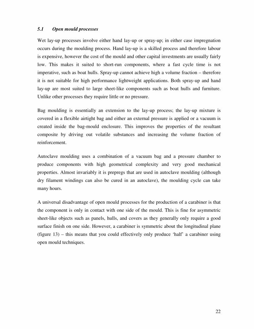
A universal disadvantage of open mould processes for the production of a carabiner is that
the component is only in contact with one side of the mould. This is fine for asymmetric
sheet-like objects such as panels, hulls, and covers as they generally only require a good
surface finish on one side. However, a carabiner is symmetric about the longitudinal plane
(figure 13) – this means that you could effectively only produce ‘half’ a carabiner using
open mould techniques.

23
Figure 13: Open mould processes only allow the component to contact the mould on one
side – which means the other side will be flat and have a relatively poor surface finish.
In all processes that use laminates there are a number of options to consider in terms of the
form of the reinforcement fibres. There are both unidirectional and woven fabric options.
Unidirectional options include: tape, single tows, strips and unidirectional fabrics (defined
as having greater than 80% warp). Woven fabrics include: balanced fabrics and multiaxials.
Figure 14 describes the effects of using different fibre forms.

24
Figure 14: Comparison chart for laminate fibre reinforcement forms [4].
5.2 Closed mould processes
In transfer moulding a closed mould contains pre-placed fibre layers and is filled with
liquid resin at low pressure. Transfer moulding makes use of thermosets only, the low
viscosity of the uncured thermoset resin means that pressure requirements are low;
consequently tooling costs can be kept low. Transfer moulding is generally used for high
strength and high stiffness components with production in the tens of thousands – as such it
is a definite candidate for carabiner manufacture. A three dimensional fibre preform, with
25
fibres oriented optimally for the tensile and bending loads expected in a carabiner, could be
infused with a suitably tough resin.
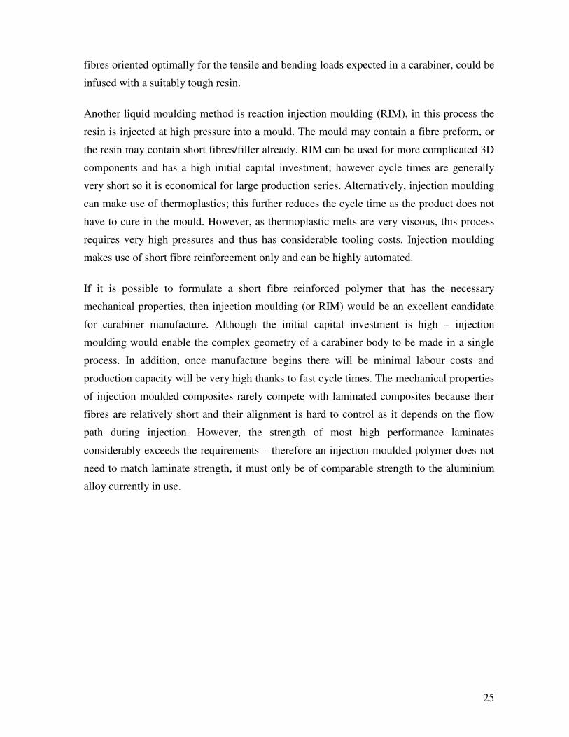
Another liquid moulding method is reaction injection moulding (RIM), in this process the
resin is injected at high pressure into a mould. The mould may contain a fibre preform, or
the resin may contain short fibres/filler already. RIM can be used for more complicated 3D
components and has a high initial capital investment; however cycle times are generally
very short so it is economical for large production series. Alternatively, injection moulding
can make use of thermoplastics; this further reduces the cycle time as the product does not
have to cure in the mould. However, as thermoplastic melts are very viscous, this process
requires very high pressures and thus has considerable tooling costs. Injection moulding
makes use of short fibre reinforcement only and can be highly automated.
If it is possible to formulate a short fibre reinforced polymer that has the necessary
mechanical properties, then injection moulding (or RIM) would be an excellent candidate
for carabiner manufacture. Although the initial capital investment is high – injection
moulding would enable the complex geometry of a carabiner body to be made in a single
process. In addition, once manufacture begins there will be minimal labour costs and
production capacity will be very high thanks to fast cycle times. The mechanical properties
of injection moulded composites rarely compete with laminated composites because their
fibres are relatively short and their alignment is hard to control as it depends on the flow
path during injection. However, the strength of most high performance laminates
considerably exceeds the requirements – therefore an injection moulded polymer does not
need to match laminate strength, it must only be of comparable strength to the aluminium
alloy currently in use.
26
Figure 15: A schematic diagram of the thermoset injection moulding process [1].
Compression moulding involves using a compression press to apply heat and pressure to a
sheet or bulk moulding compound. The heated moulding compound flow into the shape of
the mould and usually produces sheet-like components. Cycle times are generally low and
the process is often used in the automotive industry to produce covers and housings.
Prepregs and laminates can also be used in a compression moulding process – generally
giving the resulting product better mechanical properties. Rubber-block and hydro forming
techniques enables more complex geometries and reduce the risk of wrinkles in the
component. Compression moulding is certainly a possible candidate for carabiner
production. A roughly carabiner shaped charge pattern would be cut from a sheet moulding
compound such that it would cover near to 90% of the mould surface. A charge would
normally cover somewhere between 20 and 90% of the surface – covering a larger portion
of the surface is beneficial for structural applications because it keeps flow induced
orientation to a minimum.
Filament winding is the process of wrapping a tow or band of fibres around a rotating
mandrel. Either prepreg fibres are used or fibres are dipped in wet resin as they are wound.
The winding angle and pattern can be tailored to the loading requirements and a high fibre
volume fraction is possible which means parts generally have good mechanical properties.
However, shapes with reverse curves cannot be wound, in addition, winding is effectively
limited to parts with rotational symmetry. This makes it difficult to use in carabiner
manufacture as the carabiner shape precludes the use of normal filament winding

27
apparatus. A radical redesign of the carabiner shape may enable the use of filament
winding.
Another composite manufacturing process that may be worth considering it that used for
tennis racket production. A carbon fibre prepreg is wrapped around an inflatable tube; the
tube and prepreg are then inserted into a closed mould. The tube is pressurised and the
mould is heated until the racket consolidates [31]. This produces strong and lightweight
rackets that can not only withstand the impact of a tennis ball travelling at 140 mph – but
can also send the ball hurtling in the opposite direction at a similar speed. This process
could be adapted for carabiner manufacture. It would require the carabiner to be hollow
which could potentially increase the cross section beyond the maximum acceptable value –
this depends on what the minimum possible size is for an inflatable tube capable of
applying the required pressure.
The variety of composite manufacturing processes reflects the variety and complexity of
composite materials. The composite field is continuously changing - new combinations of
materials are frequently created whilst new variations and modifications to existing
manufacturing methods are introduced.
6 Literature Research
Design limits for composites tend to be much lower than their capability due to poor impact
strength [8]. Improving toughness will reduce the need for excessive safety factors and thus
enable a great reduction in weight for high performance composite products. For this
reason there is a large body of literature focusing on methods to improve composite
toughness. The aim of this literature research is to find the relative effectiveness of all the
available toughening methods and to determine which methods are most appropriate for
each manufacturing process. Further aims include finding novel production processes and
fibre/matrix combinations that yield good strength, stiffness and toughness. This
knowledge will inform later design decisions. 108 papers were categorised, of which 95
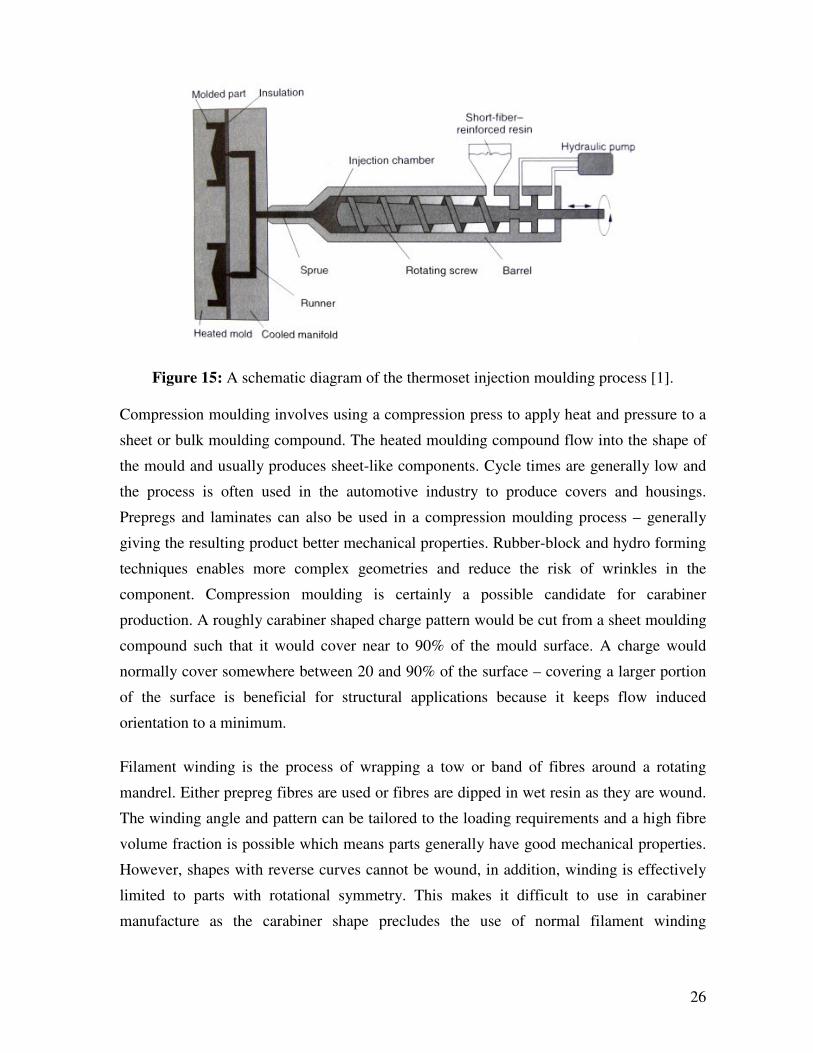
have been summarised. Figure 16 shows a diagram of the category breakdown with the
number of papers in each area. The literature review is summarised below.
28
Figure 15: A summary of research categories relevant for composite materials in rock
climbing.
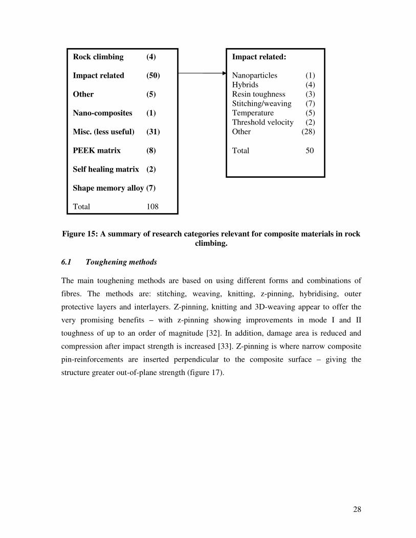
6.1 Toughening methods
The main toughening methods are based on using different forms and combinations of
fibres. The methods are: stitching, weaving, knitting, z-pinning, hybridising, outer
protective layers and interlayers. Z-pinning, knitting and 3D-weaving appear to offer the
very promising benefits – with z-pinning showing improvements in mode I and II
toughness of up to an order of magnitude [32]. In addition, damage area is reduced and
compression after impact strength is increased [33]. Z-pinning is where narrow composite
pin-reinforcements are inserted perpendicular to the composite surface – giving the
structure greater out-of-plane strength (figure 17).
Rock climbing (4)
Impact related (50)
Other (5)
Nano-composites (1)
Misc. (less useful) (31)
PEEK matrix (8)
Self healing matrix (2)
Shape memory alloy (7)
Total 108
Impact related:
Nanoparticles (1)
Hybrids (4)
Resin toughness (3)
Stitching/weaving (7)
Temperature (5)
Threshold velocity (2)
Other (28)
Total 50
29
Figure 17: Z-pins visible after pullout [34].
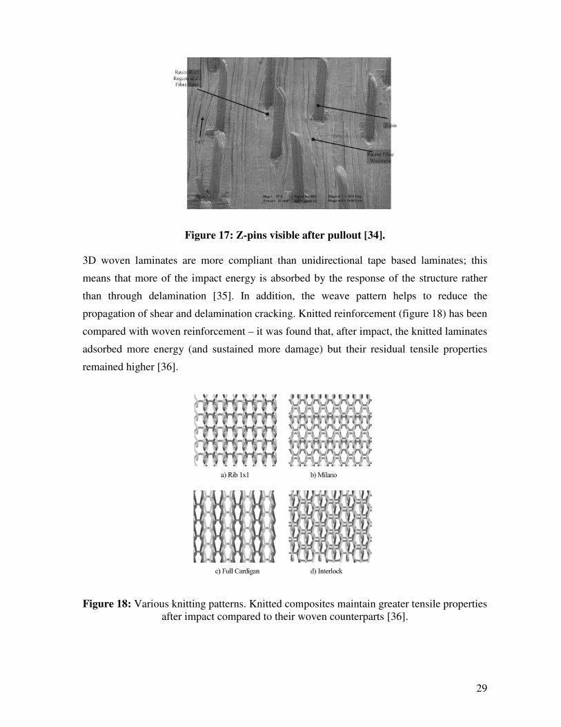
3D woven laminates are more compliant than unidirectional tape based laminates; this
means that more of the impact energy is absorbed by the response of the structure rather
than through delamination [35]. In addition, the weave pattern helps to reduce the
propagation of shear and delamination cracking. Knitted reinforcement (figure 18) has been
compared with woven reinforcement – it was found that, after impact, the knitted laminates
adsorbed more energy (and sustained more damage) but their residual tensile properties
remained higher [36].
Figure 18: Various knitting patterns. Knitted composites maintain greater tensile properties
after impact compared to their woven counterparts [36].

30
6.2 Matrix
The toughness of the matrix material has been shown to have a very strong influence on the
toughness of the composite [37, 38]. Using a tougher matrix increases the damage initiation
load by increasing GIIC.
Using a toughening agent, for example rubber particle toughening, would normally
improve toughness at the expense of stiffness. Adding alumina nanoparticles to an epoxy
resin can improve both toughness and stiffness [39]. Adding 1-2% alumina particles was
shown to introduce new energy dissipating mechanisms – shear yielding of the matrix,
particle pullout and crack pinning. Adding calcium silicate microparticles into the
nanoparticle composite improved wear resistance by a factor of three, the impact energy
stayed above that for the neat matrix but the strain to break decreased significantly.
6.3 Fibre
Combining different types of fibre in a composite is called hybridization. The aim of
hybridization is generally to combine two types of fibres, with very different properties, to
attain the benefits of both. For example, a high modulus fibre might be used in combination
with tougher fibres to give a composite both stiffness and impact resistance. It has been
shown that, in laminated composite, alternating layers of glass and carbon fibre reduces
notch sensitivity compared to pure glass or pure carbon fibre laminates [55]. The effect is
amplified if the layers are ordered such that carbon fibre is on the outside. Furthermore, this
layering improves the compressive strength after impact as the damage area and crack
lengths are reduced.
For woven hybrid composites it has been shown that interply are tougher than intraply
hybrids in low velocity impact [40]. In an interply hybrid each layer containing only one
fibre type – but fibre types alternate in successive layers. In an intraply hybrid each layer
contains a mixture of both fibre types. The interply hybrid showed a 9-67% higher specific
energy adsorption, a 5-45% lower peak load and an 8-220% higher ductile index.
Hybridization in random oriented short fibre reinforced composites has been shown to
significantly improve tensile strength and modulus, flexural strength and modulus and
marginally improve toughness [41]. Thermotropic liquid crystalline polymer (TLCP) fibres
were added to a carbon fibre reinforced PEEK matrix (figure 19), the TLCP fibres were

31
around an order of magnitude smaller than the carbon fibres (0.3-1.5 µm compared to 7
µm). The TLCP fibres also reduced the melt viscosity – enabling easier processing.
Figure 19: Adding smaller TLCP fibres to a short fibre reinforced matrix improves
mechanical and processing properties [41].
Short shaped copper fibres have been shown to improve toughness [42]. Shaping the fibres
affects the fibre/matrix interface and, when combined with a tough matrix, shaped fibres
perform better than their straight equivalents. Another toughening method, which makes
use of interlaminar fibres, has been shown to reduce damage area and severity [43, 44].
Short fibres are sprinkled in between layers before curing; this increases the out of plane
strength.
The volume fraction of fibres is a major determining factor for composite mechanical
properties. For injection moulded polypropylene, with long discontinuous glass fibre
reinforcement, there is an optimum percentage of reinforcement for maximising strength
and toughness [45]. Stiffness was found to increase linearly with fibre content up to the
maximum possible of 73% weight; whilst the maximum content for strength and toughness
was found to be 40-50% weight.
6.4 Processing
Consolidation temperature and cooling rates have been shown to affect toughness [46-48,
49]. Rapid cooling increases matrix toughness but reduces tensile strength due to reduced
crystallinity – a compromise must be met to achieve sufficient strength whilst optimising
toughness. Similarly, a lower consolidation temperature increases matrix ductility –
improving composite toughness.

32
The properties of the interphase (the region of resin close to the reinforcement fibres) can
be very different to those of the bulk resin [50]. The interphase plays a crucial role in
determining the overall strength and toughness of a composite. Its properties can be
tailored to optimise strength and toughness by using appropriate sizings (surface treatment
on the glass fibres) to affect the fibre/matrix bond.
7 Design
Design using composite materials is a complicated process; matching up the requirements
of a design brief with the offerings of materials and the limitations of a compatible
manufacturing process is like threading a moving needle. Material combinations are
endless, research is wide-ranging, rapid and continuous and manufacturing options are
numerous and ever-changing. The flexibility of composite manufacture is such that new
production methods are often invented, or existing ones modified, to better suite a specific
application. Before the design process could begin a substantial amount of research into
composite materials, design and manufacture was necessary. This research was intended to
help determine the optimal method of creating a carabiner from composites.
7.1 Initial exploration
The feasibility of the project was tested with a number of preliminary calculations. Several
calculators were created, using Microsoft Excel, to expedite the exploratory calculations.
The first set of calculators used simple stress analysis to estimate the ultimate tensile stress,
diameter or strength rating of a carabiner (any one of these properties can be found if the
other two are defined). To simplify the calculations it was assumed that the carabiner cross
section was circular and that carabiners fail in pure tension (i.e. ignoring the bending
contribution due to the applied load being offset from the longitudinal axis of the spine).
The error in the latter assumption is described further in the Testing and FEA section later.
By measuring the diameter of a carabiner (or approximating its area by other means), then
inputting its strength rating – the design stress can be estimated, this is useful when
considering new designs.
Further calculators were created to estimate: the bending stress in the spine when loaded
transversely, the weight of a carabiner based on its straightened length, diameter and
density, the number of fibre tows needed to achieve a certain strength rating and the
volume fraction based on the number of fibre tows used. The assumption of circular cross

33
section means that these calculators are only very rough estimates, useful for quick
comparisons and ‘ball-park’ figures. Using these calculators, combined with data on
material properties, enables an estimate of how much weight can be saved with various
material combinations. An estimate of the maximum weight saving potential can be
determined by comparing the specific strengths of a typical high strength laminate and
7075 T6 aluminium:
(Equation 2)
(Equation 3)
Where m is the mass of the carabiner body, L is its straightened length, is the stress due
to an applied longitudinal load F, A is the cross-section area (the carabiner body is assumed
to have constant cross-section) and ρ is the density of the carabiner material. Combining
equation 2 and 3:
(Equation 4)
Equation 4 describes how the minimum mass required to make a carabiner body of
sufficient strength depends only on the specific strength of the material, the load that it will
have to carry and its straightened length. As mentioned previously, this assumes that the
carabiner material fails in pure tension. Using CF/cyanate ester quasi-isotropic laminate as
typical example: composite laminate density ρc is 1670 kg/m3 and the tensile strength σc is
607 MPa [51]. A quasi-isotropic laminate was chosen because in reality a carabiner will
need to take tensile, compressive and bending loads in both the transverse and longitudinal
directions – therefore using the tensile strength of unidirectional laminate would give
overly optimistic predictions. From table 3; the density ρa and strength σa for 7075 T6
aluminium are 2810 kg/m3 and 510 MPa respectively. Based on a typical body length of
19.5 cm and an applied load of 24 kN the mass of the carabiner body will be 13 g and 26 g
for composite and aluminium respectively (table 8). Based on a wiregate mass of 6 g, this
comes to a maximum percentage weight saving of 40%. This is only a very rough guide to
the maximum weight saving possible, realistically it is likely that a composite carabiner
must be over-designed somewhat to improve impact resistance.
34
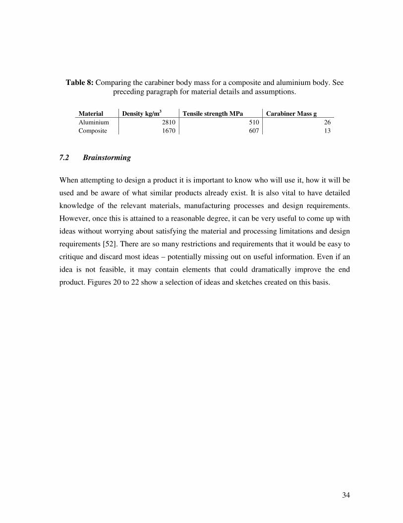
Table 8: Comparing the carabiner body mass for a composite and aluminium body. See
preceding paragraph for material details and assumptions.
Material Density kg/m3 Tensile strength MPa Carabiner Mass g
Aluminium 2810 510 26
Composite 1670 607 13
7.2 Brainstorming
When attempting to design a product it is important to know who will use it, how it will be
used and be aware of what similar products already exist. It is also vital to have detailed
knowledge of the relevant materials, manufacturing processes and design requirements.
However, once this is attained to a reasonable degree, it can be very useful to come up with
ideas without worrying about satisfying the material and processing limitations and design
requirements [52]. There are so many restrictions and requirements that it would be easy to
critique and discard most ideas – potentially missing out on useful information. Even if an
idea is not feasible, it may contain elements that could dramatically improve the end
product. Figures 20 to 22 show a selection of ideas and sketches created on this basis.

35
Figure 20: Brainstorming ideas.
Top – a double axis gate that
enables the gate to open in the
clockwise and anticlockwise
directions. The gate could be split
in two; each side rotate
independently. Alternatively a
mechanism could be used that sets
the rotation axis depending on
whether the user applies an opening
force on the top or bottom of the
gate.
Bottom – a carabiner could be cut
from a panel. The panel could be
made using thermoplastic prepreg
compression moulding. The prepreg
could be made by automatic lay-up
to orient the fibre strips optimally.
Figure 21: Brainstorming ideas.
Top – some existing carabiners
make use of a fixed sling, where the
sling, used to attach two carabiners
together to make a quickdraw,
cannot be removed. This is
potentially useful for a composite
carabiner as, in accordance with the
EN standard, it circumvents the
need to pass the transverse loading
requirements. This means that
loading directions are more
predictable which makes it easier to
take advantage of the excellent
tensile properties of reinforcement
fibres.
Bottom - a sliding gate would lessen
the chances of accidental gate
opening.

36
Figure 22: Brainstorming ideas. Left – various alternatives for a single part design. If the
carabiner used a single part design it could be injection moulded in a single process –
greatly simplifying manufacturing and reducing labour costs. Right – exploring different
arm angles and spines lengths to encourage rope relocation and ease clipping.
7.3 Proposed designs
Two proposed design options are described below. These combine the most promising
materials with the most effective toughening methods from literature and employ
compatible manufacturing methods that are suited to the production quantity. The designs
are: a CF/PEEK prepreg based design using a tennis racket style of production and an
injection moulded short fibre CF/PEEK design. The injection moulded option is explored
in more detail with a 3D model representation.

37
7.3.1 Prepreg/racket
The manufacturing process used to create composite tennis rackets is particularly suited to
carabiner production. Like tennis rackets, carabiners need high stiffness, strength and
resistance to impact. In both cases, the applied load is in a very specific in direction and is
repetitive. In racket manufacture a prepreg is wrapped by hand around an inflatable tube –
by using hand lay-up it is possible to highly customise the orientation of the prepreg strips
to give strength and stiffness in specific directions. The tube and prepreg are inserted into a
closed mould. The tube is pressurised and the mould is heated until the racket has fully
conformed to the mould. The use of a CF/PEEK prepreg reduces the cycle time compared
to a thermosets because it is not necessary to cure the PEEK matrix – it can be removed as
soon as it is cool enough to maintain its geometry outside the mould. The process will
require the carabiner to be hollow which could potentially increase the cross section
beyond the maximum acceptable value – this depends on what the minimum possible size
is for an inflatable tube capable of applying the required pressure.
Figure 23: Composite tennis racket manufacture could be adapted to make carabiners. 1:
Prepreg is wrapped around an inflatable tube. 2: The tube is heat and pressurised in a
mould. 3: The frame is coated in polymer [53].
A tough prepreg could be prepared by using 3D woven laminates. These are more
compliant in the out of plane direction compared to unidirectional tape based laminates;
this means that more of the impact energy is absorbed by the response of the structure
rather than through delamination [34]. In addition, the weave pattern helps to reduce the
propagation of shear and delamination cracking. This would reduce the likelihood of

38
damage if the carabiner was dropped onto a hard surface and improve its response to the
impact of stopping a falling climber. In addition, PEEK is a very tough matrix and as
discussed previously – using a tough matrix brings a significant improvement in the
toughness of a composite structure. PEEK also passes all of the environmental resistance
requirements.
The detail in the nose and gate attachment point of the carabiner may be hard to produce in
the same operation as the creation of the main body as thermoplastic prepregs do not
conform well to complex mould geometries. This is due to their poor tack and drape
characteristics. However, it may be possible to include inserts that are joined to the
carabiner during the heating process.
Although this manufacture method could be used to produce high quality carabiners, it
would require a large number of separate processes; hand lay-up, manufacture of inserts,
gate manufacture, moulding and final assembly of the gate and body. Hand lay-up is skilled
and time consuming work that would add great expense to the parts. It is unlikely to be
economically feasible to compete against current carabiners using hand lay-up of prepregs;
both the labour and materials costs would be significantly higher. The rough cost of
CF/PEEK laminate is £60/kg [54] compared to £8/kg for 7075 T6 aluminium (table 3). It
may be possible to replace the expensive CF/PEEK material with a less expensive epoxy
based prepreg – however, this is not enough to mitigate the cost of extensive skilled labour.
7.3.2 Injection moulded
Although the tooling costs are high, injection moulding would enable the complex
geometry of a carabiner body to be made in a single process. In addition, once manufacture
begins there will be minimal labour costs and production capacity will be very high thanks
to fast cycle times. The mechanical properties of injection moulded composites rarely
compete with laminated composites because their fibres are relatively short and their
alignment is hard to control. However, the strength of most high performance laminates
considerably exceeds the requirements – that is to say, an injection moulded polymer does
not need to match laminate strength, it must only have a superior specific strength
compared to the aluminium alloy currently in use. A promising candidate material is
Victrex 90HMF40 PEEK. This is a PEEK resin filled with 40% short carbon fibres and has
a tensile strength of 350 MPa and a density of 1440 kg/m3, giving it specific strength of
39
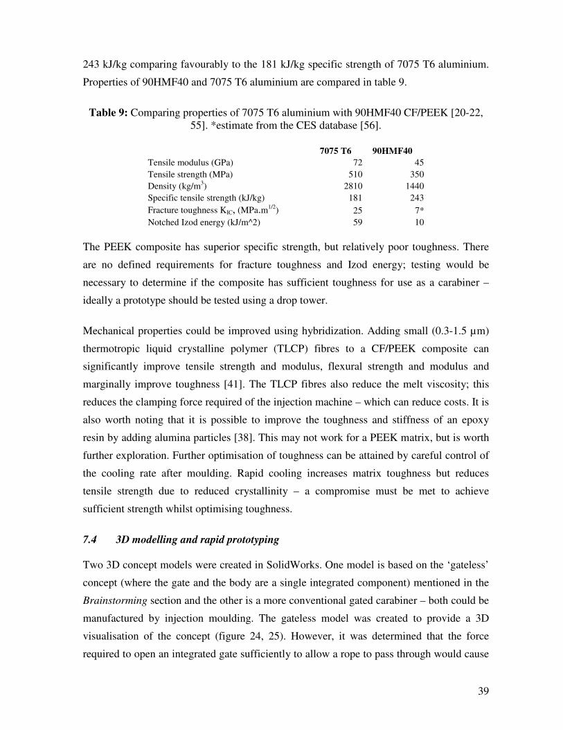
243 kJ/kg comparing favourably to the 181 kJ/kg specific strength of 7075 T6 aluminium.
Properties of 90HMF40 and 7075 T6 aluminium are compared in table 9.
Table 9: Comparing properties of 7075 T6 aluminium with 90HMF40 CF/PEEK [20-22,
55]. *estimate from the CES database [56].
7075 T6 90HMF40
Tensile modulus (GPa) 72 45
Tensile strength (MPa) 510 350
Density (kg/m3) 2810 1440
Specific tensile strength (kJ/kg) 181 243
Fracture toughness KIC, (MPa.m1/2) 25 7*
Notched Izod energy (kJ/m^2) 59 10
The PEEK composite has superior specific strength, but relatively poor toughness. There
are no defined requirements for fracture toughness and Izod energy; testing would be
necessary to determine if the composite has sufficient toughness for use as a carabiner –
ideally a prototype should be tested using a drop tower.
Mechanical properties could be improved using hybridization. Adding small (0.3-1.5 µm)
thermotropic liquid crystalline polymer (TLCP) fibres to a CF/PEEK composite can
significantly improve tensile strength and modulus, flexural strength and modulus and
marginally improve toughness [41]. The TLCP fibres also reduce the melt viscosity; this
reduces the clamping force required of the injection machine – which can reduce costs. It is
also worth noting that it is possible to improve the toughness and stiffness of an epoxy
resin by adding alumina particles [38]. This may not work for a PEEK matrix, but is worth
further exploration. Further optimisation of toughness can be attained by careful control of
the cooling rate after moulding. Rapid cooling increases matrix toughness but reduces
tensile strength due to reduced crystallinity – a compromise must be met to achieve
sufficient strength whilst optimising toughness.
7.4 3D modelling and rapid prototyping
Two 3D concept models were created in SolidWorks. One model is based on the ‘gateless’
concept (where the gate and the body are a single integrated component) mentioned in the
Brainstorming section and the other is a more conventional gated carabiner – both could be
manufactured by injection moulding. The gateless model was created to provide a 3D
visualisation of the concept (figure 24, 25). However, it was determined that the force
required to open an integrated gate sufficiently to allow a rope to pass through would cause

40
stresses very close to flexural strength of the material. Furthermore, carabiner strength is
dramatically reduced in the open gate configuration. Normally the gate would restrict the
arms of the carabiner from bending – reducing stresses due to bending in the spine.
Additionally, a small portion of the tensile load is normally transmitted through the gate. In
the gateless design the arms of the carabiner are free to bend – resulting in greater stresses
in the spine. This effect is demonstrated by the fact that most carabiners are capable of
holding a longitudinal load of 24 kN with the gate latched closed, whereas when the gate is
open the failure load decreases to around 8kN. Nonetheless, the gateless concept might be
an interesting idea to pursue for further development; a major challenge will be achieving
the transverse loading requirements.
Figure 24: A CAD model
of the gateless concept,
where the gate is integrated
into the body of the
carabiner – enabling gate
and body to be
manufactured in a single
operation.
Figure 25: A rapid
prototyped model of the
gateless concept. The CAD
model in figure 24 was
converted to STL format
and this was used to create a
rapid prototyped model by
stereo-lithography.

41
The proposed design makes use of a curved I-beam cross-section to make the most efficient
use of material whilst making sure that there are not sudden changes in cross section that
could cause stress concentrations. The gate in figure 26 is added purely to demonstrate the
gate position – it is a separate component and would not be injection moulded with the
carabiner body. The gate would be manufactured separately from high strength steel wire.
The geometry conforms to all geometrical requirements defined in the design criteria
section; however, it has not been optimised for strength and stiffness. To optimise the
Figure 26: A CAD
model of the proposed
carabiner design.
Figure 27: A rapid
prototyped model of
the proposed carabiner
design.

42
strength and stiffness, and thus minimize weight, it is necessary to carry out finite element
analysis (FEA) on the model. Some exploratory FEA was carried out on a model of an
existing carabiner to check the validity of constraints and loading conditions (see FEA and
testing section). The CAD model was prepared in such a way that the geometry and cross-
section can be modified easily, this enables iterative improvement of the design based on
feedback from FEA results. Figure 28 shows which dimensions can be modified to control
the path of the carabiner body.
Figure 29: The CAD model was prepared so that the geometry can be easily modified in
response to feedback from FEA results.
7.5 Costing
A quote for the production of the proposed design was obtained from Hilton Engineering
[57]. The quoted cost for tooling was £9620. On top of this, the cost per item would be
£3.52 for an order of 25 000 to 50 000 items in the first year. In the second year the cost per
item would be £3.34. If the cost of tooling is spread over 50 000 carabiners in the first year,
this brings the production cost per item to £3.71. Further costs would be incurred from the
additional cost of producing and attaching the wiregates – however this is likely to be small
compared to the injection moulding costs. A typical cost of an existing lightweight
carabiner is £8 [15]. This means that gate manufacture costs, advertising costs, distribution
costs and a profit margin must sum to less than £4.29 per item in order to match current
top-end carabiner prices. However, previous precedents have suggested that a premium can
43
be charged for lighter carabiners – therefore there may be potential to increase the target
selling price without much detriment to sales.
8 FEA and testing
Tensile tests were carried out on four carabiners. The aim of the testing was to determine
the failure locations and failure loads. This information could then be used to verify FEA
stress testing. In addition, the location of failure and the failure load can be used to judge
the accuracy of the assumption that a carabiner fails in pure tension.
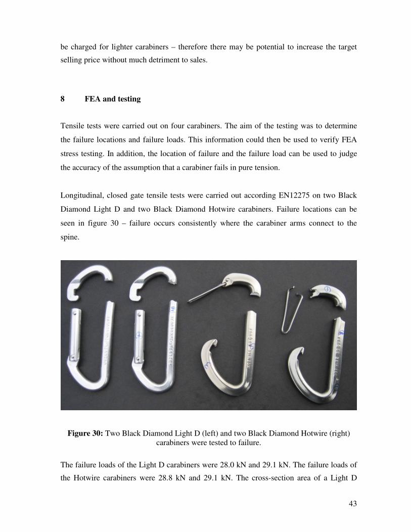
Longitudinal, closed gate tensile tests were carried out according EN12275 on two Black
Diamond Light D and two Black Diamond Hotwire carabiners. Failure locations can be
seen in figure 30 – failure occurs consistently where the carabiner arms connect to the
spine.
Figure 30: Two Black Diamond Light D (left) and two Black Diamond Hotwire (right)
carabiners were tested to failure.
The failure loads of the Light D carabiners were 28.0 kN and 29.1 kN. The failure loads of
the Hotwire carabiners were 28.8 kN and 29.1 kN. The cross-section area of a Light D

44
carabiner is 7.17 x10⁻⁵
m2 [58]. Taking an average failure load of 28.55kN, if it is assumed
that the load is taken entirely by the spine, this would result in a stress of 398 MPa in the
spine. The tensile strength of the carabiner material is around 510 MPa, so the stress in the
spine is 112 MPa higher than if the spine was in pure tension. This suggests that the
bending of the carabiner arm plays a significant role the carabiner strength.
A CAD model of a Black Diamond Light D carabiner was created in SolidWorks and FEA
stress analysis was carried out using CosmosWorks. The Light D geometry was recreated
using data from Black Diamond and overlaying an image of a Light D carabiner onto a
sketch in Solidworks.
Figure 31: Stress analysis was carried out on a model of a Black diamond Light D
carabiner using CosmosWorks.
The CAD model was meshed, material property data for aluminium 7075 T6 was entered
and forces and constraints were applied. On one end, the carabiner was constrained for
translation in three orthogonal axes to represent a fixed pin contact (see figure 31). On the
other end it was constrained in two orthogonal directions perpendicular to the spine – to
represent a moving tensile test pin. The model represented the carabiner in its open gate
configuration. A force of 7 kN was applied, in the direction of the spine, on the less
constrained of the two surfaces. A simulation was run and this resulted in maximum

45
stresses at the constraint points and stresses of a similar magnitude on the inner surface
where the arms connect to the spine. This shows some agreement with the tensile tests
performed as initial yielding occurred at the test pin contact points and then breakage
occurred at the arm/spine connecting point. However, the stress at this point was estimated
as 630 MPa. The black diamond Light D carabiner has an open gate strength rating of 7
kN, and the carabiner material has a strength of 510 MPa – this suggests that the FEA
analysis is overestimating the stress in the carabiner. Once configured correctly this
analysis could be used to optimise the carabiner design proposed in the design section.
However, this is beyond the scope of this report.
9 Future work
The next step is to comprehensively validate the finite element analysis method so that it
can be used to optimise the suggested design. Open and closed gate loading should be
analysed, in addition to transverse loading. This would require a more complex FEA model
– it would be necessary to model the gate/body assembly, taking into account the differing
material properties and the constraints at the joints. Optimisation of the geometry could
also take into account processing considerations by using injection moulding simulation
software such as Moldflow Plastic Insight (MPI). MPI could be used to optimise
processing conditions and mould design. Further study should be carried out into the
friction and wear characteristics of 90HMF40 in relation to climbing ropes.
10 Conclusions
The main aims of the project were to explore the feasibility of, and propose a design for, a
composite carabiner. The possibility of reducing the weight of a carabiner was defined as
the major motivation. A set of detailed requirements for a carabiner have been defined
based on international safety standards, geometrical criteria and environmental resistance
criteria. Material and manufacturing options have been studied and related to the carabiner
application. Low toughness was determined to be the major problem of composite
materials for lightweight carabiner design. Literature research was used to find methods of
improving composite toughness. Two design options were proposed and one of these
designs was described in detail – this made use of an injection moulded, short carbon
fibre/PEEK composite, specifically, Victrex 90HMF40. This material was noted for its

46
high specific strength, other excellent mechanical properties, and its compatibility with
injection moulding – which enables economical production. A CAD model and a rapid
prototyped model of the proposed design were created.
A carabiner made from composite materials likely to be up to 40% lighter than a
conventional aluminium carabiner. Producing a composite carabiner is likely to be more
expensive than aluminium carabiner production – particularly if hand lay-up is used.
Limited testing and finite element analysis were carried out as part of the early stages of
design optimisation. Further analysis and development is required before carabiner
production can begin.
11 Acknowledgments
The author would like to thank Bill Belcourt, Corey LaForge, Brendan Perkins and Chris
Grover of Black Diamond Equipment Ltd for generously providing technical information
on their carabiners and testing methods.
12 References
[1] Mark Twight, Extreme Alpinism: Climbing Light, Fast, and High, The Mountaineers,
1999.
[2] http://www.dmmclimbing.com/productsDetails.asp?id=1&id2=50 accessed 24
November 2007.
[3] Images from: http://www.dmmclimbing.com/products.asp?id=3&page=Products
accessed 24 November 2007.
[4] Daniel Gay and Suong V Hoa, Composite Materials: Design and Application, CRC
Press, 2006.
[5] Images from: Adrian Berry and John Arran, Trad CLIMBING +, Rockfax, 2007,
Illustrations by Ray Eckermann.
[6] EN 12275, Mountaineering equipment – Connectors – Safety requirements and test
methods, British Standards Institution, 1998.
[7] UIAA 121, Mountaineering and Climbing Equipment - Connectors, Union
Internationale des Associations d’Alpinisme, 2004.

47
[8] F. L. Matthews and R. D. Rawlings, Composite Materials: Engineering and Science,
Chapman & Hall, 1994.
[9] George H. Staab and Amos Gilat, High Strain Rate Response of Angle-Ply Glass/Epoxy
Laminates, Journal of Composite Materials, Vol. 29, No. 10, 1308-1320, 1995.
[10] Kevin Potter, An Introduction to Composite products: Design, Development and
Manufacture, Chapman & Hall, 1997.
[11] The climbing rope is threaded through the belay device, which acts as a friction brake
on the rope so that if the climber falls, his partner can halt the fall by locking off the device.
[12] A piton is a metal peg that is hammered into cracks in the rock to provide an anchor
point for a climber.
[13] http://www.bdel.com/gear/hotwire.php accessed 4 June 2008.
[14] Images from: http://www.bdel.com/gear/biners_overview.php accessed 4 June 2008.
[15] http://www.needlesports.com/acatalog/Mail_Order_Karabiners_22.html accessed 4
June 2008.
[16] http://www.rockrun.com/ accessed 4 June 2008.
[17] http://www.ahsrescue.com/c-104-making-a-carabiner-by-dmm.aspx accessed on 4
June 2008.
[18] A common knot used in rock climbing.
[19] Tom Moyer, Drop tower - A simulation of climbing belays and rescues, 2006
International Technical Rescue Symposium. Available from:
www.xmission.com/~tmoyer/testing/Simulation_of_Climbing_and_Rescue_Belays.pdf
[20] Material data sheet: Alloy 7075 plate and sheet, Alcoa Mill Products.
[21] Material data sheet: Aluminum 7075-T6; 7075-T651 from www.matweb.com
accessed 4 June 2008.
[22] http://www.onlinemetals.com/merchant.cfm?id=192&step=2&top_cat=60 accessed on
4 June 2008.
[23] B. T. Astrom, Manufacture of polymer composites, Chapman and Hall, 1997.
[24] Roylance, D., Introduction to Composite Materials, Massachusetts Institute of
Technology, 2000.
[25] CES Edupack 2007, Granta Design Limited.
[26] Guneri Akovali, Handbook of composite fabrication, Rapra Technology LTD, 2001.
[27] Serge Abrate, Impact on composite structures, Cambridge University Press, 1998.
[28] Daniel Gay and Suong V Hoa, Composite Materials: Design and Application, CRC
Press, 2006.
[29] Gao, S.-L. and J.-K. Kim, Cooling rate influences in carbon fibre/PEEK composites.
Part III: impact damage performance. Composites Part A: Applied Science and
Manufacturing, 2001. 32(6): p. 775-785.
[30] M. J. Murray, Fracture of WC-Co Alloys: An Example of Spatially Constrained Crack
Tip Opening Displacement, Proc. RSL. Ser. A, Mat. Phy. Sci., Vol. 356, No. 1687. (Sep.
26, 1977), pp. 483-508.

48
[31] http://www.itftennis.com/technical/equipment/rackets/history.asp accessed on 44 June
2008
[32] Greenhalgh, E. and M. Hiley, The assessment of novel materials and processes for the
impact tolerant design of stiffened composite aerospace structures. Composites Part A:
Applied Science and Manufacturing, 2003. 34(2): p. 151-161.
[33] Zhang, X., L. Hounslow, and M. Grassi, Improvement of low-velocity impact and
compression-after-impact performance by z-fibre pinning. Composites Science and
Technology, 2006. 66(15): p. 2785-2794.
[34] Greenhalgh, E., et al., Evaluation of toughening concepts at structural features in
CFRP--Part I: Stiffener pull-off. Composites Part A: Applied Science and Manufacturing,
2006. 37(10): p. 1521-1535.
[35] Lopez-Puente, J., The effect of low temperatures on the intermediate and high velocity
impact response of CFRPs. Composites Part B: Engineering. Composites: Part B 33
(2002) 559–566: p. 559-566.
[36] Pandita, S.D., Impact properties of weft knitted fabric reinforced composites. p. 1113-
1123.
[37] Cartie, D.D.R., Effect of resin and fibre properties on impact and compression after
impact performance of CFRP. p. 483-493.
[38] Found, M.S., et al., Comparison of damage resistance of CFRP lightweight panels.
Composites Part A: Applied Science and Manufacturing, 2005. 36(2): p. 197-203.
[39] Wetzel, B., Epoxy nanocomposites with high mechanical and tribological
performance. p. 2055-2067.
[40] Wang, X., et al., Low velocity impact properties of 3D woven basalt/aramid hybrid
composites. Composites Science and Technology. In Press, Corrected Proof.
[41] He, J., In situ hybrid composites of thermoplastic poly(ether ether ketone), poly(ether
sulfone) and polycarbonate. p. 1919-1930.
[42] Bagwell, R. and R. Wetherhold, Fiber pullout behavior and impact toughness of short
shaped copper fibers in thermoset matrices. Composites Part A: Applied Science and
Manufacturing, 2005. 36(5): p. 683-690.
[43] Sohn, M.S., Impact damage characterisation of carbon fibre/epoxy composites with
multi-layer reinforcement. 2000: p. 681-691.
[44] Walker, L., Improving impact resistance of carbon-fibre composites through
interlaminar reinforcement. p. 893-902.
[45] Thomason, J.L., The influence of fibre length and concentration on the properties of
glass fibre reinforced polypropylene: 7. Interface strength and fibre strain in injection
moulded long fibre PP at high fibre content. Composites Part A: Applied Science and
Manufacturing, 2007. 38(1): p. 210-216.
[46] Gao, S.L., Cooling rate influences in carbon fibre/PEEK composites. Part 1.
Crystallinity and interface adhesion. p. 517-530.
49
[47] Gao, S.-L. and J.-K. Kim, Cooling rate influences in carbon fibre/PEEK composites.
Part II: interlaminar fracture toughness. Composites Part A: Applied Science and
Manufacturing, 2001. 32(6): p. 763-774.
[48] Gao, S.-L. and J.-K. Kim, Cooling rate influences in carbon fibre/PEEK composites.
Part III: impact damage performance. Composites Part A: Applied Science and
Manufacturing, 2001. 32(6): p. 775-785.
[49] Pegoretti, A., A. Zanolli, and C. Migliaresi, Flexural and interlaminar mechanical
properties of unidirectional liquid crystalline single-polymer composites. Composites
Science and Technology, 2006. 66(13): p. 1953-1962.
[50] Tanoglu, M., et al., The effects of glass-fiber sizings on the strength and energy
absorption of the fiber/matrix interphase under high loading rates. Composites Science
and Technology, 2001. 61(2): p. 205-220.
[51] Data from CES Edupack, name of database record: Cyanate ester/HM carbon fibre,
UD composite, Quasi-isotropic Laminate.
[52] Tom Kelley, The art of Innovation, Profile Books, 2001.
[53] Image from: http://www.madehow.com/Volume-3/Tennis-Racket.html accessed 4
June 2008.
[54] CES Edupack 2007; name of database record: PEEK/IM carbon fibre UD composite,
quasi-isotropic laminate.
[55] T. A Siewert et al, Performance Verification of Impact Machines
for Testing Plastics, J. Res. Natl. Inst. Stand. Technol. 104, 557 (1999).
[56] CES Edupack 2007; name of database record: PEEK 30% carbon fibre.
[57] www.hilton-engineering.co.uk
[58] Information supplied by Black Diamond directly.