design manufacturing selection process - nasa · 2013-08-30 · n93-30865 process and assembly...
TRANSCRIPT
N93-30865
Process and Assembly Plans for Low Cost
Commercial Fuselage Structure
Kurtis Willden, Stephen Metschan, Val Starkey
Boeing Commercial Airplanes
Design / Manufacturing Selection Process
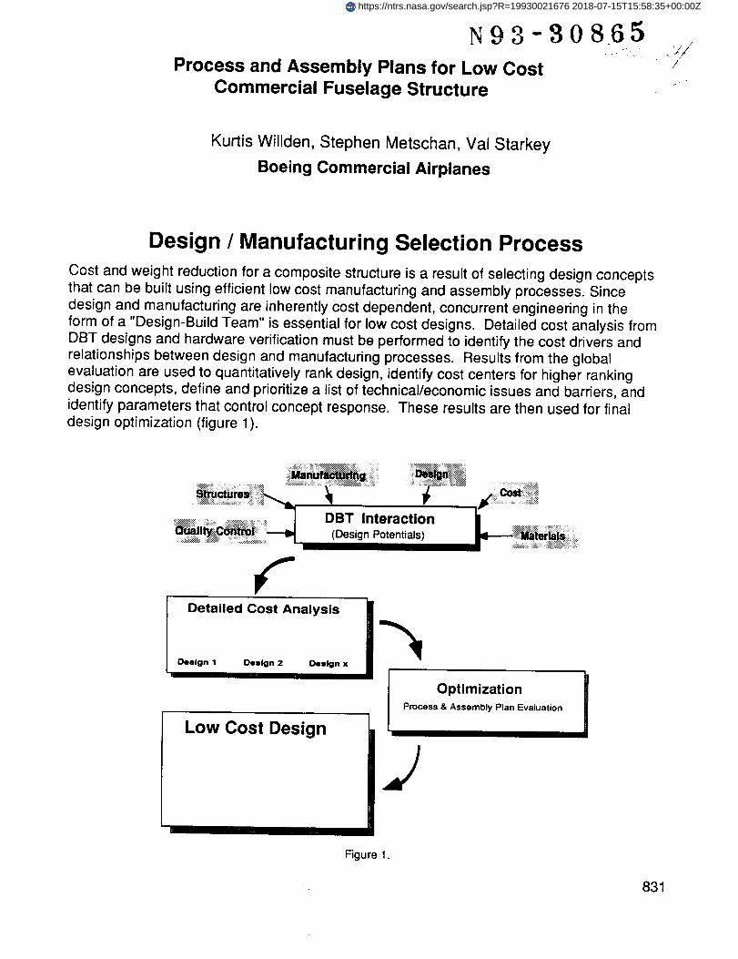
Cost and weight reduction for a composite structure is a result of selecting design conceptsthat can be built using efficient low cost manufacturing and assembly processes. Since
design and manufacturing are inherently cost dependent, concurrent engineering in theform of a "Design-Build Team" is essential for low cost designs. Detailed cost analysis fromDBT designs and hardware verification must be performed to identify the cost drivers andrelationships between design and manufacturing processes. Results from the globalevaluation are used to quantitatively rank design, identify cost centers for higher rankingdesign concepts, define and prioritize a list of technical/economic issues and barriers, andidentify parameters that control concept response. These results are then used for finaldesign optimization (figure 1).
Detailed Cost Analysis i
OptimizationProcess & Assembly Plan Evaluation
J
Figure 1.
831
https://ntrs.nasa.gov/search.jsp?R=19930021676 2018-07-15T15:58:35+00:00Z
Parameter Evaluation
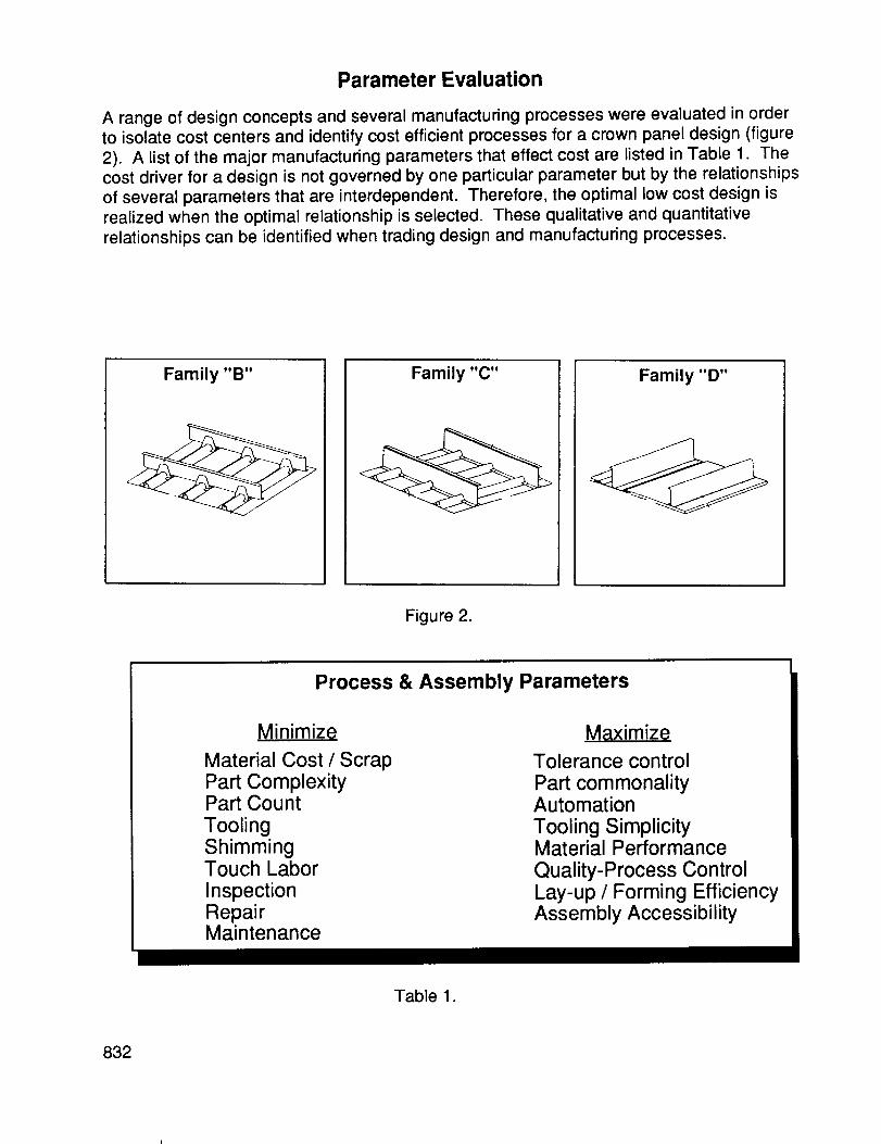
A range of design concepts and several manufacturing processes were evaluated in orderto isolate cost centers and identify cost efficient processes for a crown panel design (figure
2). A list of the major manufacturing parameters that effect cost are listed in Table 1. Thecost driver for a design is not governed by one particular parameter but by the relationshipsof several parameters that are interdependent. Therefore, the optimal low cost design isrealized when the optimal relationship is selected. These qualitative and quantitativerelationships can be identified when trading design and manufacturing processes.
Family "B" Family "C" Family "D"
Figure 2.
Process & Assembly Parameters
Minimize
Material Cost / ScrapPart ComplexityPart CountToolingShimmingTouch LaborInspectionRepairMaintenance
Maximize
Tolerance controlPart commonalityAutomationTooling SimplicityMaterial PerformanceQuality-Process ControlLay-up / Forming EfficiencyAssembly Accessibility
Table 1.
832
Crown Panel Global OptimizationProcess & Assembly Selection
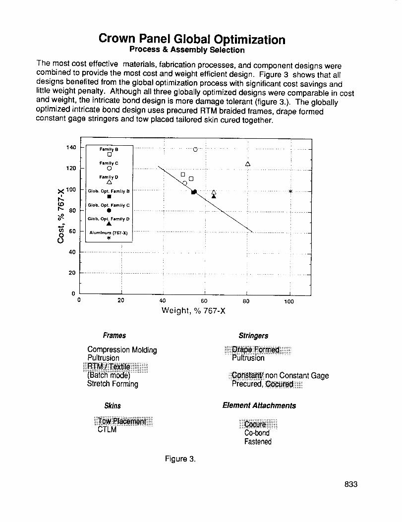
The most cost effective materials, fabrication processes, and component designs werecombined to provide the most cost and weight efficient design. Figure 3 shows that alldesigns benefited from the global optimization process with significant cost savings andlittle weight penalty. Although all three globally optimized designs were comparable in costand weight, the intricate bond design is more damage tolerant (figure 3.). The globallyoptimized intricate bond design uses precured RTM braided frames, drape formedconstant gage stringers and tow placed tailored skin cured together.
140
120
X 100
_ 80
.,.rm 60O
4O
2O
Fmmlly B[]
Family CO
Fam_y D
GIob. Opt. Family B
Glob. Opt. Family C
Glob. OpXFamlly D
Aluminum (767-X)
i
iii iiili i
1 i i i0 20 40 60 80 100
Weight, % 767-X
Frames
Compression MoldingPultrusion
Stretch Forming
Stringers
......Puitrusion .....................
iiii_ot_s'_i!non Constant GagePrecured, C_tediiiii_iiiiiill
Skins
CTLM
Figure 3.
Element Attachments
iiiii!i! iiiiiii!iiii!iiiiiiiiiCo-bondFastened
833

Crown Panel Skin Fabrication
The ability to accurately and efficiently fabricate tailored skins on contoured surfaces with
various forms of materials, makes the tow placement process ideal for crown panel
fabrication (figure 4). Additional advantages are realized when considering batch modefabrication of several crown panels on one mandrel. The same work station can also
produce side and keel panels or a full barrel fuselage section. The pay-out rate for a single
head ranges between 10-50 Ibs./hr. depending on design requirements. Although the towplacement head has been demonstrated for a single head dispenser, additional heads that
are single or multiple task oriented may be implemented. The use of multiple robot enddefectors within the same work station can perform additional operations such as trimming
and in-line inspection. These types of improvements could increase skin fabrication by
100% if the cost of increased efficiency is justified.
Tow Placement Work Station
ATCAS .>
TOW PLACEMENT CELL ._q[!i.,_ i_ SIDEsK, _'NDN_ ¢00L
TOW PLACEMENT ROBOTS /_ _.-S Hb<.j-L.'-:-
• " YU
_.1_-1 ! _._ .---- .-_;.,"o17,,_-"-....... "-. z-- :---<-_ ,,'
" AND ./ J _ " "" _\ /_ _f_• CURE TOOL -> ....... -J"_,, j/" , _:_'o*; ¢'
CROWN SKIN WINDING TOOL -- "_ ":_--_,{ ,,,,,,_:'_-_
o Full Barrel Capabilitieso Efficient Ply add/dropo Cut and Trim Capabilitieso Ply Thickness Control
o Hybrid Material Handlingo Scrape rate 5-20%o Single Head rate -50 Ibs./hr.o Temperature Conditioning
Figure 4
834
Crown Panel Frame Fabrication
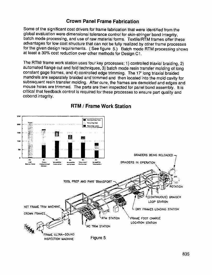
Some of the significant cost drivers for frame fabrication that were identified from the
global evaluation were dimensional tolerance control for skin-stringer bond integrity,batch mode processing, and use of raw material forms. Textile/RTM frames offer these
advantages for low cost structure that can not be fully realized by other frame processesfor the given design requirements. ( See figure 5.) Batch mode RTM processing showsat least a 30% cost reduction over other methods for Design C1.
The RTM/frame work station uses four key processes; 1) controlled triaxial braiding, 2)automated flange cut and fold techniques, 3) batch mode resin transfer molding of longconstant gage frames, and 4) controlled edge trimming. The 17' long triaxial braidedmandrels are separately braided and trimmed and then located into the mold cavity forsubsequent resin transfer molding. After cure, the frames are demolded and edges andmouse holes are trimmed. The parts are then inspected for panel bond assembly. It iscritical that feedback control is required for these processes to ensure part quality andcobond integrity.
RTM / Frame Work Station
25O
2OO
150
:i:!_:¸ ii
!!_!!_!!i¸ ,,,
'i!!!...... m.....u ,,,,......'_ ijii,._ .............. ........ _.:_m....
SO0 _i:i: :::::_ ::::g,__:4
BRAIDERS BEING RELOADED7BRAIDERS IN OPERATION i
10u_llh wo.m ¢emp_*_lee,- _-*l*o.em* 0-*14.|_ Pla_ *_ _o.*_-uom*
"-" \ F
TOOL PREP AND PART TRANSPORT _ J _._ "_-"-) _,"_._._ _'_'H ..... "
._ • " _ LOOP STATIONNET FRAME TRIM MACHINE "_ DRY FRAMES LOADING STATION
LOCATION STATION
_C TRIM STATION
_F'RAME ULTRA-SOUND
INSPECTION MACHINE Figure 5
835
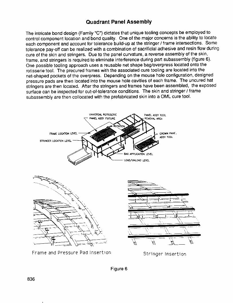
Quadrant Panel Assembly
The intricate bond design (Family "C") dictates that unique tooling concepts be employed to
control component location and bond quality. One of the major concerns is the ability to locate
each component and account for tolerance build-up at the stringer / frame intersections. Some
tolerance pay-off can be realized with a combination of sacrificial adhesive and resin flow during
cure of the skin and stringers. Due to the panel curvature, a reverse assembly of the skin,
frame, and stringers is required to eliminate interference during part subassembly (figure 6).
One possible tooling approach uses a reusable net shape bag/overpress located onto therotisserie tool. The precured frames with the associated cure tooling are located into the
net-shaped pockets of the overpress. Depending on the mouse hole configuration, designed
pressure pads are then located into the mouse hole cavities of each frame. The uncured hat
stringers are then located. After the stringers and frames have been assembled, the exposed
surface can be inspected for out-of-tolerance conditions. The skin and stringer / frame
subassembly are then collocated with the prefabricated skin into a OML cure tool.
UNIVERSAL ROTISSERIE
PANEL ASSY
FRAME LOCATION
STRINGER LOCATION
BAG APPUCATION LEVEL
LOAD/UNLOAD LEVEL
PANEL ASSY TOOL
REMOVAL AREA
CROWN PANEL
ASSY TOOL
Frame and Pressure Pad Insertion Stringer Insertion
Figure 6
836
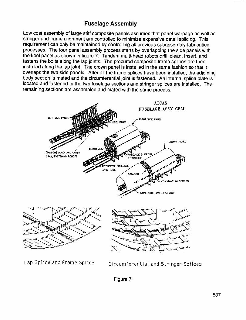
Fuselage Assembly
Low cost assembly of large stiff composite panels assumes that panel warpage as well asstringer and frame alignment are controlled to minimize expensive detail splicing. Thisrequirement can only be maintained by controlling all previous subassembly fabricationprocesses. The four panel assembly process starts by overlapping the side panels withthe keel panel as shown in figure 7. Tandem multi-head robots drill, clean, insert, andfastens the bolts along the lap joints. The precured composite frame splices are theninstalled along the lap joint. The crown panel is installed in the same fashion so that it
overlaps the two side panels. After all the frame splices have been installed, the adjoiningbody section is mated and the circumferential joint is fastened. An internal splice plate islocated and fastened to the two fuselage sections and stringer splices are installed. Theremaining sections are assembled and mated with the same process.
ATCAS
FUSELAGE ASS¥ CELL
LEFT SIDE RIGHT SIDE PANELPANEL
('TANDEM) INNER AND OUTER PPORT CROWN PANEL
DRILL/FASI'ENING ROBOTS _EESU
ON
Lap Splice and Frame Splice Circumferential and Stringer Splices
Figure 7
837
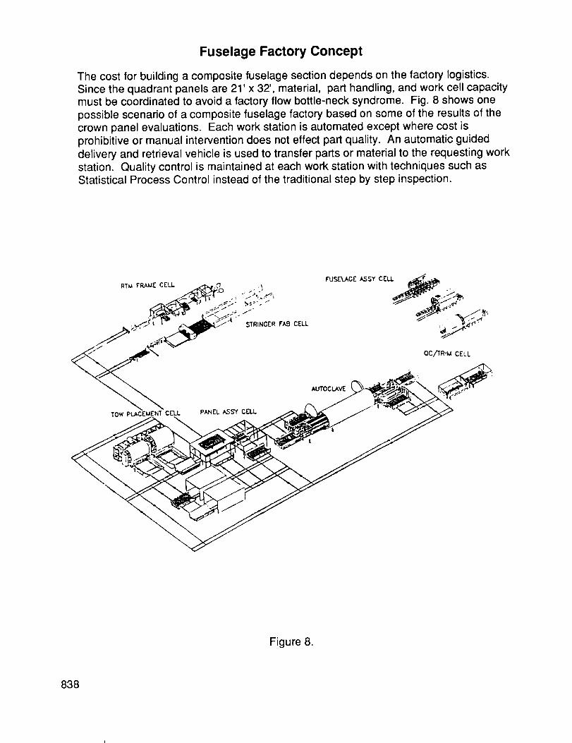
Fuselage Factory Concept
The cost for building a composite fuselage section depends on the factory logistics.
Since the quadrant panels are 21' x 32 °, material, part handling, and work cell capacitymust be coordinated to avoid a factory flow bottle-neck syndrome. Fig. 8 shows one
possible scenario of a composite fuselage factory based on some of the results of the
crown panel evaluations. Each work station is automated except where cost is
prohibitive or manual intervention does not effect part quality. An automatic guided
delivery and retrieval vehicle is used to transfer parts or material to the requesting work
station. Quality control is maintained at each work station with techniques such asStatistical Process Control instead of the traditional step by step inspection.
Figure 8.
838

Program Status
Several tests and hardware coupons are or have been completed to understand the
cost impact of material/structural performance and manufacturing processes for low
cost structure. (See figure 9.) Low cost damage tolerant materials and processibility of
these materials are under investigation and will be demonstrated in support of the near
term local optimization for the crown panel and future activities with the keel and sidepanels. Panel warpage and part tolerance control will be demonstrated with innovative
tooling, fastening, and splice details.
TO Date 0 Tow placed flat hybrid panels(AS4 / S-2, AS4 / T-1000)
o Tow placed tailored hat and blade panels(combinations of 977-2, 938, AS4, IM6, RC 35%,44%)
o Thermoplastic fastener trials
o Tooling trials for blades, hats, and intricate bond
Near Term o Large Intricate bond demonstration panels(Tooling Development 8'x9')
o RTM-braided frames (3'-10')
o Panel warpage / assembly evaluations
o Innovative design splices
Figure 9.
839
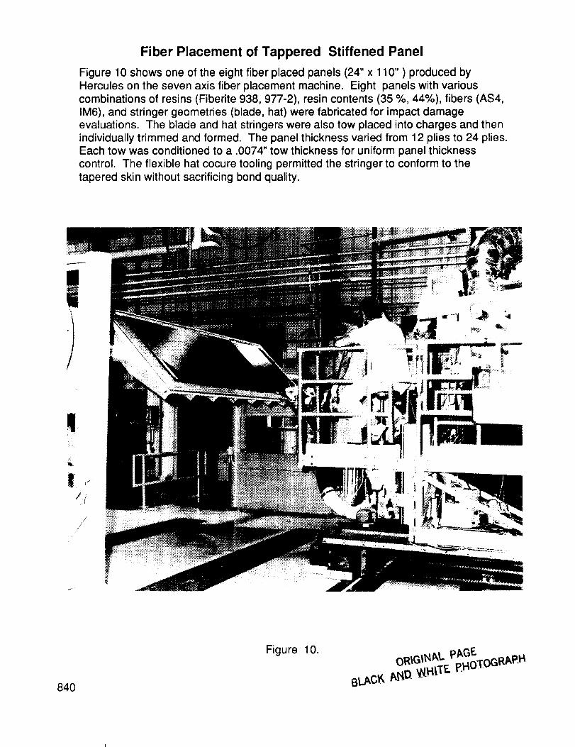
Fiber Placement of Tappered Stiffened Panel
Figure 10 shows one of the eight fiber placed panels (24" x 110" ) produced by
Hercules on the seven axis fiber placement machine. Eight panels with various
combinations of resins (Fiberite 938, 977-2), resin contents (35 %, 44%), fibers (AS4,
IM6), and stringer geometries (blade, hat) were fabricated for impact damage
evaluations. The blade and hat stringers were also tow placed into charges and thenindividually trimmed and formed. The panel thickness varied from 12 plies to 24 plies.
Each tow was conditioned to a .0074" tow thickness for uniform panel thickness
control. The flexible hat cocure tooling permitted the stringer to conform to the
tapered skin without sacrificing bond quality.
!
/r/
//
/
//
840
Figure 10.oRIGINAt, pAGE
BLACK A_D _H_TF- p+HoT[OGRAP-H
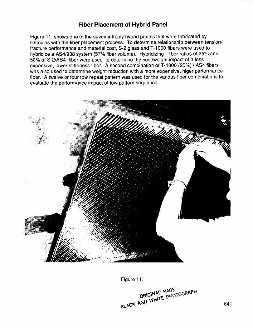
Fiber Placement of Hybrid Panel
Figure 11. shows one of the seven intraply hybrid panels that were fabricated by
Hercules with the fiber placement process. To determine relationship between tension/fracture performance and material cost, S-2 glass and T-1000 fibers were used to
hybridize a AS4/938 system (57% fiber volume)• Hybridizing - fiber ratios of 25% and
50% of S-2/AS4 fiber were used to determine the cost/weight impact of a less
expensive, lower stiffeness fiber. A second combination of T-1000 (25%) / AS4 fibers
was also used to determine weight reduction with a more expensive, higer performance
fiber. A twelve or four tow repeat pattern was used for the various fiber combinations to
evaluate the performance impact of tow pattern sequence.
Figure 11.
841
BIOGRAPHY
Kurtis S. Willden, ATCAS Manufacturing Lead Engineer
Boeing Commercial Airplanes
Graduated from Brigham Young University with a Bachelor and Masters
degree in Mechanical Engineering. Experience includes advanced research
and development of manufactured composite structures with General
Dynamics and Boeing.
842