design & manufacturing demands in laser automotive prototyping/media/files/autosteel/great...
TRANSCRIPT
w w w . a u t o s t e e l . o r g
Design & Manufacturing
Demands in
Laser Automotive Prototyping
Gordon McIntosh President, SWS-Trimac
w w w . a u t o s t e e l . o r g
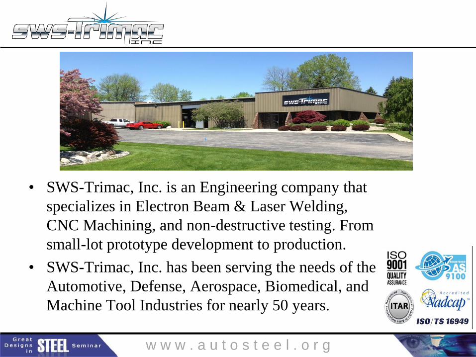
• SWS-Trimac, Inc. is an Engineering company that
specializes in Electron Beam & Laser Welding,
CNC Machining, and non-destructive testing. From
small-lot prototype development to production.
• SWS-Trimac, Inc. has been serving the needs of the
Automotive, Defense, Aerospace, Biomedical, and
Machine Tool Industries for nearly 50 years.
w w w . a u t o s t e e l . o r g
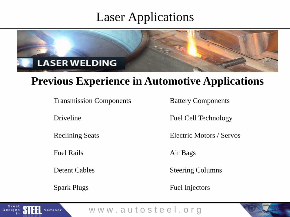
Laser Applications
Previous Experience in Automotive Applications
Transmission Components Battery Components
Driveline Fuel Cell Technology
Reclining Seats Electric Motors / Servos
Fuel Rails Air Bags
Detent Cables Steering Columns
Spark Plugs Fuel Injectors
w w w . a u t o s t e e l . o r g
Laser Welding Environments
• Welding Environments
– Safe
– Versatile
– Efficient
– Repeatable
– Work Stations May Vary Greatly
– Manual, CNC Tables/Gantry, Robots, Etc.
w w w . a u t o s t e e l . o r g
Laser Welding Recommended Practices
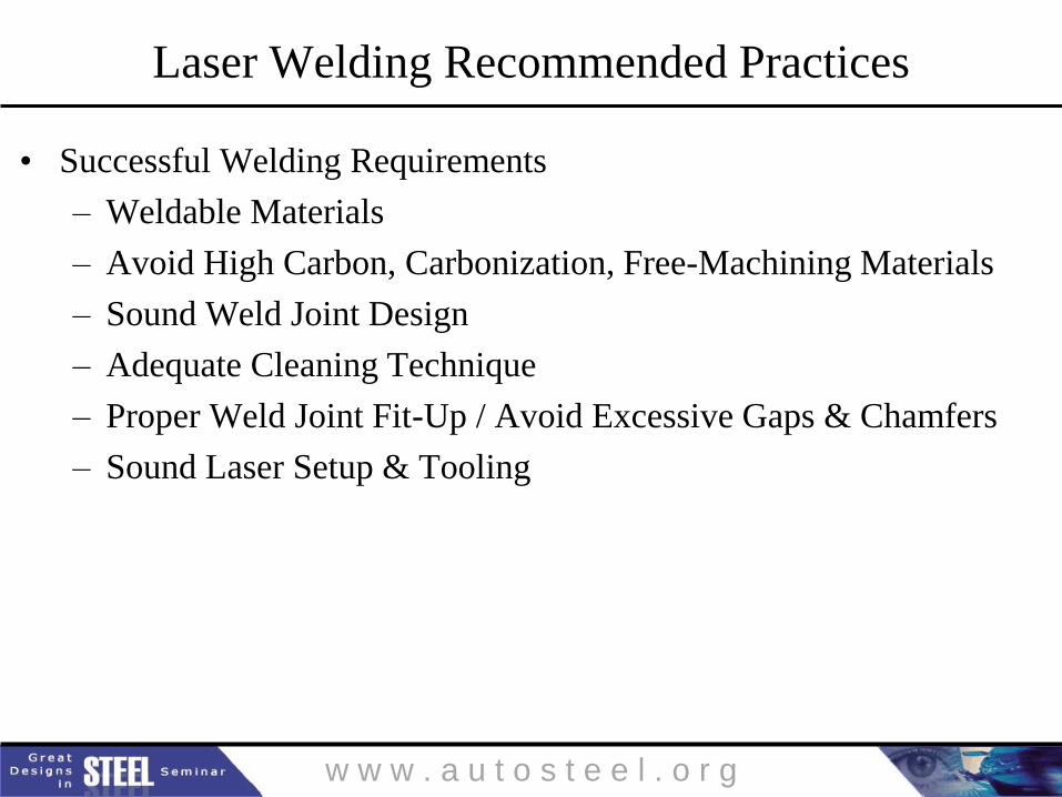
• Successful Welding Requirements
– Weldable Materials
– Avoid High Carbon, Carbonization, Free-Machining Materials
– Sound Weld Joint Design
– Adequate Cleaning Technique
– Proper Weld Joint Fit-Up / Avoid Excessive Gaps & Chamfers
– Sound Laser Setup & Tooling
w w w . a u t o s t e e l . o r g
Material Selection
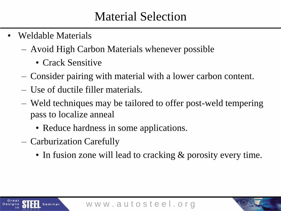
• Weldable Materials
– Avoid High Carbon Materials whenever possible
• Crack Sensitive
– Consider pairing with material with a lower carbon content.
– Use of ductile filler materials.
– Weld techniques may be tailored to offer post-weld tempering
pass to localize anneal
• Reduce hardness in some applications.
– Carburization Carefully
• In fusion zone will lead to cracking & porosity every time.
w w w . a u t o s t e e l . o r g
Material Selection
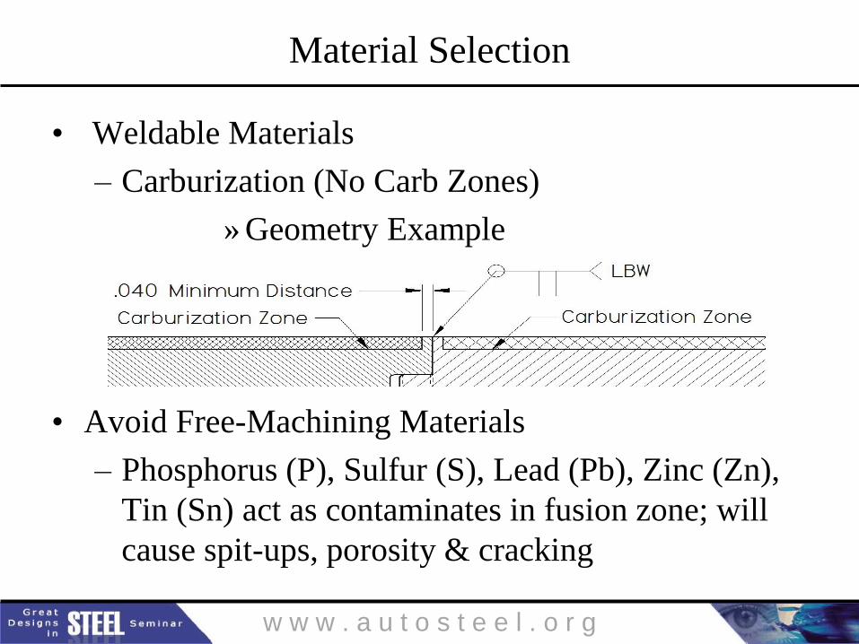
• Weldable Materials
– Carburization (No Carb Zones)
» Geometry Example
• Avoid Free-Machining Materials
– Phosphorus (P), Sulfur (S), Lead (Pb), Zinc (Zn),
Tin (Sn) act as contaminates in fusion zone; will
cause spit-ups, porosity & cracking
w w w . a u t o s t e e l . o r g
Weld Joint Selection
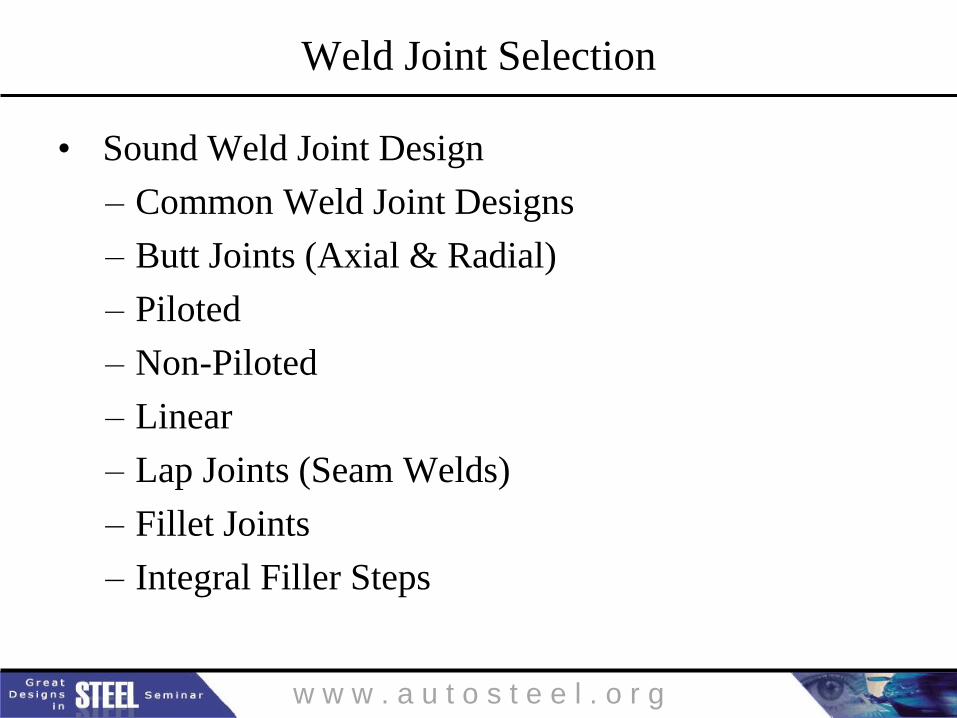
• Sound Weld Joint Design
– Common Weld Joint Designs
– Butt Joints (Axial & Radial)
– Piloted
– Non-Piloted
– Linear
– Lap Joints (Seam Welds)
– Fillet Joints
– Integral Filler Steps
w w w . a u t o s t e e l . o r g
Weld Joint Selection
• Butt Joints
– Most Common
– Piloted joints are preferred as they minimize post-
weld distortion and need for elaborate weld
tooling.
– Applications with crack sensitive materials or high
demand for post weld tolerance should consider an
interference fit.
– Tight fitting joints (Compression) reduce the post-
weld tensile stress due to the inherent shrink across
the weld joint.
w w w . a u t o s t e e l . o r g
Weld Joint Selection
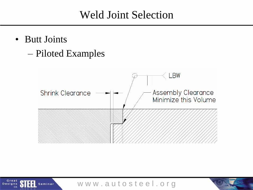
• Butt Joints
– Piloted Examples
w w w . a u t o s t e e l . o r g
Weld Joint Selection
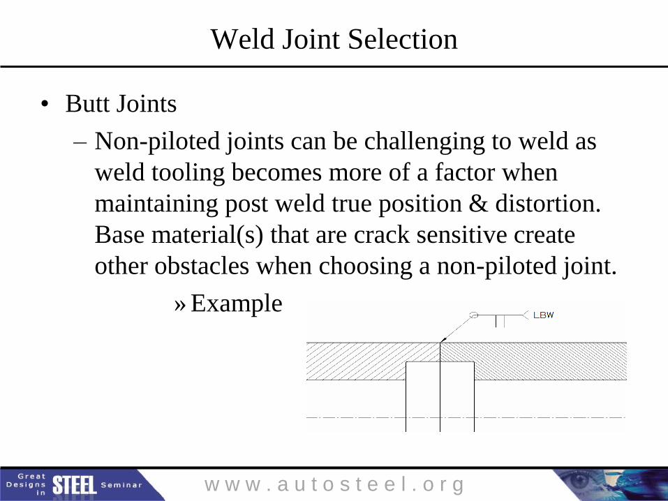
• Butt Joints
– Non-piloted joints can be challenging to weld as
weld tooling becomes more of a factor when
maintaining post weld true position & distortion.
Base material(s) that are crack sensitive create
other obstacles when choosing a non-piloted joint.
» Example
w w w . a u t o s t e e l . o r g
Weld Joint Selection
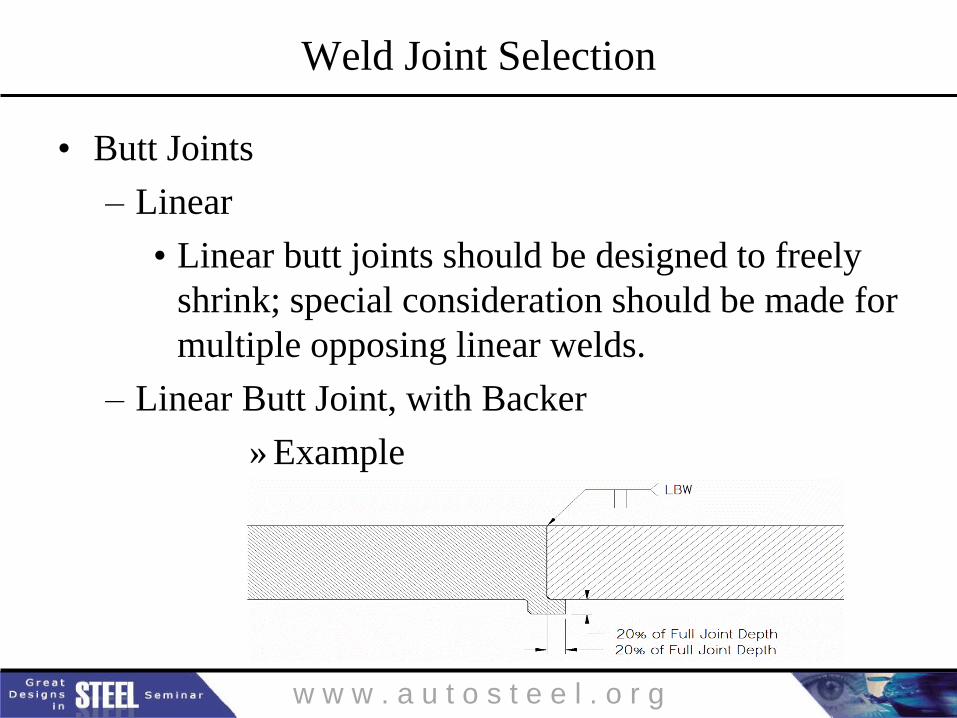
• Butt Joints
– Linear
• Linear butt joints should be designed to freely
shrink; special consideration should be made for
multiple opposing linear welds.
– Linear Butt Joint, with Backer
» Example
w w w . a u t o s t e e l . o r g
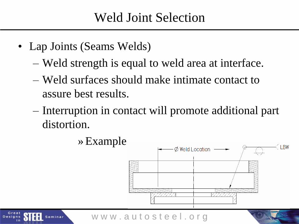
Weld Joint Selection
• Lap Joints (Seams Welds)
– Weld strength is equal to weld area at interface.
– Weld surfaces should make intimate contact to
assure best results.
– Interruption in contact will promote additional part
distortion.
» Example
w w w . a u t o s t e e l . o r g
Weld Joint Selection
• Fillet Joints
– Commonly done although Crack sensitive
materials can be especially tricky.
– Many Laser applications are done without the use
of filler material.
– In some cases, filler material may be added via
wire feed, filler shim, or filler wire added manually
in separate operation.
w w w . a u t o s t e e l . o r g
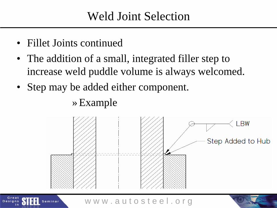
Weld Joint Selection
• Fillet Joints continued
• The addition of a small, integrated filler step to
increase weld puddle volume is always welcomed.
• Step may be added either component.
» Example
w w w . a u t o s t e e l . o r g
Laser Weld Preparation
Adequate Cleaning Technique
– All weld joint surfaces should be thoroughly
cleaned prior to weld.
– What needs to be cleaned?
– Cleaning Techniques
– Quality Control
w w w . a u t o s t e e l . o r g
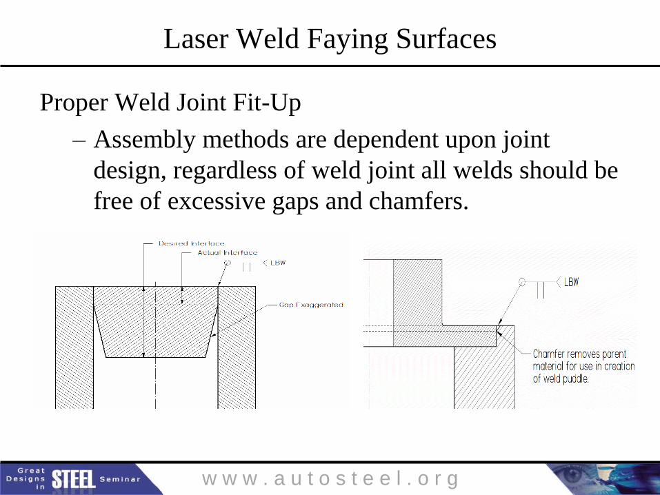
Laser Weld Faying Surfaces
Proper Weld Joint Fit-Up
– Assembly methods are dependent upon joint
design, regardless of weld joint all welds should be
free of excessive gaps and chamfers.
w w w . a u t o s t e e l . o r g
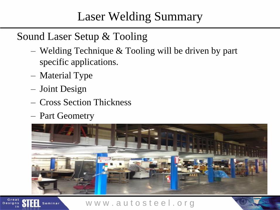
Laser Welding Summary
Sound Laser Setup & Tooling
– Welding Technique & Tooling will be driven by part
specific applications.
– Material Type
– Joint Design
– Cross Section Thickness
– Part Geometry
w w w . a u t o s t e e l . o r g
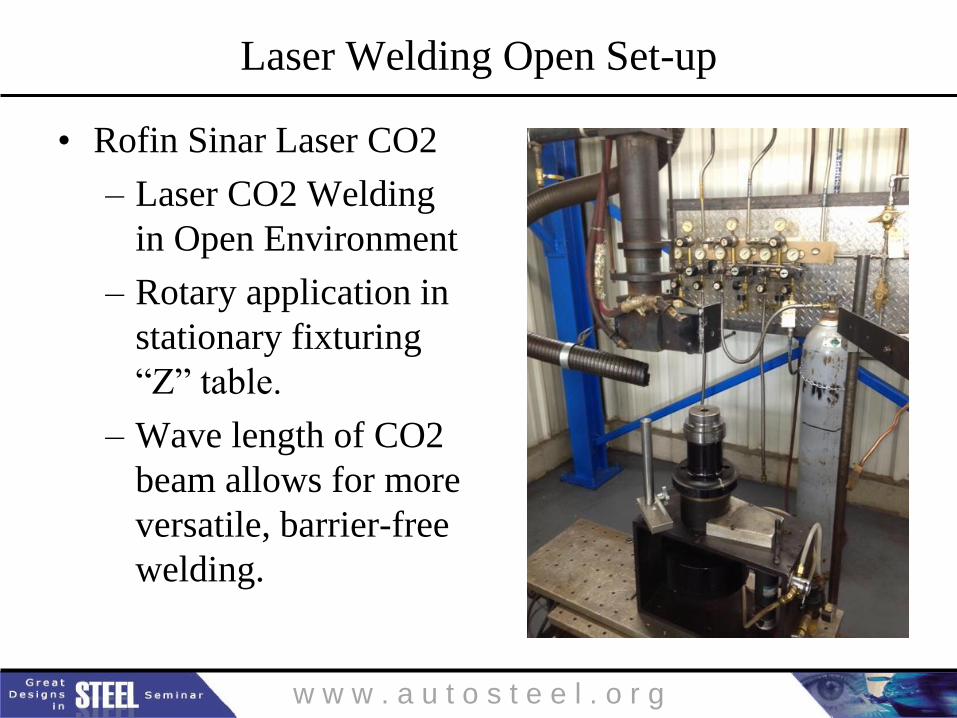
Laser Welding Open Set-up
• Rofin Sinar Laser CO2
– Laser CO2 Welding
in Open Environment
– Rotary application in
stationary fixturing
“Z” table.
– Wave length of CO2
beam allows for more
versatile, barrier-free
welding.
w w w . a u t o s t e e l . o r g
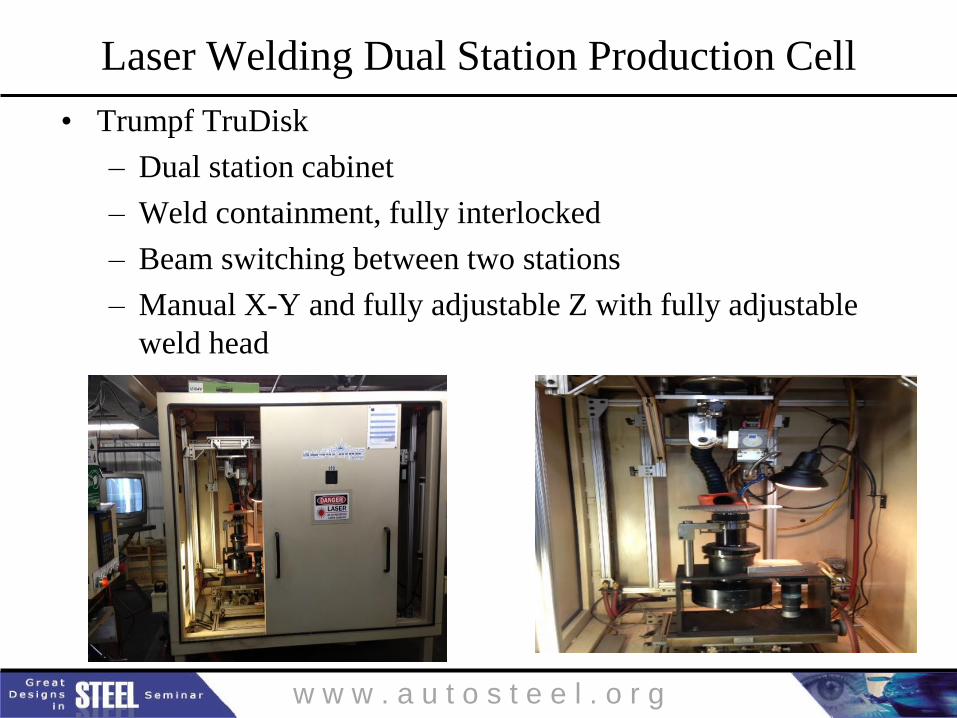
Laser Welding Dual Station Production Cell
• Trumpf TruDisk
– Dual station cabinet
– Weld containment, fully interlocked
– Beam switching between two stations
– Manual X-Y and fully adjustable Z with fully adjustable
weld head
w w w . a u t o s t e e l . o r g
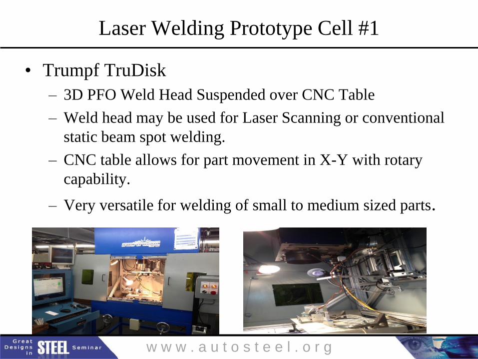
Laser Welding Prototype Cell #1
• Trumpf TruDisk
– 3D PFO Weld Head Suspended over CNC Table
– Weld head may be used for Laser Scanning or conventional
static beam spot welding.
– CNC table allows for part movement in X-Y with rotary
capability.
– Very versatile for welding of small to medium sized parts.
w w w . a u t o s t e e l . o r g
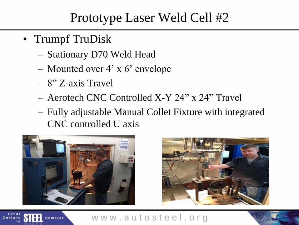
Prototype Laser Weld Cell #2
• Trumpf TruDisk
– Stationary D70 Weld Head
– Mounted over 4’ x 6’ envelope
– 8” Z-axis Travel
– Aerotech CNC Controlled X-Y 24” x 24” Travel
– Fully adjustable Manual Collet Fixture with integrated
CNC controlled U axis
w w w . a u t o s t e e l . o r g
Thank You!
– Question & Answer
w w w . a u t o s t e e l . o r g
Great Designs in Steel is Sponsored by:
Use your web-enabled device to download the presentations from today’s event
PRESENTATIONS WILL BE AVAILABLE MAY 16