design manual small bridges
TRANSCRIPT

Transport Research Laboratory Department for International DevelopmentOld Wokingham Road 94 Victoria StreetCrowthorne, Berkshire, RG45 6AU London, SW1E 5JH
Overseas Road Note 9
A design manual for small bridges
ORN 9

First Published 1992Second edition 2000ISSN 0951-8797Copyright Transport Research Laboratory 2000.
This document is an output from a project funded by the UKDepartment for International Development DFID for the benefitof developing countries. The views expressed are not necessarilythose of the DFID.
TRL is committed to optimising energy efficiency, reducingwaste and promoting recycling and re-use. In support of theseenvironmental goals, this report has been printed on recycledpaper, comprising 100% post-consumer waste, manufacturedusing a TCF (totally chlorine free) process.
The Transport Research Laboratory and TRL are trading names of TRL Limited,a member of the Transport Research Foundation Group of CompaniesTRL Limited. Registered in England, Number 3142272Registered Offices: Old Wokingham Road, Crowthorne, Berkshire, RG45 6AU.
ii

ACKNOWLEDGEMENTS
The first edition was compiled by J D Parry of the Overseas Unit at TRL (Head of Unit Mr J S Yerrell) withassistance from the late Mr D M Brooks, Dr T E Jones and Mr N C Hewitt.
It is based on a draft commissioned from Rendel Palmer and Tritton, Consulting Engineers of London. Thenumerous other sources are listed in the references. Mr P K Thomas provided an earlier text; Mr H Lewis assistedin the editing of the final version. Contributions were also made by Central Units and Bridges Division at TRL.
We also acknowledge the generous help given by the following people who kindly reviewed the pre-publicationdraft and offered constructive comments and additions.
Mr R C Petts, Intech Associates, UKMr P Wootton, Civil Planning Partnership, ZimbabweMr G A Taylor, Ministry of Public Works, KenyaMajor J F MacKenzie, R EDr R J Freer-Hewish, University of Birmingham.
This manual is published by the Transport Research Laboratory as part of the programme of the Department forinternational Development (DFID).
The second edition introduces a separate chapter on masonry as a bridge building material. This chapter is based ona draft by Mr A Beusch of Intech Associates, with further contributions from Mr J D Parry, Mr N C Hewitt and DrA F Daly of TRL.
OVERSEAS ROAD NOTES
Overseas Road Notes are prepared principally for road and transport authorities in countries receiving technicalassistance from the British Government. A limited number of copies is available to other organisations and toindividuals with an interest in roads overseas, and may be obtained from:
International DivisionTransport Research LaboratoryCrowthorne, Berkshire, RG45 6AUUnited Kingdom
Limited extracts from the text may be reproduced provided the source is acknowledged. For more extensivereproduction, please write to the address given above.
iii

iv

CONTENTS
Page
1. INTRODUCTION 1
2. PLANNING 3
3. SITE INVESTIGATIONS 13
4. RIVER HYDRAULICS 23
5. HYDRAULIC DESIGN 33
6. RIVER AND SCOUR PROTECTION 43
7. LOW LEVEL WATER CROSSING 55
8. SUBSTRUCTURES AND FOUNDATIONS 65
9. CONCRETE SUPERSTRUCTURES 115
10. STEEL/CONCRETE COMPOSITE SUPERSTRUCTURES 137
11. TIMBER SUPERSTRUCTURES 155
12. CULVERTS 165
13. EMERGENCY AND TEMPORARY STRUCTURES 193
14. BRIDGE BUILDING MATERIALS 201
15. MASONRY 215
16. DRAWINGS AND SPECIFICATIONS 225
INDEX 229
V

vi
1 Introduction
This manual offers highway engineers a comprehensiveset of guidelines to assist and simplify the process ofdesigning small bridges and culverts. These structuresare an essential part of every road network. They are farmore common than large bridges and are simpler todesign and construct. For the purposes of the manual,'small bridges' are defined as single or multispanstructures with individual spans no more than 12m long,ie taking one span to bridge a two-lane highway withshoulders or two spans to bridge a dual carriageway.
The guidelines cover the entire design process, from theplanning stage through site investigations and materialsanalysis, hydraulic design and structural design, to thefinal preparation of drawings and detailed specifications.There are many textbooks and other technicalpublications that provide excellent treatments of all theseaspects of bridge design: some are listed in the manual asuseful reference material for readers wishing to pursuesubjects in more detail. These sources, however, are allintended for bridge engineers or students of bridgeengineering. The present manual is meant to be of use ina bridge design office, but it is aimed also at the generalcivil engineer who is not a bridge specialist but who maynonetheless be required occasionally to construct a roadthat crosses a river or other obstruction. He/she may be aprovincial roads engineer, extending a regional networkof feeder roads with permanent bridges, an armyengineer or an engineer involved in famine reliefdistribution, needing rapid but temporary solutions tobridging problems
Because these non-specialist bridge builders have otherprofessional responsibilities, they rarely have the time orexpertise to work out all the necessary bridge designcalculations from first principles. For this reason, themanual gives as much guidance as possible in the formof drawings and tables, covering two standards of trafficloading, single or multiple spans a range of bridgematerials - concrete, steel, timber and masonry - and arange of in situ soils.
Though the structural design of small bridges can besimplified by the use of stock solutions, the process ofhydraulic design cannot be shortened in the same way.The chapters that deal with river hydraulics, hydraulicdesign and river works (Chapters 4 to 6) contain all thebackground information and procedures that the bridgedesigner will need in order to apply the detailedstructural tables set out in subsequent chapters, but theyassume the knowledge and experience of a qualifiedengineer as well as the availability of basic facilities forfield investigations and soils analysis.
Where there are several possible methods of calculatinga variable - for example, allowable
bearing pressure and scour depth - the manual presentsonly the simplest of these methods but includesreferences to others. When it is thought likely to behelpful, typical calculations are worked out m theappendices to chapters.
1

2
2. PLANNING
2.1 Site selection ……………………………………………………………………………… 52.1.1 River morphology ………………………………………………………………. 62.1.2 Bridge location ………………………………………………………………….. 6
2.2 Site conditions ……………………………………………………………………………. 82.2.1 Catchment area …………………………………………………………………. 82.2.2 Water levels …………………………………………………………………….. 82.2.3 Navigational and other clearance requirements ………………………………… 8
2.3 Plan and sections …………………………………………………………………………. 8
2.4 Design life ………………………………………………………………………………… 9
2.5 Traffic …………………………………………………………………………………….. 9
2.6 Bridge width ……………………………………………………………………………... 102.6.1 Single lane bridges …………………………………………………………….. 102.6.2 One and a half lane bridges ……………………………………………………. 102.6.3 Two lane bridges ………………………………………………………………. 102.6.4 Culverts ………………………………………………………………………... 102.6.5 Low water crossings …………………………………………………………... 10
2.7 Paths for pedestrians and cyclists ……………………………………………………….. 10
2.8 Design loading …………………………………………………………………………... 10
2.9 Resources ……………………………………………………………………………….. 112.9.1 Design …………………………………………………………………………. 112.9.2 Trade skills …………………………………………………………………….. 112.9.3 Materials ………………………………………………………………………. 11
2.10 References ……………………………………………………………………………….. 11
3

4
2 Planning
In this initial stage of design the highway engineeridentifies a preferred location for the bridge and decideson the type, size and capacity of the structure.
These decisions are made on the basis of field surveysand information about:
• the local terrain and site conditions;
• the required design life of the bridge;
• the likely traffic volumes;
• the resources he/she has available.
The local terrain and site conditions dictate the height,length and number of spans, and the design of thesubstructure foundations. The required design life andthe resources available to construct the bridge
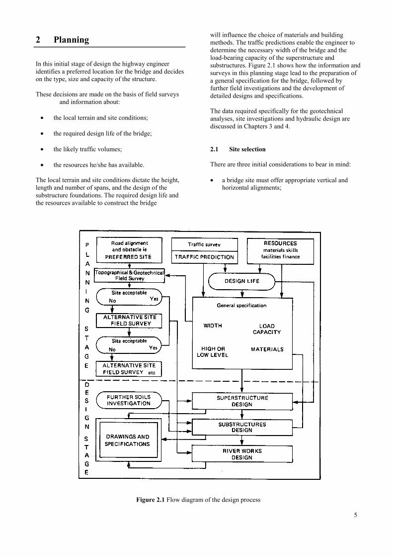
will influence the choice of materials and buildingmethods. The traffic predictions enable the engineer todetermine the necessary width of the bridge and theload-bearing capacity of the superstructure andsubstructures. Figure 2.1 shows how the information andsurveys in this planning stage lead to the preparation ofa general specification for the bridge, followed byfurther field investigations and the development ofdetailed designs and specifications.
The data required specifically for the geotechnicalanalyses, site investigations and hydraulic design arediscussed in Chapters 3 and 4.
2.1 Site selection
There are three initial considerations to bear in mind:
• a bridge site must offer appropriate vertical andhorizontal alignments;
Figure 2.1 Flow diagram of the design process
5
• its soils must be strong enough to ensure thestability of the structure;
• the bridge and its associated works should not havean adverse impact on adjoining land or buildings, orthemselves be susceptible to damage from the localenvironment.
For the highway engineer, rivers are the most commonobstructions needing to be bridged. Occasionally he/shemay be called upon to design a rail or road crossing butthese are relatively simple compared to river crossingsbecause they involve considerations only of height andspan, whereas the design of a river crossing has also totake hydraulic requirements into account.
2.1.1 River morphologyRivers are classed as either alluvial or incised.
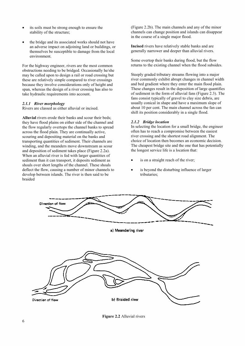
Alluvial rivers erode their banks and scour their beds;they have flood plains on either side of the channel andthe flow regularly overtops the channel banks to spreadacross the flood plain. They are continually active,scouring and depositing material on the banks andtransporting quantities of sediment. Their channels arewinding, and the meanders move downstream as scourand deposition of sediment takes place (Figure 2.2a).When an alluvial river is fed with larger quantities ofsediment than it can transport, it deposits sediment asshoals over short lengths of the channel. These shoalsdeflect the flow, causing a number of minor channels todevelop between islands. The river is then said to bebraided
(Figure 2.2b). The main channels and any of the minorchannels can change position and islands can disappearin the course of a single major flood.
Incised rivers have relatively stable banks and aregenerally narrower and deeper than alluvial rivers.
Some overtop their banks during flood, but the flowreturns to the existing channel when the flood subsides.
Steeply graded tributary streams flowing into a majorriver commonly exhibit abrupt changes in channel widthand bed gradient where they enter the main flood plain.These changes result in the deposition of large quantifiesof sediment in the form of alluvial fans (Figure 2.3). Thefans consist typically of gravel to clay size debris, areusually conical in shape and have a maximum slope ofabout 10 per cent. The main channel across the fan canshift its position considerably in a single flood.
2.1.2 Bridge locationIn selecting the location for a small bridge, the engineeroften has to reach a compromise between the easiestriver crossing and the shortest road alignment. Thechoice of location then becomes an economic decision.The cheapest bridge site and the one that has potentiallythe longest service life is a location that:
• is on a straight reach of the river;
• is beyond the disturbing influence of largertributaries;
Figure 2.2 Alluvial rivers6
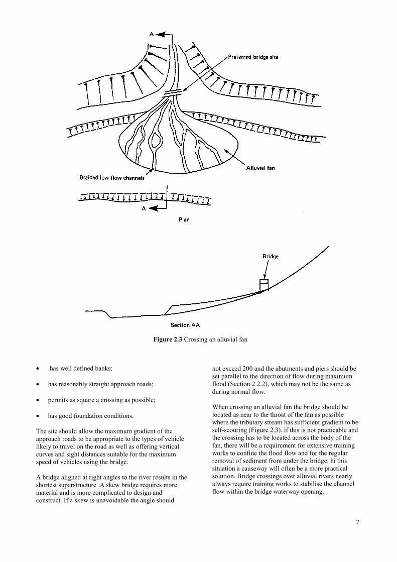
Figure 2.3 Crossing an alluvial fan
• .has well defined banks;
• has reasonably straight approach roads;
• permits as square a crossing as possible;
• has good foundation conditions.
The site should allow the maximum gradient of theapproach roads to be appropriate to the types of vehiclelikely to travel on the road as well as offering verticalcurves and sight distances suitable for the maximumspeed of vehicles using the bridge.
A bridge aligned at right angles to the river results in theshortest superstructure. A skew bridge requires morematerial and is more complicated to design andconstruct. If a skew is unavoidable the angle should
not exceed 200 and the abutments and piers should beset parallel to the direction of flow during maximumflood (Section 2.2.2), which may not be the same asduring normal flow.
When crossing an alluvial fan the bridge should belocated as near to the throat of the fan as possiblewhere the tributary stream has sufficient gradient to beself-scouring (Figure 2.3). if this is not practicable andthe crossing has to be located across the body of thefan, there will be a requirement for extensive trainingworks to confine the flood flow and for the regularremoval of sediment from under the bridge. hi thissituation a causeway will often be a more practicalsolution. Bridge crossings over alluvial rivers nearlyalways require training works to stabilise the channelflow within the bridge waterway opening.
7
2.2 Site conditions
Once the engineer has identified a likely site for thebridge, he/she needs to obtain field information on thelocal terrain and river conditions in addition to the soilinformation and hydraulic data that are outlined inChapters 3 and 4 The key points of field informationrelate to:
• the catchment area of the river;
• water levels;
• navigational and other clearance requirements.
2.2.1 Catchment areaThe extent of the river catchment area determines thearea to be included in plans and sections, and can beused to estimate flow volumes. If maps to an appropriatescale or aerial photographs are available, the limits ofthe catchment area can be marked on them and its totalsize calculated. Transparent squared graph paper isuseful for this purpose. In the absence of suitablecartography, the size of the catchment area and itsaverage gradient should be estimated by means of atraverse.
2.2.2 Water levelsInformation is needed on the highest known flood level,the ordinary flood level and the low water level at theproposed site.
The highest known flood level (HFL) should bedetermined by local observation wherever possible,supplemented by inquiries in the locality. The silt marksthat high floods generally leave on tree trunks andbuildings remain visible for several years. If there areold trees in the vicinity of the site, they should beexamined for the presence of small twigs left adhering tothe bark at high water levels. It is usually helpful to askpeople who have been living in the area for a long timeabout their recollections of particularly high floods, butthis source of information is variable in its reliability. Itis better to make such inquiries by talking to peopleindividually rather than in groups.
The ordinary flood level (OFL) is the level to which theriver normally rises during the wettest part of the year.
The low water level (LWL) is the level prevailing in theriver during dry weather. if there is little or no flow indry weather, the period during which the river bedremains dry should be noted.
2.2.3 Navigational and other clearancerequirements
The height of the bridge superstructure has to allow forthe passage of any regular or occasional river craft aswell as the clearance of floating debris at times of
8
flood. Even where a river is not used by regular traffic,drainage channels and other alluvial waterwaysperiodically require dredging and river-borne equipmentmay need to pass the bridge. Though it is unlikely thatriver maintenance equipment will travel when the riveris in full spate, this is the time when trees and otherfloating debris may be carried by floodwater. Experiencefrom other structures on the same river, together withinquiries locally, will help to determine the requiredclearance between the design flood level (Chapter 5,Introduction) and the underside of the superstructure(Section 5.2).
2.3 Plan and sections
The engineer should produce:
• a plan and longitudinal section of the river toscales of 1/1000 horizontal and 1/100 vertical;
• at least three cross-sections plotted to a naturalscale of 1/100, one at the proposed site and oneeach at the upstream and downstream limits of theplan.
Table 2.1 indicates the distances that should be coveredby the plan and longitudinal section in relation to thesize of the river catchment area. These distances may bereduced if large-scale aerial photographs are availableand show a simple river channel shape.
Table 2.1 Distances to be covered by site plans
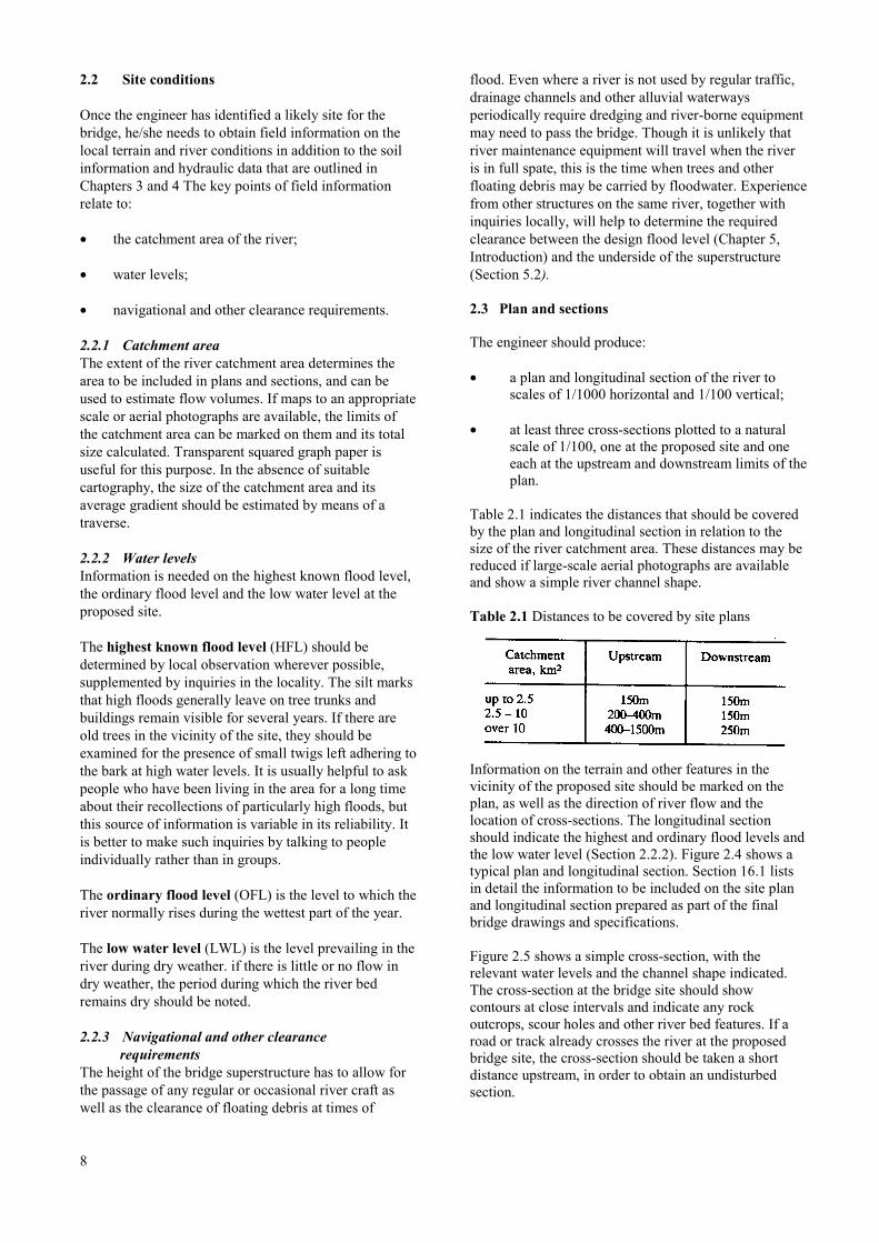
Information on the terrain and other features in thevicinity of the proposed site should be marked on theplan, as well as the direction of river flow and thelocation of cross-sections. The longitudinal sectionshould indicate the highest and ordinary flood levels andthe low water level (Section 2.2.2). Figure 2.4 shows atypical plan and longitudinal section. Section 16.1 listsin detail the information to be included on the site planand longitudinal section prepared as part of the finalbridge drawings and specifications.
Figure 2.5 shows a simple cross-section, with therelevant water levels and the channel shape indicated.The cross-section at the bridge site should showcontours at close intervals and indicate any rockoutcrops, scour holes and other river bed features. If aroad or track already crosses the river at the proposedbridge site, the cross-section should be taken a shortdistance upstream, in order to obtain an undisturbedsection.
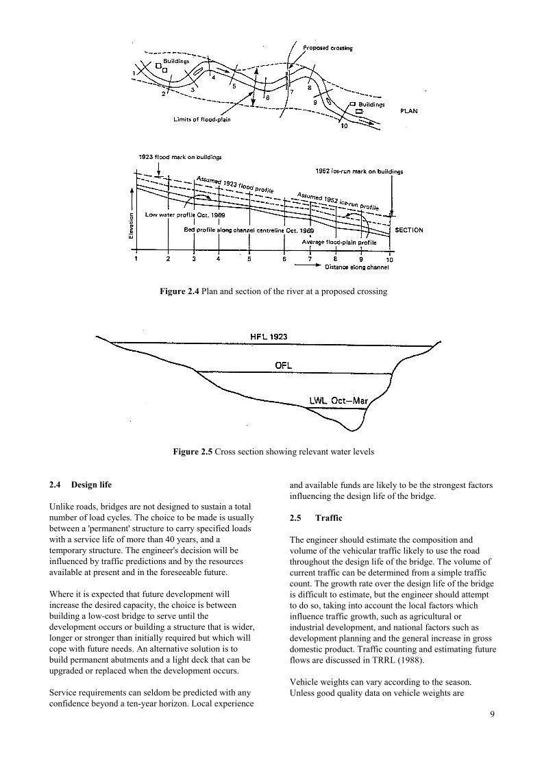
Figure 2.4 Plan and section of the river at a proposed crossing
Figure 2.5 Cross section showing relevant water levels
2.4 Design life
Unlike roads, bridges are not designed to sustain a totalnumber of load cycles. The choice to be made is usuallybetween a 'permanent' structure to carry specified loadswith a service life of more than 40 years, and atemporary structure. The engineer's decision will beinfluenced by traffic predictions and by the resourcesavailable at present and in the foreseeable future.
Where it is expected that future development willincrease the desired capacity, the choice is betweenbuilding a low-cost bridge to serve until thedevelopment occurs or building a structure that is wider,longer or stronger than initially required but which willcope with future needs. An alternative solution is tobuild permanent abutments and a light deck that can beupgraded or replaced when the development occurs.
Service requirements can seldom be predicted with anyconfidence beyond a ten-year horizon. Local experience
and available funds are likely to be the strongest factorsinfluencing the design life of the bridge.
2.5 Traffic
The engineer should estimate the composition andvolume of the vehicular traffic likely to use the roadthroughout the design life of the bridge. The volume ofcurrent traffic can be determined from a simple trafficcount. The growth rate over the design life of the bridgeis difficult to estimate, but the engineer should attemptto do so, taking into account the local factors whichinfluence traffic growth, such as agricultural orindustrial development, and national factors such asdevelopment planning and the general increase in grossdomestic product. Traffic counting and estimating futureflows are discussed in TRRL (1988).
Vehicle weights can vary according to the season.Unless good quality data on vehicle weights are
9
available it is advisable to carry out an axle weighingexercise at the time of year when the heaviest loads aretransported, as described in TRRL (1978).
2.6 Bridge width
Apart from bridges for special applications, there arethree alternative widths to be considered:
• single lane;
• one and a half lanes;
• two lanes.
2.6.1 Single lane bridgesSingle lane bridges are suitable for predicted trafficflows lower than about 200 vehicles per day. Theyinvolve only minimal disturbance to traffic flow andthere is normally no safety problem, given adequatesight distance and waiting areas on the bridgeapproaches and clear advance signing of the widthrestriction. The width clearance for vehicles is usually3.65m. Additional provision can be made for pedestriansand two-wheeled vehicles on one side of the roadway, oron both sides when the bridge is located close to avillage. Footways should be a minimum of 1.5m wide.
2.6.2 One and a half lane bridgesIn some districts there may be a preponderance of lighttraffic, with only the occasional bus or heavycommercial vehicle. In this situation, the most costeffective design may be a bridge allowing two lanes oflight traffic, but not wide enough for two large vehiclesto pass. This solution offers economies over a full, two-lane bridge in terms of both width and load carryingcapacity.
A carriageway width of 4.6m is sufficient for two lanesof light vehicles but restricts the loading to one lane ofheavy vehicles, which are normally 2.5m wide.Adequate sight distances, waiting areas and warningsigns are required at both ends of the bridge, and there islikely to be a need to make additional provision forpedestrians.
Some authorities consider this width of bridgedangerous and may give preference to a wider two lanebridge.
2.6.3 Two lane bridgesThese should be designed to conform to the appropriatenational standards in terms of load capacity, width andsafety provisions.
2.6.4 CulvertsCulverts occur more frequently than bridges and are notso noticeable to drivers on fast stretches of road. It isrecommended that carriageway width remains constantover culverts.
10
2.6.5 Low water crossingsLow water crossings are considered separately inChapter 7.
2.7 Paths for pedestrians and cyclists
Safety authorities recommend that segregated footwaysare provided for pedestrians to cross bridges, TRRL(1991). They are particularly necessary on long bridgesbuilt to minimum widths where the traffic is fast.
It is possible to add a pathway for pedestrians andcyclists by means of supports cantilevered from themain deck, but the engineer has to bear in mind theeffect of asymmetric loading should a large number ofpeople congregate on the pathway. An alternative andgenerally more satisfactory approach is to widen themain deck by about 2m and provide a suitable barrierand parapet, as discussed in Sections 9.2.10 and 11.4.
2.8 Design loading
Most countries have some form of design loadingstandards for bridges, but some have not yet determinedan appropriate standard for short span rural bridgeswhich carry low traffic volumes and weights. Theseshort span rural bridges often do not need to bedesigned for the heavy goods vehicles that are commonin industrial areas as an appropriate loadingspecification for a bridge is one which caters for theheaviest predicted loads expected during the life of thestructure.
This manual offers standard designs that conform withtwo of the most commonly adopted loading standards.These are the British Standard loading for 40 tonnegross weight vehicles (BS.HA.LOAD) and theAmerican AASHTO loading for 20 tonne gross weightvehicles (HS 20-44). These loading levels have beenused in the standard designs presented in the followingchapters and should be sufficient to cover the loadingrequirements of the majority of rural bridges.
2.8.1 BS.HA.LOAD (40 tonne maximum grossvehicle weight)
The BS.HA.LOAD loading was adopted from BritishStandard BS 5400 (BSI 1978). The loading includes 38tonne heavy goods vehicles as well as the newEuropean 40 tonne, five- and six-axle trailercombinations. The revised loading specifications, now arequirement for bridges in Britain, are presented in BD37 (Highways Agency 1988). The loading is presentedin the form of a uniformly distributed load imposed onthe full lane and a knife edge load placed across thelane in the most critical location and represents a fullyloaded lane with the worst combination of vehiclesexpected in the life of the bridge. The loading includesthe effect of impact
(80% on the heaviest axle), overloading (up to 40%)and a 10% contingency for future increases in trafficload and is therefore a conservative estimate of theworst expected loading. The range of vehicleconfigurations covered by this loading, as well as anindication of which vehicles are critical for each span,are given in BD 21 (Highways Agency 1997).
2.8.2 HS 20-44(20 tonne maximum gross vehicleweight)
Loading HS 20-44 has been taken from the AASHTOstandard (AASHTO 1983) to cover vehicles with amaximum gross vehicle weight of 20 tonnes. Most two-axle medium weight commercial vehicles are loadedwithin the 15 tonne AASHTO limits, but whenoverloaded these limits may be exceeded. HS 20-44 hastherefore been adopted here as a conservative standard.The vehicle configurations (axle weights, spacing, etc)covered by this loading are described in the AASHTOstandard.
Bridge loading specifications can vary considerablybetween countries. One reason for this is that standardsare frequently derived from the range of legal vehicleloads in that country. When choosing a standard to use,it is important to take into account the actual vehicleloads that may use the bridge. In some cases, these canbe higher than the maximum legal vehicle loads. The 40tonne loading (BS.HA.LOAD) should be used wheretraffic cannot be restricted to 20 tonne vehicles. Inaddition, it should be used where overloaded three axlelorries, forestry or quarry vehicles and constructionplant are likely to be in use.
In both of the above design standards, an allowance foreven heavier vehicles can be made by additionalloading requirements. These are not included in thestandard designs given in this manual. Where theseheavier vehicles are expected, the standard designs canbe checked, and modified appropriately, by a suitablyqualified engineer.
2.9 ResourcesThere are three categories of resources to beconsidered:
• design ability;
• skills for the various bridge construction processes;
• available materials.
2.9.1 DesignIt is the purpose of this manual to provide all thenecessary procedural guidance, tables, dimensions andmaterial specifications to enable a civil or mechanicalengineer with some field experience to prepareappropriate designs for small bridges. The
use of these procedures and tables will lead toserviceable, conservatively designed structures.Engineers with experience of bridge design may wishto carry out more of their own calculations or tointerpolate between recommended dimensions, and toproduce designs tailored more specifically toindividual requirements.
2.9.2 Trade skillsThe engineer should be conversant with the standardsof workmanship and supervision required forstructures using plain concrete, reinforced concrete,steel and timber. He/she should also be aware of thefacilities he/she has available for other functions suchas site investigations, and so will be the best person tojudge when external skills should be engaged forprocesses outside the experience of his ownworkforce. Working alongside crews specialising infields such as Site investigation, boring, piling orscaffolding can provide a useful opportunity tobroaden the skills of technicians and labourers in theengineer's own organisation.
2.9.3 MaterialsAll construction materials must either be found at orclose to the bridge site, or must be transported there.Bringing in heavy materials in long sections such assteel beams can be difficult, especially when thebridge is being constructed in advance of the road.
Steel panel bridges and steel beam bridges are oftenmade from imported parts and may be subject todelivery delays affecting key items. They may also bethe most expensive option, unless a substantial amountof the required materials can be found in the district ingood second-hand condition. Although panel bridgesare designed to be dismantled and used again, they arerarely used more than once.
The site investigations can be extended to include asearch for suitable aggregates for concrete and timberfor use in the deck or as temporary support duringconstruction. The planning stage includes makingprovision for processing the resources to be developedlocally and storing all the materials in a form that willprevent their deterioration.
2.10 References
AASHTO (1983). Standard specification forhighway bridges. Washington: American Associationof State Highway and Transportation Officials.
Highways Agency (1997). BD 21/97: Theassessment of highway bridges and structures.Design Manual for Roads and Bridges, Volume 3,Section 4, Part 3, Highways Agency, London.
11

Highways Agency (1988). BD 37/88: Loads forhighway bridges. Design Manual for Roads and Bridges,Volume 1, Section 3, Highways Agency, London.
TRRL (1978). A guide to the measurement of axle loadsin developing countries using a portable weighbridge.Road Note 40. Stationery Office, London.
TRL (1988). A guide to road project appraisal.Overseas Road Note ORN5. Transport ResearchLaboratory, Crowthorne.
TRL (1991). Towards safer roads in developingcountries - a guide for planners and engineers.Transport Research Laboratory, Crowthorne.
12
3. SITE INVESTIGATIONS
3.1 Methods of site investigation ……………………………………………………………………15
3.1.1 Test pits ………………………………………………………………………………15
3.1.2 Hand auger boring ……………………………………………………………………16
3.1.3 Cable percussion boring ………………………………………………………….…. 17
3.1A Rotary drilling ………………………………………………………………………..17
3.1.5 Geophysical surveying ……………………………………………………………… 17
3.1.6 Backfilling …………………………………………………………………………... 17
3.2 Extent of investigations …………………………………………………………………….…... 17
3.3 Sampling ………………………………………………………………………………………... 18
3.4 Soil testing ………………………………………………………………………………….……18
3.4.1 Field tests …………………………………………………………………………….18
3.4.1.1 Density measurements ……………………………………………………18
3.4.1.2 Shear vane tests ………………………………………………………….. 20
3.4.1.3 Penetration strength tests …………………………………………………20
3.4.1.4 Dynamic cone penetrometer soundings ……………………………….… 20
3A.1.5 Plate bearing tests ……………………………………………………….. 20
3.4.2 Laboratory tests ……………………………………………………………………... 20
3.5 Aggressive chemicals ……………………………………………………………………………20
3.6 Design review …………………………………………………………………………………... 21
3.7 References ……………………………………………………………………………………… 21
13

14
3 Site investigations
The weight of the traffic, superstructure, abutments andpiers will all be carried by the soils supporting theabutment and pier foundations. Th order to designappropriate foundations (Chapter 8) the engineer has todetermine the nature and location of the different soiltypes occurring at the site of the bridge and itsapproaches, to depths containing strata sufficientlystrong to support the bridge and embankments withoutsignificant deformation.
This information is obtained by analysing samplestaken from a grid of bore-holes or test pits covering thewhole of the proposed site, and by testing the samplesfor density, shear strength, plasticity and penetration, inorder to provide quantitative data for foundation design.
The level and nature of the ground water also affect thefoundation design and the engineer must take intoaccount the impact of bridge construction on the groundwater and hence the stability of nearby works andslopes.
Since the overall behaviour of the ground is oftendictated by planes or zones of weakness, it is possibleto obtain a large sample of material that may not beindicative of the behaviour of the mass. For this reason,and because of the frequent need to modify thesampling technique to suit the ground conditions, strictsupervision of sampling is essential.
Nearby cut slopes can reveal soil and rock types andtheir stability characteristics, as can old excavations andquarries. There may be embankments or buildings andother structures in the vicinity of the bridge site thathave a settlement history due to the presence ofcompressible or unstable soils.
This chapter contains several extracts from Tomlinson(1986), who states, 'An engineer undertaking a siteinvestigation may engage local labour for trial pitexcavation or hand auger boring, or he/she may employa contractor for boring and soil sampling. If laboratorytesting is required, the boring contractor can send thesamples to an independent testing laboratory. Theengineer then undertakes the soil mechanics analysisfor foundation design or he/she may ask the testinglaboratory to do this analysis. Alternatively, a specialistorganization offering comprehensive facilities forboring, sampling, field and laboratory testing, and soilmechanics analysis may undertake the wholeinvestigation. This is much to be preferred to the systemwhereby one organization does the borings, another thetesting, and yet another the analysis. A singleorganization has an advantage of providing the essentialcontinuity and close relationship between field,laboratory and office work. It also permits the boringand testing programme to be readily modified in thelight of information made available as the workproceeds.
Additional samples can be obtained as necessary fromsoil layers shown by laboratory testing to beparticularly significant. In situ testing can be substitutedfor laboratory testing if desired. In any case, theengineer responsible for the day-to-day direction of thefield and laboratory work should keep the objective ofthe investigation closely in mind and should make acontinuous appraisal of the data in the same way as isdone at the stage of preparing the report. In this wayvital information is not overlooked and the significanceof such features as weak soil layers, deep weathering ofrock formations and sub-artesian water pressure can bestudied in such greater detail as may be required, whilethe field work is still in progress.'
3.1 Methods of site investigation
This section outlines the following methods:
• test pits;
• hand auger boring;
• cable percussion boring;
• rotary drilling;
• geophysical surveying.
The descriptions are brief and intended only to remindthe engineer about the uses and limitations of the tests,which should be carried out under the supervision of anexperienced technician according to BSI (1981) orother accepted standard. Tomlinson (1986) andGeotechnical Control Office (1987) contain moredetailed descriptions.
3.1.1 Test pitsA test pit, which should be at least 1m square at thebottom, is a cheap and simple method of subsurfaceexploration. The pit is normally dug by hand, but amechanical excavator may be used to remove the bulkof the material before the sides and bottom are squaredand cleaned for examination. This method ofinvestigation supplies excellent data on subsurfaceconditions within the depth to which the pit isexcavated and enables a clear picture to be obtained ofthe stratification of the soils, the presence of any lensesor pockets of weaker material and the level of the watertable. The maximum practical depth to which a pit canbe excavated is about 3m; below a depth of about 1 .5mthe sides of the pit will require support or will need tobe excavated at a safe angle.
Pits excavated through cohesive soils below groundwater level are unlikely to need dewatering by pumps.They should be left open for some time so that seepagelines on the pit sides can indicate the ground waterlevel.
15
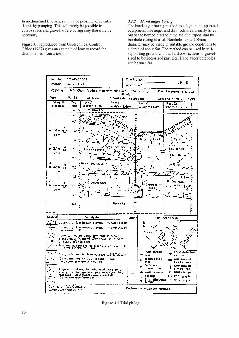
In medium and fine sands it may be possible to dewaterthe pit by pumping. This will rarely be possible incoarse sands and gravel, where boring may therefore benecessary.
Figure 3.1 reproduced from Geotechnical ControlOffice (1987) gives an example of how to record thedata obtained from a test pit.
3.1.2 Hand auger boringThe hand auger boring method uses light hand-operatedequipment. The auger and drill rods are normally liftedout of the borehole without the aid of a tripod, and noborehole casing is used. Boreholes up to 200mmdiameter may be made in suitable ground conditions toa depth of about 5m. The method can be used in self-supporting ground without hard obstructions or gravel-sized to boulder-sized particles. Hand auger boreholescan be used for
Figure 3.1 Trial pit log
16
ground water observations and to obtain disturbedsamples and small open-tube samples.
3.1.3 Cable percussion boringThis is an adaptation of standard well-boring methods,suitable for soil and weak rock. The sizes of boreholecasings and tools are generally 150mm, 200mm,250mm, and 300mm, giving a maximum boreholedepth of about 60m in suitable strata. The drill tools,worked on a wire rope using the clutch of the winch forthe percussive action, are a clay cutter for dry cohesivesoils, a shell or baler for cohesionless soils and a chiselfor breaking up rock and other hard layers. The claycutter and shell bring up disturbed material forlaboratory testing and identification of the strata.
3.1.4 Rotary drillingRotary drilling rigs are available in a wide range ofweights and power ratings. They require a certainexpertise in operation, not least because water suppliedto lubricate the drilling head can adversely affect thestability of the surrounding ground and the samplesobtained from the bore. Open hole drilling, in whichthe drill bit cuts all the material within the diameter ofthe borehole, is used for more rapid progress in hardmaterial. Better quality samples of soil and rock areobtained using core drilling, in which an annular bitfixed to the outer rotating tube of a core barrel cuts acore that is returned within the inner stationary tube ofthe barrel.
3.1.5 Geophysical surveyingGeophysical tests may be helpful in supplementing thedata obtained from test pits and bores, eg by tracing theboundary between two soil types, but they are rarelynecessary for the planning and design of small bridges.The tests, whether sonic, magnetic or seismic, requireexpert handling and interpretation, and should thereforebe entrusted to an organisation specialising in thiswork.
3.1.6 BackfillingPoorly compacted backfill will cause settlement at theground surface and can act as a path for ground water.For boreholes in dry ground it is possible to usecompacted soil as a fill material, though cement basedgrout is usually more successful. The back-fill ofexcavations can be compacted by using an excavatorbucket, but hand tamping will be required at corners.
Only temporary backfilling will be required whereabutment or pier foundations are to be constructed. Allother pits and boreholes should be properly reinstated.
3.2 Extent of investigations
The site investigations should reveal a clear pattern ofsoils, rock strata and ground water over the whole site.Strength tests are required in the soils that are to beloaded by the structure (Figure 3.2 and Section 8.3.3):these tests should be taken down below foundationlevel, or below all deposits that are unsuitable forfoundations, to a depth at least 1.5 times the expectedwidth of the foundation, unless bed-rock is reached andconfirmed by drilling with a rotary coring rig. Usually apenetration of 3m into the rock will be sufficient; inresidual profiles it may be necessary to drill farther toensure that the rock is not just a boulder or core stone.
At least three boreholes should be drilled for eachbridge abutment. Fewer bores may be permitted forpiers if a clear picture emerges of the strata and soilproperties. Each borehole and pit should be numberedand the numbers entered on a plan of the site.
3.3 Sampling
The choice of sampling technique depends on thepurpose for which the sample is required and thecharacter of the ground.
There are four main techniques for obtaining samples:
• taking disturbed samples from drill tools or fromexcavating equipment in the course of boring orexcavation
• drive sampling in which a tube or split tubesampler with a sharp cutting edge at its lower endis forced into the ground, either by static thrust orby dynamic impact
• rotary sampling, in which a tube with a cutter at itslower end is rotated into the ground, so producing acore sample
• taking block samples cut by hand from a trial pit,shaft or heading.
Samples obtained by the last three techniques will besufficiently intact to enable the ground structure withinthe sample to be examined. However, the quality ofthese samples can vary considerably, depending on thesampling technique and ground conditions, and mostsamples will exhibit some degree of disturbance.
Table 3.1 indicates the mass of sample required foridentification purposes, Atterburg tests, moisturecontent, sieve analysis and sulphate tests.
Care should be taken to ensure that samples are as pureand undisturbed as possible. Before a sample is taken,the bottom of the borehole or surface of the pit must becleared of loose or disturbed material. When
17
Table3.1 Soil sample mass required for identification
Soil type Mass requiredkg
Clay, silt, sand 2Fine & medium gravel 5Coarse gravel 30
taking undisturbed samples by drive sampling, it isnecessary to maintain the water level in the boreholeabove the surrounding ground water level, so as toprevent the sample being disturbed by a flow of waterinto the borehole due to the differential head.
Samples should be packed and labelled in appropriatecontainers, according to the laboratory testingprogramme. Block samples should be marked fororientation and protected from evaporation so far aspossible until they are properly wrapped and boxed.
Each sample should be labelled with a referencenumber for location, date, brief description and depthbelow ground level of the top and bottom of the sample.The sample reference numbers should be related to theborehole and pit numbers (Section 3.2)
3.4 Soil Testing
Table 3.2 sets out the basis on which soils are classifiedfor engineering purposes, and outlines simple field teststhat help identification. Laboratory tests of soil samplesand in situ field tests should be carried out according torecognised standards such as BSI (1981 and 1990).These tests include sieve analysis of non-cohesive soils,liquid limit and plastic limit tests of cohesive soils,density tests, strength tests and acidity tests.
Some presumed bearing values are listed in Chapter 8,but it is recommended that wherever laboratory facilitiesand field equipment are available, the most appropriateof the tests outlined in Section 3.4.1 are carried out foreach site.
3.4.1 Field testsThese may include:
density measurements; shear vane tests; penetration strength tests; dynamic cone penetrometer soundings; plate bearing tests.
It is assumed that if the facilities for these tests areavailable, the procedures are known and need not be
18
described in detail here. Relevant standards are BSI(1981) and ASTM(1985).
3.4.1.1 Density measurementsBulk density of soils and rock is measured by sand orwater replacement methods or by nuclear methods.
3.4.1.2 Shear vane testsShear vane tests are usually confined to uniform,cohesive, fully saturated soils. The presence of evensmall amounts of coarse particles, rootlets or thinlaminations of sand may lead to unreliable results.
3.4.1.3 Penetration strength testsThe strength of coarse-grained, non-cohesive soils canbe assessed by the Standard Penetration test using apercussion boring rig and a split-barrel sampler. The Nvalue obtained is used directly in the designcalculations outlined in Chapter 8. The value is thenumber of blows required to drive the sampler 300mminto the layer under study, and it may be affected bylarge stones and rock. For this reason, any very highvalues obtained by this method should be treated withsuspicion. Table 3.3 indicates an approximatecorrelation between N values and the relative density ofgranular materials.
3.4.1.4 Dynamic cone penetrometer soundingsThe Dynamic Cone Penetrometer (DCP) is cheap andquick to use, and it causes minimal disturbance to theground. It can be applied between boreholes or test pitsto obtain a continuous profile of soil layers, or to findthe boundaries of boulders. DCP tests should be madeclose to each borehole or test pit, to provide acorrelation between soil types and penetration specificto the locality of the site, and then at small intervalsbetween boreholes and test pits. Table 3A shows atypical correlation between DCP and SPT values.
3.4.1.5 Plate bearing testsThere are a number of procedures for measuring thebearing capacity of soils and weak rocks by the use of asteel plate to which either a continuous load or aconstant rate of penetration is applied, BSI (1990). Ifpossible the plate should fill the borehole and bebedded on undisturbed material: where the diameter ofthe plate is significantly less than the diameter of theborehole, the results of the test are hard to interpret.Ground water should be at its natural level during thetest, which may make seating of the plate in the bottomof the borehole difficult. Since the resulting bearingcapacity applies only to the soil or rock immediatelybelow the plate, a number of tests will be required tocover the surface area and depth of material to bestressed by an abutment or pier (Figure 3.2)

19
Tabl
e 3.
2 G
ener
al b
asis
for f
ield
iden
tific
atio
n an
d cl
assi
ficat
ion
of so
ils
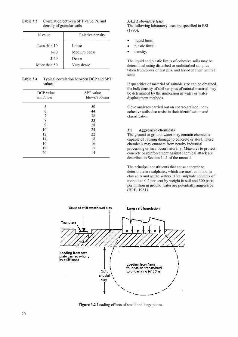
Table 3.3 Correlation between SPT value, N, anddensity of granular soils
N value Relative density
Less than 10 Loose1-30 Medium dense3-50 Dense
More than 50 Very dense
Table 3.4 Typical correlation between DCP and SPTvalues
DCP value SPT valuemm/blow blows/300mm
5 506 447 388 339 28
10 2412 2214 1816 1618 1520 14
3.4.2 Laboratory testsThe following laboratory tests are specified in BSI(1990):
• liquid limit;• plastic limit;• density.
The liquid and plastic limits of cohesive soils may bedetermined using disturbed or undisturbed samplestaken from bores or test pits, and tested in their naturalstate.
If quantities of material of suitable size can be obtained,the bulk density of soil samples of natural material maybe determined by the immersion in water or waterdisplacement methods.
Sieve analyses carried out on coarse-grained, non-cohesive soils also assist in their identification andclassification.
3.5 Aggressive chemicalsThe ground or ground water may contain chemicalscapable of causing damage to concrete or steel. Thesechemicals may emanate from nearby industrialprocessing or may occur naturally. Measures to protectconcrete or reinforcement against chemical attack aredescribed in Section 14.1 of the manual.
The principal constituents that cause concrete todeteriorate are sulphates, which are most common inclay soils and acidic waters. Total sulphate contents ofmore than 0.2 per cent by weight in soil and 300 partsper million in ground water are potentially aggressive(BRE, 1981).
Figure 3.2 Loading effects of small and large plates
20

Corrosion of metal is caused by electrolytic or otherchemical or biological action. In industrial areas,corrosive action may result from individual wasteproducts dumped on the site. In river and marine works,the possible corrosive action of water, sea water andother saline waters, and industrial effluents may alsorequire investigation. In a marine environment, themost severe corrosion is found in the 'splash zone' thatis only wetted occasionally. The saline concentration inground water near the sea may approach that of seawater, particularly where land has been reclaimed. Nearestuaries, there may be an adverse condition caused byalternation of water of different salinities.
Laboratory tests to assess the aggressiveness of theground and ground water against Portland cementconcrete include determination of pH value andsulphate content (B SI, 1990). Since the pH value maybe altered if there is a delay between sampling andtesting, determinations should be made in the fieldwhenever possible.
Water sampled from boreholes may be altered by theflushing water used in drilling, or by other flushingmedia employed: this means that sulphate and aciditytests carried out on samples from boreholes may not berepresentative unless special precautions are taken.
3.6 Design reviewThere is often difficulty in specifying ground conditionsbefore the excavations for construction are complete.For this reason the engineer should be prepared toreview his plans, both during the site investigation andduring construction, if evidence is found of unexpectedsoil conditions.
3.7 ReferencesASTM (1985). Annual book of ASTM standards, vol0408. Philadelphia: American Society for Testing andMaterials.
BRE (1981). Concrete in sulphate bearing soils andground waters. Digest No 250. Watford: BuildingResearch Establishment.
BSI (1981). Code of practice for site investigations. BS5930. London: British Standards Institution.
BSI (1990). Methods of test for soils for civilengineering purposes. BS 1377. London: BritishStandards Institution.
Geotechnical Control Office (1987). Guide to siteinvestigation , Geoguide 2. Hong Kong: CivilEngineering Services Department.
Tomlinson M J (1986). Foundation design andconstruction, fifth edition. Singapore: LongmanSingapore Publishers Pte Ltd.
2121

22

4. RIVER HYDRAULICS
4.1 Flow velocity ………………………………………………………………………………………….. 25
4.1.1 Direct measurement ……………………………………………………………………….. 25
4.1.2 Calculation using bed characteristics ……………………………………………………… 26
4.2 Flow volume (discharge) ……………………………………………………………………………… 26
4.2.1 Area-velocity method ……………………………………………………………………... 26
4.2.2 Orifice formula ……………………………………………………………………………. 26
4.2.3 Other methods …………………………………………………………………………….. 29
4.3 References …………………………………………………………………………………………….. 29
Appendix 4.1 …………………………………………………………………………………………………….. 30
Appendix 4.2 …………………………………………………………………………………………………….. 30
23

24
4 River hydraulics
This chapter deals with the acquisition of the hydraulicdata necessary for the efficient design of a rivercrossing in relation to the flow characteristics of theriver (Chapter 5). The engineer has to ensure that theflow of water can pass the structure without causingdamage to the bridge, the road embankment or thesurrounding land. Damage can occur in a number ofways:
• the river may react against obstructions such as piersand abutments, and scour beneath them causingfailure;
• the approach embankments may act as a dam duringhigh floods, sustaining damage or causing moreextensive flooding upstream;
• a river flowing on a shifting path may bypass abridge and cut a new channel across the highway;
• a river may over-top a bridge if sufficient clearanceis not provided.
In order to design a structure that avoids these problemsand costs no more than is necessary, the hydrauliccharacteristics of the river must be understood andquantified. The most economical structure is usuallyone which is just wide and high enough toaccommodate the design flood, minimising the totalcost of abutments, piers, superstructure, approachembankments, relief culverts and river training works.
The hydraulic data required for the design processdetailed in Chapters 5 and 6 relate to:
• design flood level (defined in Chapter 5), flowvolume and velocity;
• maximum flood level, flow volume and velocity;
• bed characteristics - particle size, vegetation;
• channel shape and flood plain width;
• sedimentation and meander characteristics;
• navigational requirements and clearance of floatingdebris.
Flow velocity measurement and estimation are treatedin Section 4.1, flow volume calculation in Section 4.2.Characteristics of the river bed and navigationalrequirements were discussed in Chapter 2. Flood levelsand channel shape are drawn on the longitudinal andcross sections described in Section 2.3.
Using the hydraulic data, calculations may be made todetermine:
• the geometry of waterway required at the bridgesite;
• the backwater caused by the restriction of flow dueto piers and abutments;
• the scour caused by the restriction;
• the river training works required.
4.1 Flow velocity
4.L1 Direct measurementThough it may he difficult to measure flow velocitiesdirectly during a flood, the engineer should attempt todo so wherever possible, because this is the criticalvalue and alternative methods of estimating a maximumvalue are less accurate.
After a suitable method of depositing and retrieving afloat on the river has been contrived, its travel shouldbe timed over a distance of at least four times thechannel width on a straight reach of preferably uniformsection. If the shape of the channel is complex,velocities should be measured at several stations acrossthe width.
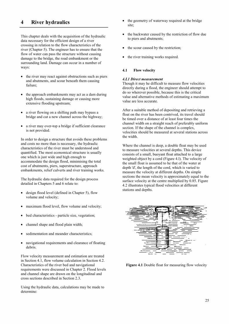
Where the channel is deep, a double float may be usedto measure velocities at several depths. This deviceconsists of a small, buoyant float attached to a largeweighted object by a cord (Figure 4.l). The velocity ofthe small float is assumed to he that of the water atdepth 'd', the length of the cord, which is varied tomeasure the velocity at different depths. On simplesections the mean velocity is approximately equal to thesurface velocity at the centre multiplied by 0.85. Figure4.2 illustrates typical flood velocities at differentstations and depths.
Figure 4.1 Double float for measuring flow velocity
25
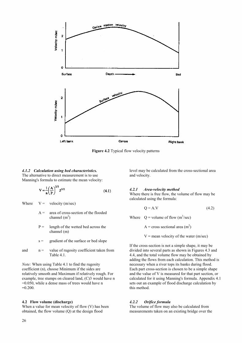
Figure 4.2 Typical flow velocity patterns
4.1.2 Calculation using bed characteristics.The alternative to direct measurement is to useManning's formula to estimate the mean velocity:
Where V = velocity (m/sec)
A = area of cross-section of the floodedchannel (m2)
P = length of the wetted bed across thechannel (m)
s = gradient of the surface or bed slope
and n = value of rugosity coefficient taken fromTable 4.1.
Note: When using Table 4.1 to find the rugositycoefficient (n), choose Minimum if the sides arerelatively smooth and Maximum if relatively rough. Forexample, tree stumps on cleared land, (C)3 would have n=0.050, while a dense mass of trees would have n=0.200.
4.2 Flow volume (discharge)When a value for mean velocity of flow (V) has beenobtained, the flow volume (Q) at the design flood
26
level may be calculated from the cross-sectional areaand velocity.
4.2.1 Area-velocity methodWhere there is free flow, the volume of flow may becalculated using the formula:
Q = A.V (4.2)
Where Q = volume of flow (m3/sec)
A = cross sectional area (m2)
V = mean velocity of the water (m/sec)
If the cross-section is not a simple shape, it may bedivided into several parts as shown in Figures 4.3 and4.4, and the total volume flow may be obtained byadding the flows from each calculation. This method isnecessary when a river tops its banks during flood.Each part cross-section is chosen to be a simple shapeand the value of V is measured for that part section, orcalculated for it using Manning's formula. Appendix 4.1sets out an example of flood discharge calculation bythis method.
4.2.2 Orifice formulaThe volume of flow may also be calculated frommeasurements taken on an existing bridge over the
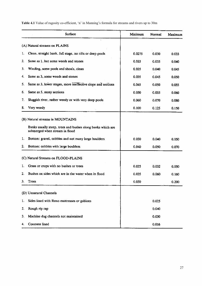
Table 4.1 Value of rugosity co-efficient, ‘n’ in Manning’s formula for streams and rivers up to 30m
27
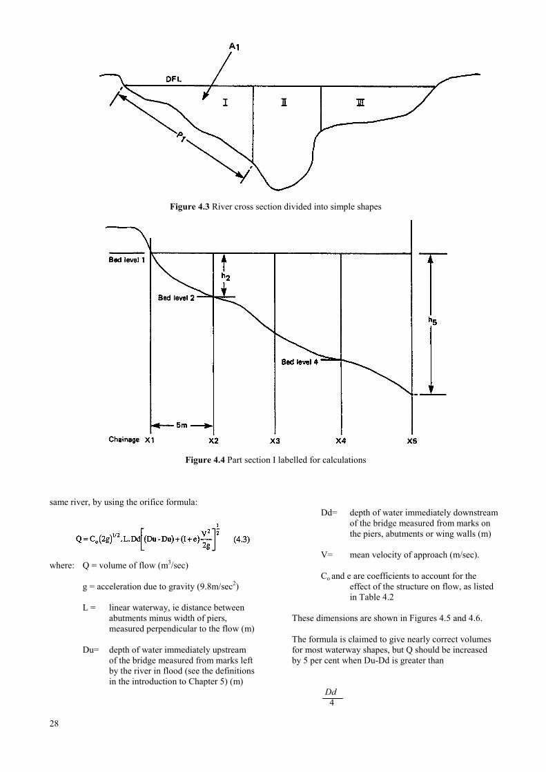
Figure 4.3 River cross section divided into simple shapes
Figure 4.4 Part section I labelled for calculations
same river, by using the orifice formula:
where: Q = volume of flow (m3/sec)
g = acceleration due to gravity (9.8m/sec2)
L = linear waterway, ie distance betweenabutments minus width of piers,measured perpendicular to the flow (m)
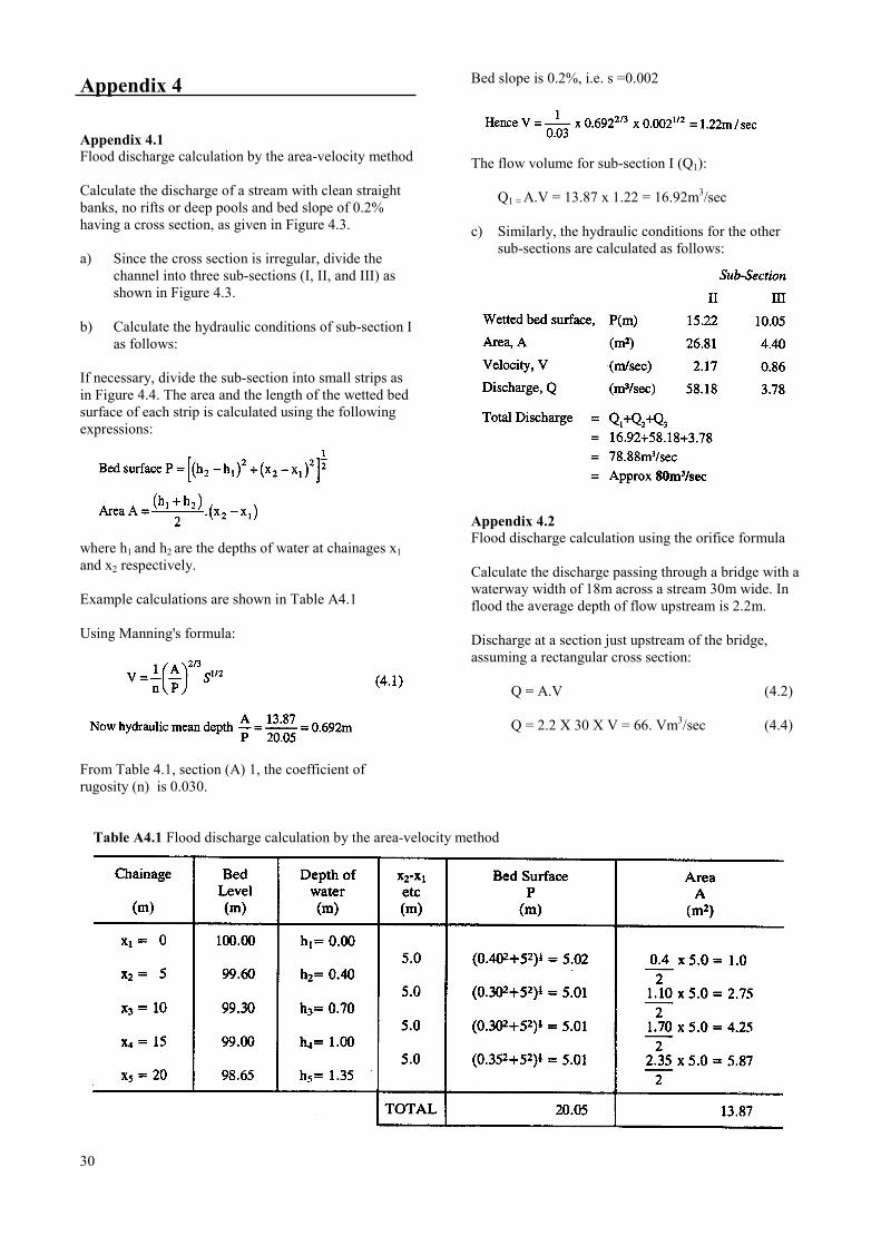
Du= depth of water immediately upstreamof the bridge measured from marks leftby the river in flood (see the definitionsin the introduction to Chapter 5) (m)
28
Dd= depth of water immediately downstreamof the bridge measured from marks onthe piers, abutments or wing walls (m)
V= mean velocity of approach (m/sec).
Co and e are coefficients to account for theeffect of the structure on flow, as listedin Table 4.2
These dimensions are shown in Figures 4.5 and 4.6.
The formula is claimed to give nearly correct volumesfor most waterway shapes, but Q should be increasedby 5 per cent when Du-Dd is greater than
Dd 4
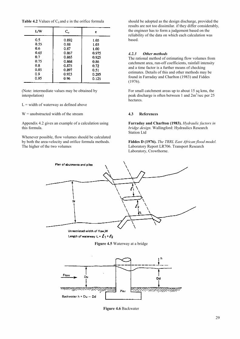
Table 4.2 Values of C0 and e in the orifice formula
(Note: intermediate values may be obtained byinterpolation)
L = width of waterway as defined above
W = unobstructed width of the stream
Appendix 4.2 gives an example of a calculation usingthis formula.
Whenever possible, flow volumes should be calculatedby both the area-velocity and orifice formula methods.The higher of the two volumes
should be adopted as the design discharge, provided theresults are not too dissimilar. if they differ considerably,the engineer has to form a judgement based on thereliability of the data on which each calculation wasbased.
4.2.3 Other methodsThe rational method of estimating flow volumes fromcatchment area, run-off coefficients, rainfall intensityand a time factor is a further means of checkingestimates. Details of this and other methods may befound in Farraday and Charlton (1983) and Fiddes(1976).
For small catchment areas up to about 15 sq kms, thepeak discharge is often between 1 and 2m3/sec per 25hectares.
4.3 References
Farraday and Charlton (1983). Hydraulic factors inbridge design. Wallingford: Hydraulics ResearchStation Ltd
Fiddes D (1976). The TRRL East African flood model.Laboratory Report LR706. Transport ResearchLaboratory, Crowthorne.
Figure 4.5 Waterway at a bridge
Figure 4.6 Backwater
29
Appendix 4
Appendix 4.1Flood discharge calculation by the area-velocity method
Calculate the discharge of a stream with clean straightbanks, no rifts or deep pools and bed slope of 0.2%having a cross section, as given in Figure 4.3.
a) Since the cross section is irregular, divide thechannel into three sub-sections (I, II, and III) asshown in Figure 4.3.
b) Calculate the hydraulic conditions of sub-section Ias follows:
If necessary, divide the sub-section into small strips asin Figure 4.4. The area and the length of the wetted bedsurface of each strip is calculated using the followingexpressions:
where h1 and h2 are the depths of water at chainages x1and x2 respectively.
Example calculations are shown in Table A4.1
Using Manning's formula:
From Table 4.1, section (A) 1, the coefficient ofrugosity (n) is 0.030.
Bed slope is 0.2%, i.e. s =0.002
The flow volume for sub-section I (Q1):
Q1 = A.V = 13.87 x 1.22 = 16.92m3/sec
c) Similarly, the hydraulic conditions for the othersub-sections are calculated as follows:
Appendix 4.2Flood discharge calculation using the orifice formula
Calculate the discharge passing through a bridge with awaterway width of 18m across a stream 30m wide. Inflood the average depth of flow upstream is 2.2m.
Discharge at a section just upstream of the bridge,assuming a rectangular cross section:
Q = A.V (4.2)
Q = 2.2 X 30 X V = 66. Vm3/sec (4.4)
Table A4.1 Flood discharge calculation by the area-velocity method
30

Discharge at a section just downstream of the bridgewill be the same and will be given by the orificeformula:
31

32
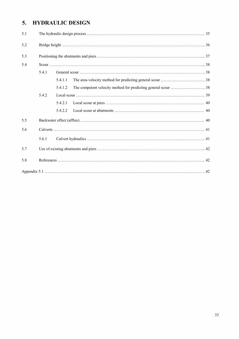
5. HYDRAULIC DESIGN
5.1 The hydraulic design process ……………………………………………………………………………. 35
5.2 Bridge height …………………………………………………………………………………………….. 36
5.3 Positioning the abutments and piers ……………………………………………………………………... 37
5.4 Scour ……………………………………………………………………………………………………... 38
5.4.1 General scour ………………………………………………………………………………….38
5.4.1.1 The area-velocity method for predicting general scour …………………………… 38
5.4.1.2 The competent velocity method for predicting general scour …………………….. 38
5.4.2 Local scour …………………………………………………………………………………… 39
5.4.2.1 Local scour at piers ……………………………………………………………….. 40
5.4.2.2 Local scour at abutments …………………………………………………………. 40
5.5 Backwater effect (afflux) ………………………………………………………………….…………….. 40
5.6 Culverts ………………………………………………………………………………………………….. 41
5.6.1 Culvert hydraulics ……………………………………………………………………………. 41
5.7 Use of existing abutments and piers ……………………………………………………………………... 42
5.8 References ……………………………………………………………………………………………….. 42
Appendix 5.1 …………………………………………………………………………………………………………42
33

34
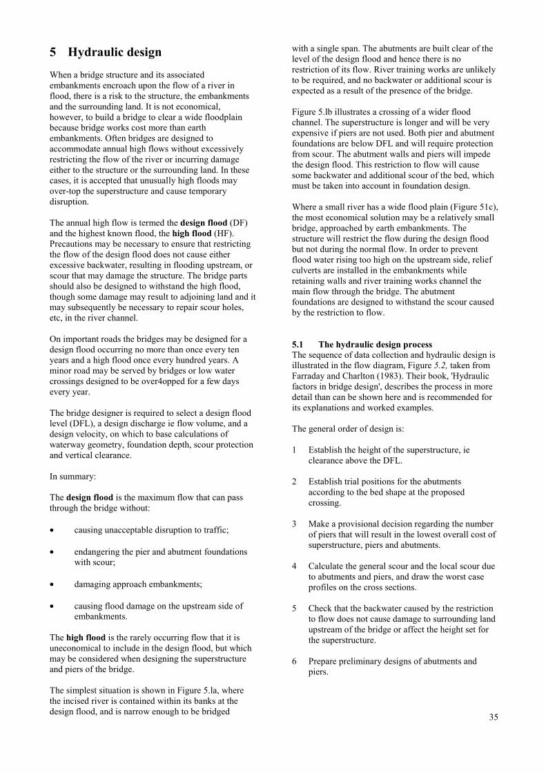
5 Hydraulic design
When a bridge structure and its associatedembankments encroach upon the flow of a river inflood, there is a risk to the structure, the embankmentsand the surrounding land. It is not economical,however, to build a bridge to clear a wide floodplainbecause bridge works cost more than earthembankments. Often bridges are designed toaccommodate annual high flows without excessivelyrestricting the flow of the river or incurring damageeither to the structure or the surrounding land. In thesecases, it is accepted that unusually high floods mayover-top the superstructure and cause temporarydisruption.
The annual high flow is termed the design flood (DF)and the highest known flood, the high flood (HF).Precautions may be necessary to ensure that restrictingthe flow of the design flood does not cause eitherexcessive backwater, resulting in flooding upstream, orscour that may damage the structure. The bridge partsshould also be designed to withstand the high flood,though some damage may result to adjoining land and itmay subsequently be necessary to repair scour holes,etc, in the river channel.
On important roads the bridges may be designed for adesign flood occurring no more than once every tenyears and a high flood once every hundred years. Aminor road may be served by bridges or low watercrossings designed to be over4opped for a few daysevery year.
The bridge designer is required to select a design floodlevel (DFL), a design discharge ie flow volume, and adesign velocity, on which to base calculations ofwaterway geometry, foundation depth, scour protectionand vertical clearance.
In summary:
The design flood is the maximum flow that can passthrough the bridge without:
• causing unacceptable disruption to traffic;
• endangering the pier and abutment foundationswith scour;
• damaging approach embankments;
• causing flood damage on the upstream side ofembankments.
The high flood is the rarely occurring flow that it isuneconomical to include in the design flood, but whichmay be considered when designing the superstructureand piers of the bridge.
The simplest situation is shown in Figure 5.la, wherethe incised river is contained within its banks at thedesign flood, and is narrow enough to be bridged
with a single span. The abutments are built clear of thelevel of the design flood and hence there is norestriction of its flow. River training works are unlikelyto be required, and no backwater or additional scour isexpected as a result of the presence of the bridge.
Figure 5.lb illustrates a crossing of a wider floodchannel. The superstructure is longer and will be veryexpensive if piers are not used. Both pier and abutmentfoundations are below DFL and will require protectionfrom scour. The abutment walls and piers will impedethe design flood. This restriction to flow will causesome backwater and additional scour of the bed, whichmust be taken into account in foundation design.
Where a small river has a wide flood plain (Figure 51c),the most economical solution may be a relatively smallbridge, approached by earth embankments. Thestructure will restrict the flow during the design floodbut not during the normal flow. In order to preventflood water rising too high on the upstream side, reliefculverts are installed in the embankments whileretaining walls and river training works channel themain flow through the bridge. The abutmentfoundations are designed to withstand the scour causedby the restriction to flow.
5.1 The hydraulic design processThe sequence of data collection and hydraulic design isillustrated in the flow diagram, Figure 5.2, taken fromFarraday and Charlton (1983). Their book, 'Hydraulicfactors in bridge design', describes the process in moredetail than can be shown here and is recommended forits explanations and worked examples.
The general order of design is:
1 Establish the height of the superstructure, ieclearance above the DFL.
2 Establish trial positions for the abutmentsaccording to the bed shape at the proposedcrossing.
3 Make a provisional decision regarding the numberof piers that will result in the lowest overall cost ofsuperstructure, piers and abutments.
4 Calculate the general scour and the local scour dueto abutments and piers, and draw the worst caseprofiles on the cross sections.
5 Check that the backwater caused by the restrictionto flow does not cause damage to surrounding landupstream of the bridge or affect the height set forthe superstructure.
6 Prepare preliminary designs of abutments andpiers.
35
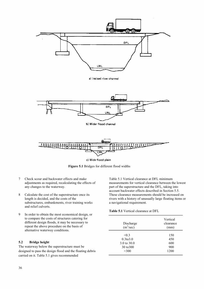
Figure 5.1 Bridges for different flood widths
7 Check scour and backwater effects and makeadjustments as required, recalculating the effects ofany changes to the waterway.
8 Calculate the cost of the superstructure once itslength is decided, and the costs of thesubstructures, embankments, river training worksand relief culverts.
9 In order to obtain the most economical design, orto compare the costs of structures catering fordifferent design floods, it may be necessary torepeat the above procedure on the basis ofalternative waterway conditions.
5.2 Bridge heightThe waterway below the superstructure must bedesigned to pass the design flood and the floating debriscarried on it. Table 5.1 gives recommended
36
Table 5.1 Vertical clearance at DFL minimummeasurements for vertical clearance between the lowestpart of the superstructure and the DFL, taking intoaccount backwater effects described in Section 5.5.These clearance measurements should be increased onrivers with a history of unusually large floating items ora navigational requirement.
Table 5.1 Vertical clearance at DFL
VerticalDischarge clearance(m3/sec) (mm)
<0.3 1500.3to3.0 450
3.0 to 30.0 60030 to300 900 >300 1200
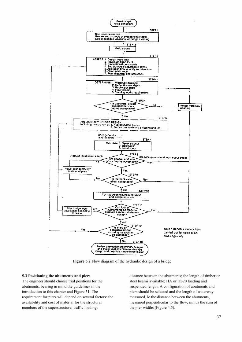
Figure 5.2 Flow diagram of the hydraulic design of a bridge
5.3 Positioning the abutments and piersThe engineer should choose trial positions for theabutments, bearing in mind the guidelines in theintroduction to this chapter and Figure 51. Therequirement for piers will depend on several factors: theavailability and cost of material for the structuralmembers of the superstructure; traffic loading;
distance between the abutments; the length of timber orsteel beams available; HA or HS20 loading andsuspended length. A configuration of abutments andpiers should be selected and the length of waterwaymeasured, ie the distance between the abutments,measured perpendicular to the flow, minus the sum ofthe pier widths (Figure 4.5).
37
Using these measurements and the estimates orcalculations of flow volume and velocity, outlined inSections 4.1 and 4.2, the engineer can calculate thelikely scour and backwater effects. If these proveunacceptable, a different configuration of abutmentsand piers should be tried.
5.4 ScourScour is the erosive effect of water flow on the riverbed or banks. Bridge works may alter the existing scourpattern by restricting the free flow of the stream and/orcausing local changes to the current. Approximatelyhalf of all river bridge failures are due to scour alone.
There are four types of scour:
• natural scour and channel shifting on alluvial rivers(Section 2.1.1);
• scour caused by changes to the river channelupstream or downstream of the bridge site;
• 'general' scour caused by reduction in the channelwidth at bridge works;
• 'local' scour at the base of piers, abutments andriver training works where these divert the generalflow.
Examination of the river at the bridge site and at anyexisting structures, preferably during and soon after atime of flood, will indicate if and where river trainingworks are required to combat channel shifting and toguide the flow through the waterway at the bridge. Anychanges to the river channel should be considered aslikely to affect the proposed structure and other nearbystructures on the river by changing scour patterns.
At the bridge site estimates are required for generalscour and local scour.
5.4.1 General scourThere are many relationships that can be used to predictgeneral scour. All of them assume a fairly simple riverchannel shape. At complex locations, particularly nearthe junction of two streams, these methods are knownto be inaccurate.
5.4.1.1 The area-velocity method for predictinggeneral scour
Despite the rise in water level on the upstream side of abridge during flood, the flow through the structure isassumed to be equal to the unrestricted flow (Section4.2), as calculated on the basis of velocity measurement(Section 4.1.1) or estimation (Section 4.1.2).
38
To predict the likely general scour of a river bedbetween confined banks or abutments, a probable scourline is drawn on the cross-section at the bridge:the area (A) and wetted perimeter (P) below the designflood level are measured as explained in Section 4.2.Water velocity is given by Manning's formula,
where n is Manning's rugosity coefficient found inTable 4.1 and
s is the gradient of the water or average bedgradient.
This process is repeated, ie probable scour lines aredrawn and the corresponding water velocities calculateduntil the product of calculated V and area A isapproximately the same as the unrestricted discharge.The shape of the additional scour area should beadjusted as shown in Figure 5.3.
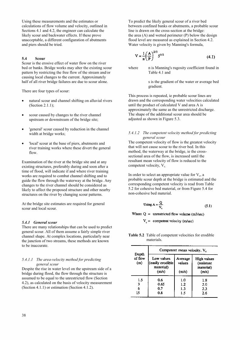
5.4.1.2 The competent velocity method for predictinggeneral scour
The competent velocity of flow is the greatest velocitythat will not cause scour to the river bed. In thismethod, the waterway at the bridge, ie the cross-sectional area of the flow, is increased until theresultant mean velocity of flow is reduced to thecompetent velocity, Vc.
In order to select an appropriate value for Vc, aprobable scour depth at the bridge is estimated and thecorresponding competent velocity is read from Table5.2 for cohesive bed material, or from Figure 5.4 fornon-cohesive bed material.
Table 5.2 Table of competent velocities for erodiblematerials.
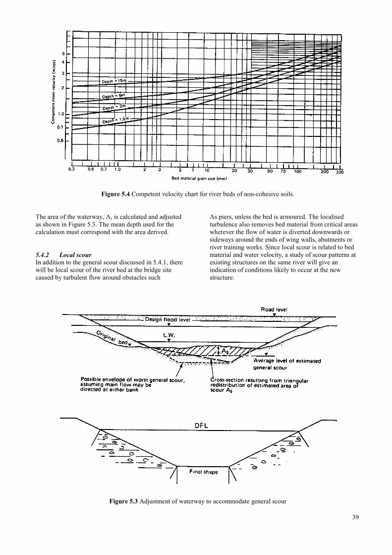
Figure 5.4 Competent velocity chart for river beds of non-cohesive soils.
The area of the waterway, A, is calculated and adjustedas shown in Figure 5.3. The mean depth used for thecalculation must correspond with the area derived.
5.4.2 Local scourIn addition to the general scour discussed in 5.4.1, therewill be local scour of the river bed at the bridge sitecaused by turbulent flow around obstacles such
As piers, unless the bed is armoured. The localisedturbulence also removes bed material from critical areaswherever the flow of water is diverted downwards orsideways around the ends of wing walls, abutments orriver training works. Since local scour is related to bedmaterial and water velocity, a study of scour patterns atexisting structures on the same river will give anindication of conditions likely to occur at the newstructure.
Figure 5.3 Adjustment of waterway to accommodate general scour
39
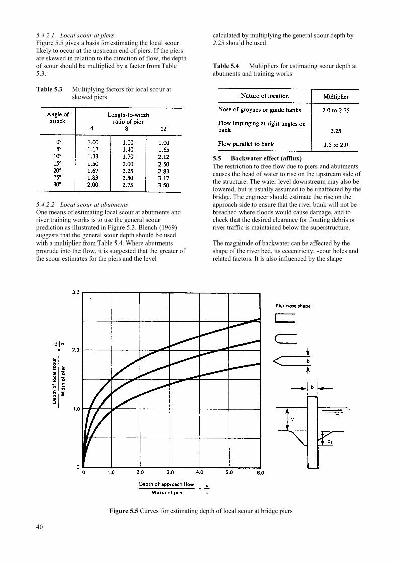
5.4.2.1 Local scour at piersFigure 5.5 gives a basis for estimating the local scourlikely to occur at the upstream end of piers. If the piersare skewed in relation to the direction of flow, the depthof scour should be multiplied by a factor from Table5.3.
Table 5.3 Multiplying factors for local scour atskewed piers
5.4.2.2 Local scour at abutmentsOne means of estimating local scour at abutments andriver training works is to use the general scourprediction as illustrated in Figure 5.3. Blench (1969)suggests that the general scour depth should be usedwith a multiplier from Table 5.4. Where abutmentsprotrude into the flow, it is suggested that the greater ofthe scour estimates for the piers and the level
calculated by multiplying the general scour depth by2.25 should be used
Table 5.4 Multipliers for estimating scour depth atabutments and training works
5.5 Backwater effect (afflux)The restriction to free flow due to piers and abutmentscauses the head of water to rise on the upstream side ofthe structure. The water level downstream may also belowered, but is usually assumed to be unaffected by thebridge. The engineer should estimate the rise on theapproach side to ensure that the river bank will not bebreached where floods would cause damage, and tocheck that the desired clearance for floating debris orriver traffic is maintained below the superstructure.
The magnitude of backwater can be affected by theshape of the river bed, its eccentricity, scour holes andrelated factors. It is also influenced by the shape
Figure 5.5 Curves for estimating depth of local scour at bridge piers
40
of the bridge works, ie by any skew, river training,embankments and relief culverts. For simpleconfigurations, a good estimate may be made using theformula:
where h = afflux (m)V = average velocity of flow (m/sec)g = acceleration due to gravity
(9.8m/sec2)W = unobstructed width of the stream (m)L = linear waterway as defined in Section
4.2.2 (m)C = coefficient of discharge through the
bridge, taken as 0.7 for sharp entryand 0.9 for bell mouthed entry.
The formula (5.2) is taken from Victor (1980). Moredetailed methods of calculation, including use of theorifice formula, are found in Bradley (1972) andHenderson (1966).
It bears repetition that the calculations set out here andelsewhere in this chapter can produce only broadestimates of scour depth, afflux and other variables,since each river bed and bridge location has a distinctand complex set of characteristics. The bridge engineeris required to produce a conservative design, taking intoaccount the required service life and a realistic estimateof the quality of the maintenance available to detect andrepair at an early stage any damage to the river banksand bed that may affect the structure.
5.6 CulvertsWhere a required waterway opening is less than about15m2 and in particular, where a road crosses a stream ona relatively high embankment, it is usually cheaper toprovide a culvert than a bridge.
Before the hydraulic requirements of a culvert can becalculated, an assumption has to be made about the typeof construction to be used. The most common forms ofculvert construction are:
• precast concrete joined pipes;• prefabricated corrugated steel pipes;• precast or built in situ concrete boxes.
Concrete pipe culverts are commonly used for smallopenings up to about 2m2 and multiple pipes, with orwithout common headwalls, are used for larger areas.For areas greater than 2m2, reinforced concrete box
culverts or sometimes corrugated steel pipe culverts areused, singly or in multiples.
Culvert design is the subject of Chapter 12.
5.6.1 Culvert hydraulicsLike bridges, culverts are designed to be large enoughto pass the design flood without damage to theembankment or surrounding land. In practice thisusually means limiting the height of the flood on theupstream side. The required size of the culvert is foundby calculating the area required to permit a flow thatwill maintain the upstream head of water below thecritical level. The head downstream is taken to be eitherthe design flood level before the embankment is built orthe top of the culvert, whichever is the higher.
The operating head H is defined as
The head, H, can then be said to equal the sum of thelosses at the culvert, ie
These losses are estimated using the velocity head:
The coefficients KE and f depend on the entry size andshape. For the concrete box culvert designs detailed inChapter 12,
41
Hence for concrete culverts
A typical calculation is set out in Appendix 5.1.
For corrugated metal pipes projecting from the fill, Kecan he as high as 0.9. Use of head-walls can reduce thisto 0.5. The f value for corrugated pipes should be 0.075.
5.7 Use of existing abutments and piersWhen replacing a bridge deck, the sub-structurefoundations should be examined to verify that they aresufficiently deep to be unaffected by the maximumcalculated scour. If they are not, scour protection asoutlined in Chapter 6 will be required.
5.8 ReferencesBlench T (1969), Mobile bed fluviology. Edmonton:University of Alberta Press.
Bradley J N (1972). Hydraulics of bridge waterways.Washington: US Bureau of Public Roads.
Farraday and Charlton (1983). Open channel flow,Collier-Macmillan, London.
Victor D J (1980). Essentials of bridge engineering.New Delhi: Oxford and IBH Publishing Co.
42
Appendix 5
Appendix 5.1Calculation of culvert operating head.
Determine the head required to produce a discharge of2.0m3/sec through a concrete culvert having a length of20.0m and a diameter of 1.0m.
The head required is 0.49m.
6 RIVER AND SCOUR PROTECTION
6.1 Protection materials ………………………………………………………………………… 45
6.1.1 Rip rap …………………………………………………………………………… 45
6.1.2 Gabions and Reno mattresses ……………………………………………………. 45
6.1.3 Filter blankets ……………………………………………………………………. 51
6.1.4 Piled walls ……………………………………………………………………….. 51
6.1.5 Vegetation ……………………………………………………………………….. 51
6.1.6 Slab concrete and stone pitching ………………………………………………… 51
6.2 Protection methods …………………………………………………………………………. 51
6.2.1 Pier and abutment foundations …………………………………………………... 51
6.2.2 Bank protection ………………………………………………………………….. 51
6.2.3 Guide banks ……………………………………………………………………… 52
6.2.4 Groynes …………………………………………………………………………... 52
6.3 References ………………………………………………………………………………….. 52
43

44
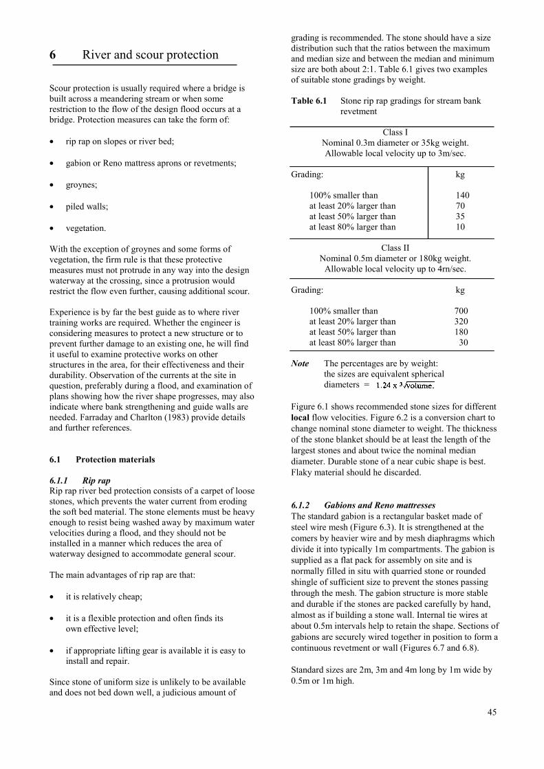
6 River and scour protection
Scour protection is usually required where a bridge isbuilt across a meandering stream or when somerestriction to the flow of the design flood occurs at abridge. Protection measures can take the form of:
• rip rap on slopes or river bed;
• gabion or Reno mattress aprons or revetments;
• groynes;
• piled walls;
• vegetation.
With the exception of groynes and some forms ofvegetation, the firm rule is that these protectivemeasures must not protrude in any way into the designwaterway at the crossing, since a protrusion wouldrestrict the flow even further, causing additional scour.
Experience is by far the best guide as to where rivertraining works are required. Whether the engineer isconsidering measures to protect a new structure or toprevent further damage to an existing one, he will findit useful to examine protective works on otherstructures in the area, for their effectiveness and theirdurability. Observation of the currents at the site inquestion, preferably during a flood, and examination ofplans showing how the river shape progresses, may alsoindicate where bank strengthening and guide walls areneeded. Farraday and Charlton (1983) provide detailsand further references.
6.1 Protection materials
6.1.1 Rip rapRip rap river bed protection consists of a carpet of loosestones, which prevents the water current from erodingthe soft bed material. The stone elements must be heavyenough to resist being washed away by maximum watervelocities during a flood, and they should not beinstalled in a manner which reduces the area ofwaterway designed to accommodate general scour.
The main advantages of rip rap are that:
• it is relatively cheap;
• it is a flexible protection and often finds itsown effective level;
• if appropriate lifting gear is available it is easy toinstall and repair.
Since stone of uniform size is unlikely to be availableand does not bed down well, a judicious amount of
grading is recommended. The stone should have a sizedistribution such that the ratios between the maximumand median size and between the median and minimumsize are both about 2:1. Table 6.1 gives two examplesof suitable stone gradings by weight.
Table 6.1 Stone rip rap gradings for stream bankrevetment
Class INominal 0.3m diameter or 35kg weight.Allowable local velocity up to 3m/sec.
Grading: kg
100% smaller than 140at least 20% larger than 70at least 50% larger than 35at least 80% larger than 10
Class IINominal 0.5m diameter or 180kg weight.
Allowable local velocity up to 4rn/sec.
Grading: kg
100% smaller than 700at least 20% larger than 320at least 50% larger than 180at least 80% larger than 30
Note The percentages are by weight:the sizes are equivalent sphericaldiameters =
Figure 6.1 shows recommended stone sizes for differentlocal flow velocities. Figure 6.2 is a conversion chart tochange nominal stone diameter to weight. The thicknessof the stone blanket should be at least the length of thelargest stones and about twice the nominal mediandiameter. Durable stone of a near cubic shape is best.Flaky material should he discarded.
6.1.2 Gabions and Reno mattressesThe standard gabion is a rectangular basket made ofsteel wire mesh (Figure 6.3). It is strengthened at thecomers by heavier wire and by mesh diaphragms whichdivide it into typically 1m compartments. The gabion issupplied as a flat pack for assembly on site and isnormally filled in situ with quarried stone or roundedshingle of sufficient size to prevent the stones passingthrough the mesh. The gabion structure is more stableand durable if the stones are packed carefully by hand,almost as if building a stone wall. Internal tie wires atabout 0.5m intervals help to retain the shape. Sections ofgabions are securely wired together in position to form acontinuous revetment or wall (Figures 6.7 and 6.8).
Standard sizes are 2m, 3m and 4m long by 1m wide by0.5m or 1m high.
45
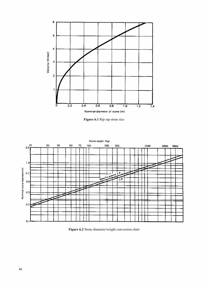
Figure 6.1 Rip rap stone size
Figure 6.2 Stone diameter/weight conversion chart
46
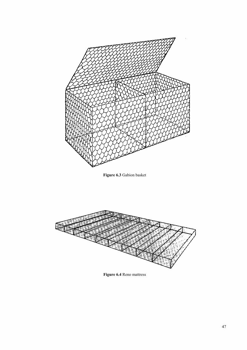
Figure 6.3 Gabion basket
Figure 6.4 Reno mattress
47

Figure 6.5 Timber piled bank protection
48
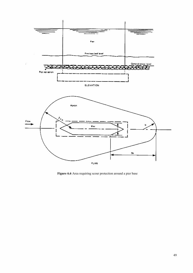
Figure 6.6 Area requiring scour protection around a pier base
49
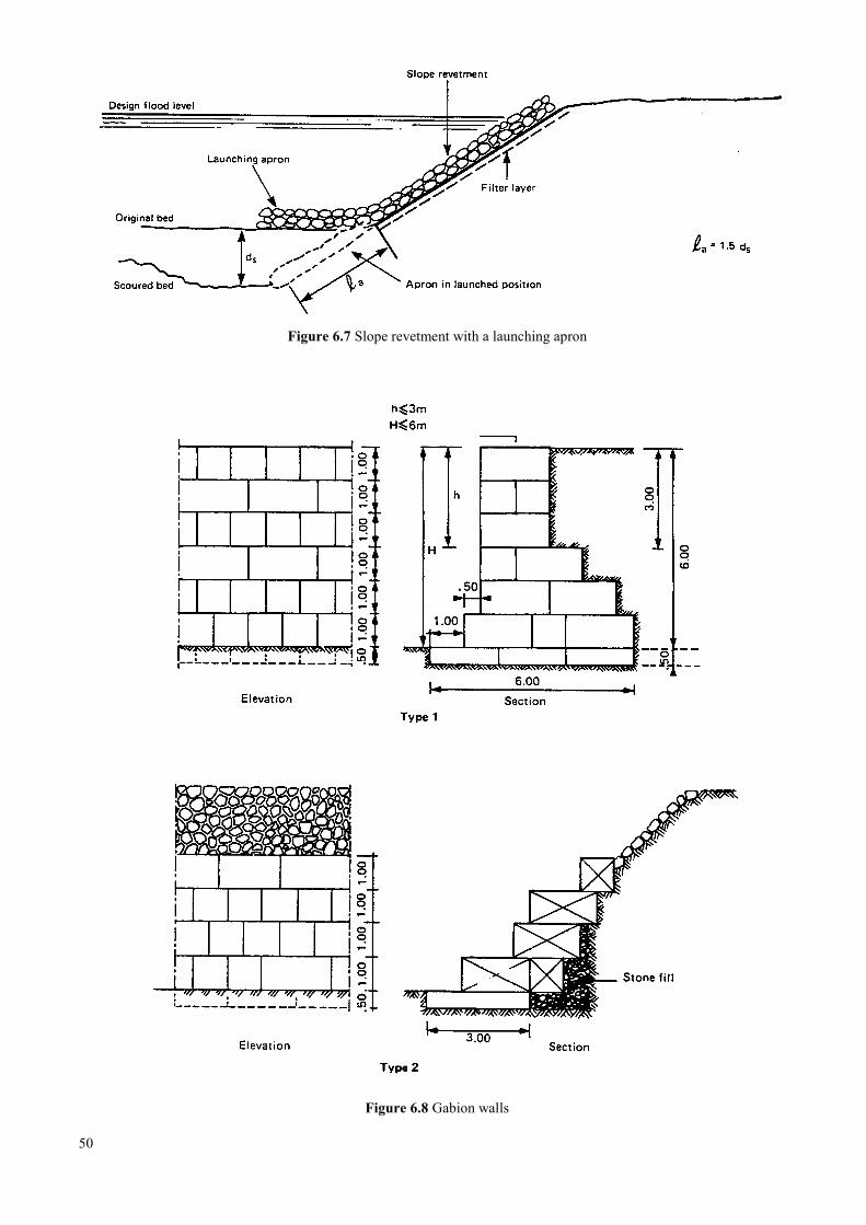
Figure 6.7 Slope revetment with a launching apron
Figure 6.8 Gabion walls
50
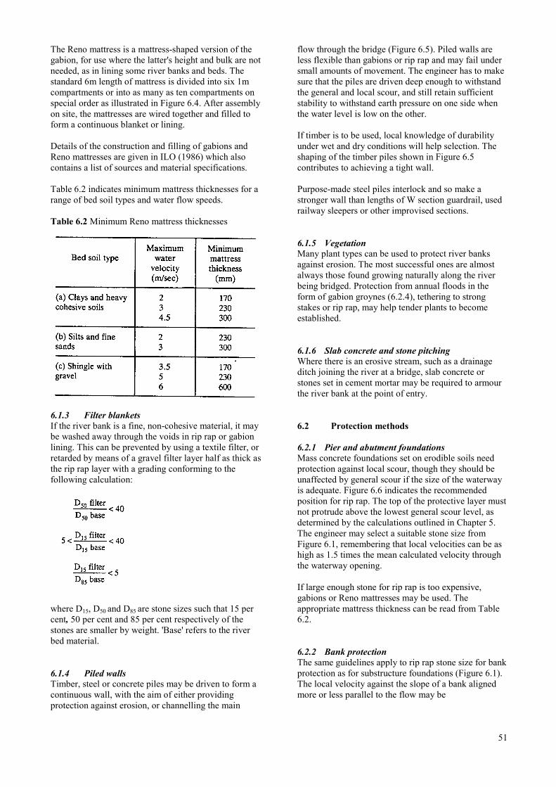
The Reno mattress is a mattress-shaped version of thegabion, for use where the latter's height and bulk are notneeded, as in lining some river banks and beds. Thestandard 6m length of mattress is divided into six 1mcompartments or into as many as ten compartments onspecial order as illustrated in Figure 6.4. After assemblyon site, the mattresses are wired together and filled toform a continuous blanket or lining.
Details of the construction and filling of gabions andReno mattresses are given in ILO (1986) which alsocontains a list of sources and material specifications.
Table 6.2 indicates minimum mattress thicknesses for arange of bed soil types and water flow speeds.
Table 6.2 Minimum Reno mattress thicknesses
6.1.3 Filter blanketsIf the river bank is a fine, non-cohesive material, it maybe washed away through the voids in rip rap or gabionlining. This can be prevented by using a textile filter, orretarded by means of a gravel filter layer half as thick asthe rip rap layer with a grading conforming to thefollowing calculation:
where D15, D50 and D85 are stone sizes such that 15 percent, 50 per cent and 85 per cent respectively of thestones are smaller by weight. 'Base' refers to the riverbed material.
6.1.4 Piled wallsTimber, steel or concrete piles may be driven to form acontinuous wall, with the aim of either providingprotection against erosion, or channelling the main
flow through the bridge (Figure 6.5). Piled walls areless flexible than gabions or rip rap and may fail undersmall amounts of movement. The engineer has to makesure that the piles are driven deep enough to withstandthe general and local scour, and still retain sufficientstability to withstand earth pressure on one side whenthe water level is low on the other.
If timber is to be used, local knowledge of durabilityunder wet and dry conditions will help selection. Theshaping of the timber piles shown in Figure 6.5contributes to achieving a tight wall.
Purpose-made steel piles interlock and so make astronger wall than lengths of W section guardrail, usedrailway sleepers or other improvised sections.
6.1.5 VegetationMany plant types can be used to protect river banksagainst erosion. The most successful ones are almostalways those found growing naturally along the riverbeing bridged. Protection from annual floods in theform of gabion groynes (6.2.4), tethering to strongstakes or rip rap, may help tender plants to becomeestablished.
6.1.6 Slab concrete and stone pitchingWhere there is an erosive stream, such as a drainageditch joining the river at a bridge, slab concrete orstones set in cement mortar may be required to armourthe river bank at the point of entry.
6.2 Protection methods
6.2.1 Pier and abutment foundationsMass concrete foundations set on erodible soils needprotection against local scour, though they should beunaffected by general scour if the size of the waterwayis adequate. Figure 6.6 indicates the recommendedposition for rip rap. The top of the protective layer mustnot protrude above the lowest general scour level, asdetermined by the calculations outlined in Chapter 5.The engineer may select a suitable stone size fromFigure 6.1, remembering that local velocities can be ashigh as 1.5 times the mean calculated velocity throughthe waterway opening.
If large enough stone for rip rap is too expensive,gabions or Reno mattresses may be used. Theappropriate mattress thickness can be read from Table6.2.
6.2.2 Bank protectionThe same guidelines apply to rip rap stone size for bankprotection as for substructure foundations (Figure 6.1).The local velocity against the slope of a bank alignedmore or less parallel to the flow may be
51
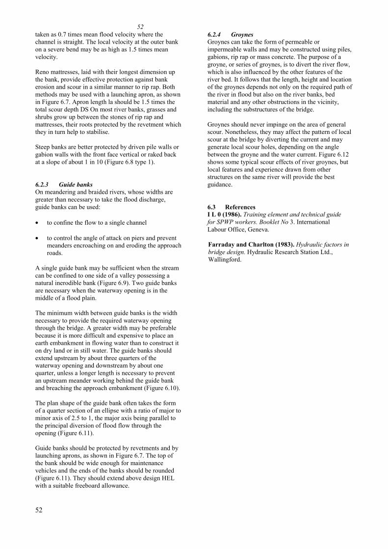
taken as 0.7 times mean flood velocity where thechannel is straight. The local velocity at the outer bankon a severe bend may be as high as 1.5 times meanvelocity.
Reno mattresses, laid with their longest dimension upthe bank, provide effective protection against bankerosion and scour in a similar manner to rip rap. Bothmethods may be used with a launching apron, as shownin Figure 6.7. Apron length la should be 1.5 times thetotal scour depth DS On most river banks, grasses andshrubs grow up between the stones of rip rap andmattresses, their roots protected by the revetment whichthey in turn help to stabilise.
Steep banks are better protected by driven pile walls orgabion walls with the front face vertical or raked backat a slope of about 1 in 10 (Figure 6.8 type 1).
6.2.3 Guide banksOn meandering and braided rivers, whose widths aregreater than necessary to take the flood discharge,guide banks can be used:
• to confine the flow to a single channel
• to control the angle of attack on piers and preventmeanders encroaching on and eroding the approachroads.
A single guide bank may be sufficient when the streamcan be confined to one side of a valley possessing anatural inerodible bank (Figure 6.9). Two guide banksare necessary when the waterway opening is in themiddle of a flood plain.
The minimum width between guide banks is the widthnecessary to provide the required waterway openingthrough the bridge. A greater width may be preferablebecause it is more difficult and expensive to place anearth embankment in flowing water than to construct iton dry land or in still water. The guide banks shouldextend upstream by about three quarters of thewaterway opening and downstream by about onequarter, unless a longer length is necessary to preventan upstream meander working behind the guide bankand breaching the approach embankment (Figure 6.10).
The plan shape of the guide bank often takes the formof a quarter section of an ellipse with a ratio of major tominor axis of 2.5 to 1, the major axis being parallel tothe principal diversion of flood flow through theopening (Figure 6.11).
Guide banks should be protected by revetments and bylaunching aprons, as shown in Figure 6.7. The top ofthe bank should be wide enough for maintenancevehicles and the ends of the banks should be rounded(Figure 6.11). They should extend above design HELwith a suitable freeboard allowance.
52
526.2.4 GroynesGroynes can take the form of permeable orimpermeable walls and may be constructed using piles,gabions, rip rap or mass concrete. The purpose of agroyne, or series of groynes, is to divert the river flow,which is also influenced by the other features of theriver bed. It follows that the length, height and locationof the groynes depends not only on the required path ofthe river in flood but also on the river banks, bedmaterial and any other obstructions in the vicinity,including the substructures of the bridge.
Groynes should never impinge on the area of generalscour. Nonetheless, they may affect the pattern of localscour at the bridge by diverting the current and maygenerate local scour holes, depending on the anglebetween the groyne and the water current. Figure 6.12shows some typical scour effects of river groynes, butlocal features and experience drawn from otherstructures on the same river will provide the bestguidance.
6.3 ReferencesI L 0 (1986). Training element and technical guidefor SPWP workers. Booklet No 3. InternationalLabour Office, Geneva.
Farraday and Charlton (1983). Hydraulic factors inbridge design. Hydraulic Research Station Ltd.,Wallingford.
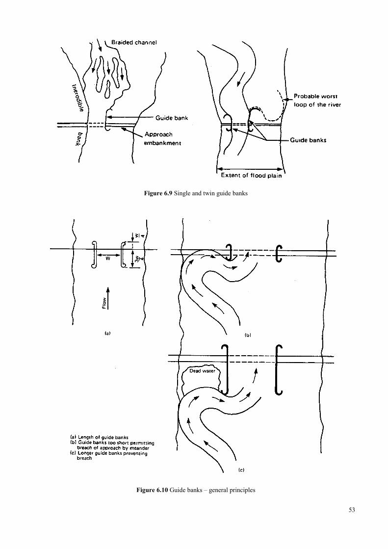
Figure 6.9 Single and twin guide banks
Figure 6.10 Guide banks – general principles
53
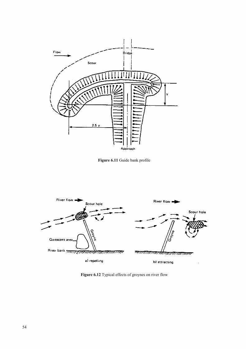
Figure 6.11 Guide bank profile
Figure 6.12 Typical effects of groynes on river flow
54
7 LOW LEVEL WATER CROSSING
7.1 Road approaches ………………………………………………………………………… 57
7.2 Fords …………………………………………………………………………………….. 57
7.2.1 Boulders ………………………………………………………………………. 58
7.2.2 Gabions ……………………………………………………………………….. 58
7.2.3 Piles …………………………………………………………………………... 58
7.3 Bed level causeways ……………………………………………………………………. 60
7.4 Vented causeways ………………………………………………………………………. 61
7.5 Submersible bridges …………………………………………………………………….. 61
7.6 Signs and markers ………………………………………………………………………. 63
7.6.1 Depth gauges …………………………………………………………………. 63
7.6.2 Guide posts …………………………………………………………………… 63
7.7 Designing for maintenance ……………………………………………………………... 64
7.8 References ………………………………………………………………………………. 64
55

56
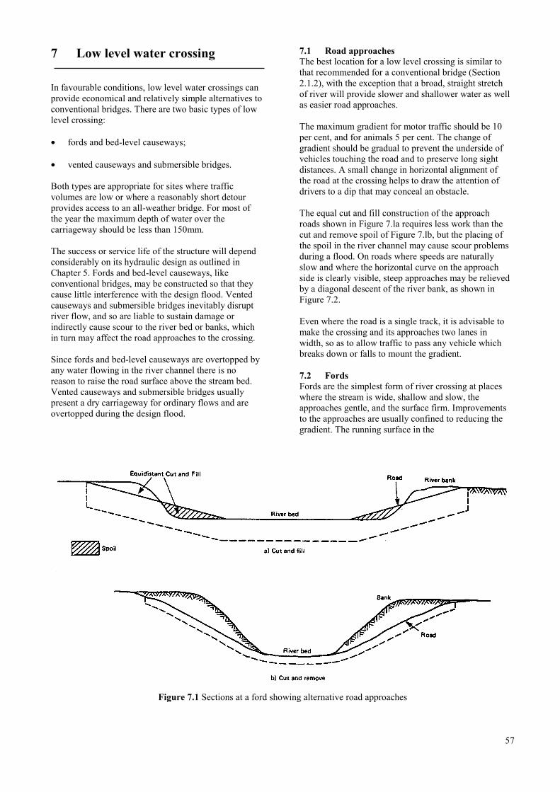
7 Low level water crossing
In favourable conditions, low level water crossings canprovide economical and relatively simple alternatives toconventional bridges. There are two basic types of lowlevel crossing:
• fords and bed-level causeways;
• vented causeways and submersible bridges.
Both types are appropriate for sites where trafficvolumes are low or where a reasonably short detourprovides access to an all-weather bridge. For most ofthe year the maximum depth of water over thecarriageway should be less than 150mm.
The success or service life of the structure will dependconsiderably on its hydraulic design as outlined inChapter 5. Fords and bed-level causeways, likeconventional bridges, may be constructed so that theycause little interference with the design flood. Ventedcauseways and submersible bridges inevitably disruptriver flow, and so are liable to sustain damage orindirectly cause scour to the river bed or banks, whichin turn may affect the road approaches to the crossing.
Since fords and bed-level causeways are overtopped byany water flowing in the river channel there is noreason to raise the road surface above the stream bed.Vented causeways and submersible bridges usuallypresent a dry carriageway for ordinary flows and areovertopped during the design flood.
7.1 Road approachesThe best location for a low level crossing is similar tothat recommended for a conventional bridge (Section2.1.2), with the exception that a broad, straight stretchof river will provide slower and shallower water as wellas easier road approaches.
The maximum gradient for motor traffic should be 10per cent, and for animals 5 per cent. The change ofgradient should be gradual to prevent the underside ofvehicles touching the road and to preserve long sightdistances. A small change in horizontal alignment ofthe road at the crossing helps to draw the attention ofdrivers to a dip that may conceal an obstacle.
The equal cut and fill construction of the approachroads shown in Figure 7.la requires less work than thecut and remove spoil of Figure 7.lb, but the placing ofthe spoil in the river channel may cause scour problemsduring a flood. On roads where speeds are naturallyslow and where the horizontal curve on the approachside is clearly visible, steep approaches may be relievedby a diagonal descent of the river bank, as shown inFigure 7.2.
Even where the road is a single track, it is advisable tomake the crossing and its approaches two lanes inwidth, so as to allow traffic to pass any vehicle whichbreaks down or falls to mount the gradient.
7.2 FordsFords are the simplest form of river crossing at placeswhere the stream is wide, shallow and slow, theapproaches gentle, and the surface firm. Improvementsto the approaches are usually confined to reducing thegradient. The running surface in the
Figure 7.1 Sections at a ford showing alternative road approaches
57
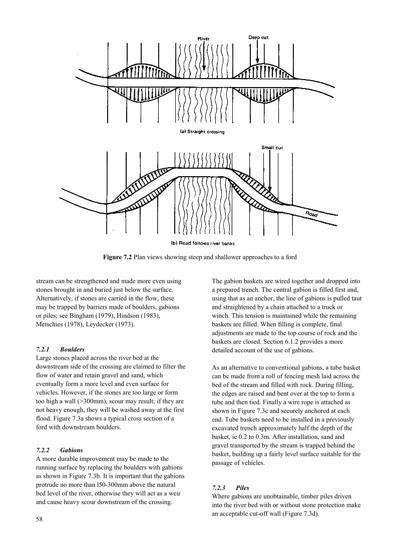
Figure 7.2 Plan views showing steep and shallower approaches to a ford
stream can be strengthened and made more even usingstones brought in and buried just below the surface.Alternatively, if stones are carried in the flow, thesemay be trapped by barriers made of boulders, gabionsor piles; see Bingham (1979), Hindson (1983),Metschies (1978), Leydecker (1973).
7.2.1 BouldersLarge stones placed across the river bed at thedownstream side of the crossing are claimed to filter theflow of water and retain gravel and sand, whicheventually form a more level and even surface forvehicles. However, if the stones are too large or formtoo high a wall (>300mm), scour may result; if they arenot heavy enough, they will be washed away at the firstflood. Figure 7.3a shows a typical cross section of aford with downstream boulders.
7.2.2 GabionsA more durable improvement may be made to therunning surface by replacing the boulders with gabionsas shown in Figure 7.3b. It is important that the gabionsprotrude no more than l50-300mm above the naturalbed level of the river, otherwise they will act as a weirand cause heavy scour downstream of the crossing.
58
The gabion baskets are wired together and dropped intoa prepared trench. The central gabion is filled first and,using that as an anchor, the line of gabions is pulled tautand straightened by a chain attached to a truck orwinch. This tension is maintained while the remainingbaskets are filled. When filling is complete, finaladjustments are made to the top course of rock and thebaskets are closed. Section 6.1.2 provides a moredetailed account of the use of gabions.
As an alternative to conventional gabions, a tube basketcan be made from a roll of fencing mesh laid across thebed of the stream and filled with rock. During filling,the edges are raised and bent over at the top to form atube and then tied. Finally a wire rope is attached asshown in Figure 7.3c and securely anchored at eachend. Tube baskets need to be installed in a previouslyexcavated trench approximately half the depth of thebasket, ie 0.2 to 0.3m. After installation, sand andgravel transported by the stream is trapped behind thebasket, building up a fairly level surface suitable for thepassage of vehicles.
7.2.3 PilesWhere gabions are unobtainable, timber piles driveninto the river bed with or without stone protection makean acceptable cut-off wall (Figure 7.3d).
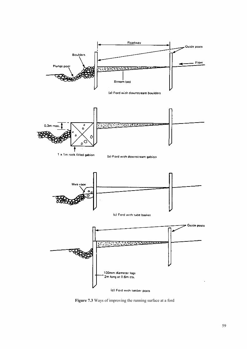
Figure 7.3 Ways of improving the running surface at a ford
59
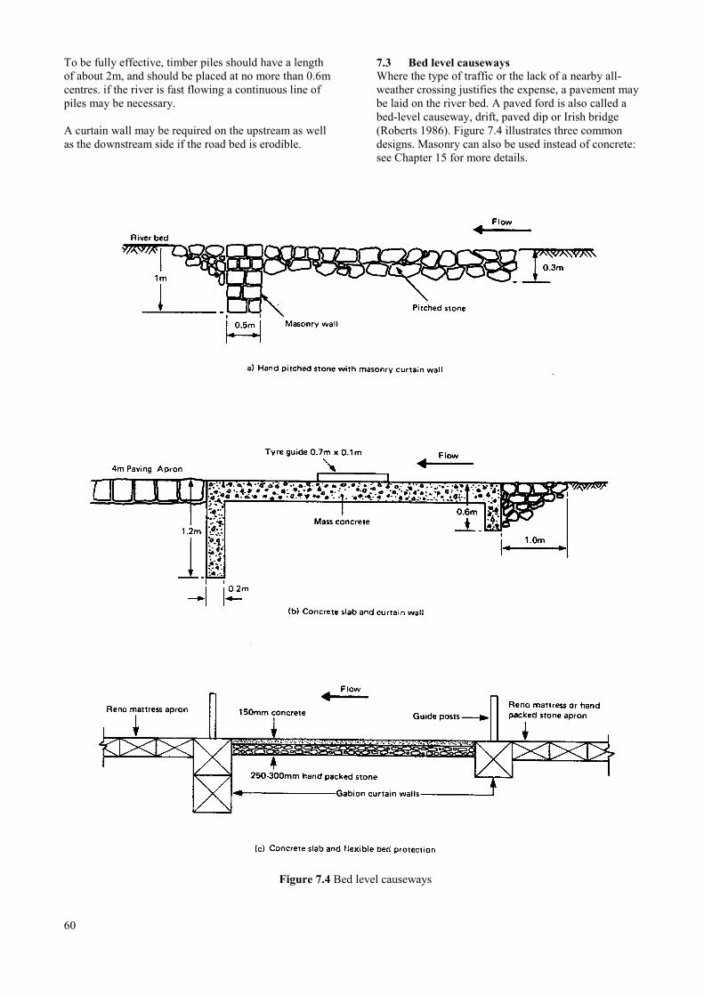
To be fully effective, timber piles should have a lengthof about 2m, and should be placed at no more than 0.6mcentres. if the river is fast flowing a continuous line ofpiles may be necessary.
A curtain wall may be required on the upstream as wellas the downstream side if the road bed is erodible.
7.3 Bed level causewaysWhere the type of traffic or the lack of a nearby all-weather crossing justifies the expense, a pavement maybe laid on the river bed. A paved ford is also called abed-level causeway, drift, paved dip or Irish bridge(Roberts 1986). Figure 7.4 illustrates three commondesigns. Masonry can also be used instead of concrete:see Chapter 15 for more details.
Figure 7.4 Bed level causeways
60
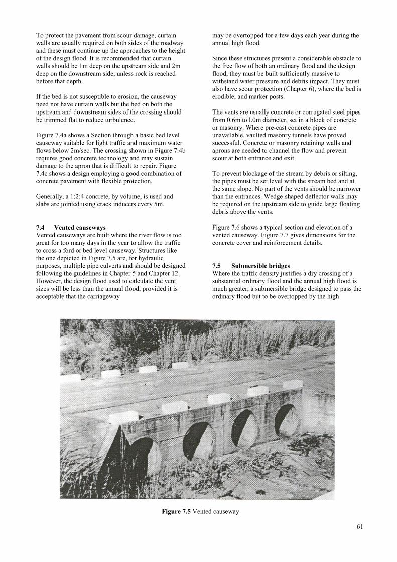
To protect the pavement from scour damage, curtainwalls are usually required on both sides of the roadwayand these must continue up the approaches to the heightof the design flood. It is recommended that curtainwalls should be 1m deep on the upstream side and 2mdeep on the downstream side, unless rock is reachedbefore that depth.
If the bed is not susceptible to erosion, the causewayneed not have curtain walls but the bed on both theupstream and downstream sides of the crossing shouldbe trimmed flat to reduce turbulence.
Figure 7.4a shows a Section through a basic bed levelcauseway suitable for light traffic and maximum waterflows below 2m/sec. The crossing shown in Figure 7.4brequires good concrete technology and may sustaindamage to the apron that is difficult to repair. Figure7.4c shows a design employing a good combination ofconcrete pavement with flexible protection.
Generally, a 1:2:4 concrete, by volume, is used andslabs are jointed using crack inducers every 5m.
7.4 Vented causewaysVented causeways are built where the river flow is toogreat for too many days in the year to allow the trafficto cross a ford or bed level causeway. Structures likethe one depicted in Figure 7.5 are, for hydraulicpurposes, multiple pipe culverts and should be designedfollowing the guidelines in Chapter 5 and Chapter 12.However, the design flood used to calculate the ventsizes will be less than the annual flood, provided it isacceptable that the carriageway
may be overtopped for a few days each year during theannual high flood.
Since these structures present a considerable obstacle tothe free flow of both an ordinary flood and the designflood, they must be built sufficiently massive towithstand water pressure and debris impact. They mustalso have scour protection (Chapter 6), where the bed iserodible, and marker posts.
The vents are usually concrete or corrugated steel pipesfrom 0.6m to l.0m diameter, set in a block of concreteor masonry. Where pre-cast concrete pipes areunavailable, vaulted masonry tunnels have provedsuccessful. Concrete or masonry retaining walls andaprons are needed to channel the flow and preventscour at both entrance and exit.
To prevent blockage of the stream by debris or silting,the pipes must be set level with the stream bed and atthe same slope. No part of the vents should be narrowerthan the entrances. Wedge-shaped deflector walls maybe required on the upstream side to guide large floatingdebris above the vents.
Figure 7.6 shows a typical section and elevation of avented causeway. Figure 7.7 gives dimensions for theconcrete cover and reinforcement details.
7.5 Submersible bridgesWhere the traffic density justifies a dry crossing of asubstantial ordinary flood and the annual high flood ismuch greater, a submersible bridge designed to pass theordinary flood but to be overtopped by the high
Figure 7.5 Vented causeway
61
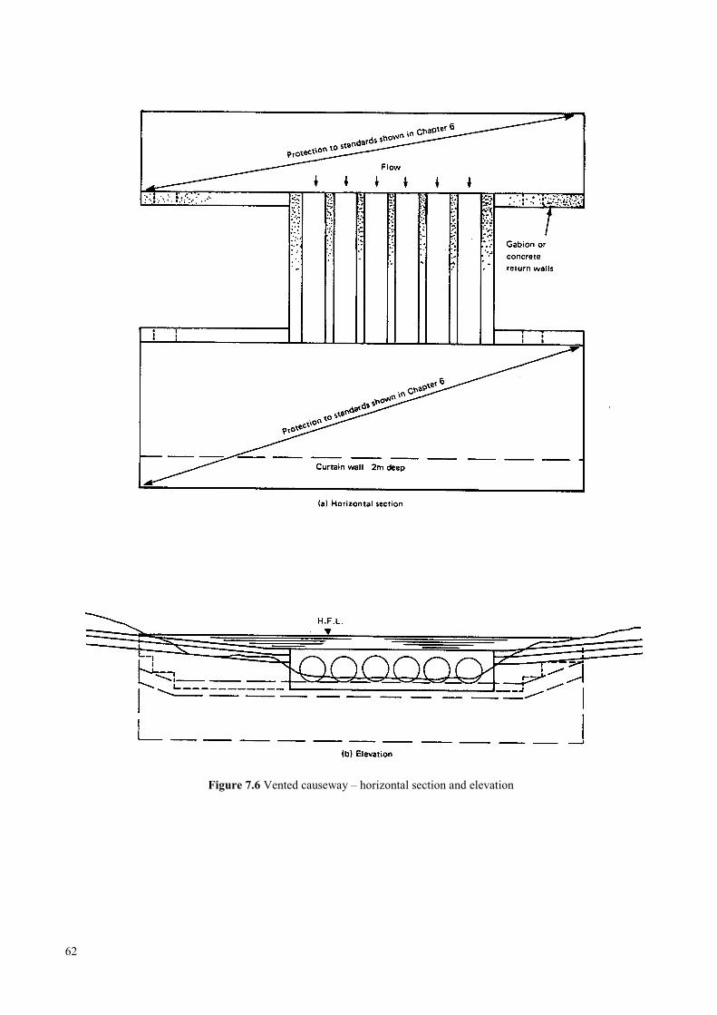
Figure 7.6 Vented causeway – horizontal section and elevation
62
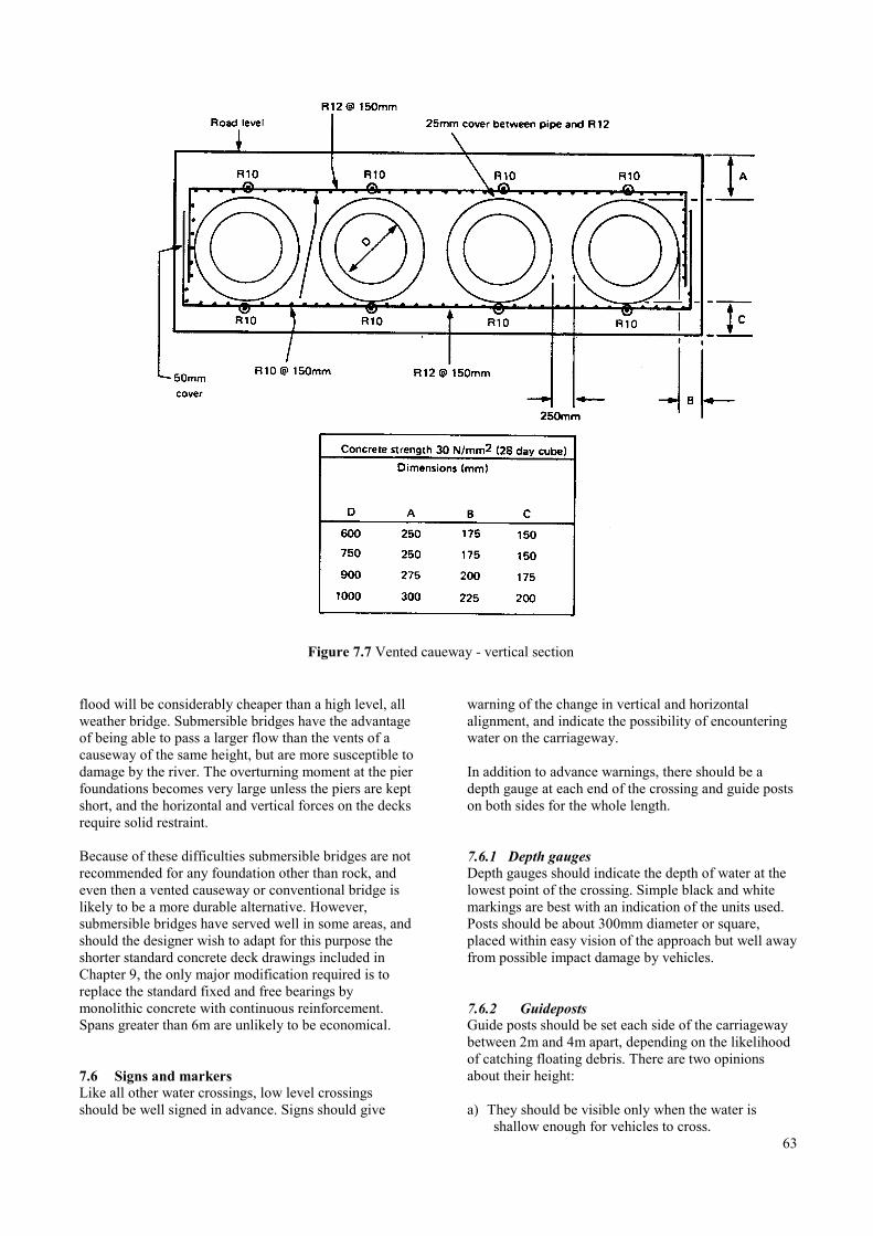
Figure 7.7 Vented caueway - vertical section
flood will be considerably cheaper than a high level, allweather bridge. Submersible bridges have the advantageof being able to pass a larger flow than the vents of acauseway of the same height, but are more susceptible todamage by the river. The overturning moment at the pierfoundations becomes very large unless the piers are keptshort, and the horizontal and vertical forces on the decksrequire solid restraint.
Because of these difficulties submersible bridges are notrecommended for any foundation other than rock, andeven then a vented causeway or conventional bridge islikely to be a more durable alternative. However,submersible bridges have served well in some areas, andshould the designer wish to adapt for this purpose theshorter standard concrete deck drawings included inChapter 9, the only major modification required is toreplace the standard fixed and free bearings bymonolithic concrete with continuous reinforcement.Spans greater than 6m are unlikely to be economical.
7.6 Signs and markersLike all other water crossings, low level crossingsshould be well signed in advance. Signs should give
warning of the change in vertical and horizontalalignment, and indicate the possibility of encounteringwater on the carriageway.
In addition to advance warnings, there should be adepth gauge at each end of the crossing and guide postson both sides for the whole length.
7.6.1 Depth gaugesDepth gauges should indicate the depth of water at thelowest point of the crossing. Simple black and whitemarkings are best with an indication of the units used.Posts should be about 300mm diameter or square,placed within easy vision of the approach but well awayfrom possible impact damage by vehicles.
7.6.2 GuidepostsGuide posts should be set each side of the carriagewaybetween 2m and 4m apart, depending on the likelihoodof catching floating debris. There are two opinionsabout their height:
a) They should be visible only when the water isshallow enough for vehicles to cross.
63
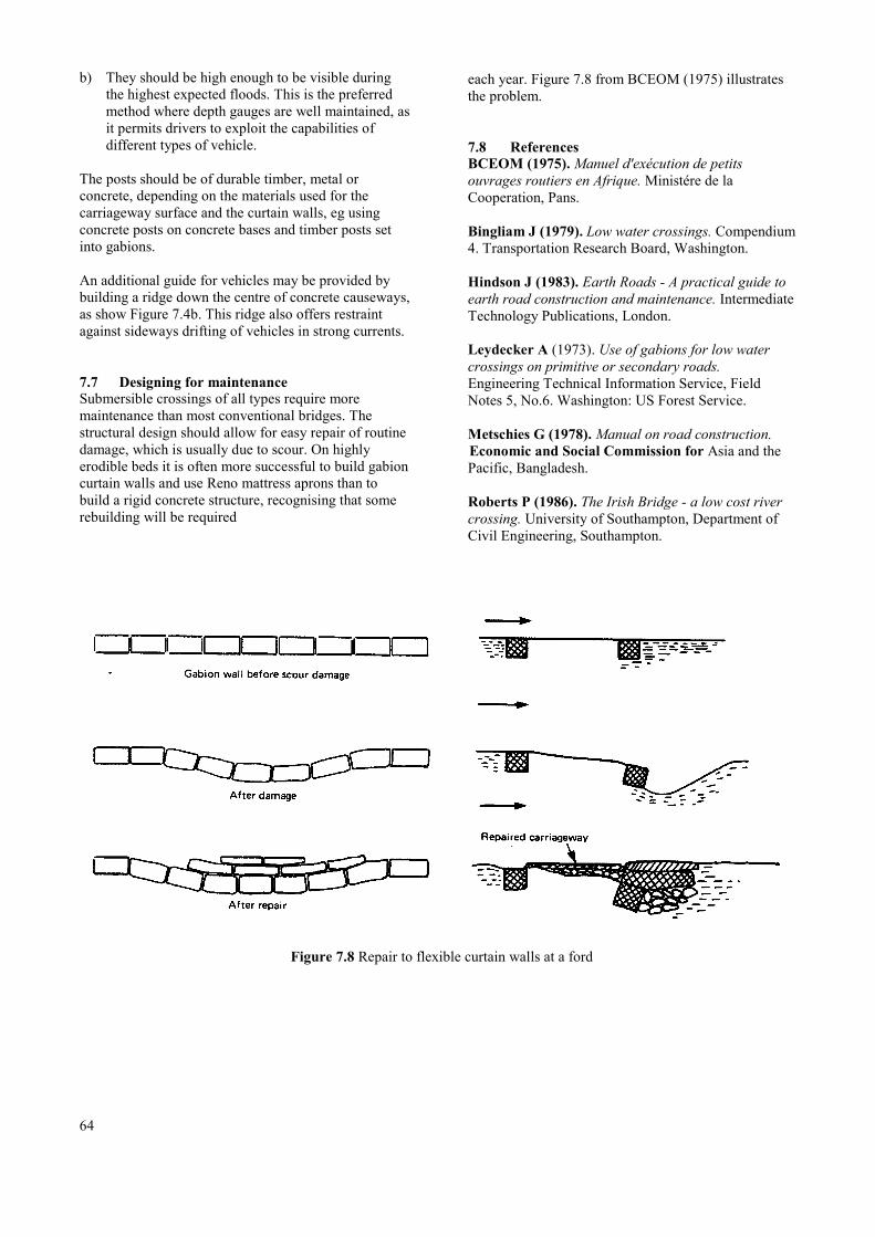
b) They should be high enough to be visible duringthe highest expected floods. This is the preferredmethod where depth gauges are well maintained, asit permits drivers to exploit the capabilities ofdifferent types of vehicle.
The posts should be of durable timber, metal orconcrete, depending on the materials used for thecarriageway surface and the curtain walls, eg usingconcrete posts on concrete bases and timber posts setinto gabions.
An additional guide for vehicles may be provided bybuilding a ridge down the centre of concrete causeways,as show Figure 7.4b. This ridge also offers restraintagainst sideways drifting of vehicles in strong currents.
7.7 Designing for maintenanceSubmersible crossings of all types require moremaintenance than most conventional bridges. Thestructural design should allow for easy repair of routinedamage, which is usually due to scour. On highlyerodible beds it is often more successful to build gabioncurtain walls and use Reno mattress aprons than tobuild a rigid concrete structure, recognising that somerebuilding will be required
each year. Figure 7.8 from BCEOM (1975) illustratesthe problem.
7.8 ReferencesBCEOM (1975). Manuel d'exécution de petitsouvrages routiers en Afrique. Ministére de laCooperation, Pans.
Bingliam J (1979). Low water crossings. Compendium4. Transportation Research Board, Washington.
Hindson J (1983). Earth Roads - A practical guide toearth road construction and maintenance. IntermediateTechnology Publications, London.
Leydecker A (1973). Use of gabions for low watercrossings on primitive or secondary roads.Engineering Technical Information Service, FieldNotes 5, No.6. Washington: US Forest Service.
Metschies G (1978). Manual on road construction.Economic and Social Commission for Asia and thePacific, Bangladesh.
Roberts P (1986). The Irish Bridge - a low cost rivercrossing. University of Southampton, Department ofCivil Engineering, Southampton.
Figure 7.8 Repair to flexible curtain walls at a ford
64
8 SUBSTRUCTURES AND FOUNDATIONS
8.1 Abutments …………………………………………………………………………………... 68
8.2 Piers ………………………………………………………………………………………… 68
8.3 Determination of allowable bearing pressure ………………………………………………. 68
8.3.1 Non-cohesive soils ………………………………………………………………... 68
8.3.2 Cohesive soils …………………………………………………………………….. 70
8.3.3 Plate bearing tests ………………………………………………………………… 71
8.3.4 Presumed values ………………………………………………………………….. 73
8.4 Abutment design ……………………………………………………………………………. 73
8.4.1 Mass concrete abutments …………………………………………………………. 73
8.4.2 Mass concrete retaining walls …………………………………………………….. 73
8.4.3 Reinforced concrete abutments …………………………………………………... 74
8.4.4 Reinforced concrete retaining walls ……………………………………………… 74
8.4.5 Raft foundations ………………………………………………………………….. 74
8.4.6 Bearing shelves …………………………………………………………………... 74
8.5 Reinforced concrete piers …………………………………………………………………... 74
8.6 Foundations on rock ………………………………………………………………………… 74
8.7 Earthquake restraint ………………………………………………………………………… 74
8.8 Run-on slabs ………………………………………………………………………………... 75
8.9 References ………………………………………………………………………………….. 75
8.10 Standard drawings and tables for abutments, retaining walls and piers ……………………. 76
8.10.1 Index of drawings ………………………………………………………………… 76
8.10.2 Index of tables …………………………………………………………………... 100
Appendix A8.1 ………………………………………………………………………………………. 114
65

66
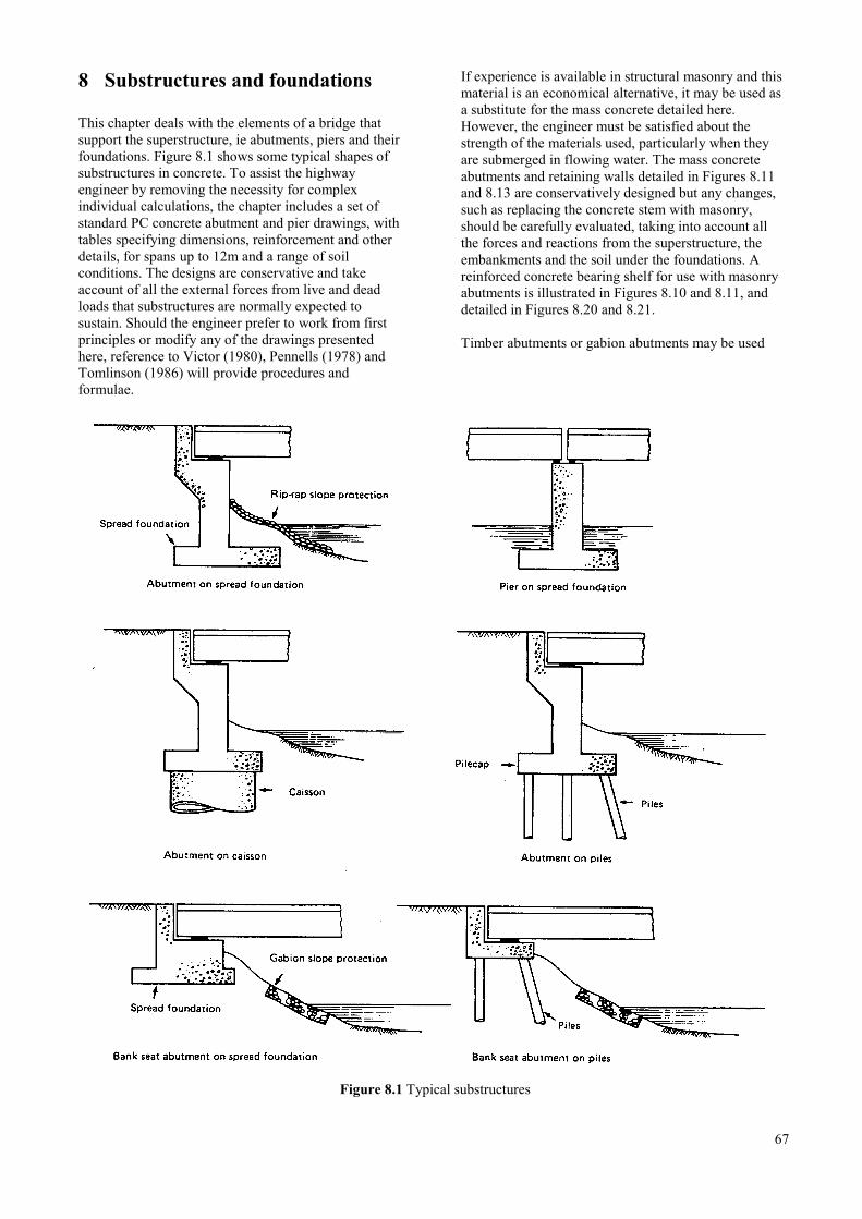
8 Substructures and foundations
This chapter deals with the elements of a bridge thatsupport the superstructure, ie abutments, piers and theirfoundations. Figure 8.1 shows some typical shapes ofsubstructures in concrete. To assist the highwayengineer by removing the necessity for complexindividual calculations, the chapter includes a set ofstandard PC concrete abutment and pier drawings, withtables specifying dimensions, reinforcement and otherdetails, for spans up to 12m and a range of soilconditions. The designs are conservative and takeaccount of all the external forces from live and deadloads that substructures are normally expected tosustain. Should the engineer prefer to work from firstprinciples or modify any of the drawings presentedhere, reference to Victor (1980), Pennells (1978) andTomlinson (1986) will provide procedures andformulae.
If experience is available in structural masonry and thismaterial is an economical alternative, it may be used asa substitute for the mass concrete detailed here.However, the engineer must be satisfied about thestrength of the materials used, particularly when theyare submerged in flowing water. The mass concreteabutments and retaining walls detailed in Figures 8.11and 8.13 are conservatively designed but any changes,such as replacing the concrete stem with masonry,should be carefully evaluated, taking into account allthe forces and reactions from the superstructure, theembankments and the soil under the foundations. Areinforced concrete bearing shelf for use with masonryabutments is illustrated in Figures 8.10 and 8.11, anddetailed in Figures 8.20 and 8.21.
Timber abutments or gabion abutments may be used
Figure 8.1 Typical substructures
67
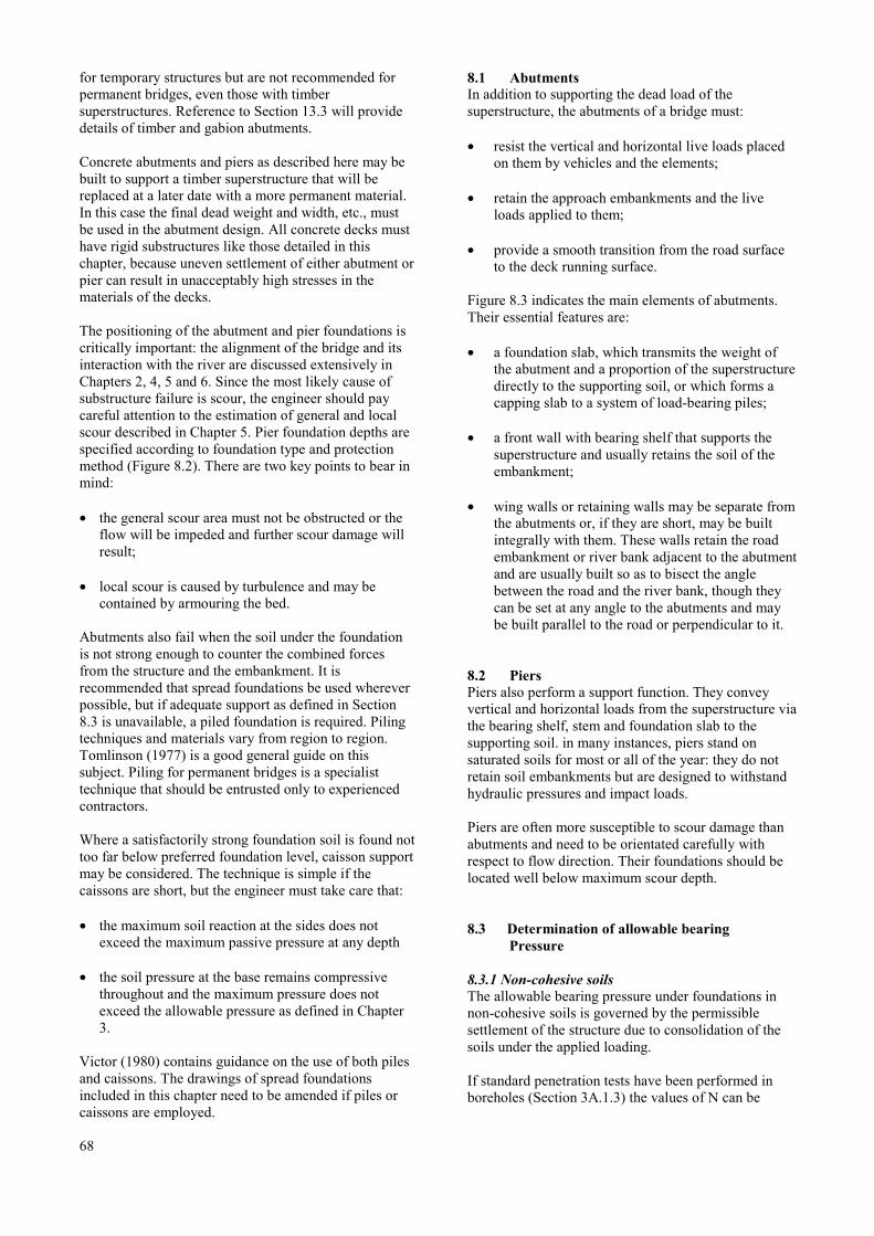
for temporary structures but are not recommended forpermanent bridges, even those with timbersuperstructures. Reference to Section 13.3 will providedetails of timber and gabion abutments.
Concrete abutments and piers as described here may bebuilt to support a timber superstructure that will bereplaced at a later date with a more permanent material.In this case the final dead weight and width, etc., mustbe used in the abutment design. All concrete decks musthave rigid substructures like those detailed in thischapter, because uneven settlement of either abutment orpier can result in unacceptably high stresses in thematerials of the decks.
The positioning of the abutment and pier foundations iscritically important: the alignment of the bridge and itsinteraction with the river are discussed extensively inChapters 2, 4, 5 and 6. Since the most likely cause ofsubstructure failure is scour, the engineer should paycareful attention to the estimation of general and localscour described in Chapter 5. Pier foundation depths arespecified according to foundation type and protectionmethod (Figure 8.2). There are two key points to bear inmind:
• the general scour area must not be obstructed or theflow will be impeded and further scour damage willresult;
• local scour is caused by turbulence and may becontained by armouring the bed.
Abutments also fail when the soil under the foundationis not strong enough to counter the combined forcesfrom the structure and the embankment. It isrecommended that spread foundations be used whereverpossible, but if adequate support as defined in Section8.3 is unavailable, a piled foundation is required. Pilingtechniques and materials vary from region to region.Tomlinson (1977) is a good general guide on thissubject. Piling for permanent bridges is a specialisttechnique that should be entrusted only to experiencedcontractors.
Where a satisfactorily strong foundation soil is found nottoo far below preferred foundation level, caisson supportmay be considered. The technique is simple if thecaissons are short, but the engineer must take care that:
• the maximum soil reaction at the sides does notexceed the maximum passive pressure at any depth
• the soil pressure at the base remains compressivethroughout and the maximum pressure does notexceed the allowable pressure as defined in Chapter3.
Victor (1980) contains guidance on the use of both pilesand caissons. The drawings of spread foundationsincluded in this chapter need to be amended if piles orcaissons are employed.
68
8.1 AbutmentsIn addition to supporting the dead load of thesuperstructure, the abutments of a bridge must:
• resist the vertical and horizontal live loads placedon them by vehicles and the elements;
• retain the approach embankments and the liveloads applied to them;
• provide a smooth transition from the road surfaceto the deck running surface.
Figure 8.3 indicates the main elements of abutments.Their essential features are:
• a foundation slab, which transmits the weight ofthe abutment and a proportion of the superstructuredirectly to the supporting soil, or which forms acapping slab to a system of load-bearing piles;
• a front wall with bearing shelf that supports thesuperstructure and usually retains the soil of theembankment;
• wing walls or retaining walls may be separate fromthe abutments or, if they are short, may be builtintegrally with them. These walls retain the roadembankment or river bank adjacent to the abutmentand are usually built so as to bisect the anglebetween the road and the river bank, though theycan be set at any angle to the abutments and maybe built parallel to the road or perpendicular to it.
8.2 PiersPiers also perform a support function. They conveyvertical and horizontal loads from the superstructure viathe bearing shelf, stem and foundation slab to thesupporting soil. in many instances, piers stand onsaturated soils for most or all of the year: they do notretain soil embankments but are designed to withstandhydraulic pressures and impact loads.
Piers are often more susceptible to scour damage thanabutments and need to be orientated carefully withrespect to flow direction. Their foundations should belocated well below maximum scour depth.
8.3 Determination of allowable bearingPressure
8.3.1 Non-cohesive soilsThe allowable bearing pressure under foundations innon-cohesive soils is governed by the permissiblesettlement of the structure due to consolidation of thesoils under the applied loading.
If standard penetration tests have been performed inboreholes (Section 3A.1.3) the values of N can be
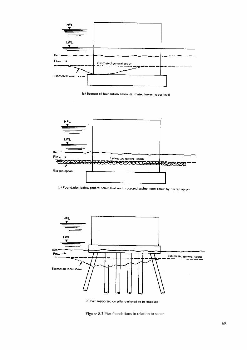
Figure 8.2 Pier foundations in relation to scour
69
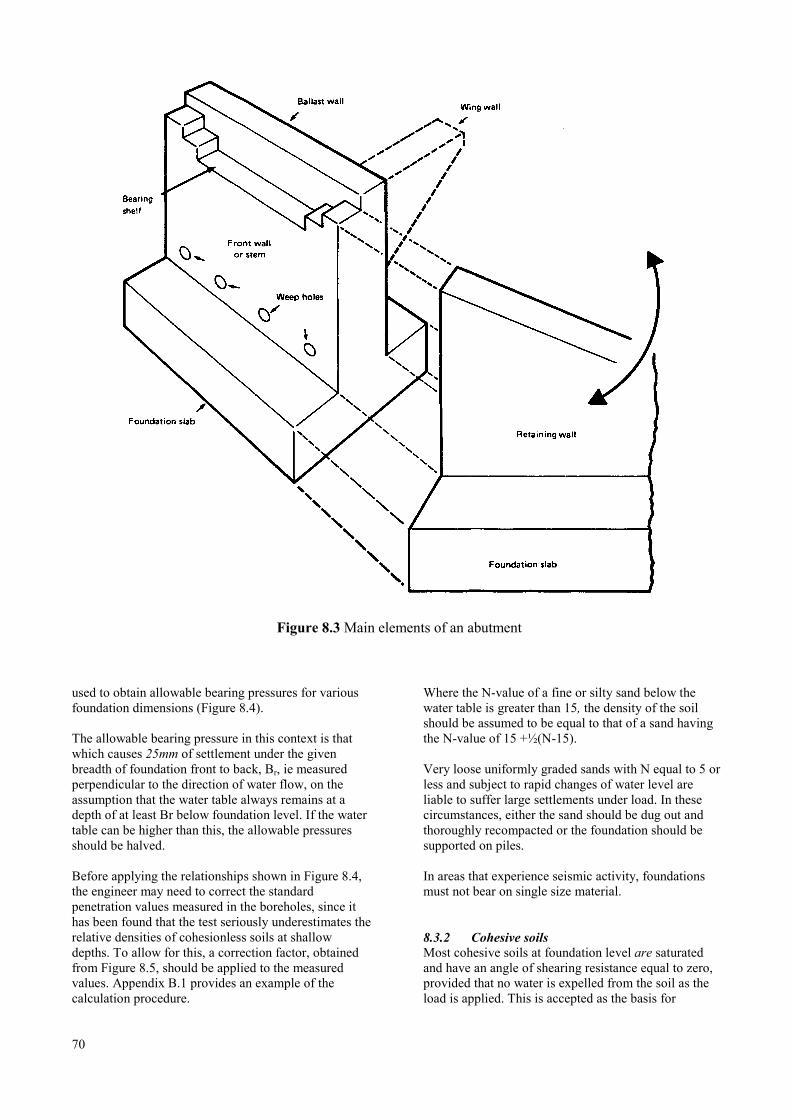
Figure 8.3 Main elements of an abutment
used to obtain allowable bearing pressures for variousfoundation dimensions (Figure 8.4).
The allowable bearing pressure in this context is thatwhich causes 25mm of settlement under the givenbreadth of foundation front to back, Br, ie measuredperpendicular to the direction of water flow, on theassumption that the water table always remains at adepth of at least Br below foundation level. If the watertable can be higher than this, the allowable pressuresshould be halved.
Before applying the relationships shown in Figure 8.4,the engineer may need to correct the standardpenetration values measured in the boreholes, since ithas been found that the test seriously underestimates therelative densities of cohesionless soils at shallowdepths. To allow for this, a correction factor, obtainedfrom Figure 8.5, should be applied to the measuredvalues. Appendix B.1 provides an example of thecalculation procedure.
70
Where the N-value of a fine or silty sand below thewater table is greater than 15, the density of the soilshould be assumed to be equal to that of a sand havingthe N-value of 15 +½(N-15).
Very loose uniformly graded sands with N equal to 5 orless and subject to rapid changes of water level areliable to suffer large settlements under load. In thesecircumstances, either the sand should be dug out andthoroughly recompacted or the foundation should besupported on piles.
In areas that experience seismic activity, foundationsmust not bear on single size material.
8.3.2 Cohesive soilsMost cohesive soils at foundation level are saturatedand have an angle of shearing resistance equal to zero,provided that no water is expelled from the soil as theload is applied. This is accepted as the basis for
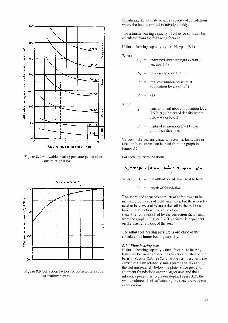
Figure 8.4 Allowable bearing pressure/penetrationvalue relationships
Figure 8.5 Correction factors for cohesionless soilsat shallow depths
calculating the ultimate bearing capacity of foundationswhere the load is applied relatively quickly.
The ultimate bearing capacity of cohesive soils can becalculated from the following formula:
Ultimate bearing capacity qf = cu Nc +p (8.1)
WhereCu = undrained shear strength (kN/m2)
(section 3.4)
Nc = bearing capacity factor
P = total overburden pressure atFoundation level (kN/m2)
P = γ.D
whereg = density of soil above foundation level
(kN/m³) (submerged density wherebelow water level)
D = depth of foundation level belowground surface (m).
Values of the bearing capacity factor Nc for square orcircular foundations can be read from the graph inFigure 8.6.
For rectangular foundations
Where: Br = breadth of foundation front to back
L = length of foundation
The undrained shear strength, cu of soft clays can bemeasured by means of field vane tests, but these resultsneed to be corrected because the soil is sheared in ahorizontal direction. The value of ca, toshear strength multiplied by the correction factor readfrom the graph in Figure 8.7. This factor is dependenton the plasticity index of the soil.
The allowable bearing pressure is one-third of thecalculated ultimate bearing capacity.
8.3.3 Plate bearing testsUltimate bearing capacity values from plate bearingtests may be used to check the results calculated on thebasis of Section 8.3.1 or 8.3.2. However, these tests arecarried out with relatively small plates and stress onlythe soil immediately below the plate. Since pier andabutment foundations cover a larger area and theirinfluence penetrates to greater depths Figure 3.2), thewhole volume of soil affected by the structure requiresexamination.
71
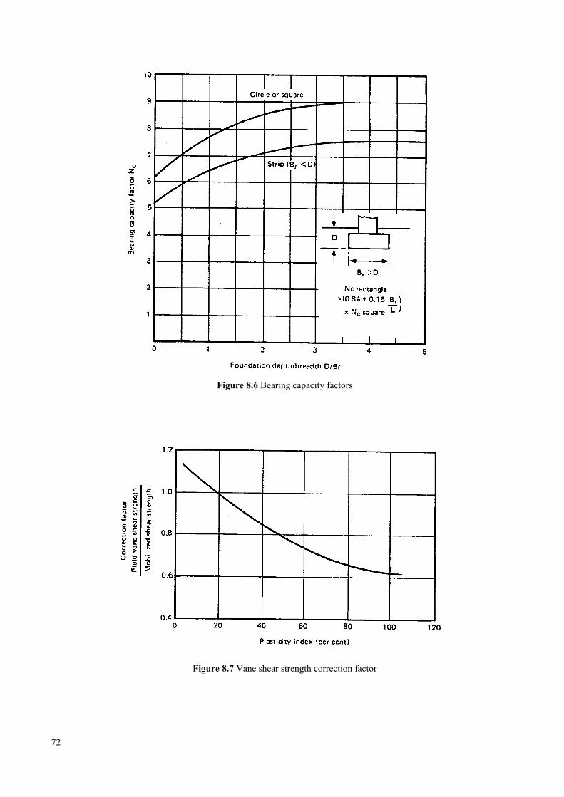
Figure 8.6 Bearing capacity factors
Figure 8.7 Vane shear strength correction factor
72
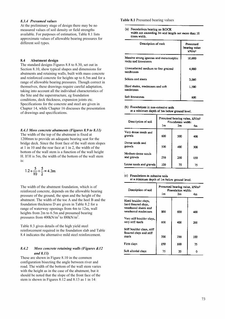
8.3.4 Presumed valuesAt the preliminary stage of design there may be nomeasured values of soil density or field strengthsavailable. For purposes of estimation, Table 8.1 listsapproximate values of allowable bearing pressures fordifferent soil types.
8.4 Abutment designThe standard designs Figures 8.8 to 8.30, set out inSection 8.10, show typical shapes and dimensions forabutments and retaining walls, built with mass concreteand reinforced concrete for heights up to 6.5m and for arange of allowable bearing pressures. Though correct inthemselves, these drawings require careful adaptation,taking into account all the individual characteristics ofthe Site and the superstructure, eg foundationconditions, deck thickness, expansion joints etc.Specifications for the concrete and steel are given inChapter 14, while Chapter 16 discusses the presentationof drawings and specifications.
8.4.1 Moss concrete abutments (Figures 8.9 to 8.11)The width of the top of the abutment is fixed at1200mm to provide an adequate bearing seat for thebridge deck. Since the front face of the wall stem slopesat 1 in 10 and the rear face at 1 in 2, the width of thebottom of the wall stem is a function of the wall heightH. If H is 5m, the width of the bottom of the wall stemis:
The width of the abutment foundation, which is ofreinforced concrete, depends on the allowable bearingpressure of the ground, the span and the height of theabutment. The width of the toe A and the heel B and thefoundation thickness D are given in Table 8.2 for arange of waterway openings from 4m to 12m, wallheights from 2m to 6.5m and presumed bearingpressures from 400kN/m2 to l00kN/m2.
Table 8.3 gives details of the high yield steelreinforcement required in the foundation slab and Table8.4 indicates the alternative mild steel reinforcement.
8.4.2 Moss concrete retaining walls (Figures &12and 8.13)
These are shown in Figure 8.10 in the commonconfiguration bisecting the angle between river androad. The width of the bottom of the wall stem varieswith the height as in the case of the abutment, but itshould be noted that the slope of the front face of thestem is shown in Figures 8.12 and 8.13 as 1 in 14:
Table 8.1 Presumed bearing values
73
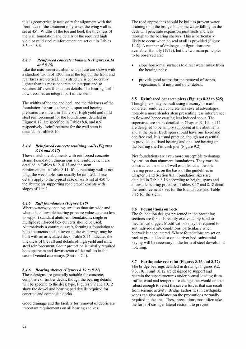
this is geometrically necessary for alignment with thefront face of the abutment only when the wing wall isset at 45º . Widths of the toe and heel, the thickness ofthe wall foundation and details of the required highyield or mild steel reinforcement are set out in Tables8.5 and 8.6.
8.4.3 Reinforced concrete abutments (Figures 8.14and 8.15)
Like the mass concrete abutments, these are shown witha standard width of 1200mm at the top but the front andrear faces are vertical. This structure is considerablylighter than its mass concrete counterpart and sorequires different foundation details. The bearing shelfnow becomes an integral part of the stem.
The widths of the toe and heel, and the thickness of thefoundation for various heights, span and bearingpressures are shown in Table 8.7. High yield and mildsteel reinforcement for the foundations, detailed inFigure 8.17, are specified in Tables 8.8, and 8.9respectively. Reinforcement for the wall stem isdetailed in Table 8.10.
8.4.4 Reinforced concrete retaining walls (Figures&16 and &17)
These match the abutments with reinforced concretestems. Foundation dimensions and reinforcement aredetailed in Tables 8.12, 8.13 and the stemreinforcement in Table 8.11. If the retaining wall is notlong, the weep holes can usually be omitted. Thesedetails apply to the typical case of walls set at 450 tothe abutments supporting road embankments withslopes of 1 in 2.
8.4.5 Raft foundations (Figure 8.18)Where waterway openings are less than 4m wide andwhere the allowable bearing pressure values are too lowto support standard abutment foundations, single ormultiple reinforced box culverts should be used.Alternatively a continuous raft, forming a foundation toboth abutments and an invert to the waterway, may bebuilt with an articulated deck. Table 8.14 indicates thethickness of the raft and details of high yield and mildsteel reinforcement. Scour protection is usually requiredboth upstream and downstream of the raft, as in thecase of vented causeways (Section 7.4).
8.4.6 Bearing shelves (Figures 8.19 to 8.21)These designs are generally suitable for concrete,composite or timber decks, though the bearing detailswill be specific to the deck type. Figures 9.2 and 10.12show the dowel and bearing pad details required forconcrete and composite decks.
Good drainage and the facility for removal of debris areimportant requirements on all bearing shelves.
74
The road approaches should be built to prevent waterdraining onto the bridge, but some water falling on thedeck will penetrate expansion joint seals and leakthrough to the bearing shelves. This is particularlylikely to occur when no seal at all is provided (Figure14.2). A number of drainage configurations areavailable, Hambly (1979), but the two main principlesto be observed are:
• slope horizontal surfaces to direct water away fromthe bearing pads;
• provide good access for the removal of stones,vegetation, bird nests and other debris.
8.5 Reinforced concrete piers (Figures 8.22 to 825)Though piers may be built using masonry or massconcrete, reinforced concrete has several advantages,notably a more slender stem presenting less interferenceto flow and hence causing less induced scour. Thesuperstructure spans detailed in Chapters 9, 10 and 11are designed to be simply supported at the abutmentsand at the piers. Bach span should have one fixed andone free end. It is usual practice, though not essential,to provide one fixed bearing and one free bearing onthe bearing shelf of each pier (Figure 9.2).
Pier foundations are even more susceptible to damageby erosion than abutment foundations. They must beconstructed on soils of well established allowablebearing pressure, on the basis of the guidelines inChapter 3 and Section 8.3. Foundation sizes aredetailed in Table 8.16 according to height, spans andallowable bearing pressures. Tables 8.17 and 8.18 detailthe reinforcement sizes for the foundations and Table8.15 for the stem.
8.6 Foundations on rockThe foundation designs presented in the precedingsections are for soils readily excavated by hand ormechanical digger. Modifications may be required tosuit individual site conditions, particularly whenbedrock is encountered. Where foundations are set onrock at ground level or on the river bed, substantialkeying will be necessary in the form of steel dowels andnotching.
8.7 Earthquake restraint (Figures 8.26 and 8.27)The bridge bearings detailed in drawings Figures 9.2,9.3, 10.11 and 10.12 are designed to support andrestrain the superstructures under normal loading fromtraffic, wind and temperature change, but would not berobust enough to resist the severe forces that can resultfrom seismic activity. Bridge authorities in earthquakezones can give guidance on the precautions normallyrequired in the area. These precautions most often takethe form of stronger lateral restraint to prevent
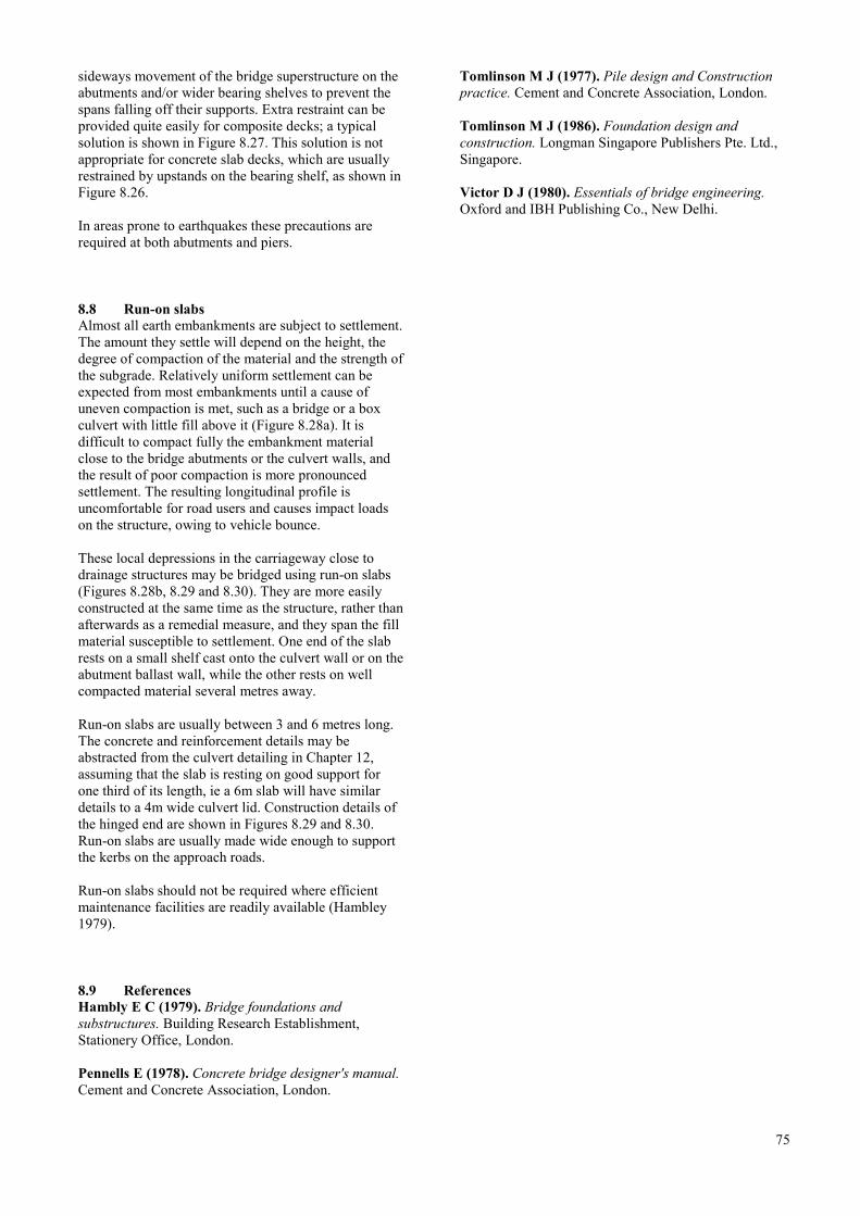
sideways movement of the bridge superstructure on theabutments and/or wider bearing shelves to prevent thespans falling off their supports. Extra restraint can beprovided quite easily for composite decks; a typicalsolution is shown in Figure 8.27. This solution is notappropriate for concrete slab decks, which are usuallyrestrained by upstands on the bearing shelf, as shown inFigure 8.26.
In areas prone to earthquakes these precautions arerequired at both abutments and piers.
8.8 Run-on slabsAlmost all earth embankments are subject to settlement.The amount they settle will depend on the height, thedegree of compaction of the material and the strength ofthe subgrade. Relatively uniform settlement can beexpected from most embankments until a cause ofuneven compaction is met, such as a bridge or a boxculvert with little fill above it (Figure 8.28a). It isdifficult to compact fully the embankment materialclose to the bridge abutments or the culvert walls, andthe result of poor compaction is more pronouncedsettlement. The resulting longitudinal profile isuncomfortable for road users and causes impact loadson the structure, owing to vehicle bounce.
These local depressions in the carriageway close todrainage structures may be bridged using run-on slabs(Figures 8.28b, 8.29 and 8.30). They are more easilyconstructed at the same time as the structure, rather thanafterwards as a remedial measure, and they span the fillmaterial susceptible to settlement. One end of the slabrests on a small shelf cast onto the culvert wall or on theabutment ballast wall, while the other rests on wellcompacted material several metres away.
Run-on slabs are usually between 3 and 6 metres long.The concrete and reinforcement details may beabstracted from the culvert detailing in Chapter 12,assuming that the slab is resting on good support forone third of its length, ie a 6m slab will have similardetails to a 4m wide culvert lid. Construction details ofthe hinged end are shown in Figures 8.29 and 8.30.Run-on slabs are usually made wide enough to supportthe kerbs on the approach roads.
Run-on slabs should not be required where efficientmaintenance facilities are readily available (Hambley1979).
8.9 ReferencesHambly E C (1979). Bridge foundations andsubstructures. Building Research Establishment,Stationery Office, London.
Pennells E (1978). Concrete bridge designer's manual.Cement and Concrete Association, London.
Tomlinson M J (1977). Pile design and Constructionpractice. Cement and Concrete Association, London.
Tomlinson M J (1986). Foundation design andconstruction. Longman Singapore Publishers Pte. Ltd.,Singapore.
Victor D J (1980). Essentials of bridge engineering.Oxford and IBH Publishing Co., New Delhi.
75
8.10 Standard drawings and tables for abutments, retaining walls and piers8.10.1 Index of drawings
Title Figure number
Typical elevation of a single span bridge …………………………………………………………………………….. 8.8
Abutment - front elevation ……………………………………………………………………………………………. 8.9
Abutment - plan ……………………………………………………………………………………………………... 8.10
Abutment, mass concrete - vertical section ………………………………………………………………………….. 8.11
Retaining wall, mass concrete - plan and elevation …………………………………………………………………. 8.12
Retaining wall, mass concrete - vertical section …………………………………………………………………….. 8.13
Abutment, reinforced concrete - vertical section ……………………………………………………………………. 8.14
Abutment, reinforced concrete - side elevation ………………………………………………………………………8.15
Retaining wall, reinforced concrete - plan and elevation ……………………………………………………………. 8.16
Retaining wall, reinforced concrete - vertical section ……………………………………………………………….. 8.17
Raft foundation ………………………………………………………………………………………………………. 8.18
Bearing shelf - front elevation………………………………………………………………………………………... 8.19
Bearing shelf - details ……………………………………………………………………………………………….. 8.20
Bearing shelf - reinforcement ………………………………………………………………………………………... 8.21
Piers - general arrangement ………………………………………………………………………………………….. 8.22
Pier - plan and elevation ……………………………………………………………………………………………... 8.23
Pier - vertical section ………………………………………………………………………………………………… 8.24
Pier - horizontal section ………………………………………………………………………………………………8.25
Earthquake restraint - concrete superstructure ………………………………………………………………………. 8.26
Earthquake restraint - composite superstructure …………………………………………………………………….. 8.27
Embankment settlement profiles at a culvert or bridge ………………………………………………………………8.28
Culvert run-on slab …………………………………………………………………………………………………... 8.29
Bridge run-on slab …………………………………………………………………………………………………… 8.30
76
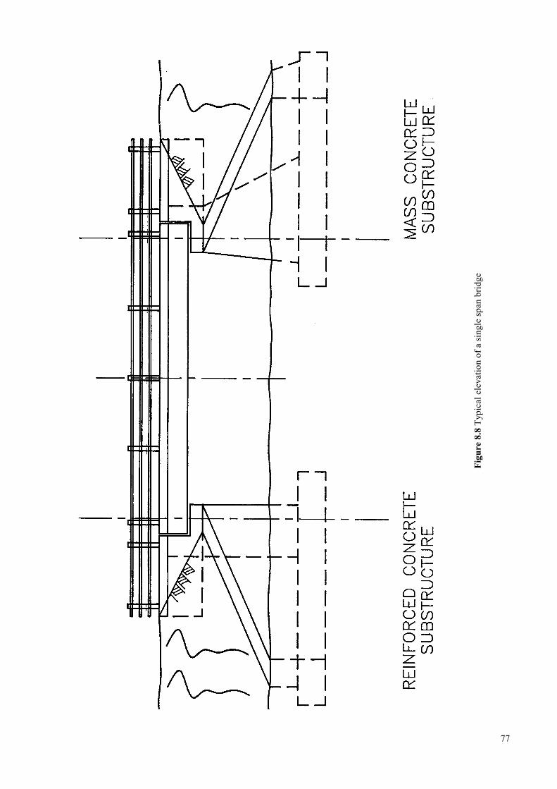
77
Figu
re 8
.8 T
ypic
al e
leva
tion
of a
sing
le sp
an b
ridge
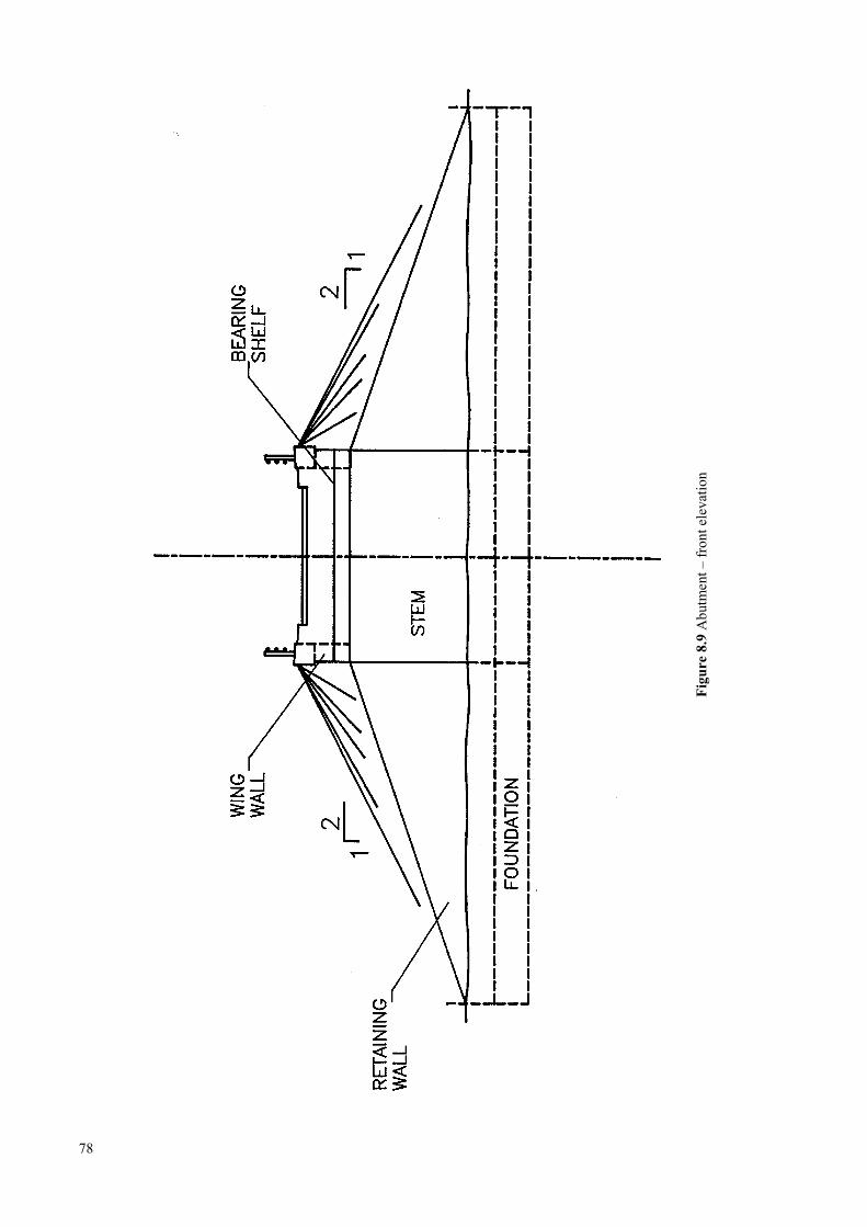
78
Figu
re 8
.9 A
butm
ent –
fron
t ele
vatio
n
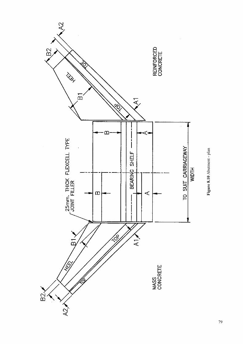
79
Figu
re 8
.10
Abu
tmen
t - p
lan
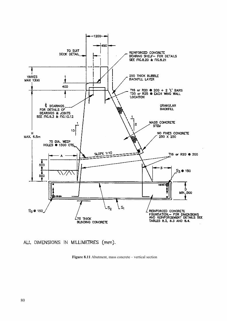
Figure 8.11 Abutment, mass concrete – vertical section
80
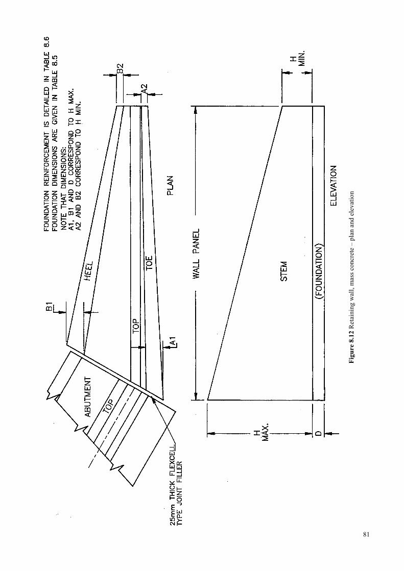
81
Figu
re 8
.12
Ret
aini
ng w
all,
mas
s con
cret
e –
plan
and
ele
vatio
n
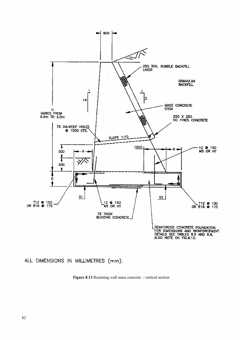
Figure 8.13 Retaining wall mass concrete – vertical section
82
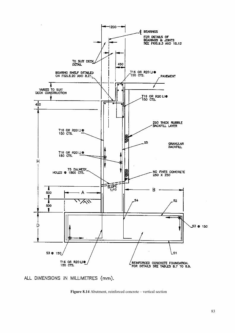
Figure 8.14 Abutment, reinforced concrete – vertical section
83
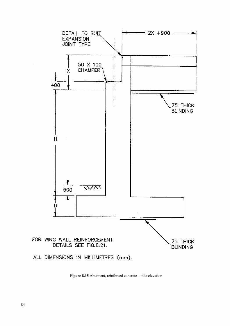
Figure 8.15 Abutment, reinforced concrete – side elevation
84
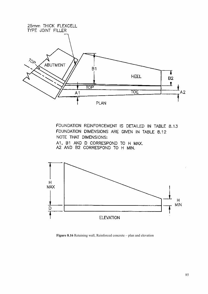
Figure 8.16 Retaining wall, Reinforced concrete – plan and elevation
85
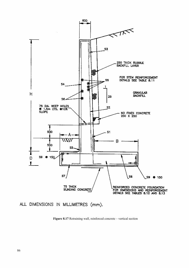
Figure 8.17 Retraining wall, reinforced concrete – vertical section
86
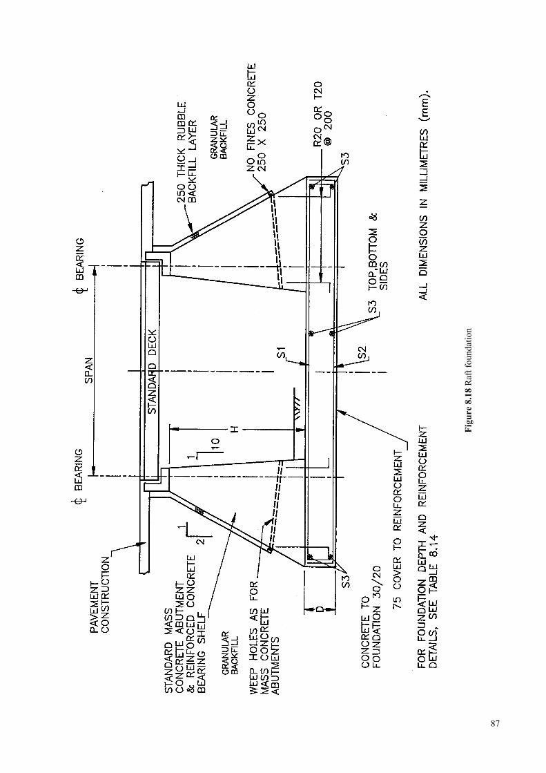
87
Figu
re 8
.18
Raf
t fou
ndat
ion
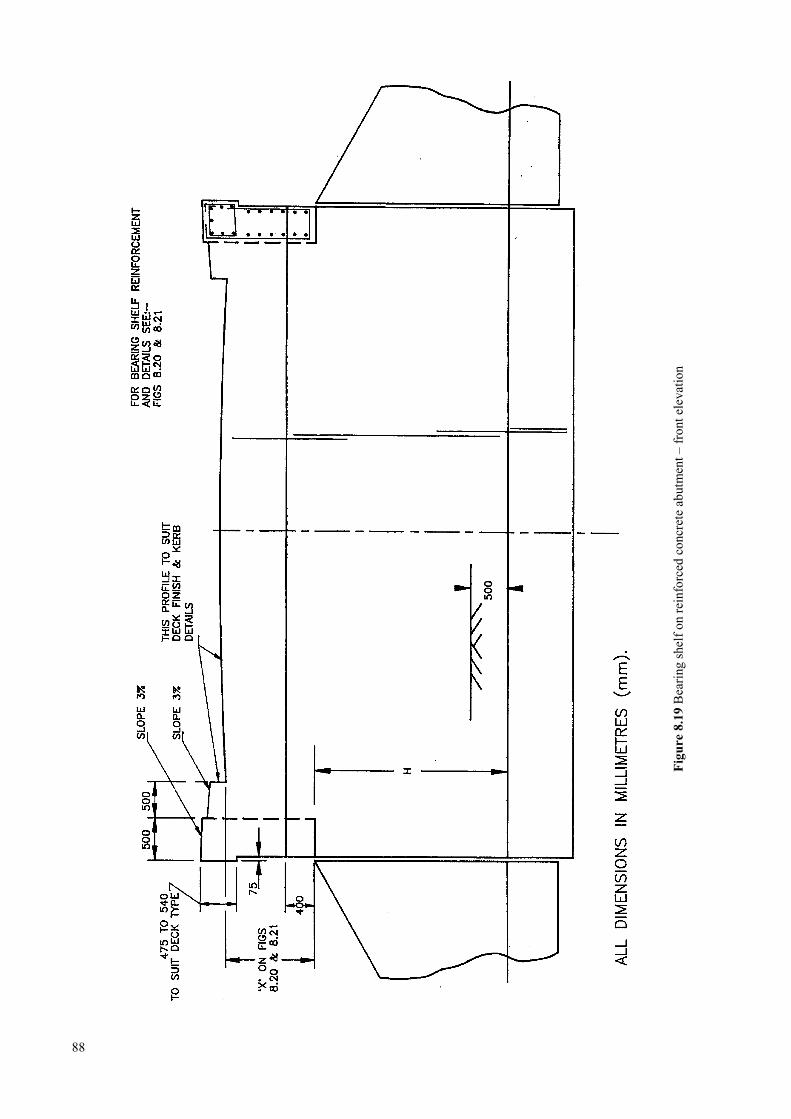
88
Figu
re 8
.19
Bea
ring
shel
f on
rein
forc
ed c
oncr
ete
abut
men
t – fr
ont e
leva
tion
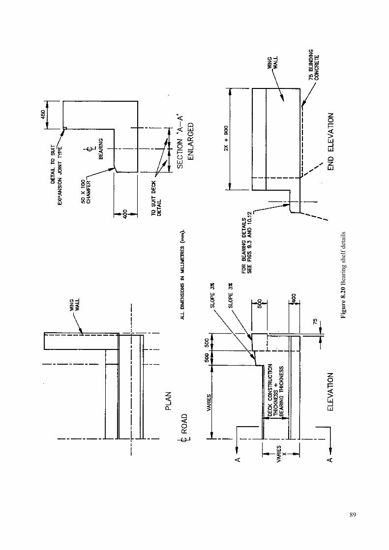
89
Figu
re 8
.20
Bea
ring
shel
f det
ails
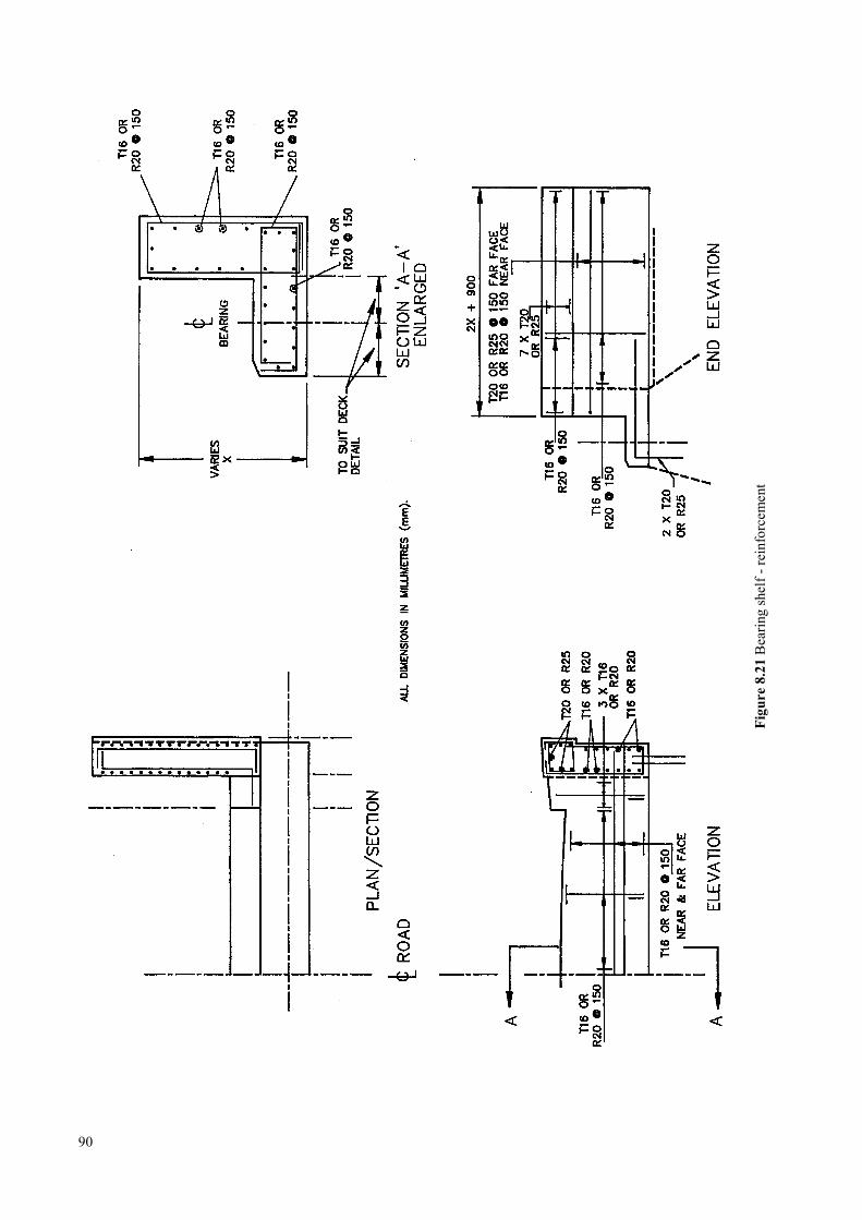
90
Figu
re 8
.21
Bea
ring
shel
f - re
info
rcem
ent
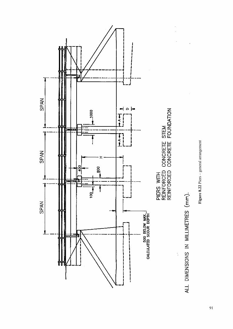
91
Figu
re 8
.22
Pier
s – g
ener
al a
rran
gem
ent
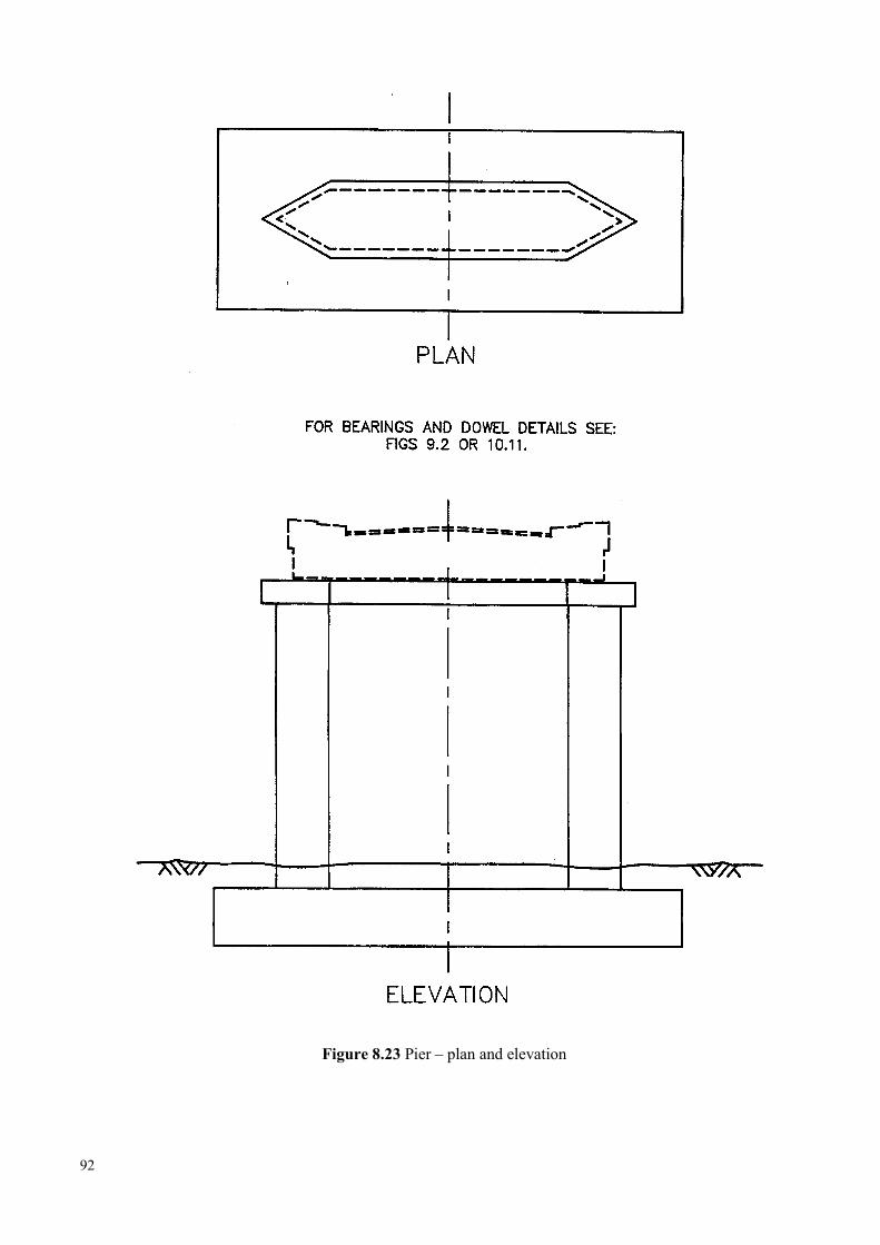
Figure 8.23 Pier – plan and elevation
92
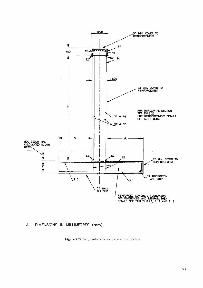
Figure 8.24 Pier, reinforced concrete – vertical section
93
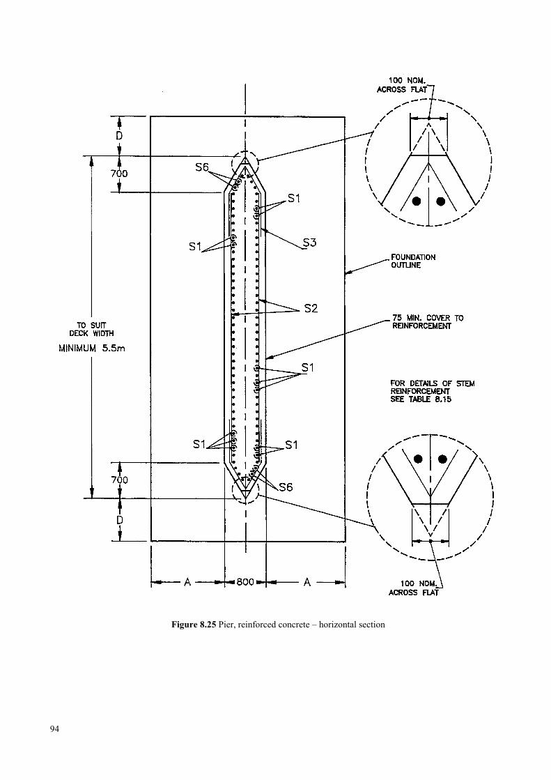
Figure 8.25 Pier, reinforced concrete – horizontal section
94
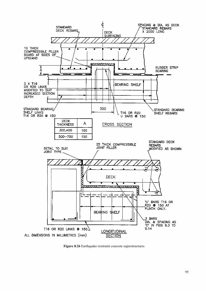
Figure 8.26 Earthquake resitraint concrete superstructures
95
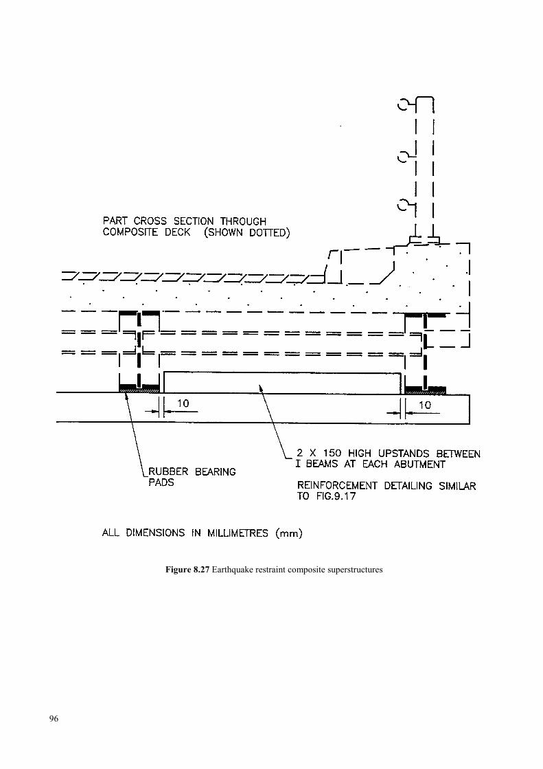
Figure 8.27 Earthquake restraint composite superstructures
96
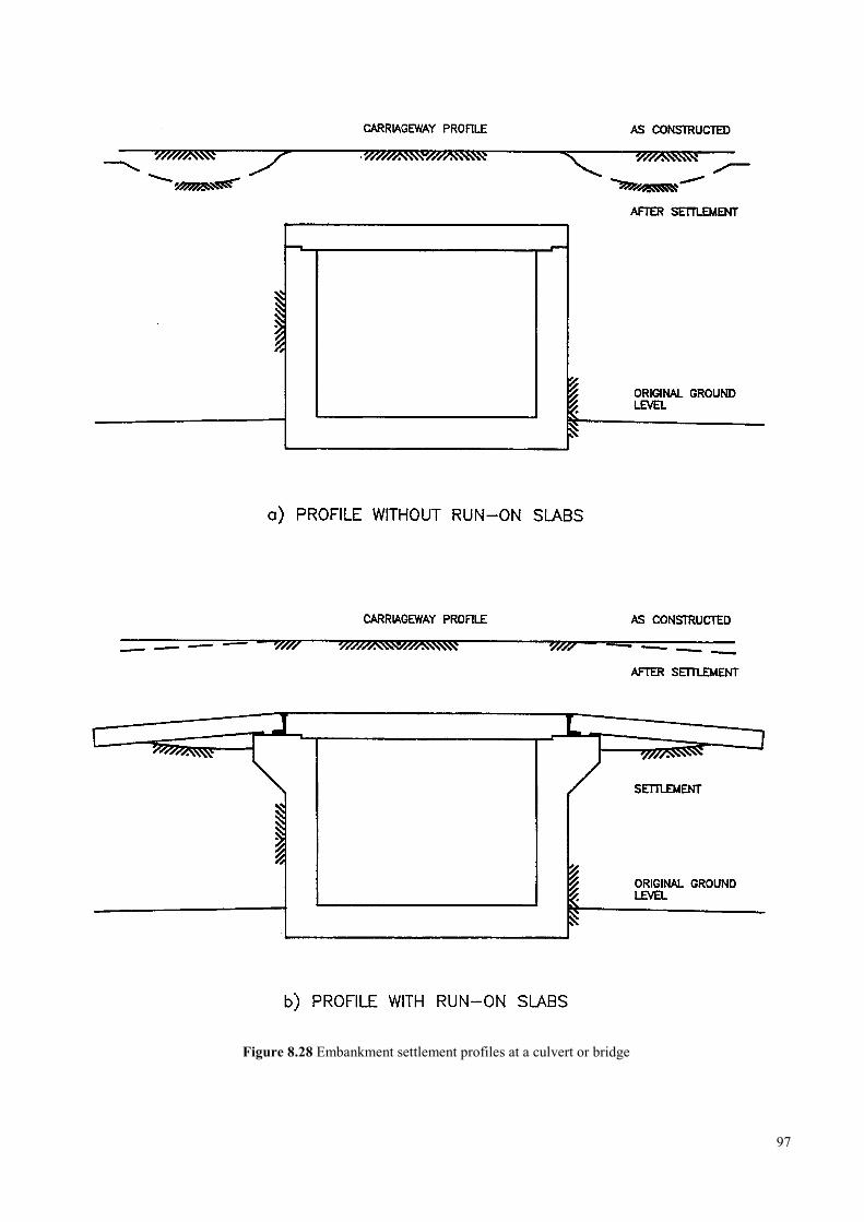
Figure 8.28 Embankment settlement profiles at a culvert or bridge
97
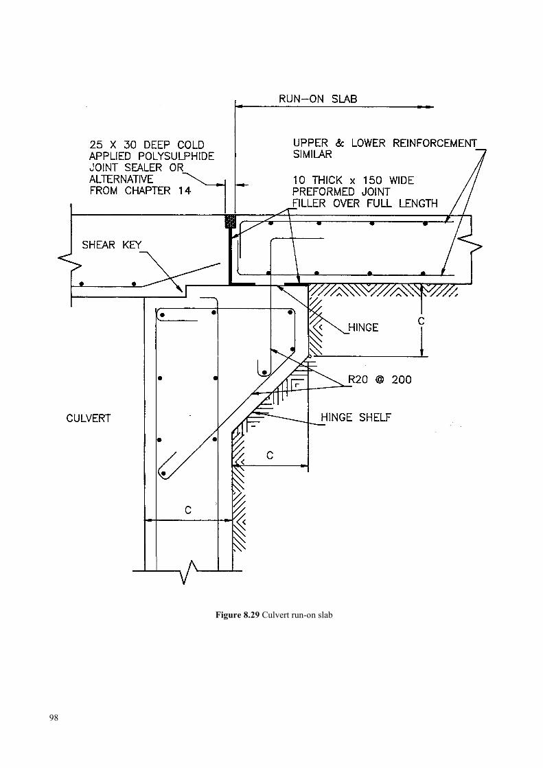
Figure 8.29 Culvert run-on slab
98
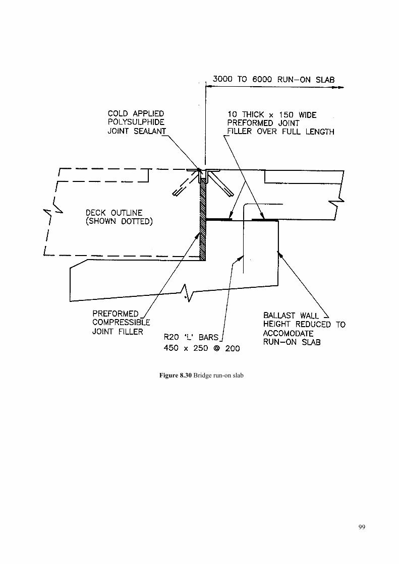
Figure 8.30 Bridge run-on slab
99

8.10.2 Index of tables
Title Table number
Abutment, mass concrete – foundation sixes …………………………………………………………………….…….. 8.2
Abutment mass concrete – high yield steel reinforcement in the foundation …………………………………….……. 8.3
Abutment mass concrete –mild steel reinforcement in the foundation ………………………………………………… 8.4
Retaining wall, mass concrete – foundation sizes ……………………………………………………………………… 8.5
Retaining wall, mass concrete – foundation reinforcement ……………………………………………………………. 8.6
Abutment, reinforced concrete – foundation sizes …………………………………………………………………….. 8.7
Abutment, reinforced concrete – high yield steel reinforcement in the foundation …………………………………… 8.8
Abutment, reinforced concrete – mild steel reinforcement in the foundation …………………………………………. 8.9
Abutment, reinforced concrete – stem reinforcement ………………………………………………………………… 8.10
Retaining wall, reinforced concrete – stem reinforcement …………………………………………………………… 8.11
Retaining wall, reinforced concrete – foundation sizes ………………………………………………………………. 8.12
Retraining wall, reinforced concrete – foundation reinforcement ……………………………………………………. 8.13
Raft foundation – depth and reinforcement ……………………………………………………………………………8.14
Pier stem reinforcement ………………………………………………………………………………………………..8.15
Pier foundation sizes ………………………………………………………………………………………………...... 8.16
Pier foundation – high yield steel reinforcement ………………………………………………………………………8.17
Pier foundation – mild steel reinforcement …………………………………………………………………………… 8.18
Note: The steel reinforcement used in these tables is either:
MS – Plain round mils steel bar, or
HYS – round deformed high tensile steel bar according to the specifications detailed in Section 14.2
100

101
Tabl
e 8.
2 A
butm
ent,
mas
s con
cret
e –
foun
datio
n si
zes (
m)
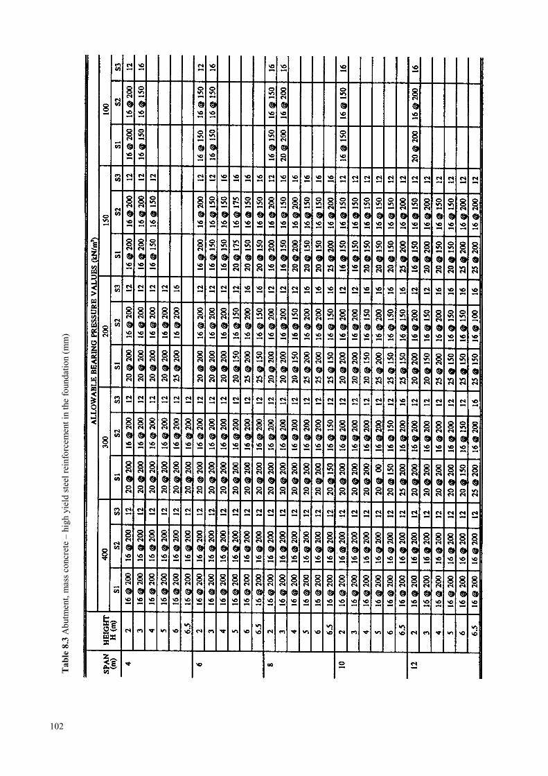
102
Tabl
e 8.
3 A
butm
ent,
mas
s con
cret
e –
high
yie
ld st
eel r
einf
orce
men
t in
the
foun
datio
n (m
m)
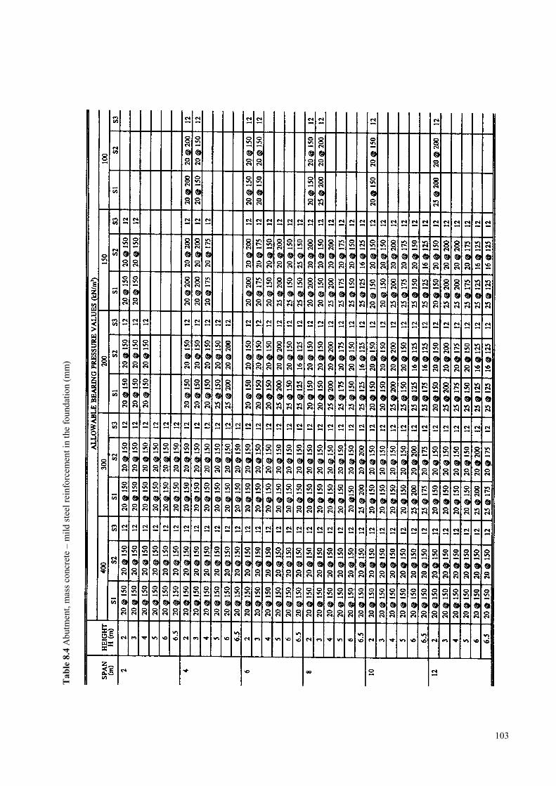
103
Tabl
e 8.
4 A
butm
ent,
mas
s con
cret
e –
mild
stee
l rei
nfor
cem
ent i
n th
e fo
unda
tion
(mm
)
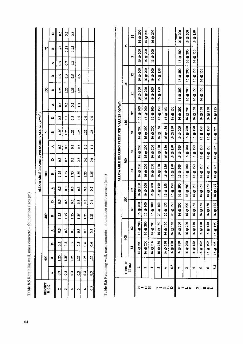
104
Tabl
e 8.
5 R
etai
ning
wal
l, m
ass c
oncr
ete
– fo
unda
tion
size
s (m
)
Tabl
e 8.
6 R
etai
ning
wal
l, m
ass c
oncr
ete
– fo
unda
tion
rein
forc
emen
t (m
m)

105
Tabl
e 8.
7 A
butm
ent,
rein
forc
ed c
oncr
ete
– fo
unda
tion
size
s (m
)
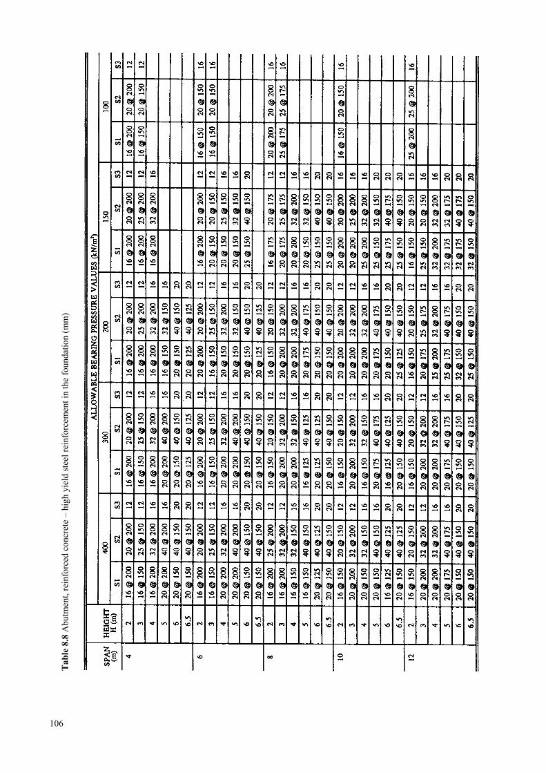
106
Tabl
e 8.
8 A
butm
ent,
rein
forc
ed c
oncr
ete
– hi
gh y
ield
stee
l rei
nfor
cem
ent i
n th
e fo
unda
tion
(mm
)

107
Tabl
e 8.
9 A
butm
ent,
rein
forc
ed c
oncr
ete
– m
ild st
eel r
einf
orce
men
t in
the
foun
datio
n (m
m)
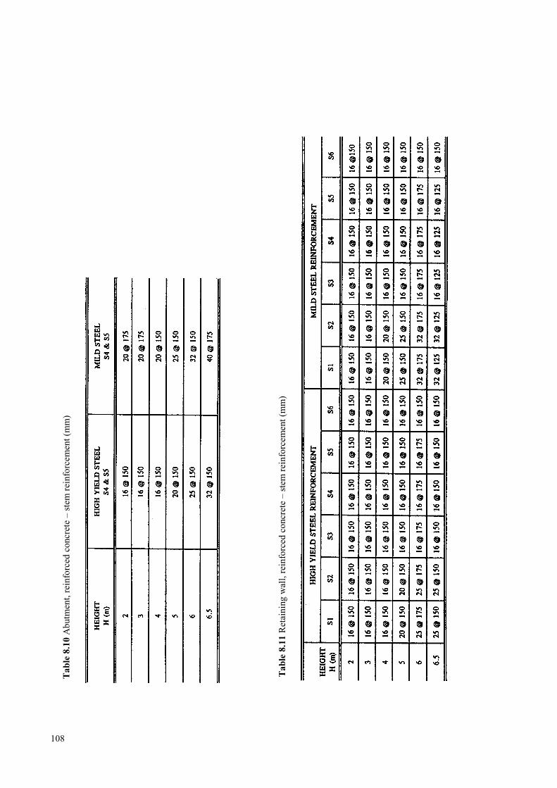
108
Tabl
e 8.
10 A
butm
ent,
rein
forc
ed c
oncr
ete
– st
em re
info
rcem
ent (
mm
)
Tabl
e 8.
11 R
etai
ning
wal
l, re
info
rced
con
cret
e –
stem
rein
forc
emen
t (m
m)
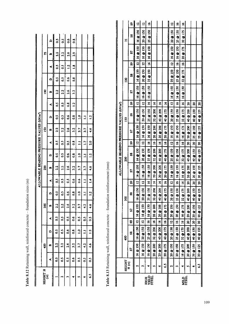
109
Tabl
e 8.
12 R
etai
ning
wal
l, re
info
rced
con
cret
e –
foun
datio
n si
zes (
m)
Tabl
e 8.
13 R
etai
ning
wal
l, re
info
rced
con
cret
e –
foun
datio
n re
info
rcem
ent (
mm
)

110
Tabl
e 8.
14 R
aft f
ound
atio
n –
dept
h an
d re
info
rcem
ent
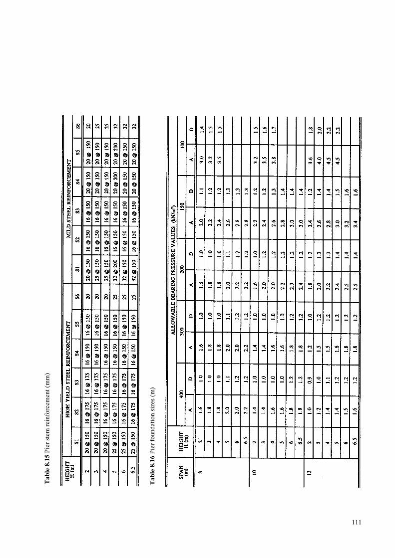
111
Tabl
e 8.
15 P
ier s
tem
rein
forc
emen
t (m
m)
Tabl
e 8.
16 P
ier f
ound
atio
n si
zes (
m)
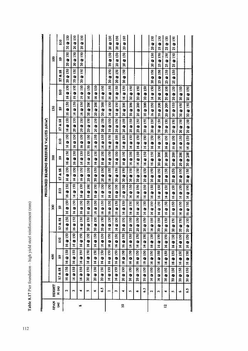
112
Tabl
e 8.
17 P
ier f
ound
atio
n –
high
yie
ld st
eel r
einf
orce
men
t (m
m)
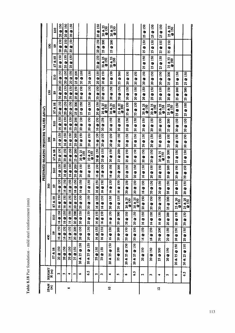
113
Tabl
e 8.
18 P
ier f
ound
atio
n –
mild
stee
l rei
nfor
cem
ent (
mm
)
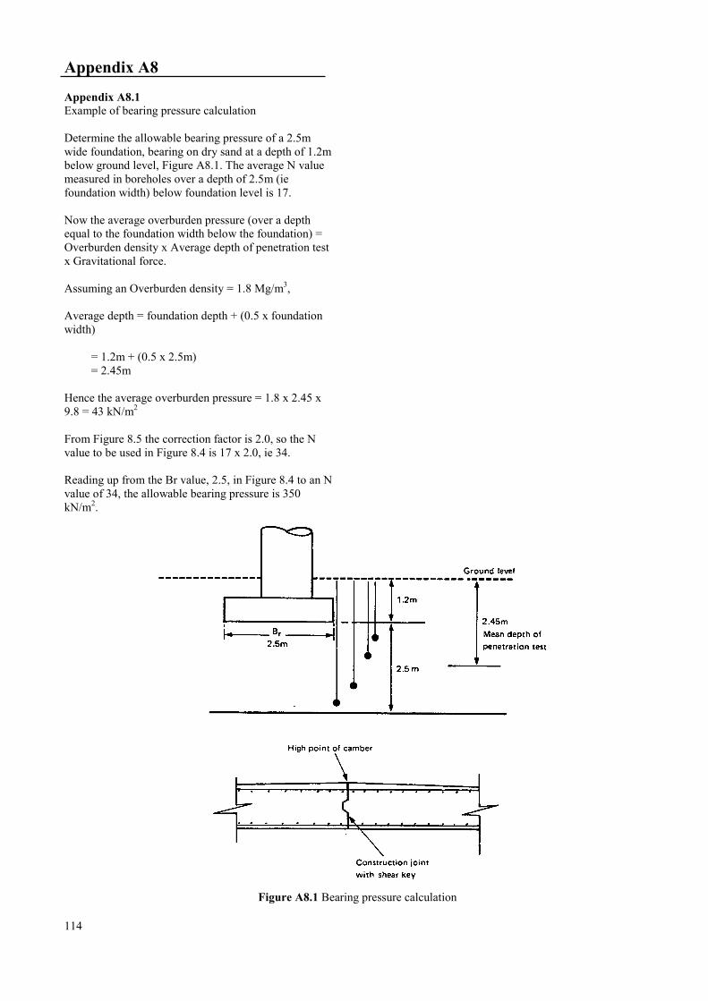
Appendix A8
Appendix A8.1Example of bearing pressure calculation
Determine the allowable bearing pressure of a 2.5mwide foundation, bearing on dry sand at a depth of 1.2mbelow ground level, Figure A8.1. The average N valuemeasured in boreholes over a depth of 2.5m (iefoundation width) below foundation level is 17.
Now the average overburden pressure (over a depthequal to the foundation width below the foundation) =Overburden density x Average depth of penetration testx Gravitational force.
Assuming an Overburden density = 1.8 Mg/m3,
Average depth = foundation depth + (0.5 x foundationwidth)
= 1.2m + (0.5 x 2.5m)= 2.45m
Hence the average overburden pressure = 1.8 x 2.45 x9.8 = 43 kN/m2
From Figure 8.5 the correction factor is 2.0, so the Nvalue to be used in Figure 8.4 is 17 x 2.0, ie 34.
Reading up from the Br value, 2.5, in Figure 8.4 to an Nvalue of 34, the allowable bearing pressure is 350kN/m2.
Figure A8.1 Bearing pressure calculation
114
9 CONCRETE SUPERSTRUCTURES
9.1 Standard designs ………………………………………………………………………………………117
9.2 Design details …………………………………………………………………………………………117
9.2.1 Vertical profile over the bridge ……………………………………………………………117
9.2.2 Bearings …………………………………………………………………………………...117
9.2.3 Expansion joints ………………………………………………………………………….. 117
9.2.4 Construction joints ………………………………………………………………………...118
9.2.5 Slab reinforcement ………………………………………………………………………...118
9.2.6 Drainage …………………………………………………………………………………...118
9.2.7 Parapets ……………………………………………………………………………………118
9.2.8 Surfacing …………………………………………………………………………………..118
9.2.9 Services carried on the bridge ……………………………………………………………..118
9.2.10 Provision for pedestrians and cyclists ……………………………………………………..119
9.3 References …………………………………………………………………………………………….119
9.4 Standard drawings and tables for concrete superstructures …………………………………………..120
115

116
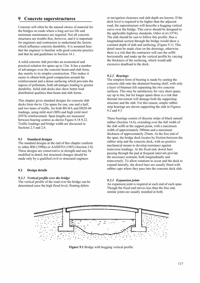
9 Concrete superstructures
Concrete will often be the natural choice of material forthe bridges on roads where a long service life andminimum maintenance are required. Not all concretestructures are trouble-free, however, and it is importantfor engineers and contractors to understand the factorswhich influence concrete durability. It is assumed herethat the engineer is familiar with good concrete practiceand that he and guidelines in Section 14.1.
A solid concrete slab provides an economical andpractical solution for spans up to 12m. It has a numberof advantages over the concrete beam-and-slab form,due mainly to its simpler construction. This makes iteasier to obtain both good compaction around thereinforcement and a dense surfacing which prevents theingress of pollutants, both advantages leading to greaterdurability. Solid slab decks also show better loaddistribution qualities than beam and slab forms.
This chapter gives standard designs for concrete slabdecks form 4m to 12m spans for one, one and a half,and two lanes of traffic, for both BS-HA and HS20-44loadings, using mild steel (MS) and high yield steel(HYS) reinforcement. Span lengths are measuredbetween bearing centres as shown Figure 8.18 8.22.Traffic loadings and bridge width are discussed inSections 2.5 and 2.6.
9.1 Standard designsThe standard designs at the end of this chapter conformto either BSI (1990a) or AASHTO (1983) (Section 2.8).These designs are conservative in strength and may bemodified in detail, but structural changes should bemade only by a qualified civil or structural engineer.
9.2 Design details
9.2.1 Vertical profile over the bridgeThe vertical profile of the road over the bridge can bedetermined once the high flood level, floating debris
or navigation clearance and slab depth are known. If thedeck level is required to be higher than the adjacentroad, the superstructure will describe a hogging verticalcurve over the bridge. This curve should be designed tothe applicable highway standards, Odier et al (1974).The slab should be cast to follow this profile: thus alongitudinal section through the bridge would show aconstant depth of slab and surfacing, (Figure 9.1). Thisdetail must be made clear on the drawings, otherwisethere is a risk that the contractor will cast the soffithorizontally and make up the vertical profile by varyingthe thickness of the surfacing, which would addexcessive deadload to the deck.
9.2.2 BearingsThe simplest form of bearing is made by casting theconcrete slab onto the abutment bearing shelf, with onlya layer of bitumen felt separating the two concretesurfaces. This may be satisfactory for very short spans,say up to 6m, but for longer spans there is a risk thatthermal movement will damage both the supportingstructure and the slab. For this reason, simple rubberstrip bearings are shown supporting the slab in Figures9.2 and 9.3
These bearings consist of discrete strips of black naturalrubber (Section 14.6), extending over the full width ofthe slab soffit at the support point, with a maximumwidth of approximately 300mm and a maximumthickness of approximately 25mm. At the free end ofthe span, the bridge deck locates by friction between therubber strip and the concrete deck, with no positivemechanical means to develop resistance againsttransverse loadings. At the fixed end, dowel barspassing through the pad at frequent intervals providethe necessary restraint, both longitudinally andtransversely. To allow rotations to occur and the deck toexpand laterally, the dowel bars are usually fitted withrubber caps where they pass into the concrete deck slab.
9.2.3 Expansion jointsAn expansion joint is required at each end of each span.Though the fixed end moves less than the free end,similar joints are usually installed at both.
Figure 9.1 Bridge with hogging vertical profile
117
Figure 9.2 shows a suitable joint between adjacent slabsof a multi-span bridge. This same type of joint can beused between the abutments and deck slab (Figure 9.3),one end of the deck being doweled and the other free.Flexible joint seals at the road surface are notrecommended for bridges on gravel roads; Section 14.7describes a more suitable alternative.
9.2.4 Construction jointsConstruction joints often provide paths for the seepageof water, leading to leaching of lime from the concreteand corrosion of the reinforcement. For this reason, it ispreferable for the slab to be cast in one continuouspour. If the engineer knows that this will not bepossible because the batch volume required is too muchfor one day's working, it is better for him to mark onthe drawings a permissible location for constructionjoints. If a joint is unavoidable, it should be parallel tothe centre line and preferably located at the high pointof the transverse camber (Figure 9.16).
9.2.5 Slab reinforcementThe maximum length of reinforcing bar generallyavailable is 12m. When a longer bar is needed, eg for a12m span, two bars must be lapped. As a general rulethe lap length should be at least 40 times the diameterof the bar. The main bars should not be lapped near thecentre of the span, and laps should be staggered so thatthey do not cause a line of weakness across the slab.The lapping of bars should be avoided wheneverpossible so as to ensure good continuity, minimisecongestion of reinforcement and so produce bettercompaction of concrete around the steel.
The anchorage and positioning and reinforcement areparticularly important where the slab sits on itsbearings. For the standard designs all bars have beencontinued to the supports. Main bars are L-bars, markedC in Figures 9.4 to 9.15, and are positioned with thehooks at alternate ends. It is important to position the90 degree hook so that the bend begins behind thebearing, as shown on the drawings.
Accurate positioning of the reinforcement is essential inorder to maintain the minimum cover of 50mm of wellcompacted concrete, and so avoid moisture andpollutants penetrating the slab and corroding the steelreinforcement.
9.2.6 DrainageIf the bridge is single span with a hogging verticalcurve and the joints between deck and abutments aresealed, surface water can be allowed to run off thebridge into the road drainage channels and no drains arerequired on the bridge superstructure.
If the bridge is multi-span, or has a flat or sagging
118
profile with a low point on the bridge, drains must beinstalled on the deck. The simplest way is to provide a100mm diameter PVC pipe at the kerb line, dishing theconcrete around it, and setting a metal gully grating inthe surfacing (Figure 9.16). The engineer must take careto see that the discharge does not cause damage toservices or sub-structures, and ensure that closeattention is given to the compaction of the deckconcrete around the pipe.
9.2.7 ParapetsFigure 9.17 shows details of a suitable steel parapetsystem. These follow the general principles of theHighways Agency (1993) but circular sections havebeen selected for the rails since they are more readilyavailable in most countries. Badly damaged posts orrails can be unbolted and replaced. If proprietary squaresection beams are available, they should be usedbecause they cause less damage to vehicles on impact.'W section' guardrails may also be used to good effect.
Provision should be made for differential expansionand contraction between steel and concrete elements,particularly at the superstructure expansion joints.
To reduce the danger of a rail penetrating a vehicle onimpact, parapet rails should present a continuous face totraffic, even at expansion joints.
Care should be taken with details of the holding-downfixing into the concrete plinth. As well as installing themetre-long bars through the U-bars, two extra links(reinforcement bar marked D in Figures 9.3 to 9.14)should be used at each post position, one each sideclose to the U-bars. Bridge parapets usually extendseveral metres beyond the superstructure at each end,and may be supported by the wing walls, in order toprovide a barrier at the approaches.
9.2.8 SurfacingThe standard slabs are designed to be used with 75mmof asphalt surfacing. This provides some degree ofwaterproofing and protection of the surface of thestructural slab. In some countries it is common practiceto use the upper surface of the slab as a running surface.This is not recommended, but should the engineer wishto avoid using asphalt, the minimum cover toreinforcement in the top of the slab should be increasedto 75mm and kerb joint and drainage details have to bemodified accordingly. Bridges serving gravel roadsmay need more than 75mm cover to counteract theabrasive action of stones embedded in vehicle tyres.
9.2.9 Services carried on the bridgeIt will sometimes be necessary to make provision forservices and utilities such as electricity or telephone
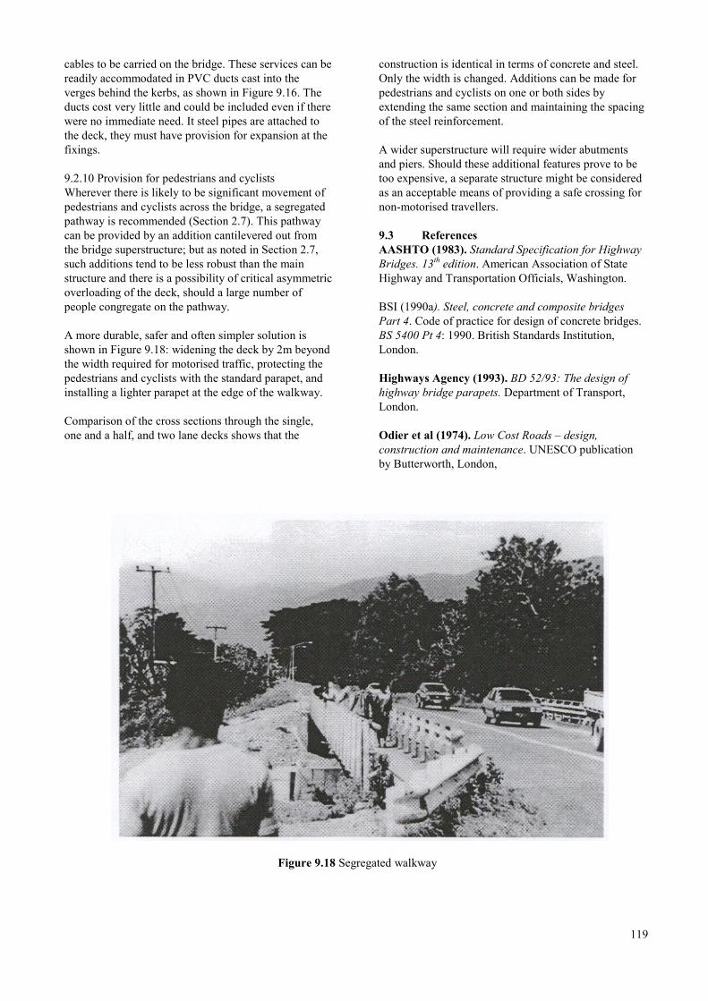
cables to be carried on the bridge. These services can bereadily accommodated in PVC ducts cast into theverges behind the kerbs, as shown in Figure 9.16. Theducts cost very little and could be included even if therewere no immediate need. It steel pipes are attached tothe deck, they must have provision for expansion at thefixings.
9.2.10 Provision for pedestrians and cyclistsWherever there is likely to be significant movement ofpedestrians and cyclists across the bridge, a segregatedpathway is recommended (Section 2.7). This pathwaycan be provided by an addition cantilevered out fromthe bridge superstructure; but as noted in Section 2.7,such additions tend to be less robust than the mainstructure and there is a possibility of critical asymmetricoverloading of the deck, should a large number ofpeople congregate on the pathway.
A more durable, safer and often simpler solution isshown in Figure 9.18: widening the deck by 2m beyondthe width required for motorised traffic, protecting thepedestrians and cyclists with the standard parapet, andinstalling a lighter parapet at the edge of the walkway.
Comparison of the cross sections through the single,one and a half, and two lane decks shows that the
construction is identical in terms of concrete and steel.Only the width is changed. Additions can be made forpedestrians and cyclists on one or both sides byextending the same section and maintaining the spacingof the steel reinforcement.
A wider superstructure will require wider abutmentsand piers. Should these additional features prove to betoo expensive, a separate structure might be consideredas an acceptable means of providing a safe crossing fornon-motorised travellers.
9.3 ReferencesAASHTO (1983). Standard Specification for HighwayBridges. 13th edition. American Association of StateHighway and Transportation Officials, Washington.
BSI (1990a). Steel, concrete and composite bridgesPart 4. Code of practice for design of concrete bridges.BS 5400 Pt 4: 1990. British Standards Institution,London.
Highways Agency (1993). BD 52/93: The design ofhighway bridge parapets. Department of Transport,London.
Odier et al (1974). Low Cost Roads – design,construction and maintenance. UNESCO publicationby Butterworth, London,
Figure 9.18 Segregated walkway
119
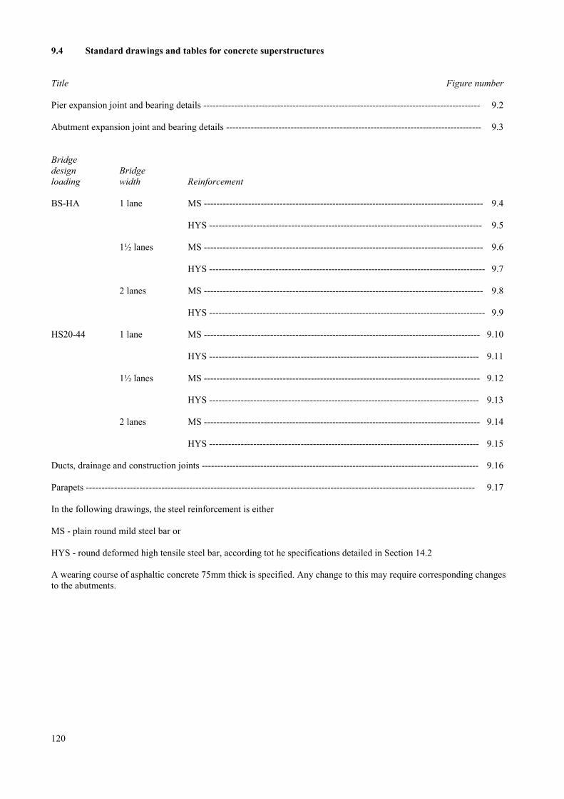
9.4 Standard drawings and tables for concrete superstructures
Title Figure number
Pier expansion joint and bearing details ------------------------------------------------------------------------------------------ 9.2
Abutment expansion joint and bearing details ----------------------------------------------------------------------------------- 9.3
Bridgedesign Bridgeloading width Reinforcement
BS-HA 1 lane MS ------------------------------------------------------------------------------------------ 9.4
HYS ---------------------------------------------------------------------------------------- 9.5
1½ lanes MS ------------------------------------------------------------------------------------------ 9.6
HYS ----------------------------------------------------------------------------------------- 9.7
2 lanes MS ------------------------------------------------------------------------------------------ 9.8
HYS ----------------------------------------------------------------------------------------- 9.9
HS20-44 1 lane MS ----------------------------------------------------------------------------------------- 9.10
HYS --------------------------------------------------------------------------------------- 9.11
1½ lanes MS ----------------------------------------------------------------------------------------- 9.12
HYS --------------------------------------------------------------------------------------- 9.13
2 lanes MS ----------------------------------------------------------------------------------------- 9.14
HYS --------------------------------------------------------------------------------------- 9.15
Ducts, drainage and construction joints ------------------------------------------------------------------------------------------ 9.16
Parapets ------------------------------------------------------------------------------------------------------------------------------ 9.17
In the following drawings, the steel reinforcement is either
MS - plain round mild steel bar or
HYS - round deformed high tensile steel bar, according tot he specifications detailed in Section 14.2
A wearing course of asphaltic concrete 75mm thick is specified. Any change to this may require corresponding changesto the abutments.
120

Figure 9.2 Concrete superstructure, pier expansion joint and bearing details
121
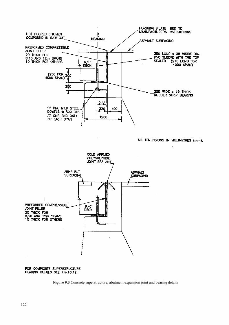
Figure 9.3 Concrete superstructure, abutment expansion joint and bearing details
122
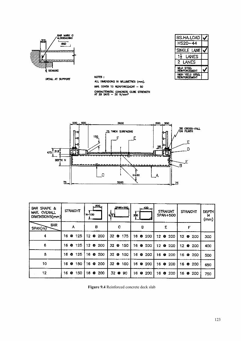
Figure 9.4 Reinforced concrete deck slab
123
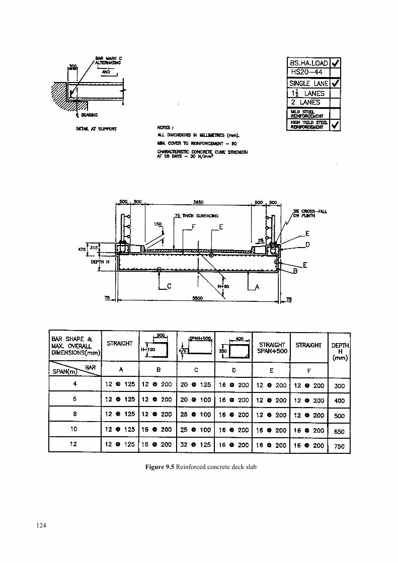
Figure 9.5 Reinforced concrete deck slab
124
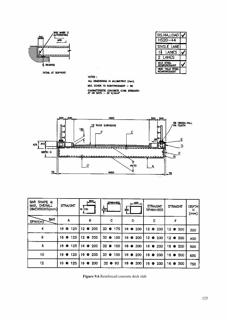
Figure 9.6 Reinforced concrete deck slab
125
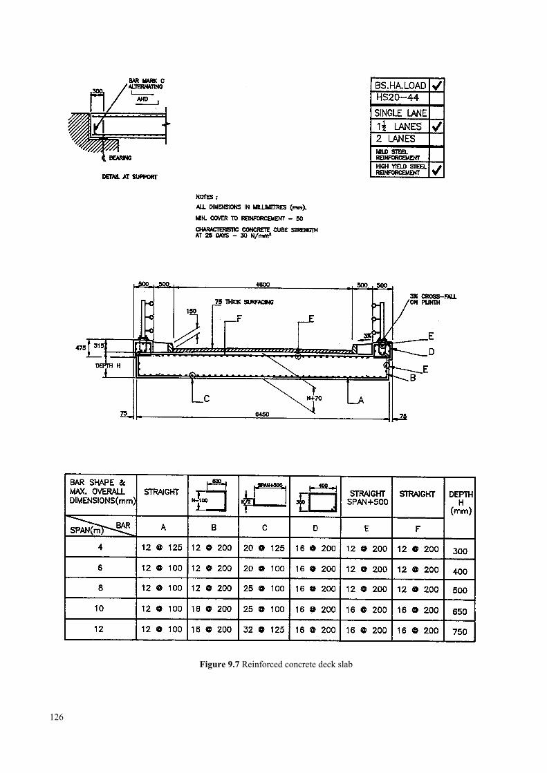
Figure 9.7 Reinforced concrete deck slab
126
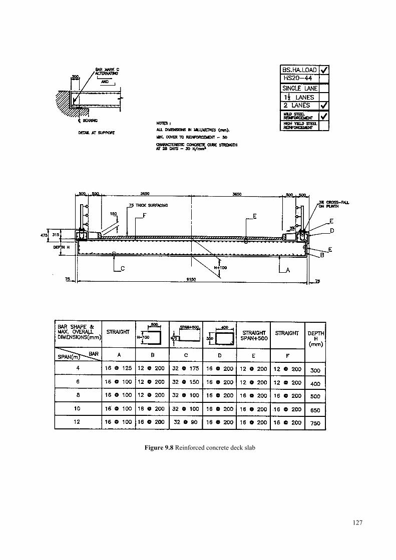
Figure 9.8 Reinforced concrete deck slab
127
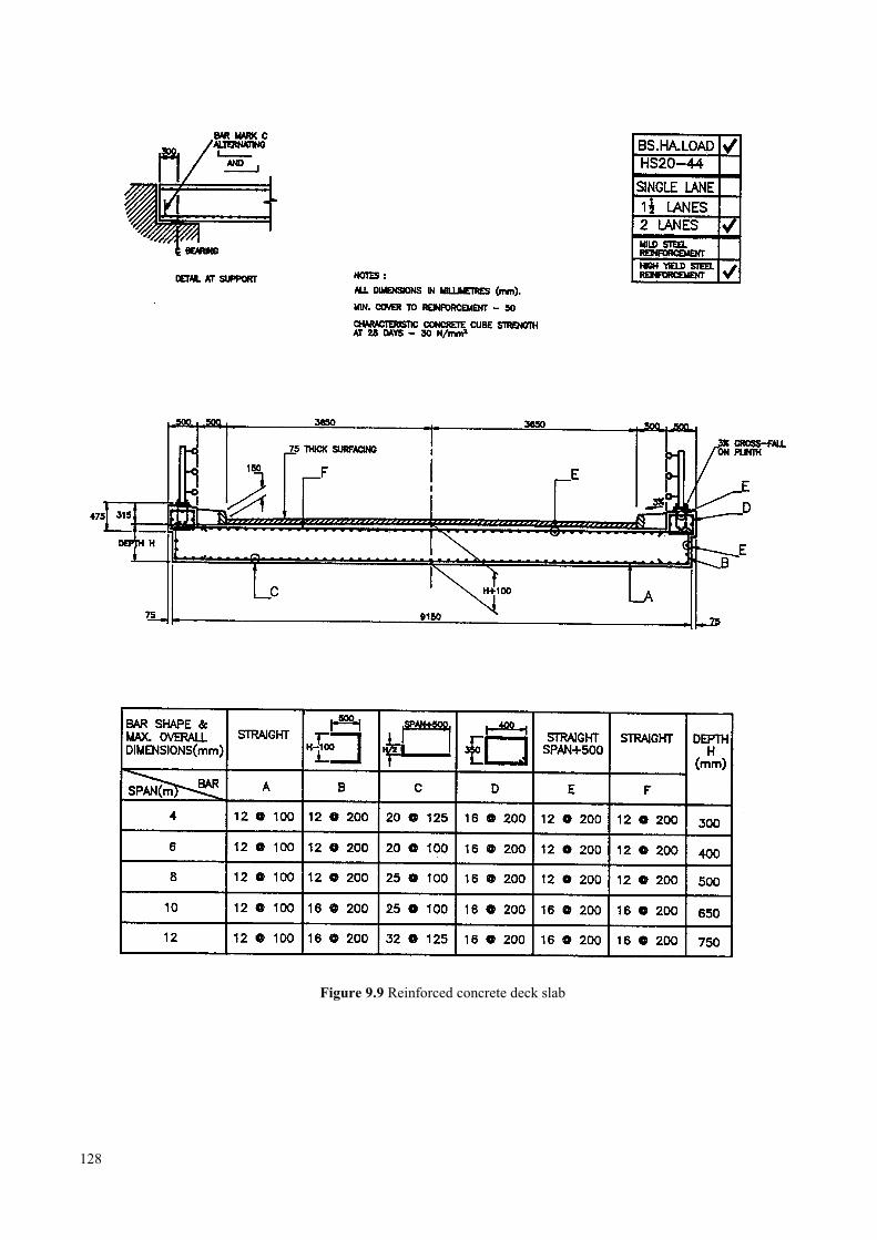
Figure 9.9 Reinforced concrete deck slab
128
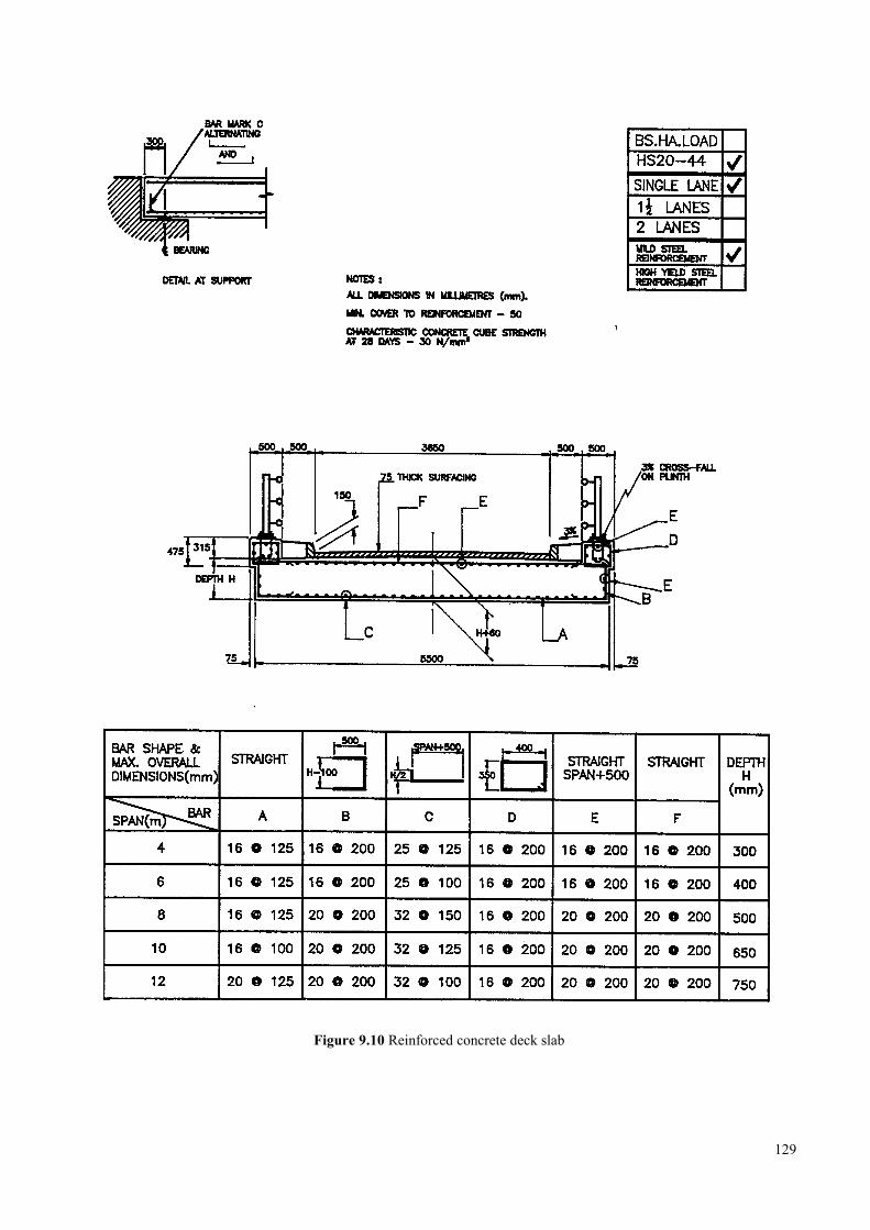
Figure 9.10 Reinforced concrete deck slab
129
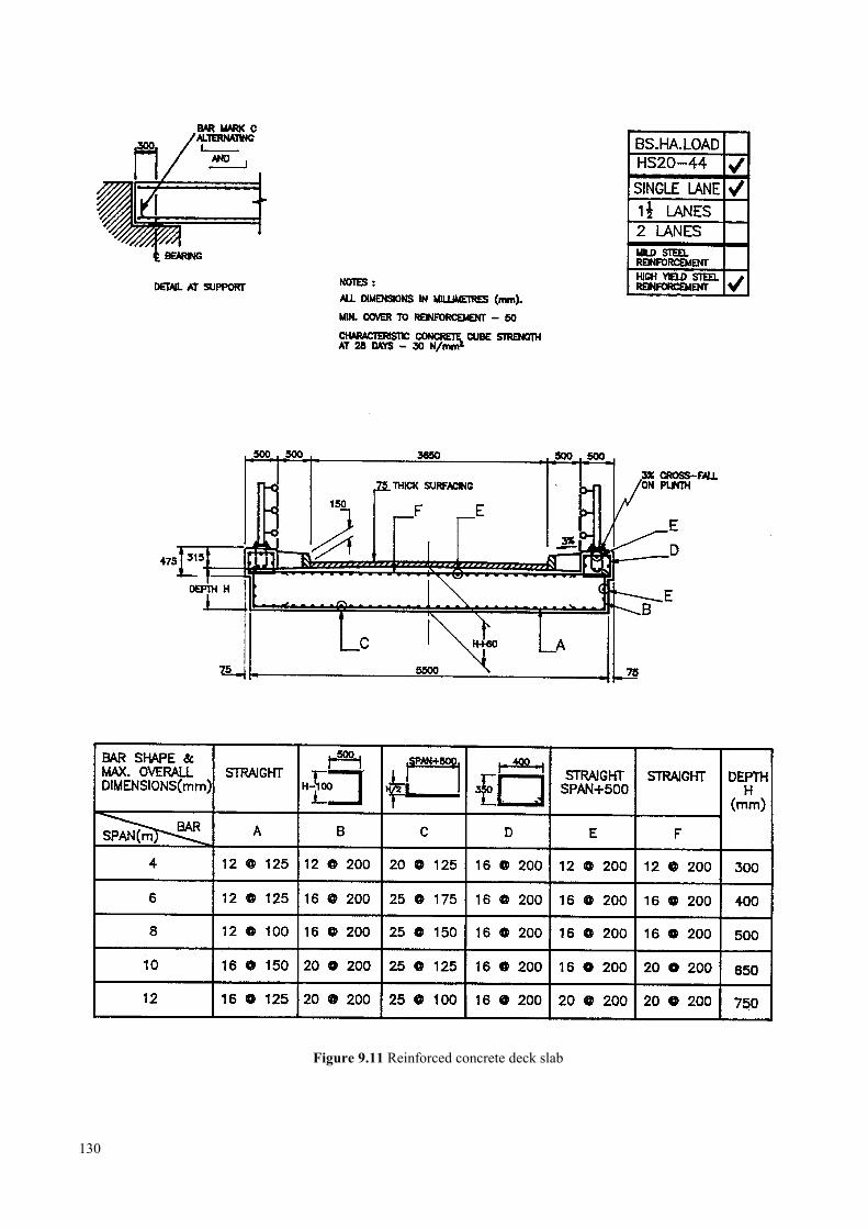
Figure 9.11 Reinforced concrete deck slab
130
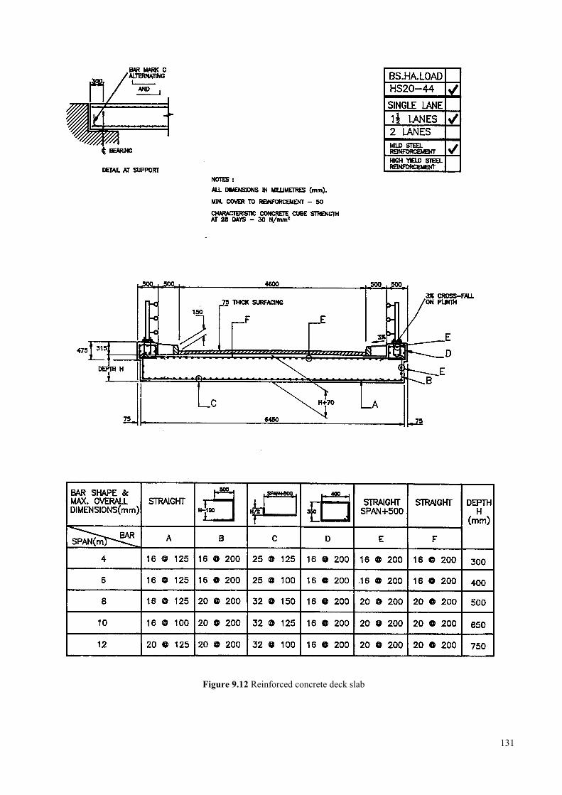
Figure 9.12 Reinforced concrete deck slab
131
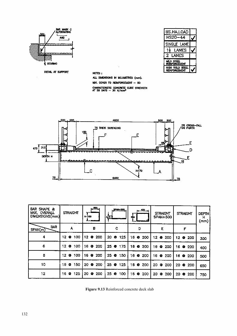
Figure 9.13 Reinforced concrete deck slab
132
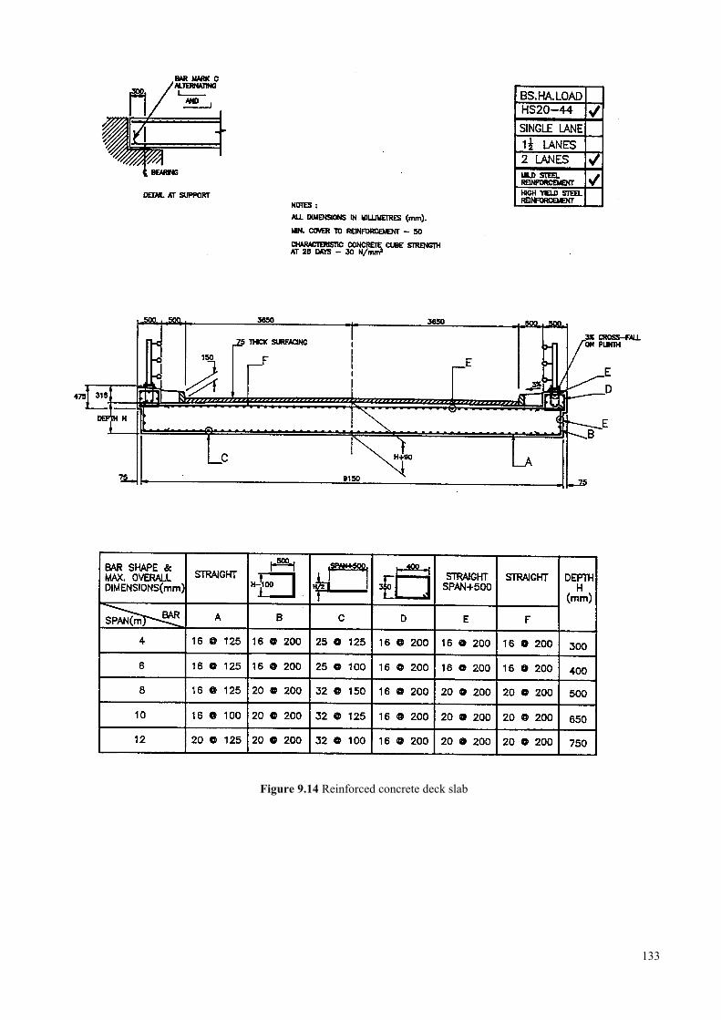
Figure 9.14 Reinforced concrete deck slab
133
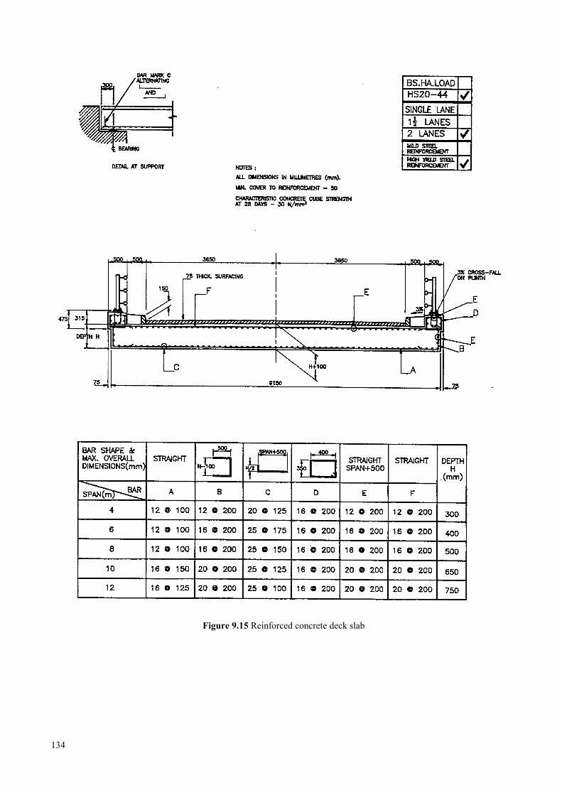
Figure 9.15 Reinforced concrete deck slab
134
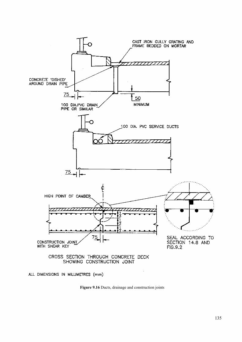
Figure 9.16 Ducts, drainage and construction joints
135
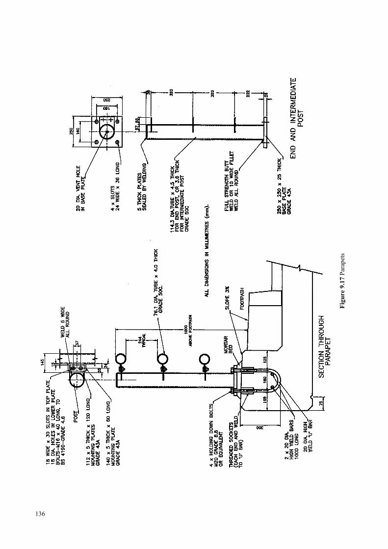
136
Figu
re 9
.17
Para
pets
10 STEEL/CONCRETE COMPOSITE SUPERSTRUCTURES
10.1 Design standards …………………………………………………………………………………. 139
10.2 Design details …………………………………………………………………………………….. 139
10.2.1 Vertical profile over the bridge ………………………………………………………. 139
10.2.2 Construction ………………………………………………………………………….. 139
10.2.3 Shear connectors …………………………………………………………………….. 139
10.2.4 Protective treatment to steelwork …………………………………………………….. 140
10.2.5 Bolts and nuts ………………………………………………………………………… 140
10.2.6 Bearings ………………………………………………………………………………. 140
10.2.7 Expansion joints ……………………………………………………………………… 140
10.2.8 Construction joints …………………………………………………………………… 140
10.2.9 Slab reinforcement …………………………………………………………………… 140
10.2.10 Drainage ……………………………………………………………………………… 140
10.2.11 Parapets, surfacing and services ……………………………………………………… 140
10.2.12 Provision for pedestrians and cyclists ………………………………………………… 140
10.3 References ………………………………………………………………………………………… 140
10.4 Standards drawings and tables for composite superstructures …………………………………… 141
137

138
10 Steel/concrete compositesuperstructures
In countries without an indigenous steel industry, theneed to use foreign exchange for structural steelworkoften inhibits designers from considering steel bridges.However, there are situations in which the use ofsteelwork will be both technically appropriate and cost-effective.
Because they are easy both to erect and remove, andcan be used again elsewhere, steel beams with a timberdecking are often a good solution for structuresintended to have a short service life (ie no more than 10years). Their durability, however, is limited by theinability of the decking to prevent surface water anddirt from penetrating through to the steel main beams.Though regular maintenance painting can preventdeterioration of the beam webs and bottom flanges,serious corrosion can occur at the inaccessible beam topflanges, where the timber and steel meet.
Where structures are intended to be permanent, thedurability of the steel over a service life of 50 years ormore can be achieved more readily by the use of a castin situ concrete deck slab. Composite action of the slaband beams is secured by the use of shear connectorswelded to the top flanges of the beams and cast into theconcrete.
As an alternative to the solid concrete slab decksdescribed in Chapter 9, this chapter details a series ofstandard bridge decks constructed from steel universalbeams (UB) with a composite concrete deck slab. Themain beams and cross members are of standard rolledcarbon steel sections (yield stress 274N/mm2, with deckslab reinforcement in either mild steel (MS) or highyield steel (HYS). The steel and concrete specificationsare given in Chapter 14.
Steel/concrete composite deck structures have thefollowing advantages:
• The deck self weight can be less than that of anequivalent all-concrete structure.
• The off-site prefabrication of the main load-carrying elements of the bridge substantiallyreduces the work necessary on site, resulting inmore rapid construction.
• No temporary supports are required during of thedeck slab, since the soffit shutters can be supporteddirectly from the steel beams. This can be aparticular advantage at locations with poor groundconditions, steeply sloping terrain, or with a faststream.
• Steel is a reliable material which is supplied withguaranteed strength properties, enabling structuresof high and consistent reliability to be produced.
10.1 Design standardsThe bridge decks detailed in this chapter range from 6mto 12m in length with roadway widths of one, one and ahalf, and two lanes. Span lengths are measured betweenbearing centres as shown in Figures 8.18 and 8.22: thedesigns are in accordance with BSI (1979) for HAloading and AASHTO (1985) for HS20-44 loading.
10.2 Design details
10.2.1 Vertical profile over the bridgeThe bridge should preferably be constructed either to alevel profile or to a constant longitudinal grade, if thisis required by the road alignment. The steel beams canbe cambered to give some degree of hogging verticalcurvature should the equipment be available, but thecost is unlikely to be justifiable.
10.2.2 ConstructionThe heaviest beams required for the standard bridgesdetailed in Figures 10.1 to 10.11, ie those for a 12mspan length, weigh less than two tonnes. They maytherefore be erected using a small mobile crane orimprovised lifting equipment. Alternatively, the beamsmay be pushed or pulled out over the gap being bridgedusing some form of intermediate temporary supportand/or a light launching nose attached to the beams.
Propping of the steel beams during deck concreting isunnecessary, since the steel section has been designedto be adequate to support the wet concrete, soffitshutters and construction loading.
The engineer must appreciate that the wet concreteloading constitutes a critical design case for the steelbeams. Wind loading at this stage adds significantly tothe stresses in the beams. For this reason, it is necessaryto ensure that the concrete slab is not poured if windspeeds of 1 8mlsec (40mph) or more are occurring orare expected within the following 48 hours.
10.2.3 Shear connectorsThese connectors are the only links between theconcrete slab, acting in compression and bending whenunder load, and the steel beams, acting in tension andbending. The largest shear forces act at each end of thedeck, where the shear connectors are spaced closertogether. Figure 10.7 gives the dimensions and spacingfor each span and load rating.
Welded channel shear connectors are specified, sincethey can be produced from readily available materialand fixed locally. The joints, however, should be ofgood quality welding and be protected from corrosionin storage.
139

10.2.4 Protective treatment to steelworkThe degree of protection which the steelwork willrequire depends on the local environment. Particularcare will be needed for structures in coastal locations orwhere there is significant atmospheric pollution.
Types of paint used and surface preparation methodswill depend on the local availability of materials andequipment. The engineer should try to achieve thefollowing standard in order to ensure a reasonable lifeto first maintenance:
l) grit blasting to remove millscale, loose rust,welding scale etc., and produce a clean surface forpainting;
2) application of a multi-coat paint system to a totaldry film thickness of 0.25mm.
At least one paint coat should be applied at site aftercompletion of construction, so that damage topaintwork incurred during transport, steel erection andconcreting can be repaired.
10.2.5 Bolts and nutsOrdinary bolts, grade 8.8 to ISO (1982) together withgrade 8 nuts, are specified for fixing cross members.Alternatives should match the tensile strength of 80kgflmm2 with a minimum elongation at fracture of 12%.
10.2.6 BearingsElastomeric bearings, as detailed in Sections 9.2.2 and14.6, are specified because they are durable,inexpensive and simple to install.
10.2.7 Expansion jointsAt these relatively short deck lengths, joint movementsdue to temperature and live loading are small and arereadily accommodated by a simple gap joint, asindicated in Figures 10.11 and 10.12. The joint is sealedby a polysulphide sealant to prevent water penetration.An alternative unsealed joint, more suitable for bridgeson gravel roads, is described in Section 14.7.
10.2.8 Construction jointsAs discussed in Section 9.2.4, it is best if the slab canbe cast in one continuous pour. If this will not bepracticable, permissible locations for construction jointsshould be marked on the drawings. If a joint isunavoidable, it should be perpendicular to the centreline at a location least likely to promote corrosion inunderlying steelwork.
140
10.2.9 Slab reinforcementAs noted in Section 9.2.5, the maximum length ofreinforcing bar generally available is 12m. Where alonger bar is required, eg for a 12m span bridge, twobars must be lapped. The lap length should be at least40 times the diameter of the lapped bars and laps shouldbe staggered both to avoid a line of weakness and tominimise congestion of reinforcement. Main bars are L-bars, marked C in Figures 10.4 to 10.6, and arepositioned with the hooks at alternate ends.
Accurate positioning of the reinforcement is essential inorder to maintain the minimum cover of 50mm of wellcompacted concrete, so that moisture and pollutantscannot penetrate the slab as far as the reinforcing barand corrode it.
10.2.10 DrainageDrainage should be provided if required, generally asdetailed for concrete slab bridges (Section 9.2.6. andFigure 9.16). Down pipes must be of sufficient lengthto ensure that run-off water is discharged at least150mm clear below the beam lower flanges.
10.2.11 Parapets, surfacing and servicesParapet and surfacing details are the same as forconcrete slab bridges (Sections 9.2.7 and 9.2.8). If ductsfor services are required, they can be provided as setout in Section 9.2.9.
10.2.12 Provision for pedestrians and cyclistsThe recommendations set out in Section 9.2.10 onpathways for pedestrians and cyclists on concrete decksapply equally to composite decks. The addition of a 2mwide walkway to a composite deck of the type detailedhere would also require one more I beam to match thosefor the road bridge.
10.3 ReferencesAASHTO (1985). Standard specifications for highwaybridges, 13th edition. American Association of StateHighway and Transportation Officials, Washington.
BSI (1979). Steel, concrete and composite bridgesPart 5. Code of practice for the design of compositebridges. BS 5400 Pt 5: 1979. British StandardsInstitution, London.
ISO (1982). Fasteners - hexagon products-widthsacross flats. ISO 272:1982
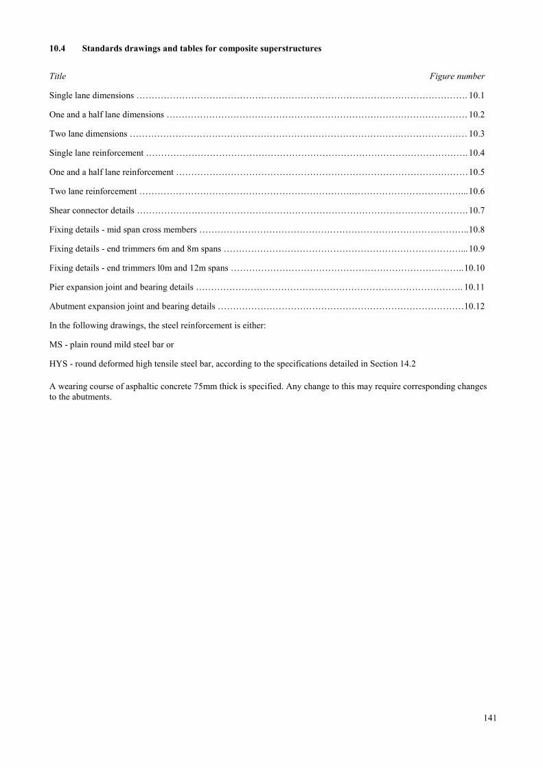
10.4 Standards drawings and tables for composite superstructures
Title Figure number
Single lane dimensions ………………………………………………………………………………………………. 10.1
One and a half lane dimensions ………………………………………………………………………………………10.2
Two lane dimensions ………………………………………………………………………………………………… 10.3
Single lane reinforcement …………………………………………………………………………………………….10.4
One and a half lane reinforcement ……………………………………………………………………………………10.5
Two lane reinforcement …………………………………………………………….………………………………...10.6
Shear connector details ……………………………………………………………………………………………….10.7
Fixing details - mid span cross members ……………………………………………………………………………..10.8
Fixing details - end trimmers 6m and 8m spans ……………………………………………………………………...10.9
Fixing details - end trimmers l0m and 12m spans …………………………………………………………………..10.10
Pier expansion joint and bearing details ……………………………………………………………………………. 10.11
Abutment expansion joint and bearing details ………………………………………………………………………10.12
In the following drawings, the steel reinforcement is either:
MS - plain round mild steel bar or
HYS - round deformed high tensile steel bar, according to the specifications detailed in Section 14.2
A wearing course of asphaltic concrete 75mm thick is specified. Any change to this may require corresponding changesto the abutments.
141
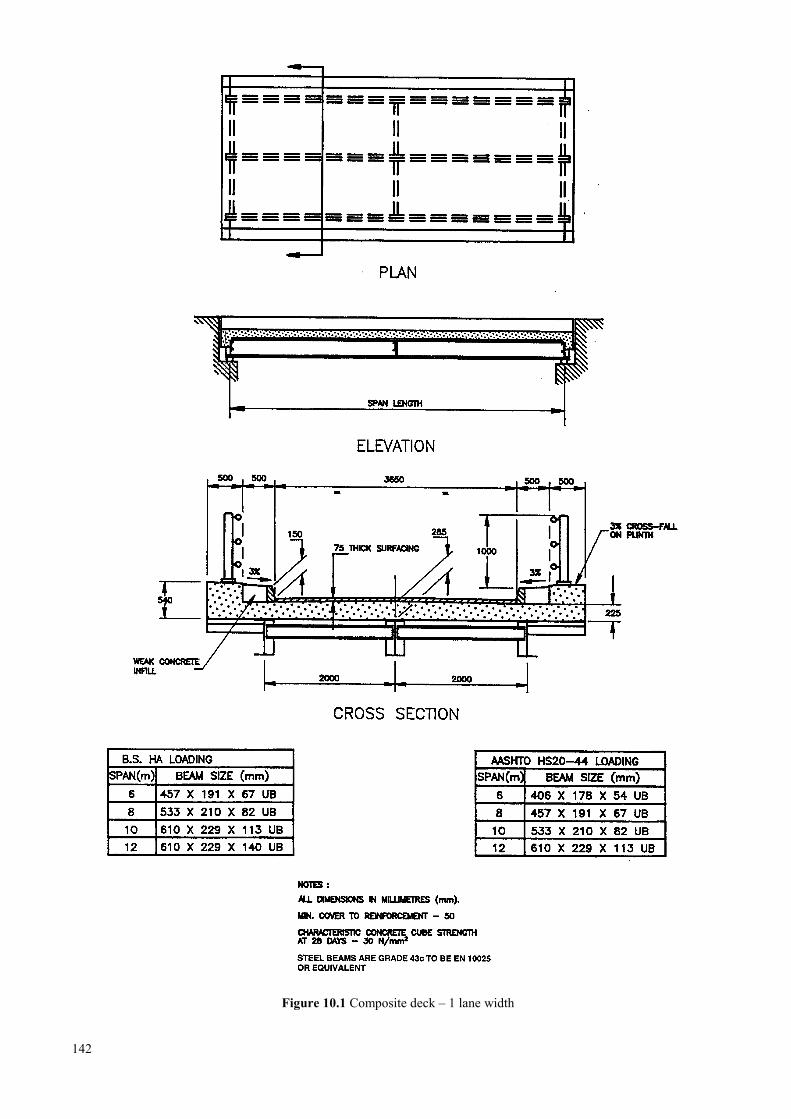
Figure 10.1 Composite deck – 1 lane width
142
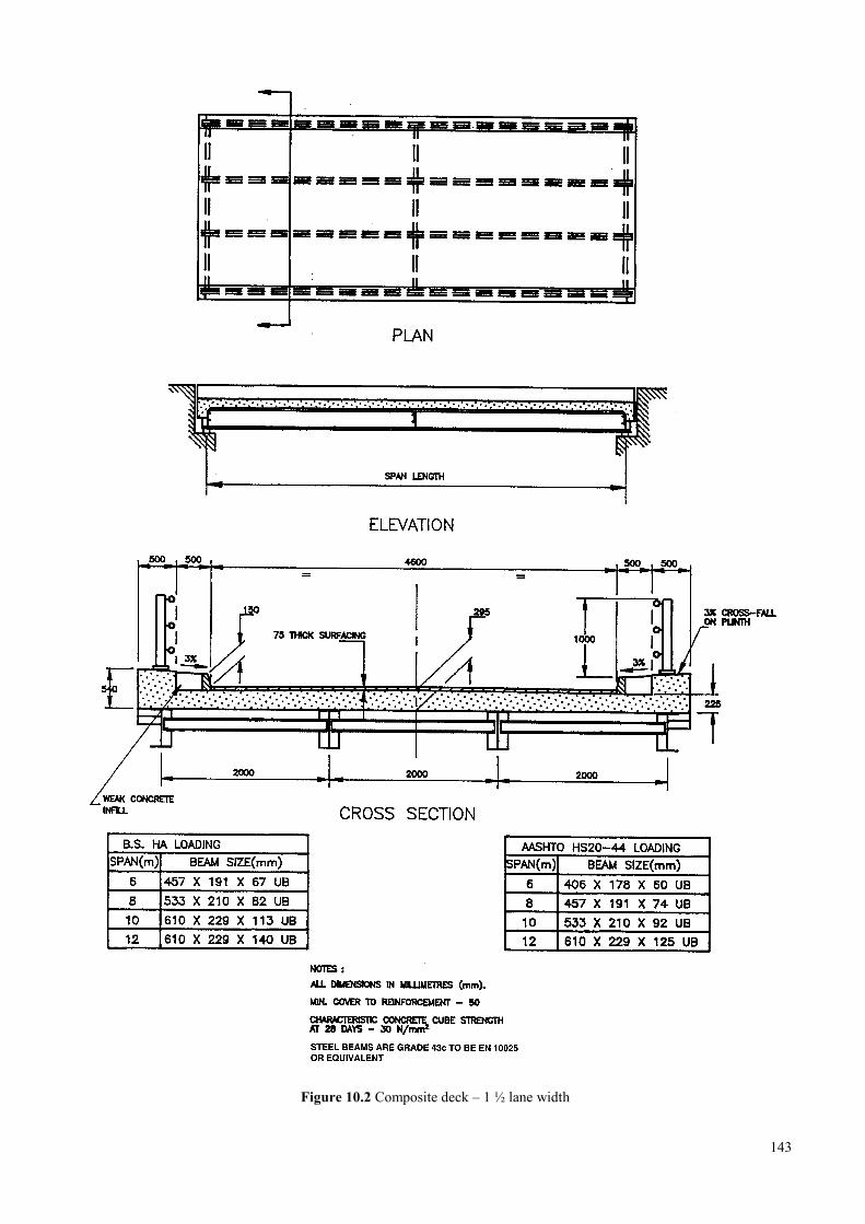
Figure 10.2 Composite deck – 1 ½ lane width
143
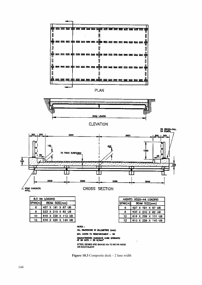
Figure 10.3 Composite deck – 2 lane width
144
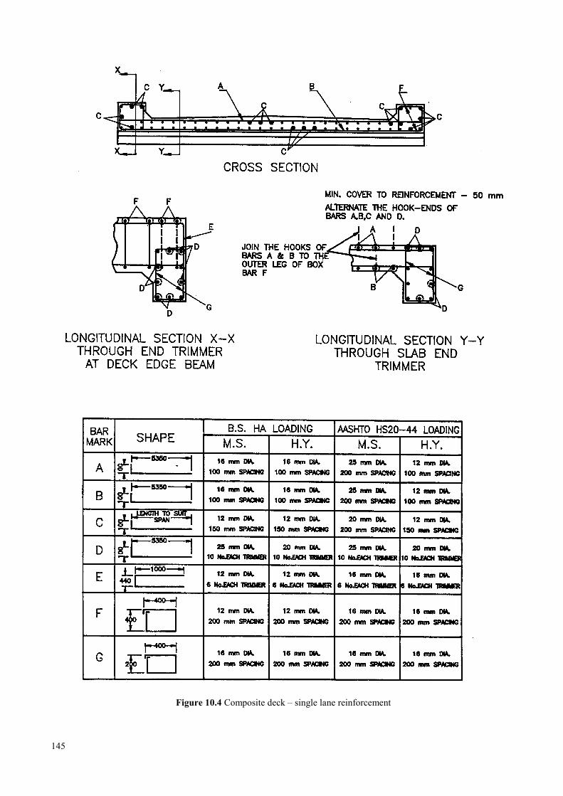
Figure 10.4 Composite deck – single lane reinforcement
145
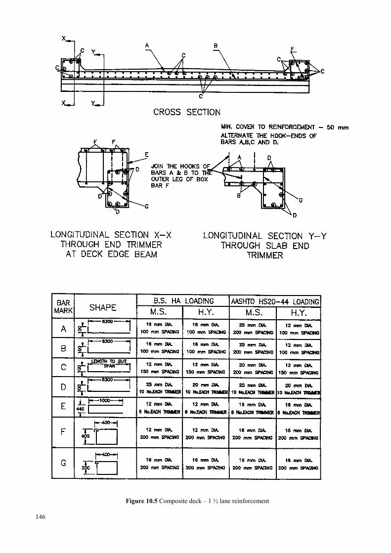
Figure 10.5 Composite deck – 1 ½ lane reinforcement
146
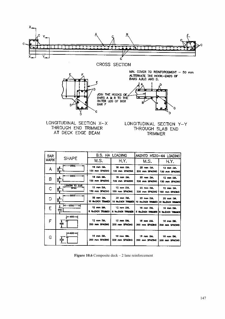
Figure 10.6 Composite deck – 2 lane reinforcement
147
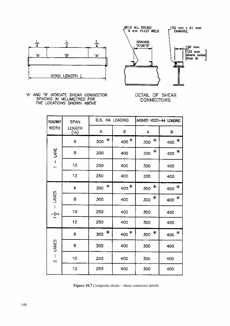
Figure 10.7 Composite decks – shear connector details
148
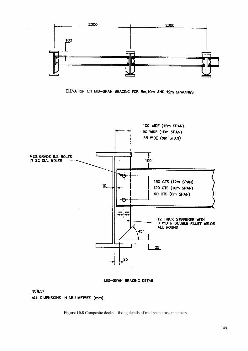
Figure 10.8 Composite decks – fixing details of mid-span cross members
149
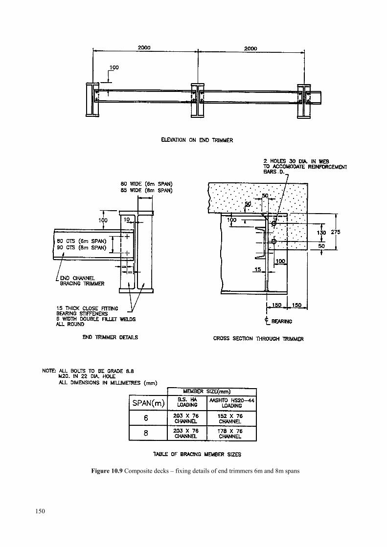
Figure 10.9 Composite decks – fixing details of end trimmers 6m and 8m spans
150
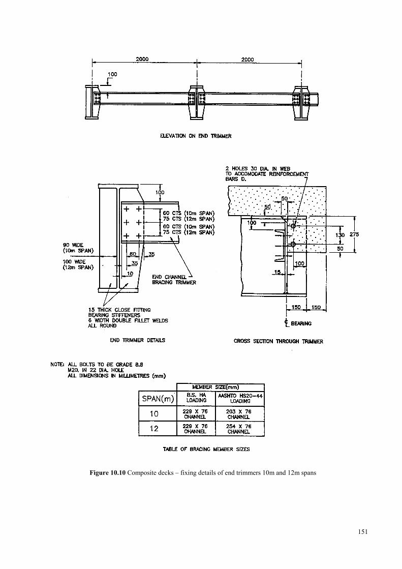
Figure 10.10 Composite decks – fixing details of end trimmers 10m and 12m spans
151

Figure 10.11 Composite decks – pier expansion joint and bearing details
152
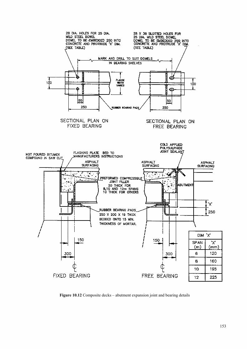
Figure 10.12 Composite decks – abutment expansion joint and bearing details
153

154

11 TIMBER SUPERSTRUCTURES
11.1 Log bridges ……………………………………………………………………………………………… 157
11.2 Sawn beam bridges ………………………………………………………………………………………158
11.3 Timber decking …………………………………………………………………………………………..158
11.4 Footways …………………………………………………………………………………………………158
11.5 Abutments ………………………………………………………………………………………………..158
11.6 References ………………………………………………………………………………………………. 158
11.7 Standard drawings and tables for timber superstructures ………………………………………………..160
155

156
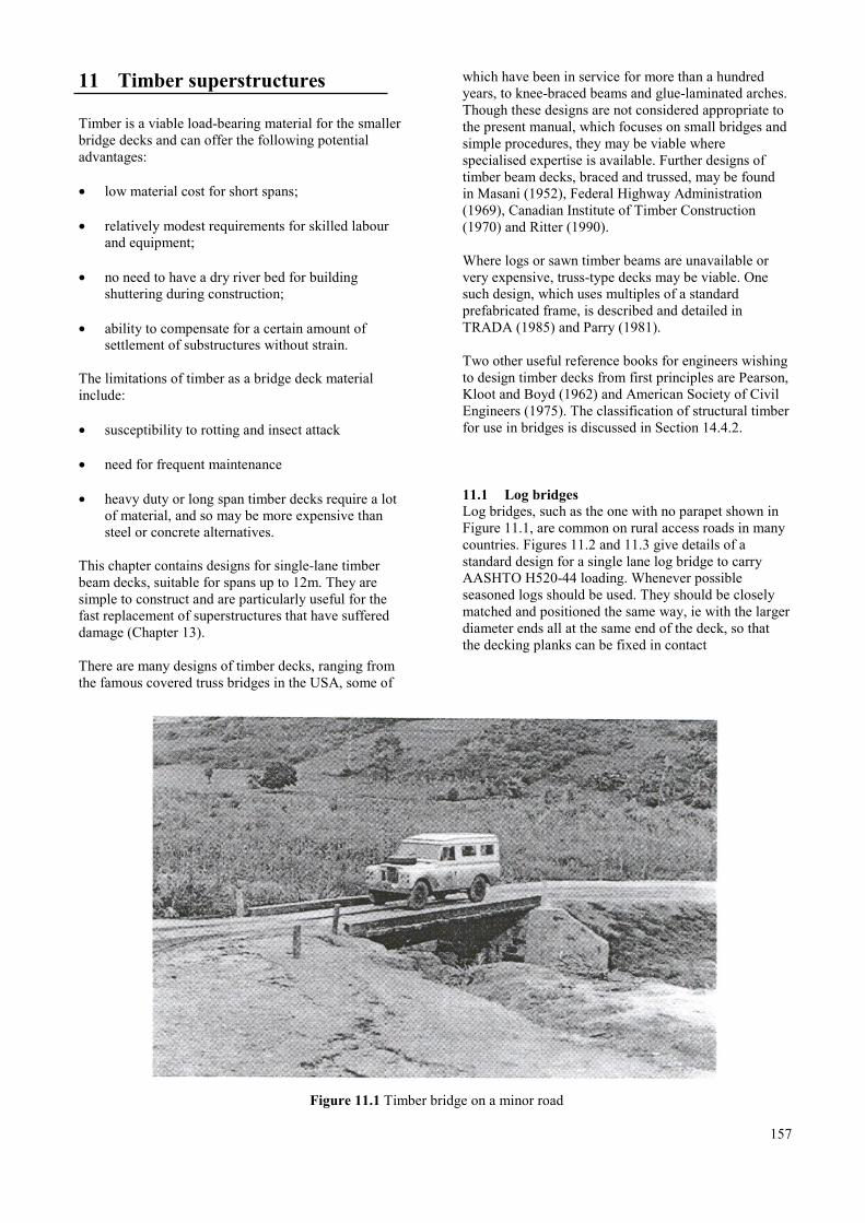
11 Timber superstructures
Timber is a viable load-bearing material for the smallerbridge decks and can offer the following potentialadvantages:
• low material cost for short spans;
• relatively modest requirements for skilled labourand equipment;
• no need to have a dry river bed for buildingshuttering during construction;
• ability to compensate for a certain amount ofsettlement of substructures without strain.
The limitations of timber as a bridge deck materialinclude:
• susceptibility to rotting and insect attack
• need for frequent maintenance
• heavy duty or long span timber decks require a lotof material, and so may be more expensive thansteel or concrete alternatives.
This chapter contains designs for single-lane timberbeam decks, suitable for spans up to 12m. They aresimple to construct and are particularly useful for thefast replacement of superstructures that have suffereddamage (Chapter 13).
There are many designs of timber decks, ranging fromthe famous covered truss bridges in the USA, some of
which have been in service for more than a hundredyears, to knee-braced beams and glue-laminated arches.Though these designs are not considered appropriate tothe present manual, which focuses on small bridges andsimple procedures, they may be viable wherespecialised expertise is available. Further designs oftimber beam decks, braced and trussed, may be foundin Masani (1952), Federal Highway Administration(1969), Canadian Institute of Timber Construction(1970) and Ritter (1990).
Where logs or sawn timber beams are unavailable orvery expensive, truss-type decks may be viable. Onesuch design, which uses multiples of a standardprefabricated frame, is described and detailed inTRADA (1985) and Parry (1981).
Two other useful reference books for engineers wishingto design timber decks from first principles are Pearson,Kloot and Boyd (1962) and American Society of CivilEngineers (1975). The classification of structural timberfor use in bridges is discussed in Section 14.4.2.
11.1 Log bridgesLog bridges, such as the one with no parapet shown inFigure 11.1, are common on rural access roads in manycountries. Figures 11.2 and 11.3 give details of astandard design for a single lane log bridge to carryAASHTO H520-44 loading. Whenever possibleseasoned logs should be used. They should be closelymatched and positioned the same way, ie with the largerdiameter ends all at the same end of the deck, so thatthe decking planks can be fixed in contact
Figure 11.1 Timber bridge on a minor road
157
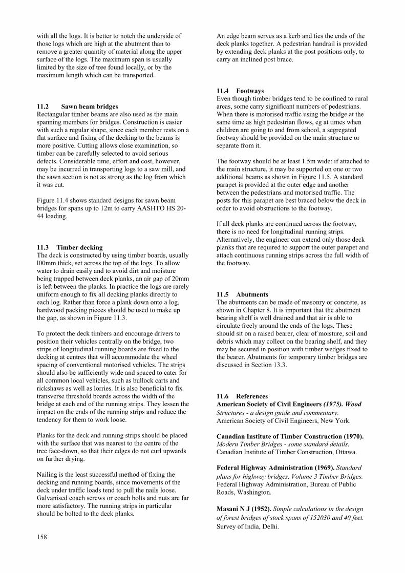
with all the logs. It is better to notch the underside ofthose logs which are high at the abutment than toremove a greater quantity of material along the uppersurface of the logs. The maximum span is usuallylimited by the size of tree found locally, or by themaximum length which can be transported.
11.2 Sawn beam bridgesRectangular timber beams are also used as the mainspanning members for bridges. Construction is easierwith such a regular shape, since each member rests on aflat surface and fixing of the decking to the beams ismore positive. Cutting allows close examination, sotimber can be carefully selected to avoid seriousdefects. Considerable time, effort and cost, however,may be incurred in transporting logs to a saw mill, andthe sawn section is not as strong as the log from whichit was cut.
Figure 11.4 shows standard designs for sawn beambridges for spans up to 12m to carry AASHTO HS 20-44 loading.
11.3 Timber deckingThe deck is constructed by using timber boards, usuallyl00mm thick, set across the top of the logs. To allowwater to drain easily and to avoid dirt and moisturebeing trapped between deck planks, an air gap of 20mmis left between the planks. In practice the logs are rarelyuniform enough to fix all decking planks directly toeach log. Rather than force a plank down onto a log,hardwood packing pieces should be used to make upthe gap, as shown in Figure 11.3.
To protect the deck timbers and encourage drivers toposition their vehicles centrally on the bridge, twostrips of longitudinal running boards are fixed to thedecking at centres that will accommodate the wheelspacing of conventional motorised vehicles. The stripsshould also be sufficiently wide and spaced to cater forall common local vehicles, such as bullock carts andrickshaws as well as lorries. It is also beneficial to fixtransverse threshold boards across the width of thebridge at each end of the running strips. They lessen theimpact on the ends of the running strips and reduce thetendency for them to work loose.
Planks for the deck and running strips should be placedwith the surface that was nearest to the centre of thetree face-down, so that their edges do not curl upwardson further drying.
Nailing is the least successful method of fixing thedecking and running boards, since movements of thedeck under traffic loads tend to pull the nails loose.Galvanised coach screws or coach bolts and nuts are farmore satisfactory. The running strips in particularshould be bolted to the deck planks.
158
An edge beam serves as a kerb and ties the ends of thedeck planks together. A pedestrian handrail is providedby extending deck planks at the post positions only, tocarry an inclined post brace.
11.4 FootwaysEven though timber bridges tend to be confined to ruralareas, some carry significant numbers of pedestrians.When there is motorised traffic using the bridge at thesame time as high pedestrian flows, eg at times whenchildren are going to and from school, a segregatedfootway should be provided on the main structure orseparate from it.
The footway should be at least 1.5m wide: if attached tothe main structure, it may be supported on one or twoadditional beams as shown in Figure 11.5. A standardparapet is provided at the outer edge and anotherbetween the pedestrians and motorised traffic. Theposts for this parapet are best braced below the deck inorder to avoid obstructions to the footway.
If all deck planks are continued across the footway,there is no need for longitudinal running strips.Alternatively, the engineer can extend only those deckplanks that are required to support the outer parapet andattach continuous running strips across the full width ofthe footway.
11.5 AbutmentsThe abutments can be made of masonry or concrete, asshown in Chapter 8. It is important that the abutmentbearing shelf is well drained and that air is able tocirculate freely around the ends of the logs. Theseshould sit on a raised bearer, clear of moisture, soil anddebris which may collect on the bearing shelf, and theymay be secured in position with timber wedges fixed tothe bearer. Abutments for temporary timber bridges arediscussed in Section 13.3.
11.6 ReferencesAmerican Society of Civil Engineers (1975). WoodStructures - a design guide and commentary.American Society of Civil Engineers, New York.
Canadian Institute of Timber Construction (1970).Modern Timber Bridges - some standard details.Canadian Institute of Timber Construction, Ottawa.
Federal Highway Administration (1969). Standardplans for highway bridges, Volume 3 Timber Bridges.Federal Highway Administration, Bureau of PublicRoads, Washington.
Masani N J (1952). Simple calculations in the designof forest bridges of stock spans of 152030 and 40 feet.Survey of India, Delhi.

Parry J D (1981). The Kenyan low cost modulartimber bridge. Laboratory Report LR970. TransportResearch Laboratory, Crowthorne.
Pearson R G, KIoot N H and Boyd J D (1962).Timber engineering design handbook. JacarandaPress Pty Ltd, second edition, Melbourne.
Ritter M A (1990). Timber Bridges - design,construction, inspection and maintenance. U SDepartment of Agriculture, Forest Service,Washington.
TRADA (1985). Prefabricated modular woodenbridges. Timber Research and DevelopmentAssociation, High Wycombe.
159

11.7 Standard drawings and tables for timber superstructures
Title Figure number
Log or timber beam bridge - longitudinal section …………………………………………………………………….11.2
Log bridge - cross section …………………………………………………………………………………………….11.3
Timber beam bridge - cross section …………………………………………………………………………………..11.4
Timber decks with segregated footway ……………………………………………………………………………….11.5
160
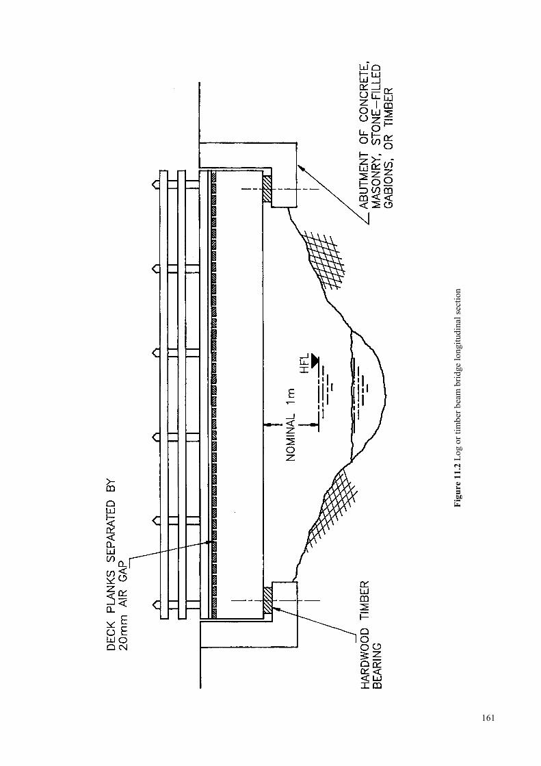
161
Figu
re 1
1.2
Log
or ti
mbe
r bea
m b
ridge
long
itudi
nal s
ectio
n
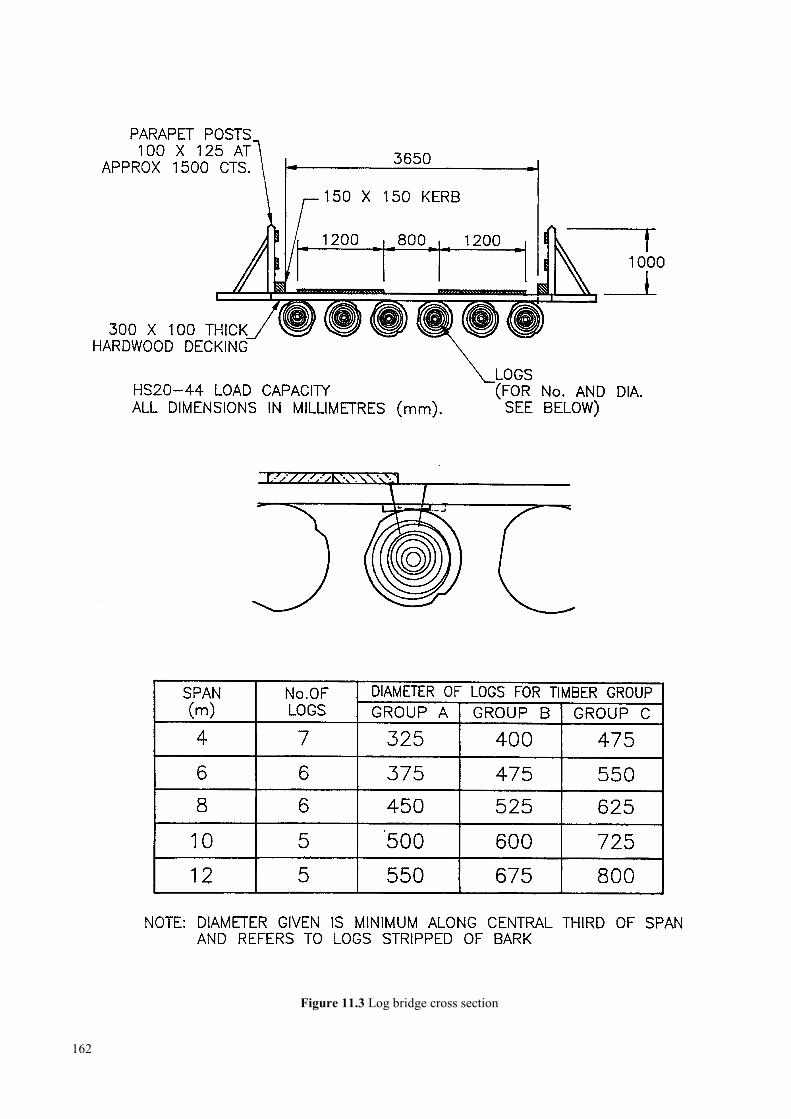
Figure 11.3 Log bridge cross section
162
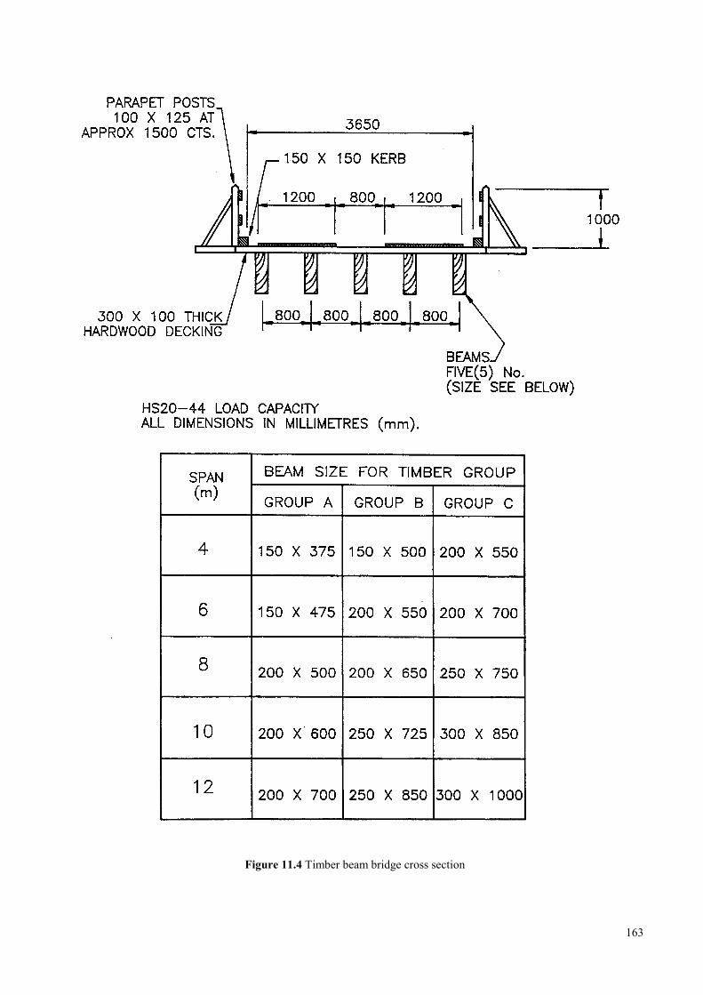
Figure 11.4 Timber beam bridge cross section
163
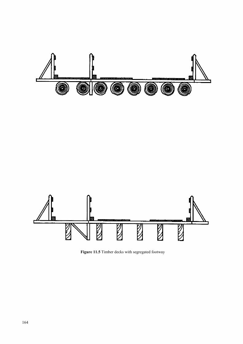
Figure 11.5 Timber decks with segregated footway
164
21 Culverts
12.1 Erosion control ……………………………………………………………………………………………167
12.2 Location and alignment …………………………………………………………………………………...167
12.3 Headwalls …………………………………………………………………………………………………170
12A Concrete pipe culverts …………………………………………………………………………………….170
12.5 Flexible steel culverts ………………………………………………………………………………….. 171
12.5.1 Foundations ……………………………………………………………………………………171
12.5.2 Backfill ………………………………………………………………………………………...171
12.5.3 Design ………………………………………………………………………………………… 171
12.5.4 Durability and corrosion protection …………………………………………………………...172
12.6 Reinforced concrete box culverts …………………………………………………………………………172
12.7 References ………………………………………………………………………………………………...172
12.8 Standard drawings and tables for concrete box culverts ………………………………………………….173
12.8.1 Index of drawings …………………………………………………………………………….. 173
12.8.2 Index of tables …………………………………………………………………………………181
165

166
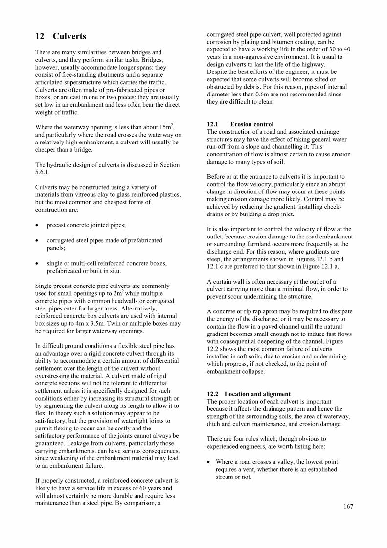
12 Culverts
There are many similarities between bridges andculverts, and they perform similar tasks. Bridges,however, usually accommodate longer spans: theyconsist of free-standing abutments and a separatearticulated superstructure which carries the traffic.Culverts are often made of pre-fabricated pipes orboxes, or are cast in one or two pieces: they are usuallyset low in an embankment and less often bear the directweight of traffic.
Where the waterway opening is less than about 15m2,and particularly where the road crosses the waterway ona relatively high embankment, a culvert will usually becheaper than a bridge.
The hydraulic design of culverts is discussed in Section5.6.1.
Culverts may be constructed using a variety ofmaterials from vitreous clay to glass reinforced plastics,but the most common and cheapest forms ofconstruction are:
• precast concrete jointed pipes;
• corrugated steel pipes made of prefabricatedpanels;
• single or multi-cell reinforced concrete boxes,prefabricated or built in situ.
Single precast concrete pipe culverts are commonlyused for small openings up to 2m2 while multipleconcrete pipes with common headwalls or corrugatedsteel pipes cater for larger areas. Alternatively,reinforced concrete box culverts are used with internalbox sizes up to 4m x 3.5m. Twin or multiple boxes maybe required for larger waterway openings.
In difficult ground conditions a flexible steel pipe hasan advantage over a rigid concrete culvert through itsability to accommodate a certain amount of differentialsettlement over the length of the culvert withoutoverstressing the material. A culvert made of rigidconcrete sections will not be tolerant to differentialsettlement unless it is specifically designed for suchconditions either by increasing its structural strength orby segmenting the culvert along its length to allow it toflex. In theory such a solution may appear to besatisfactory, but the provision of watertight joints topermit flexing to occur can be costly and thesatisfactory performance of the joints cannot always beguaranteed. Leakage from culverts, particularly thosecarrying embankments, can have serious consequences,since weakening of the embankment material may leadto an embankment failure.
If properly constructed, a reinforced concrete culvert islikely to have a service life in excess of 60 years andwill almost certainly be more durable and require lessmaintenance than a steel pipe. By comparison, a
corrugated steel pipe culvert, well protected againstcorrosion by plating and bitumen coating, can beexpected to have a working life in the order of 30 to 40years in a non-aggressive environment. It is usual todesign culverts to last the life of the highway.Despite the best efforts of the engineer, it must beexpected that some culverts will become silted orobstructed by debris. For this reason, pipes of internaldiameter less than 0.6m are not recommended sincethey are difficult to clean.
12.1 Erosion controlThe construction of a road and associated drainagestructures may have the effect of taking general waterrun-off from a slope and channelling it. Thisconcentration of flow is almost certain to cause erosiondamage to many types of soil.
Before or at the entrance to culverts it is important tocontrol the flow velocity, particularly since an abruptchange in direction of flow may occur at these pointsmaking erosion damage more likely. Control may beachieved by reducing the gradient, installing check-drains or by building a drop inlet.
It is also important to control the velocity of flow at theoutlet, because erosion damage to the road embankmentor surrounding farmland occurs more frequently at thedischarge end. For this reason, where gradients aresteep, the arrangements shown in Figures 12.1 b and12.1 c are preferred to that shown in Figure 12.1 a.
A curtain wall is often necessary at the outlet of aculvert carrying more than a minimal flow, in order toprevent scour undermining the structure.
A concrete or rip rap apron may be required to dissipatethe energy of the discharge, or it may be necessary tocontain the flow in a paved channel until the naturalgradient becomes small enough not to induce fast flowswith consequential deepening of the channel. Figure12.2 shows the most common failure of culvertsinstalled in soft soils, due to erosion and underminingwhich progress, if not checked, to the point ofembankment collapse.
12.2 Location and alignmentThe proper location of each culvert is importantbecause it affects the drainage pattern and hence thestrength of the surrounding soils, the area of waterway,ditch and culvert maintenance, and erosion damage.
There are four rules which, though obvious toexperienced engineers, are worth listing here:
• Where a road crosses a valley, the lowest pointrequires a vent, whether there is an establishedstream or not.
167
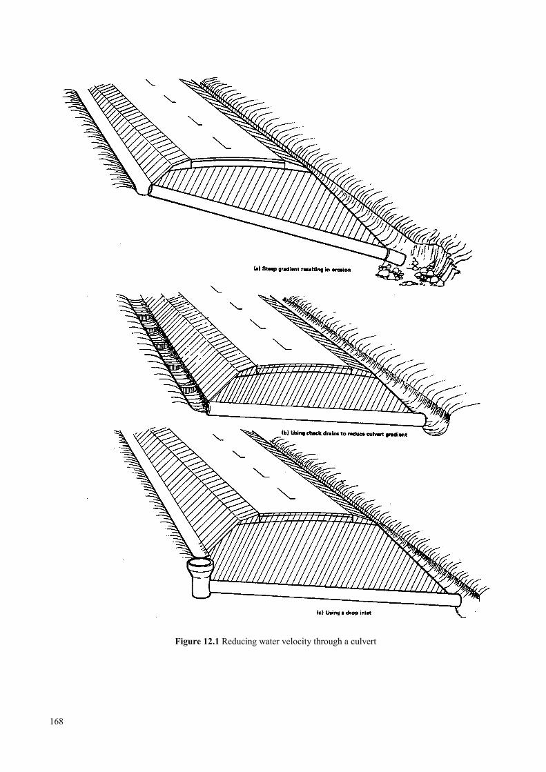
Figure 12.1 Reducing water velocity through a culvert
168
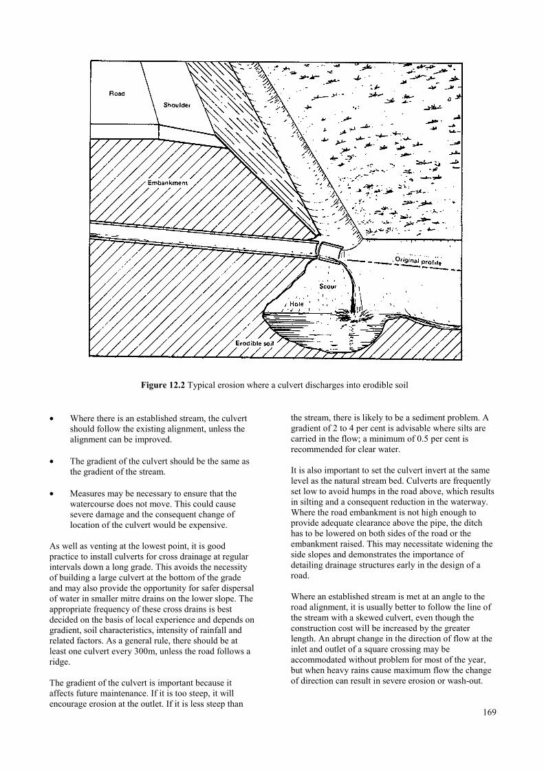
Figure 12.2 Typical erosion where a culvert discharges into erodible soil
• Where there is an established stream, the culvertshould follow the existing alignment, unless thealignment can be improved.
• The gradient of the culvert should be the same asthe gradient of the stream.
• Measures may be necessary to ensure that thewatercourse does not move. This could causesevere damage and the consequent change oflocation of the culvert would be expensive.
As well as venting at the lowest point, it is goodpractice to install culverts for cross drainage at regularintervals down a long grade. This avoids the necessityof building a large culvert at the bottom of the gradeand may also provide the opportunity for safer dispersalof water in smaller mitre drains on the lower slope. Theappropriate frequency of these cross drains is bestdecided on the basis of local experience and depends ongradient, soil characteristics, intensity of rainfall andrelated factors. As a general rule, there should be atleast one culvert every 300m, unless the road follows aridge.
The gradient of the culvert is important because itaffects future maintenance. If it is too steep, it willencourage erosion at the outlet. If it is less steep than
the stream, there is likely to be a sediment problem. Agradient of 2 to 4 per cent is advisable where silts arecarried in the flow; a minimum of 0.5 per cent isrecommended for clear water.
It is also important to set the culvert invert at the samelevel as the natural stream bed. Culverts are frequentlyset low to avoid humps in the road above, which resultsin silting and a consequent reduction in the waterway.Where the road embankment is not high enough toprovide adequate clearance above the pipe, the ditchhas to be lowered on both sides of the road or theembankment raised. This may necessitate widening theside slopes and demonstrates the importance ofdetailing drainage structures early in the design of aroad.
Where an established stream is met at an angle to theroad alignment, it is usually better to follow the line ofthe stream with a skewed culvert, even though theconstruction cost will be increased by the greaterlength. An abrupt change in the direction of flow at theinlet and outlet of a square crossing may beaccommodated without problem for most of the year,but when heavy rains cause maximum flow the changeof direction can result in severe erosion or wash-out.
169
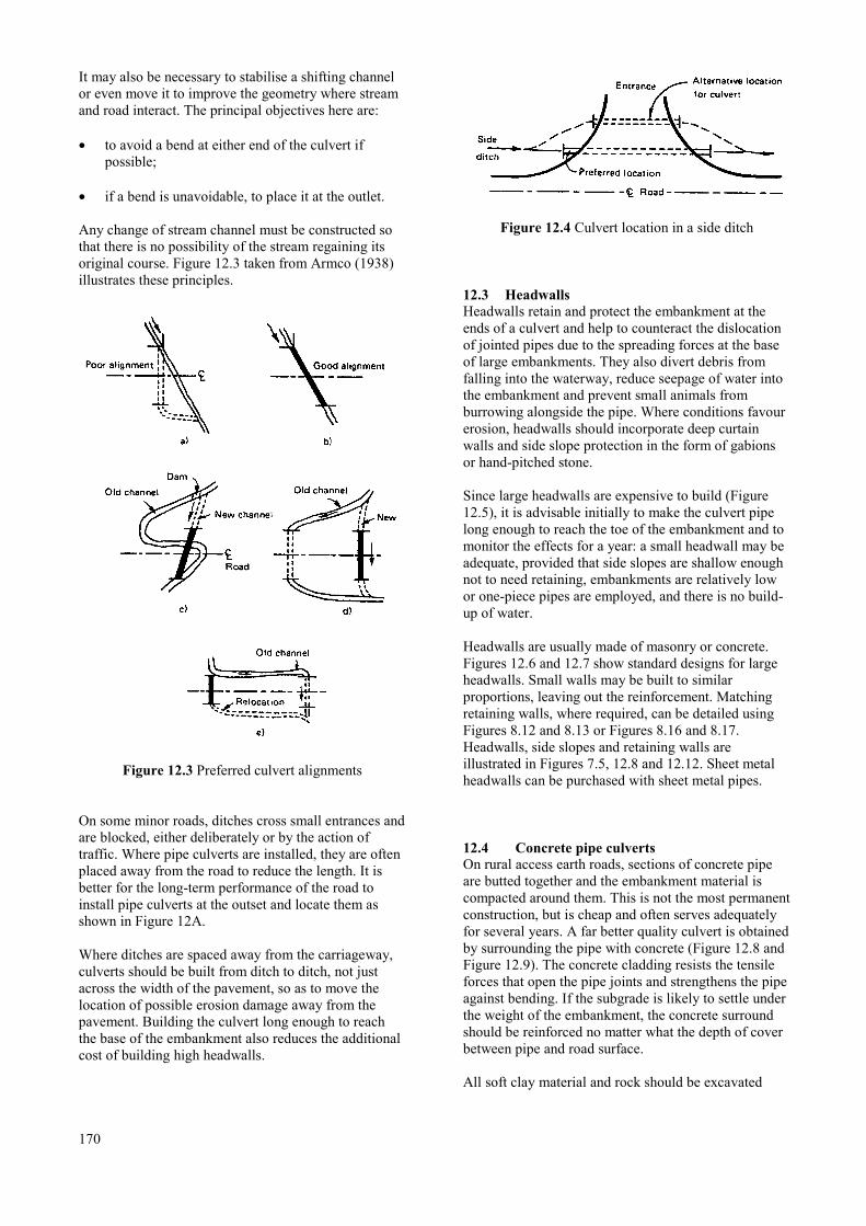
It may also be necessary to stabilise a shifting channelor even move it to improve the geometry where streamand road interact. The principal objectives here are:
• to avoid a bend at either end of the culvert ifpossible;
• if a bend is unavoidable, to place it at the outlet.
Any change of stream channel must be constructed sothat there is no possibility of the stream regaining itsoriginal course. Figure 12.3 taken from Armco (1938)illustrates these principles.
Figure 12.3 Preferred culvert alignments
On some minor roads, ditches cross small entrances andare blocked, either deliberately or by the action oftraffic. Where pipe culverts are installed, they are oftenplaced away from the road to reduce the length. It isbetter for the long-term performance of the road toinstall pipe culverts at the outset and locate them asshown in Figure 12A.
Where ditches are spaced away from the carriageway,culverts should be built from ditch to ditch, not justacross the width of the pavement, so as to move thelocation of possible erosion damage away from thepavement. Building the culvert long enough to reachthe base of the embankment also reduces the additionalcost of building high headwalls.
170
Figure 12.4 Culvert location in a side ditch
12.3 HeadwallsHeadwalls retain and protect the embankment at theends of a culvert and help to counteract the dislocationof jointed pipes due to the spreading forces at the baseof large embankments. They also divert debris fromfalling into the waterway, reduce seepage of water intothe embankment and prevent small animals fromburrowing alongside the pipe. Where conditions favourerosion, headwalls should incorporate deep curtainwalls and side slope protection in the form of gabionsor hand-pitched stone.
Since large headwalls are expensive to build (Figure12.5), it is advisable initially to make the culvert pipelong enough to reach the toe of the embankment and tomonitor the effects for a year: a small headwall may beadequate, provided that side slopes are shallow enoughnot to need retaining, embankments are relatively lowor one-piece pipes are employed, and there is no build-up of water.
Headwalls are usually made of masonry or concrete.Figures 12.6 and 12.7 show standard designs for largeheadwalls. Small walls may be built to similarproportions, leaving out the reinforcement. Matchingretaining walls, where required, can be detailed usingFigures 8.12 and 8.13 or Figures 8.16 and 8.17.Headwalls, side slopes and retaining walls areillustrated in Figures 7.5, 12.8 and 12.12. Sheet metalheadwalls can be purchased with sheet metal pipes.
12.4 Concrete pipe culvertsOn rural access earth roads, sections of concrete pipeare butted together and the embankment material iscompacted around them. This is not the most permanentconstruction, but is cheap and often serves adequatelyfor several years. A far better quality culvert is obtainedby surrounding the pipe with concrete (Figure 12.8 andFigure 12.9). The concrete cladding resists the tensileforces that open the pipe joints and strengthens the pipeagainst bending. If the subgrade is likely to settle underthe weight of the embankment, the concrete surroundshould be reinforced no matter what the depth of coverbetween pipe and road surface.
All soft clay material and rock should be excavated
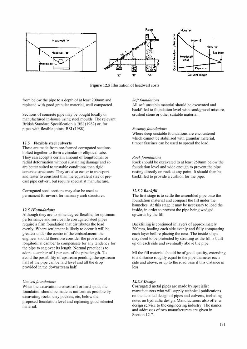
Figure 12.5 Illustration of headwall costs
from below the pipe to a depth of at least 200mm andreplaced with good granular material, well compacted.
Sections of concrete pipe may be bought locally ormanufactured in-house using steel moulds. The relevantBritish Standard Specification is BSI (1982) or, forpipes with flexible joints, BSI (1988).
12.5 Flexible steel culvertsThese are made from pre-formed corrugated sectionsbolted together to form a circular or elliptical tube.They can accept a certain amount of longitudinal orradial deformation without sustaining damage and soare better suited to unstable conditions than rigidconcrete structures. They are also easier to transportand faster to construct than the equivalent size of pre-cast pipe culvert, but require specialist manufacture.
Corrugated steel sections may also be used aspermanent formwork for masonry arch structures.
12.5.1FoundationsAlthough they are to some degree flexible, for optimumperformance and service life corrugated steel pipesrequire a firm foundation that distributes the loadevenly. Where settlement is likely to occur it will begreatest under the centre of the embankment: theengineer should therefore consider the provision of alongitudinal camber to compensate for any tendency forthe pipe to sag over its length. Normal practice is toadopt a camber of 1 per cent of the pipe length. Toavoid the possibility of upstream ponding, the upstreamhalf of the pipe can be laid level and all the dropprovided in the downstream half.
Uneven foundationsWhen the excavation crosses soft or hard spots, thefoundation should be made as uniform as possible byexcavating rocks, clay pockets, etc, below theproposed foundation level and replacing good selectedmaterial.
Soft foundationsAll soft unstable material should be excavated andbackfilled to foundation level with sand/gravel mixture,crushed stone or other suitable material.
Swampy foundationsWhere deep unstable foundations are encounteredwhich cannot be stabilised with granular material,timber fascines can be used to spread the load.
Rock foundationsRock should be excavated to at least 250mm below thefoundation level and wide enough to prevent the piperesting directly on rock at any point. It should then bebackfilled to provide a cushion for the pipe.
12.5.2 BackfillThe first stage is to settle the assembled pipe onto thefoundation material and compact the fill under thehaunches. At this stage it may be necessary to load theinside, in order to prevent the pipe being wedgedupwards by the fill.
Backfilling is continued in layers of approximately200mm, loading each side evenly and fully compactingeach layer before placing the next. The inside shapemay need to be protected by strutting as the fill is builtup on each side and eventually above the pipe.
Ml the fill material should be of good quality, extendingto a distance roughly equal to the pipe diameter eachside and above, or up to the road base if this distance isless.
12.5.3 DesignCorrugated metal pipes are made by specialistmanufacturers who will supply technical publicationson the detailed design of pipes and culverts, includingnotes on hydraulic design. Manufacturers also offer adesign service to the engineering industry. The namesand addresses of two manufacturers are given inSection 12.7.
171
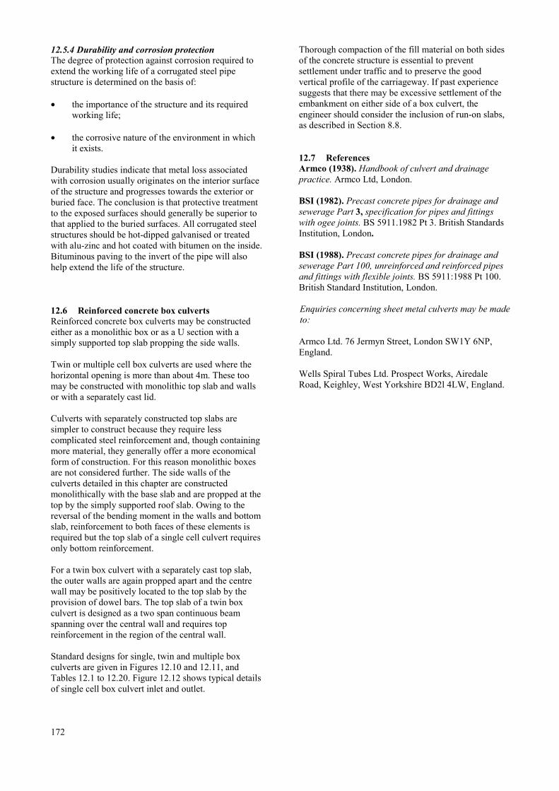
12.5.4 Durability and corrosion protectionThe degree of protection against corrosion required toextend the working life of a corrugated steel pipestructure is determined on the basis of:
• the importance of the structure and its requiredworking life;
• the corrosive nature of the environment in whichit exists.
Durability studies indicate that metal loss associatedwith corrosion usually originates on the interior surfaceof the structure and progresses towards the exterior orburied face. The conclusion is that protective treatmentto the exposed surfaces should generally be superior tothat applied to the buried surfaces. All corrugated steelstructures should be hot-dipped galvanised or treatedwith alu-zinc and hot coated with bitumen on the inside.Bituminous paving to the invert of the pipe will alsohelp extend the life of the structure.
12.6 Reinforced concrete box culvertsReinforced concrete box culverts may be constructedeither as a monolithic box or as a U section with asimply supported top slab propping the side walls.
Twin or multiple cell box culverts are used where thehorizontal opening is more than about 4m. These toomay be constructed with monolithic top slab and wallsor with a separately cast lid.
Culverts with separately constructed top slabs aresimpler to construct because they require lesscomplicated steel reinforcement and, though containingmore material, they generally offer a more economicalform of construction. For this reason monolithic boxesare not considered further. The side walls of theculverts detailed in this chapter are constructedmonolithically with the base slab and are propped at thetop by the simply supported roof slab. Owing to thereversal of the bending moment in the walls and bottomslab, reinforcement to both faces of these elements isrequired but the top slab of a single cell culvert requiresonly bottom reinforcement.
For a twin box culvert with a separately cast top slab,the outer walls are again propped apart and the centrewall may be positively located to the top slab by theprovision of dowel bars. The top slab of a twin boxculvert is designed as a two span continuous beamspanning over the central wall and requires topreinforcement in the region of the central wall.
Standard designs for single, twin and multiple boxculverts are given in Figures 12.10 and 12.11, andTables 12.1 to 12.20. Figure 12.12 shows typical detailsof single cell box culvert inlet and outlet.
172
Thorough compaction of the fill material on both sidesof the concrete structure is essential to preventsettlement under traffic and to preserve the goodvertical profile of the carriageway. If past experiencesuggests that there may be excessive settlement of theembankment on either side of a box culvert, theengineer should consider the inclusion of run-on slabs,as described in Section 8.8.
12.7 ReferencesArmco (1938). Handbook of culvert and drainagepractice. Armco Ltd, London.
BSI (1982). Precast concrete pipes for drainage andsewerage Part 3, specification for pipes and fittingswith ogee joints. BS 5911.1982 Pt 3. British StandardsInstitution, London.
BSI (1988). Precast concrete pipes for drainage andsewerage Part 100, unreinforced and reinforced pipesand fittings with flexible joints. BS 5911:1988 Pt 100.British Standard Institution, London.
Enquiries concerning sheet metal culverts may be madeto:
Armco Ltd. 76 Jermyn Street, London SW1Y 6NP,England.
Wells Spiral Tubes Ltd. Prospect Works, AiredaleRoad, Keighley, West Yorkshire BD2l 4LW, England.

12.8 Standard drawings and tables for concrete box culverts
12.8.1 Index of drawings
Title Figure numbers
Mass concrete headwall for a high embankment ……………………………………………………………………..12.6
Reinforced concrete headwall for a high embankment ……………………………………………………………….12.7
Typical details of a pipe culvert with headwalls ……………………………………………………………………...12.8
Details of concrete pipe surrounds ……………………………………………………………………………………12.9
Single box culvert - section ………………………………………………………………………………………….12.10
Twin box culvert - section ………………………………………………………………………………………….. 12.11
Typical details of single cell box culvert inlet and outlet …………………………………………………………...12.12
173

Figure 12.6 Mass concrete headwall for a high embankment
174
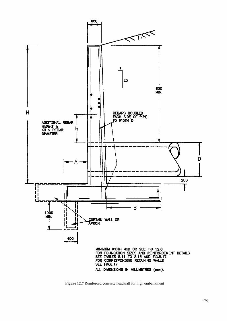
Figure 12.7 Reinforced concrete headwall for high embankment
175
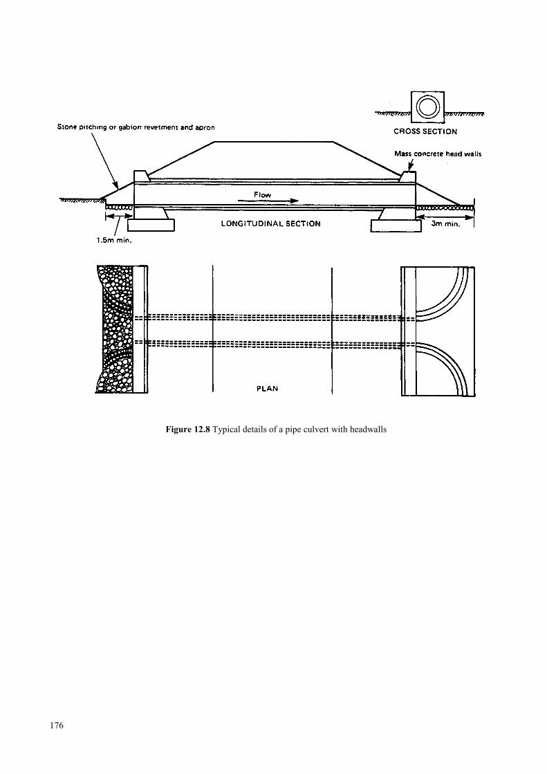
Figure 12.8 Typical details of a pipe culvert with headwalls
176
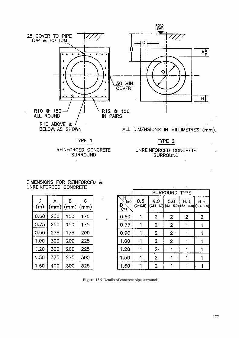
Figure 12.9 Details of concrete pipe surrounds
177
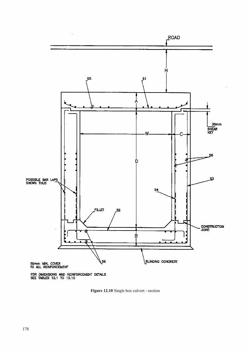
Figure 12.10 Single box culvert - section
178

179
Figu
re 1
2.11
Tw
in b
ox c
ulve
rt - s
ectio
n
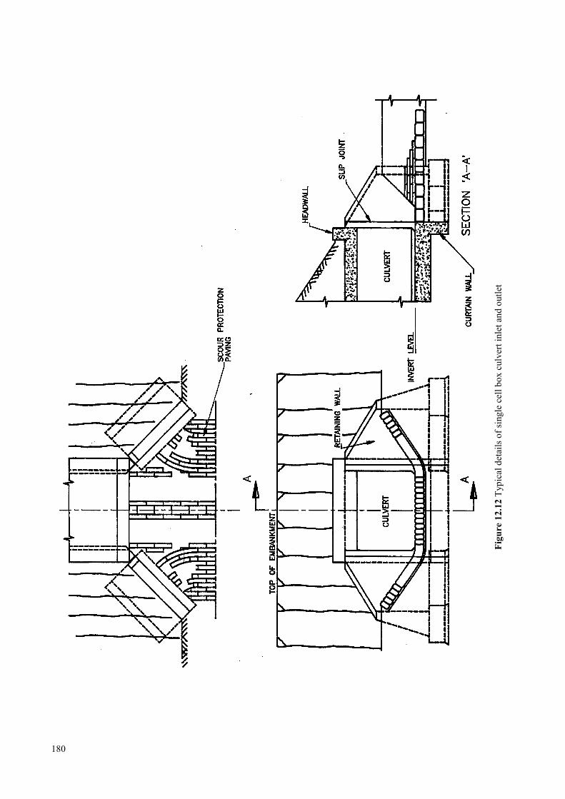
180
Figu
re 1
2.12
Typ
ical
det
ails
of s
ingl
e ce
ll bo
x cu
lver
t inl
et a
nd o
utle
t

12.8.2 Index of tables
Title Height of fill Table number
Single box culvert - high yield steel H = 0.5m …………………………………………………….12.1
Single box culvert - high yield steel H = 1.0m …………………………………………………….12.2
Single box culvert - high yield steel H = 2.0m …………………………………………………….12.3
Single box culvert - high yield steel H = 4.0m …………………………………………………….12.4
Single box culvert - high yield steel H = 6.0m …………………………………………………….12.5
Single box culvert - mild steel H = 0.5m …………………………………………………….12.6
Single box culvert - mild steel H = l.0m ……………………………………………………..12.7
Single box culvert - mild steel H = 2.0m …………………………………………………….12.8
Single box culvert - mild steel H = 4.0m …………………………………………………….12.9
Single box culvert - mild steel H = 6.0m …………………………………………………...12.10
Twin box culvert - high yield steel H = 0.5m …………………………………………………...12.11
Twin box culvert - high yield steel H = l.0m ……………………………………………………12.12
Twin box culvert - high yield steel H = 2.0m …………………………………………………...12.13
Twin box culvert - high yield steel H = 4.0m …………………………………………………...12.14
Twin box culvert - high yield steel H = 6.0m …………………………………………………...12.15
Twin box culvert - mild steel H = 0.5m …………………………………………………...12.16
Twin box culvert - mild steel H = l.0m ……………………………………………………12.17
Twin box culvert - mild steel H = 2.0m …………………………………………………...12.18
Twin box culvert - mild steel H = 4.0m …………………………………………………...12.19
Twin box culvert - mild steel H = 6.0m …………………………………………………...12.20
181
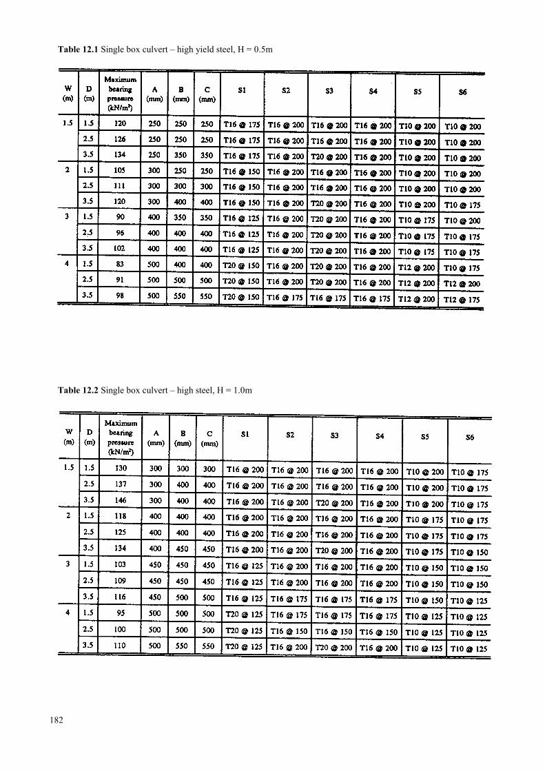
Table 12.1 Single box culvert – high yield steel, H = 0.5m
Table 12.2 Single box culvert – high steel, H = 1.0m
182
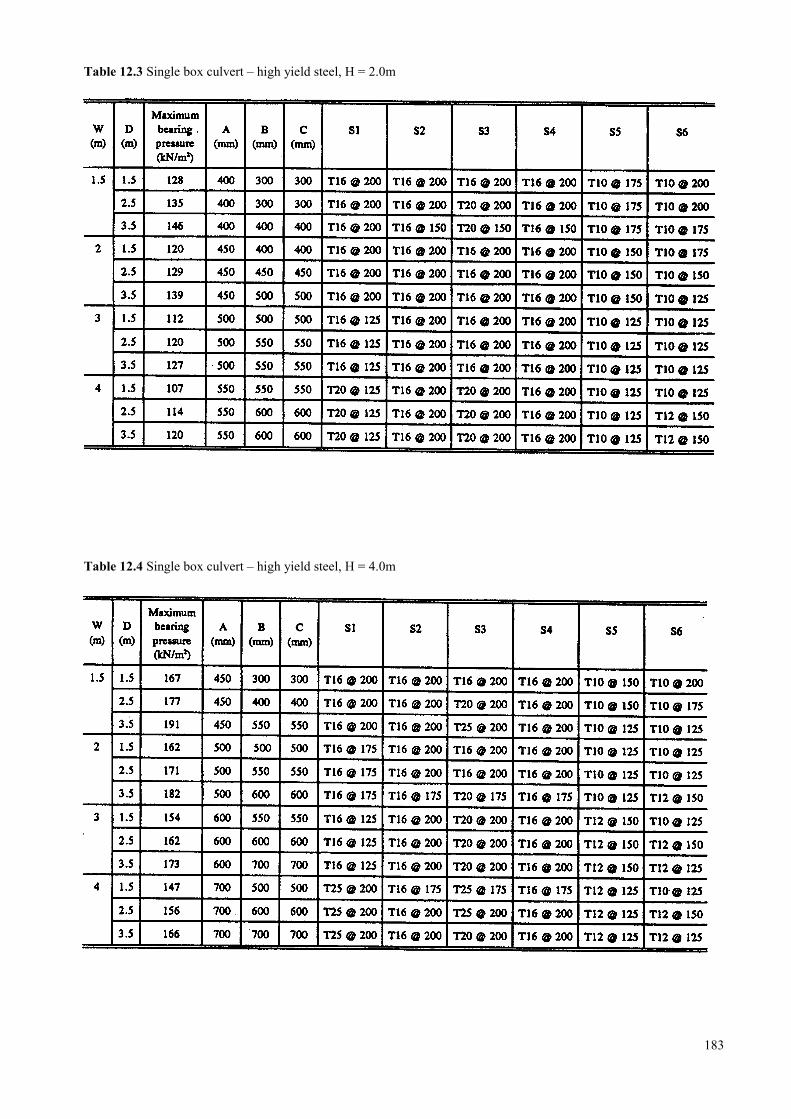
Table 12.3 Single box culvert – high yield steel, H = 2.0m
Table 12.4 Single box culvert – high yield steel, H = 4.0m
183
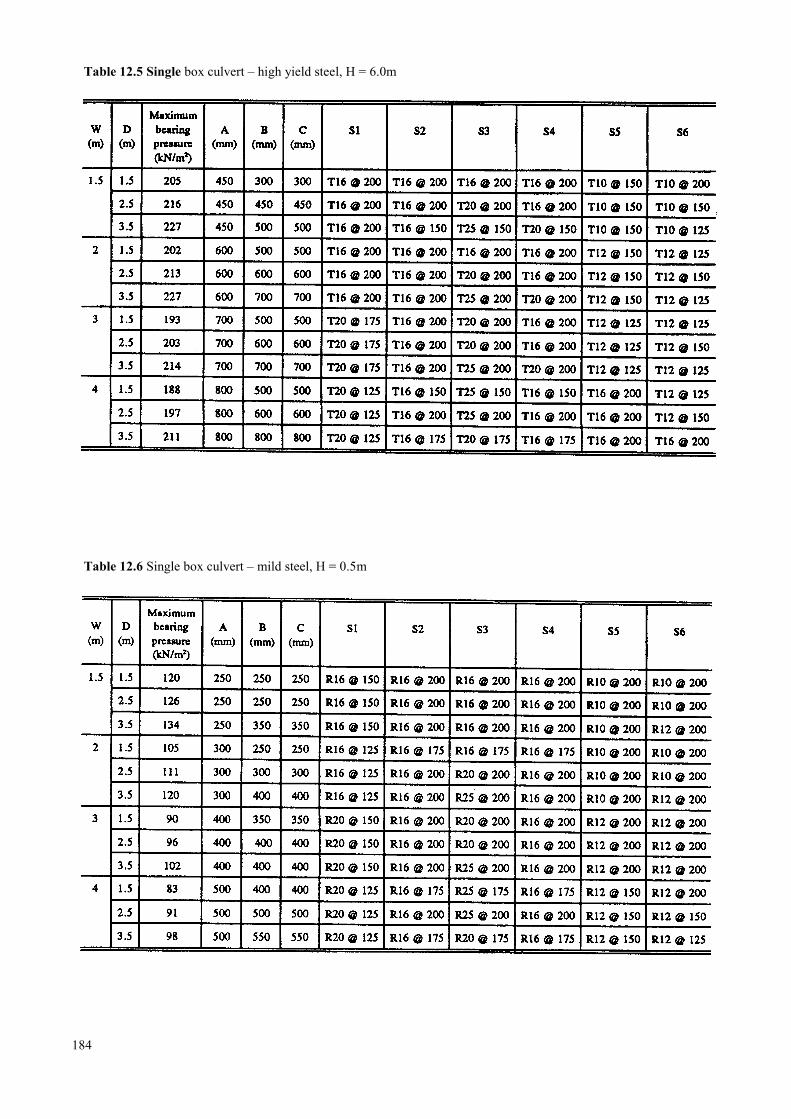
Table 12.5 Single box culvert – high yield steel, H = 6.0m
Table 12.6 Single box culvert – mild steel, H = 0.5m
184
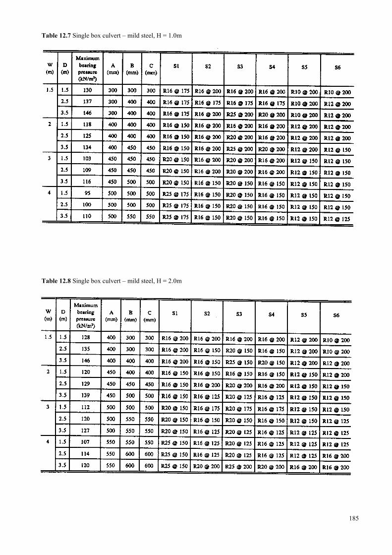
Table 12.7 Single box culvert – mild steel, H = 1.0m
Table 12.8 Single box culvert – mild steel, H = 2.0m
185
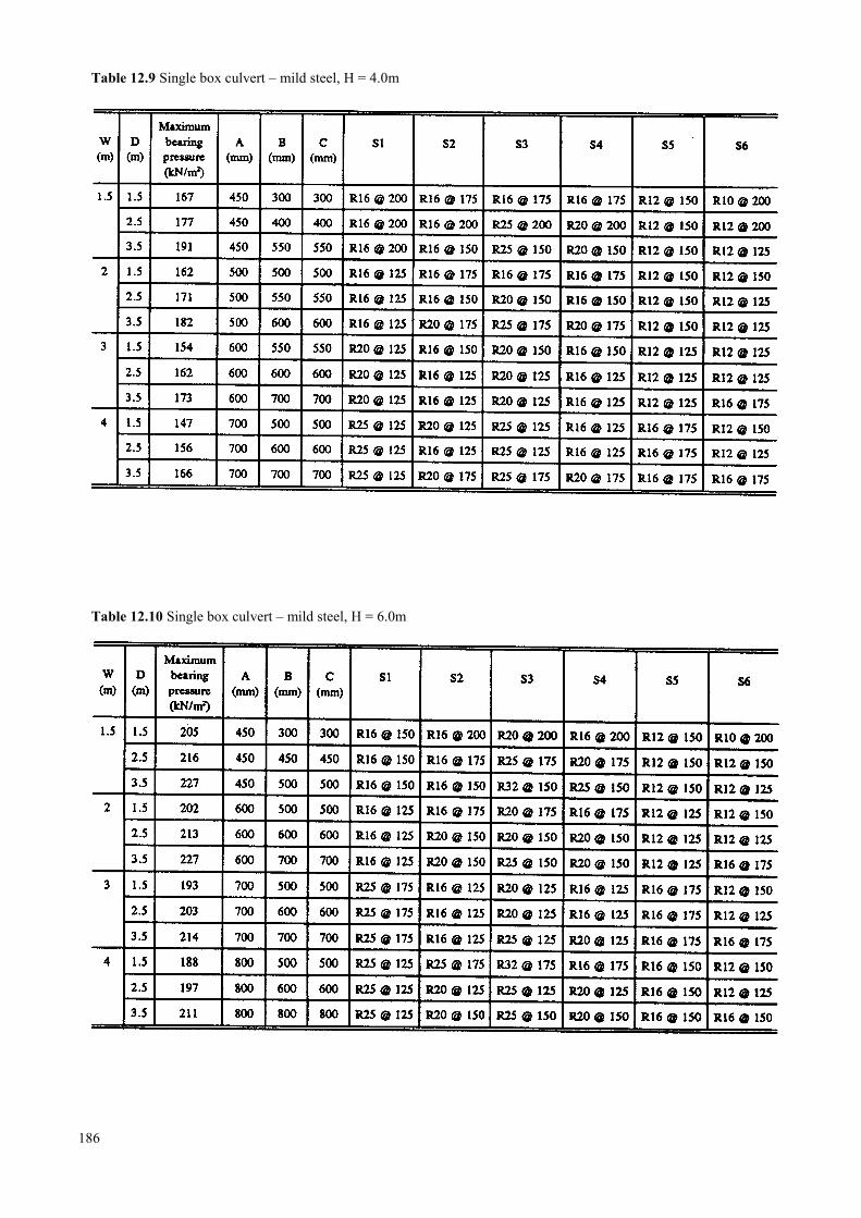
Table 12.9 Single box culvert – mild steel, H = 4.0m
Table 12.10 Single box culvert – mild steel, H = 6.0m
186
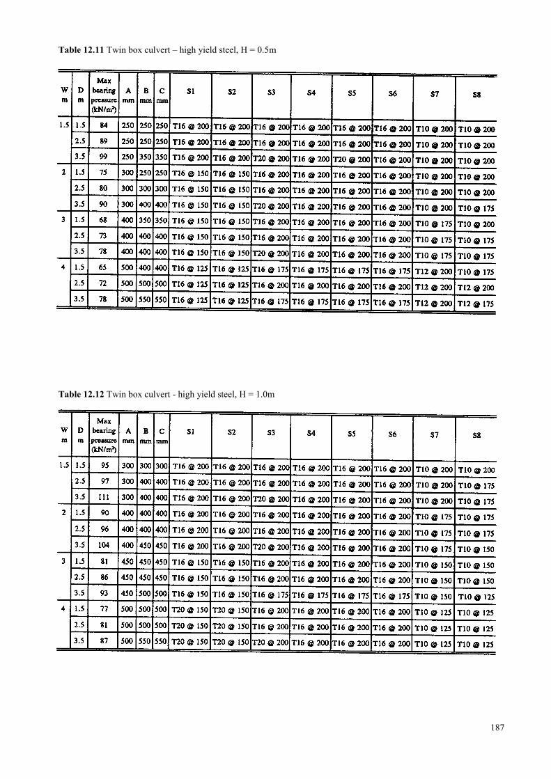
Table 12.11 Twin box culvert – high yield steel, H = 0.5m
Table 12.12 Twin box culvert - high yield steel, H = 1.0m
187
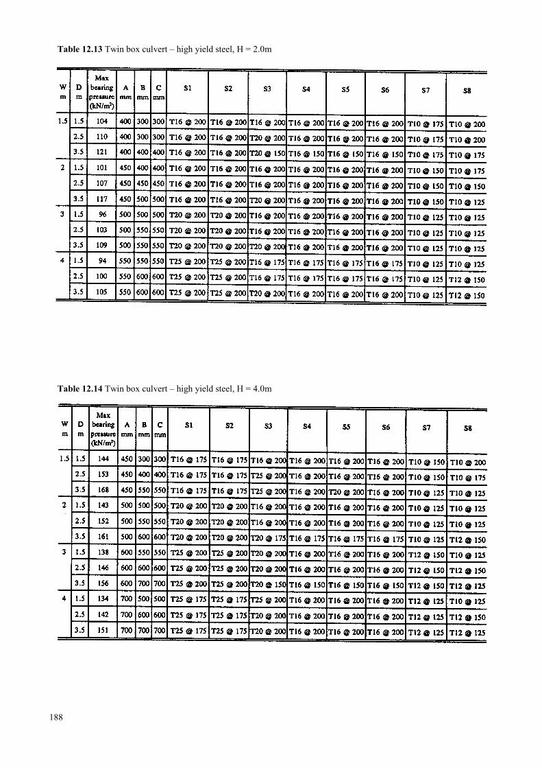
Table 12.13 Twin box culvert – high yield steel, H = 2.0m
Table 12.14 Twin box culvert – high yield steel, H = 4.0m
188
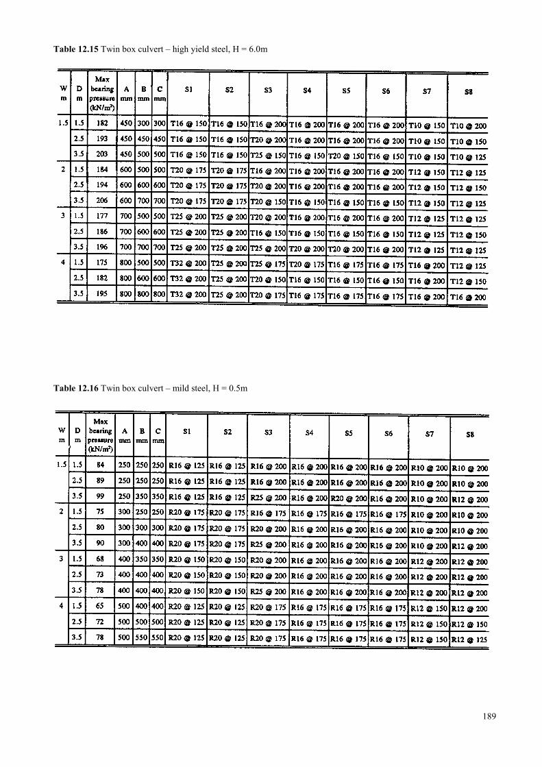
Table 12.15 Twin box culvert – high yield steel, H = 6.0m
Table 12.16 Twin box culvert – mild steel, H = 0.5m
189
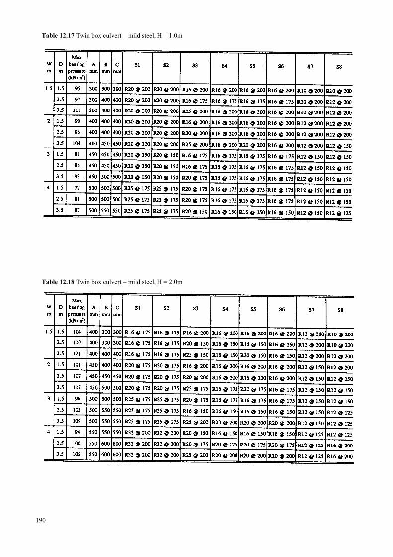
Table 12.17 Twin box culvert – mild steel, H = 1.0m
Table 12.18 Twin box culvert – mild steel, H = 2.0m
190
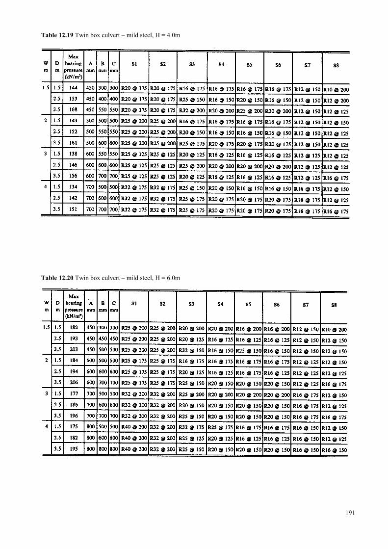
Table 12.19 Twin box culvert – mild steel, H = 4.0m
Table 12.20 Twin box culvert – mild steel, H = 6.0m
191

192
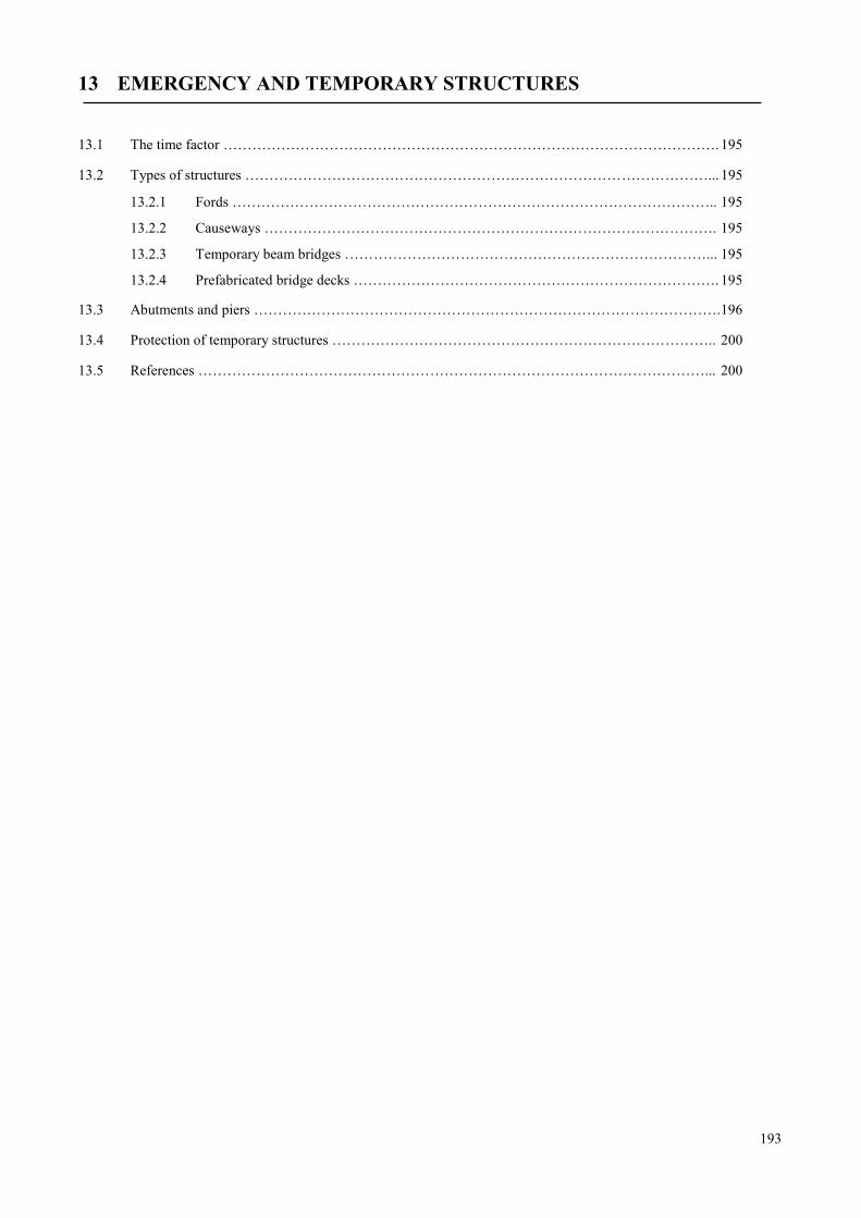
13 EMERGENCY AND TEMPORARY STRUCTURES
13.1 The time factor …………………………………………………………………………………………. 195
13.2 Types of structures ……………………………………………………………………………………... 195
13.2.1 Fords ……………………………………………………………………………………….. 195
13.2.2 Causeways …………………………………………………………………………………. 195
13.2.3 Temporary beam bridges …………………………………………………………………... 195
13.2.4 Prefabricated bridge decks …………………………………………………………………. 195
13.3 Abutments and piers …………………………………………………………………………………….196
13.4 Protection of temporary structures …………………………………………………………………….. 200
13.5 References ……………………………………………………………………………………………... 200
193

194
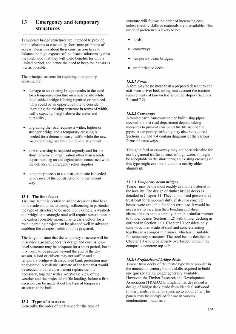
13 Emergency and temporarystructures
Temporary bridge structures are intended to providerapid solutions to essentially short-term problems ofaccess. Decisions about their construction have tobalance the high expense of the fastest solutions againstthe likelihood that they will yield benefits for only alimited period, and hence the need to keep their costs aslow as possible.
The principal reasons for requiring a temporarycrossing are:
• damage to an existing bridge results in the needfor a temporary structure on a nearby site whilethe disabled bridge is being repaired or replaced.(This could be an opportune time to considerupgrading the existing structure in terms of width,traffic capacity, height above the water anddurability.)
• upgrading the road requires a wider, higher orstronger bridge and a temporary crossing isneeded for a detour to carry traffic while the newroad and bridge are built on the old alignment.
• a river crossing is required urgently and for theshort term by an organisation other than a roadsdepartment, eg an aid organisation concerned withthe delivery of emergency relief supplies.
• temporary access to a construction site is neededin advance of the construction of a permanentway.
13.1 The time factorThe time factor is central to all the decisions that haveto be made about the crossing, influencing in particularthe type of structure to be used. For example, a washed-out bridge on a strategic road will require substitution atthe earliest possible moment, whereas a detour for aroad upgrading project can be planned well in advance,enabling the cheapest solution to be prepared.
The length of time that the temporary structure will bein service also influences its design and cost. A low-level structure may be adequate for a short period, but ifit is likely to be needed beyond the end of the dryseason, a lord or culvert may not suffice and atemporary bridge with associated bank protection maybe required. A realistic estimate of the time that wouldbe needed to build a permanent replacement isnecessary, together with a worst-case view of theweather and the projected traffic loading, before a firmdecision can be made about the type of temporarystructure to be built.
13.2 Types of structuresGenerally, the order of preference for the type of
structure will follow the order of increasing cost,unless specific skills or materials are unavailable. Thisorder of preference is likely to be:
•••• fords;
• causeways;
•••• temporary beam bridges;
•••• prefabricated decks.
13.2.1 FordsA ford may be no more than a prepared descent to andexit from a river bed, taking into account the tractionrequirements of known traffic on the slopes (Sections7.1 and 7.2).
13.2.2 CausewaysA vented earth causeway can be built using pipesstocked in most road department depots, takingmeasures to prevent erosion of the fill around thepipes. A temporary surfacing may also be required.Sections 7.3 and 7.4 contain diagrams of the variousforms of causeways.
Though a ford or causeway may not be serviceable foruse by general traffic at times of high water, it mightbe acceptable in the short term; an existing crossing ofthis type might even be found on a nearby olderalignment.
13.2.3 Temporary beam bridgesTimber may be the most readily available material inthe locality. The design of timber bridge decks isdetailed in Chapter 11. They do not need preservativetreatment for temporary duty. if steel or concretebeams were available for short-term use, it would benecessary to ascertain their bending and shearcharacteristics and to employ them in a similar mannerto timber beams (Section 11.2) with timber decking asoutlined in Section 11.3. Chapter 10 considers onlysuperstructures made of steel and concrete actingtogether in a composite manner, which is unsuitablefor temporary structures. The steel beams detailed inChapter 10 would be grossly overloaded without thecomposite concrete top slab.
13.2.4 Prefabricated bridge decksTimber truss decks of the trestle type were popular inthe nineteenth century but the skills required to buildone quickly are no longer generally available.However, the Timber Research and DevelopmentAssociation (TRADA) in England has developed adesign of bridge deck made from identical softwoodtimber panels, viable for spans up to about 24m. Thepanels may be stockpiled for use in variouscombinations, much as a
195
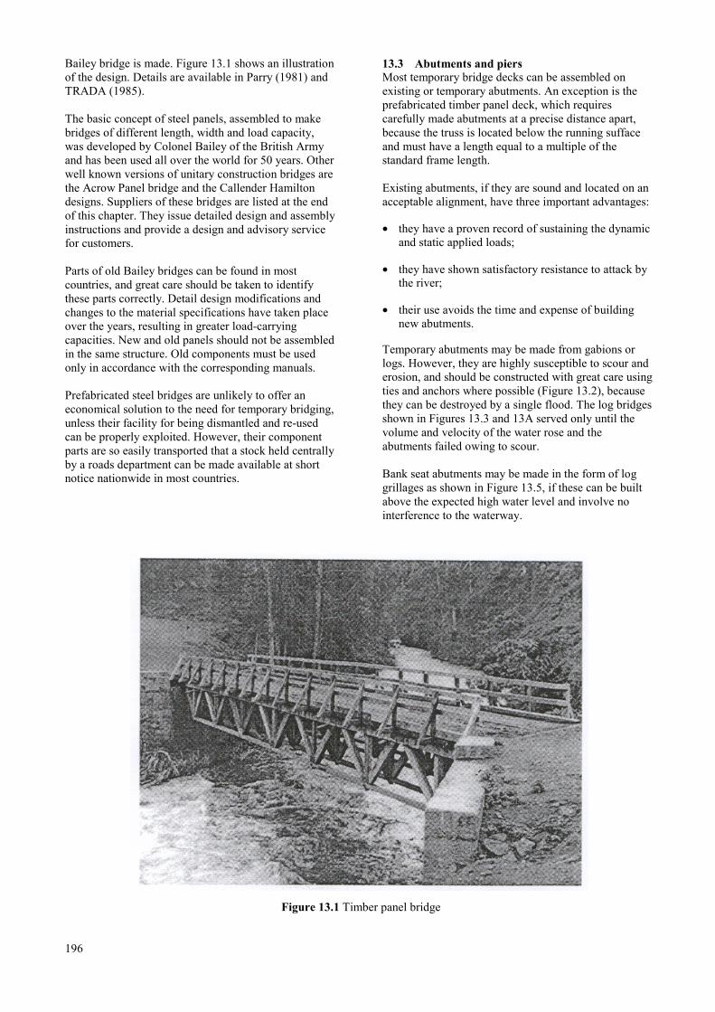
Bailey bridge is made. Figure 13.1 shows an illustrationof the design. Details are available in Parry (1981) andTRADA (1985).
The basic concept of steel panels, assembled to makebridges of different length, width and load capacity,was developed by Colonel Bailey of the British Armyand has been used all over the world for 50 years. Otherwell known versions of unitary construction bridges arethe Acrow Panel bridge and the Callender Hamiltondesigns. Suppliers of these bridges are listed at the endof this chapter. They issue detailed design and assemblyinstructions and provide a design and advisory servicefor customers.
Parts of old Bailey bridges can be found in mostcountries, and great care should be taken to identifythese parts correctly. Detail design modifications andchanges to the material specifications have taken placeover the years, resulting in greater load-carryingcapacities. New and old panels should not be assembledin the same structure. Old components must be usedonly in accordance with the corresponding manuals.
Prefabricated steel bridges are unlikely to offer aneconomical solution to the need for temporary bridging,unless their facility for being dismantled and re-usedcan be properly exploited. However, their componentparts are so easily transported that a stock held centrallyby a roads department can be made available at shortnotice nationwide in most countries.
13.3 Abutments and piersMost temporary bridge decks can be assembled onexisting or temporary abutments. An exception is theprefabricated timber panel deck, which requirescarefully made abutments at a precise distance apart,because the truss is located below the running suffaceand must have a length equal to a multiple of thestandard frame length.
Existing abutments, if they are sound and located on anacceptable alignment, have three important advantages:
• they have a proven record of sustaining the dynamicand static applied loads;
• they have shown satisfactory resistance to attack bythe river;
• their use avoids the time and expense of buildingnew abutments.
Temporary abutments may be made from gabions orlogs. However, they are highly susceptible to scour anderosion, and should be constructed with great care usingties and anchors where possible (Figure 13.2), becausethey can be destroyed by a single flood. The log bridgesshown in Figures 13.3 and 13A served only until thevolume and velocity of the water rose and theabutments failed owing to scour.
Bank seat abutments may be made in the form of loggrillages as shown in Figure 13.5, if these can be builtabove the expected high water level and involve nointerference to the waterway.
Figure 13.1 Timber panel bridge
196
Figure 13.2 Timber abutment tied back to a buried log
Figure 13.3 Temporary bridge on gabion abutments
197
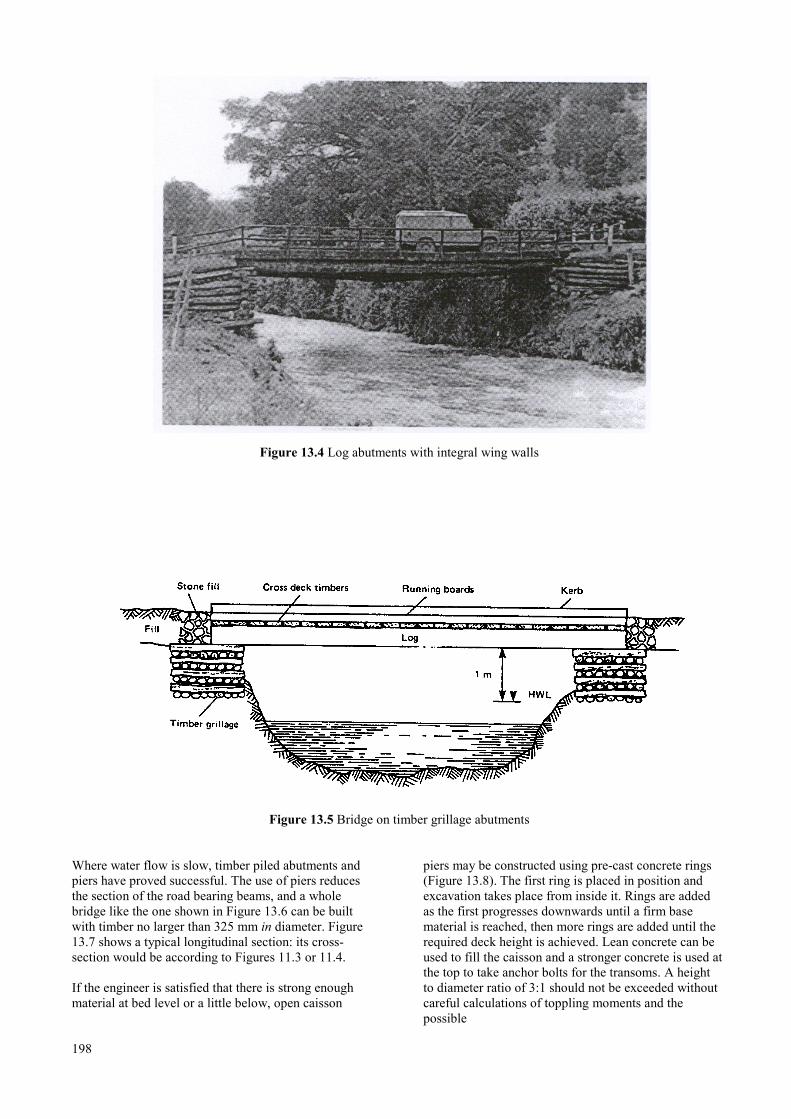
Figure 13.4 Log abutments with integral wing walls
Figure 13.5 Bridge on timber grillage abutments
Where water flow is slow, timber piled abutments andpiers have proved successful. The use of piers reducesthe section of the road bearing beams, and a wholebridge like the one shown in Figure 13.6 can be builtwith timber no larger than 325 mm in diameter. Figure13.7 shows a typical longitudinal section: its cross-section would be according to Figures 11.3 or 11.4.
If the engineer is satisfied that there is strong enoughmaterial at bed level or a little below, open caisson
198
piers may be constructed using pre-cast concrete rings(Figure 13.8). The first ring is placed in position andexcavation takes place from inside it. Rings are addedas the first progresses downwards until a firm basematerial is reached, then more rings are added until therequired deck height is achieved. Lean concrete can beused to fill the caisson and a stronger concrete is used atthe top to take anchor bolts for the transoms. A heightto diameter ratio of 3:1 should not be exceeded withoutcareful calculations of toppling moments and thepossible
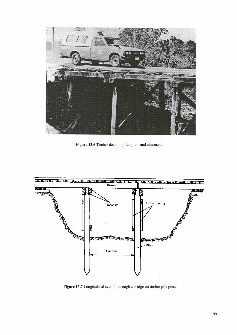
Figure 13.6 Timber deck on piled piers and abutments
Figure 13.7 Longitudinal section through a bridge on timber pile piers
199
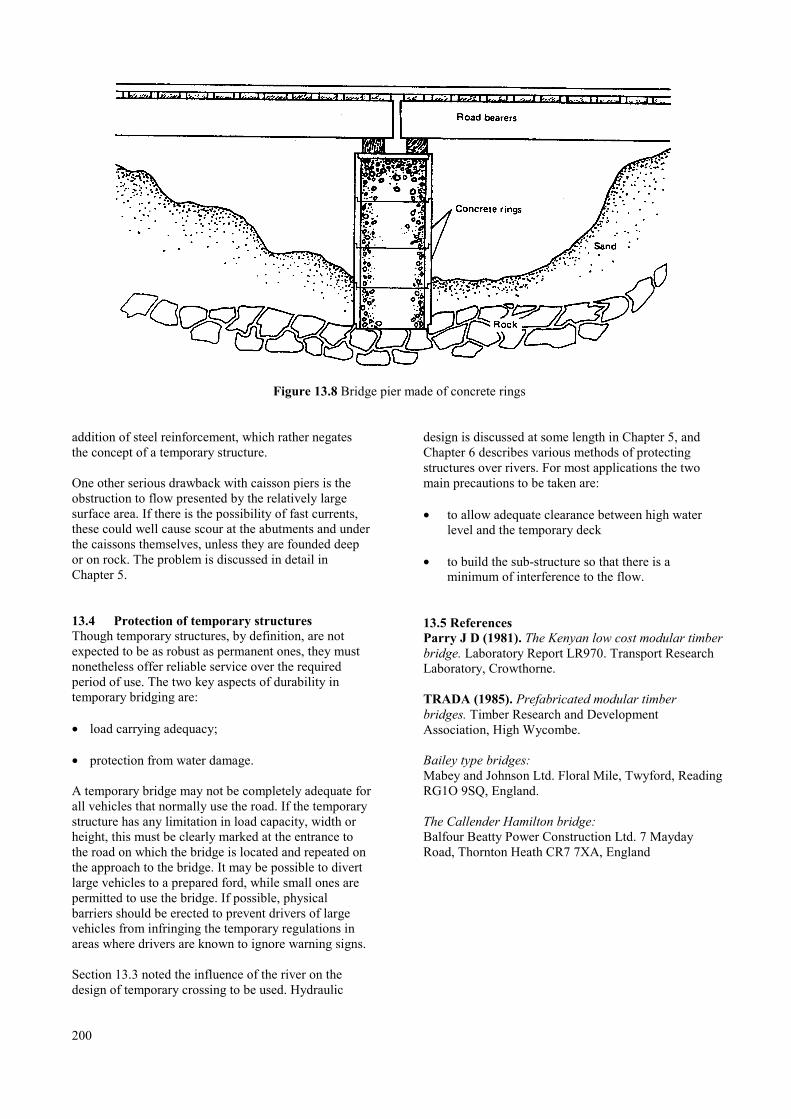
Figure 13.8 Bridge pier made of concrete rings
addition of steel reinforcement, which rather negatesthe concept of a temporary structure.
One other serious drawback with caisson piers is theobstruction to flow presented by the relatively largesurface area. If there is the possibility of fast currents,these could well cause scour at the abutments and underthe caissons themselves, unless they are founded deepor on rock. The problem is discussed in detail inChapter 5.
13.4 Protection of temporary structuresThough temporary structures, by definition, are notexpected to be as robust as permanent ones, they mustnonetheless offer reliable service over the requiredperiod of use. The two key aspects of durability intemporary bridging are:
• load carrying adequacy;
• protection from water damage.
A temporary bridge may not be completely adequate forall vehicles that normally use the road. If the temporarystructure has any limitation in load capacity, width orheight, this must be clearly marked at the entrance tothe road on which the bridge is located and repeated onthe approach to the bridge. It may be possible to divertlarge vehicles to a prepared ford, while small ones arepermitted to use the bridge. If possible, physicalbarriers should be erected to prevent drivers of largevehicles from infringing the temporary regulations inareas where drivers are known to ignore warning signs.
Section 13.3 noted the influence of the river on thedesign of temporary crossing to be used. Hydraulic
200
design is discussed at some length in Chapter 5, andChapter 6 describes various methods of protectingstructures over rivers. For most applications the twomain precautions to be taken are:
• to allow adequate clearance between high waterlevel and the temporary deck
• to build the sub-structure so that there is aminimum of interference to the flow.
13.5 ReferencesParry J D (1981). The Kenyan low cost modular timberbridge. Laboratory Report LR970. Transport ResearchLaboratory, Crowthorne.
TRADA (1985). Prefabricated modular timberbridges. Timber Research and DevelopmentAssociation, High Wycombe.
Bailey type bridges:Mabey and Johnson Ltd. Floral Mile, Twyford, ReadingRG1O 9SQ, England.
The Callender Hamilton bridge:Balfour Beatty Power Construction Ltd. 7 MaydayRoad, Thornton Heath CR7 7XA, England
14 BRIDGE BUILDING MATERIALS
14.1 Concrete ………………………………………………………………………………………………… 203
14.2 Steel reinforcement ……………………………………………………………………………………... 204
14.3 Structural steel beams and steel fittings ………………………………………………………………… 204
14.4 Structural timber ………………………………………………………………………………………... 204
14.4.1 Preservative treatments ……………………………………………………………………… 204
14.4.2 Classification of timber for bridge engineering ……………………………………………... 206
14.5 Masonry ………………………………………………………………………………………………… 206
14.6 Rubber bearings ………………………………………………………………………………………… 206
14.7 Joint sealant …………………………………………………………………………………………….. 208
14.8 Construction joint seals …………………………………………………………………………………. 208
14.9 References ……………………………………………………………………………………………… 208
14.10 Standard drawings for unsealed expansion joints ………………………………………………………. 210
201

202
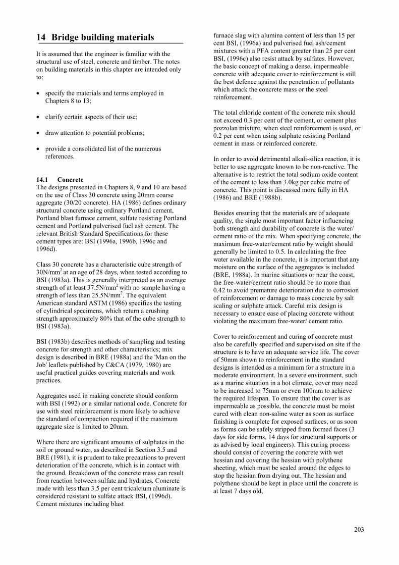
14 Bridge building materials
It is assumed that the engineer is familiar with thestructural use of steel, concrete and timber. The noteson building materials in this chapter are intended onlyto:
• specify the materials and terms employed inChapters 8 to 13;
• clarify certain aspects of their use;
• draw attention to potential problems;
• provide a consolidated list of the numerousreferences.
14.1 ConcreteThe designs presented in Chapters 8, 9 and 10 are basedon the use of Class 30 concrete using 20mm coarseaggregate (30/20 concrete). HA (1986) defines ordinarystructural concrete using ordinary Portland cement,Portland blast furnace cement, sulfate resisting Portlandcement and Portland pulverised fuel ash cement. Therelevant British Standard Specifications for thesecement types are: BSI (1996a, 1996b, 1996c and1996d).
Class 30 concrete has a characteristic cube strength of30N/mm2 at an age of 28 days, when tested according toBSI (1983a). This is generally interpreted as an averagestrength of at least 37.5N/mm2 with no sample having astrength of less than 25.5N/mm2. The equivalentAmerican standard ASTM (1986) specifies the testingof cylindrical specimens, which return a crushingstrength approximately 80% that of the cube strength toBSI (1983a).
BSI (1983b) describes methods of sampling and testingconcrete for strength and other characteristics; mixdesign is described in BRE (1988a) and the 'Man on theJob' leaflets published by C&CA (1979, 1980) areuseful practical guides covering materials and workpractices.
Aggregates used in making concrete should conformwith BSI (1992) or a similar national code. Concrete foruse with steel reinforcement is more likely to achievethe standard of compaction required if the maximumaggregate size is limited to 20mm.
Where there are significant amounts of sulphates in thesoil or ground water, as described in Section 3.5 andBRE (1981), it is prudent to take precautions to preventdeterioration of the concrete, which is in contact withthe ground. Breakdown of the concrete mass can resultfrom reaction between sulfate and hydrates. Concretemade with less than 3.5 per cent tricalcium aluminate isconsidered resistant to sulfate attack BSI, (1996d).Cement mixtures including blast
furnace slag with alumina content of less than 15 percent BSI, (1996a) and pulverised fuel ash/cementmixtures with a PFA content greater than 25 per centBSI, (1996c) also resist attack by sulfates. However,the basic concept of making a dense, impermeableconcrete with adequate cover to reinforcement is stillthe best defence against the penetration of pollutantswhich attack the concrete mass or the steelreinforcement.
The total chloride content of the concrete mix shouldnot exceed 0.3 per cent of the cement, or cement pluspozzolan mixture, when steel reinforcement is used, or0.2 per cent when using sulphate resisting Portlandcement in mass or reinforced concrete.
In order to avoid detrimental alkali-silica reaction, it isbetter to use aggregate known to be non-reactive. Thealternative is to restrict the total sodium oxide contentof the cement to less than 3.0kg per cubic metre ofconcrete. This point is discussed more fully in HA(1986) and BRE (1988b).
Besides ensuring that the materials are of adequatequality, the single most important factor influencingboth strength and durability of concrete is the water/cement ratio of the mix. When specifying concrete, themaximum free-water/cement ratio by weight shouldgenerally be limited to 0.5. In calculating the freewater available in the concrete, it is important that anymoisture on the surface of the aggregates is included(BRE, 1988a). In marine situations or near the coast,the free-water/cement ratio should be no more than0.42 to avoid premature deterioration due to corrosionof reinforcement or damage to mass concrete by saltscaling or sulphate attack. Careful mix design isnecessary to ensure ease of placing concrete withoutviolating the maximum free-water/ cement ratio.
Cover to reinforcement and curing of concrete mustalso be carefully specified and supervised on site if thestructure is to have an adequate service life. The coverof 50mm shown to reinforcement in the standarddesigns is intended as a minimum for a structure in amoderate environment. In a severe environment, suchas a marine situation in a hot climate, cover may needto be increased to 75mm or even 100mm to achievethe required lifespan. To ensure that the cover is asimpermeable as possible, the concrete must be moistcured with clean non-saline water as soon as surfacefinishing is complete for exposed surfaces, or as soonas forms can be safely stripped from formed faces (3days for side forms, 14 days for structural supports oras advised by local engineers). This curing processshould consist of covering the concrete with wethessian and covering the hessian with polythenesheeting, which must be sealed around the edges tostop the hessian from drying out. The hessian andpolythene should be kept in place until the concrete isat least 7 days old,
203
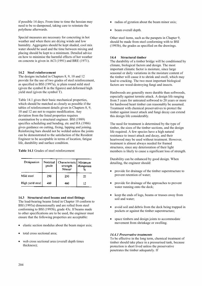
if possible 14 days. From time to time the hessian mayneed to be re-dampened, taking care to reinstate thepolythene afterwards.
Special measures are necessary for concreting in hotweather and when there are drying winds and lowhumidity. Aggregates should be kept shaded, cool mixwater should be used and the time between mixing andplacing should be kept to a minimum. Detailed adviceon how to minimise the harmful effects of hot weatheron concrete is given in ACI (1991) and BRE (1971).
14.2 Steel reinforcementThe designs included in Chapters 8, 9, 10 and 12provide for the use of two grades of steel reinforcement,as specified in BSI (1997a), ie plain round mild steel(given the symbol R in the figures) and deformed highyield steel (given the symbol T).
Table 14.1 gives their basic mechanical properties,which should be matched as closely as possible if thetables of reinforcement details given in Chapters 8, 9,10 and 12 are not to require modification. Anydeviation from the listed properties requiresexamination by a structural engineer. BSI (1989)specifies scheduling and bending, etc and HA (1986)gives guidance on cutting, fixing, lapping and joining.Reinforcing bars should not be welded unless the jointscan be demonstrated to the satisfaction of the ResidentEngineer to be acceptable in terms of location, fatiguelife, durability and surface condition.
Table 14.1 Grades of steel reinforcement
14.3 Structural steel beams and steel fittingsThe load-bearing beams listed in Chapter 10 conform toBSI (1993a) dimensionally and are rolled from steelconforming to BSI (1993b), grade 43c. If beams madeto other specifications are to be used, the engineer mustensure that the following properties are acceptable:
• elastic section modulus about the beam major axis;
• total cross sectional area;
• web cross sectional area (overall depth timesthickness);
204
• radius of gyration about the beam minor axis;
• beam overall depth.
Other steel items, such as the parapets in Chapter 9,should be made from steel conforming with to BSI(1993b), the grades as specified on the drawings.
14.4 Structural timberThe durability of a timber bridge will be conditioned byclimate, biological factors and design. The mostimportant climatic factor is moisture, since largeseasonal or daily variations in the moisture content ofthe timber will cause it to shrink and swell, which maylead to cracking. The two most important biologicalfactors are wood-destroying fungi and insects.
Hardwoods are generally more durable than softwoods,especially against termite attack. A design life rangingfrom 5 years for untreated softwood to 20 years or morefor hardwood heart timber can reasonably be assumed.Treatment with chemical preservatives to protect thetimber against insect attack and fungi decay can extendthis design life considerably.
The need for treatment is determined by the type oftimber, the sizes of the timber sections, and the designlife required. A few species have a high naturalresistance to insect attack and decay, and theirheartwood may be used without treatment. However,treatment is almost always needed for framedstructures, since any deterioration of their lightmembers is likely to cause a significant loss of strength.
Durability can be enhanced by good design. Whendetailing, the engineer should:
• provide for drainage of the timber superstructure toprevent retention of water;
• provide for drainage of the approaches to preventwater running onto the deck;
• keep the ends of logs, beams or trusses away fromsoil and water;
• avoid soil and debris from the deck being trapped inpockets or against the timber superstructure;
• space timbers and design joints to accommodatemovement from shrinkage or swelling.
14.4.1 Preservative treatmentsTo be effective in the long term, chemical treatment oftimber should take place in a pressurised tank, becauseprotection is short lived unless the preservativepenetrates the timber adequately. If
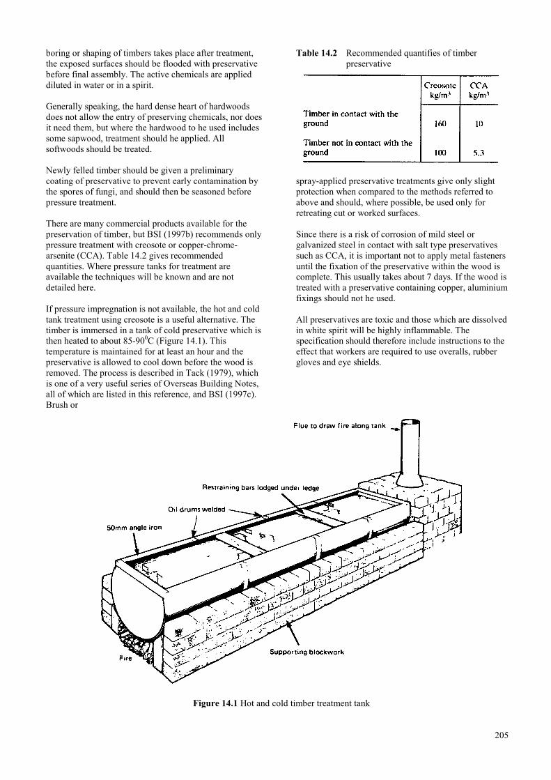
boring or shaping of timbers takes place after treatment,the exposed surfaces should be flooded with preservativebefore final assembly. The active chemicals are applieddiluted in water or in a spirit.
Generally speaking, the hard dense heart of hardwoodsdoes not allow the entry of preserving chemicals, nor doesit need them, but where the hardwood to he used includessome sapwood, treatment should he applied. Allsoftwoods should be treated.
Newly felled timber should be given a preliminarycoating of preservative to prevent early contamination bythe spores of fungi, and should then be seasoned beforepressure treatment.
There are many commercial products available for thepreservation of timber, but BSI (1997b) recommends onlypressure treatment with creosote or copper-chrome-arsenite (CCA). Table 14.2 gives recommendedquantities. Where pressure tanks for treatment areavailable the techniques will be known and are notdetailed here.
If pressure impregnation is not available, the hot and coldtank treatment using creosote is a useful alternative. Thetimber is immersed in a tank of cold preservative which isthen heated to about 85-900C (Figure 14.1). Thistemperature is maintained for at least an hour and thepreservative is allowed to cool down before the wood isremoved. The process is described in Tack (1979), whichis one of a very useful series of Overseas Building Notes,all of which are listed in this reference, and BSI (1997c).Brush or
Table 14.2 Recommended quantifies of timberpreservative
spray-applied preservative treatments give only slightprotection when compared to the methods referred toabove and should, where possible, be used only forretreating cut or worked surfaces.
Since there is a risk of corrosion of mild steel orgalvanized steel in contact with salt type preservativessuch as CCA, it is important not to apply metal fastenersuntil the fixation of the preservative within the wood iscomplete. This usually takes about 7 days. If the wood istreated with a preservative containing copper, aluminiumfixings should not he used.
All preservatives are toxic and those which are dissolvedin white spirit will be highly inflammable. Thespecification should therefore include instructions to theeffect that workers are required to use overalls, rubbergloves and eye shields.
Figure 14.1 Hot and cold timber treatment tank
205
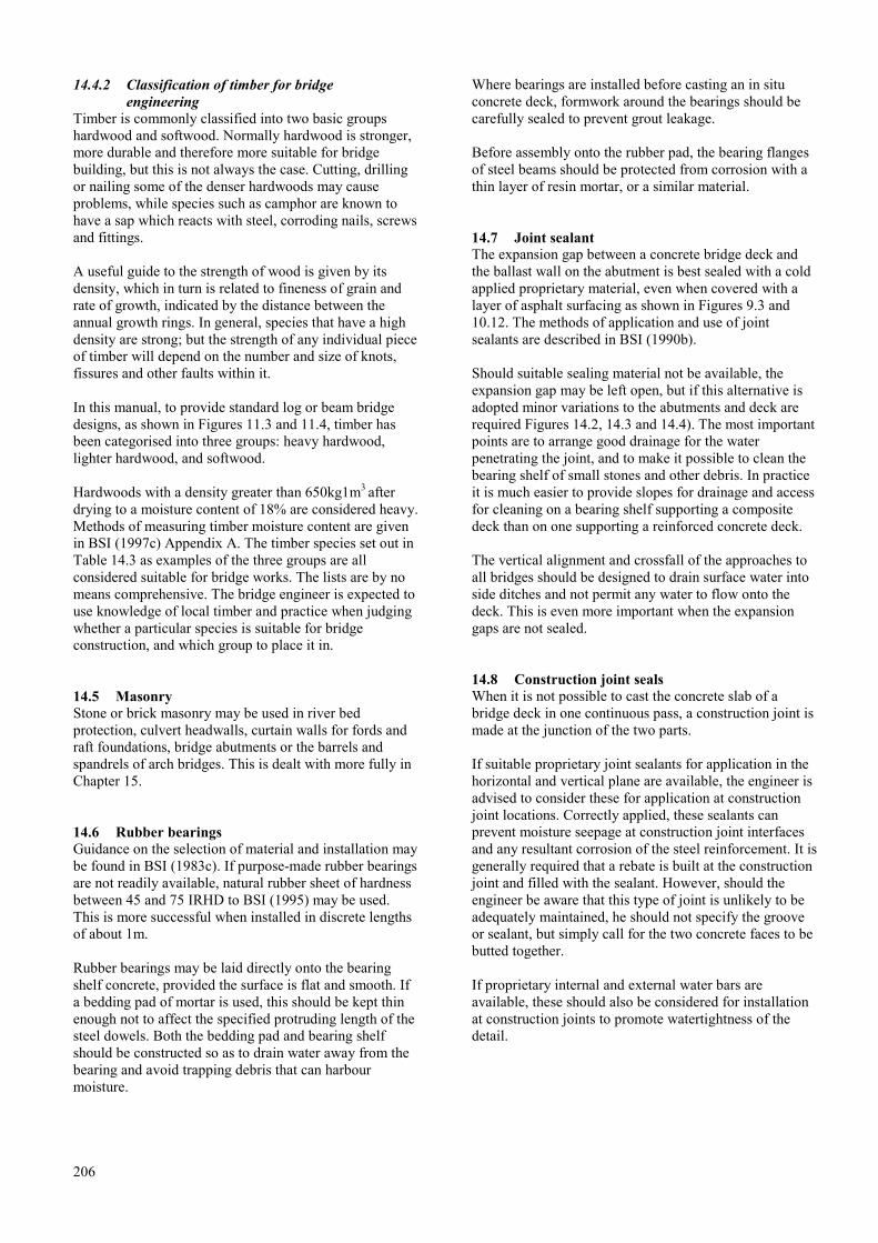
14.4.2 Classification of timber for bridgeengineering
Timber is commonly classified into two basic groupshardwood and softwood. Normally hardwood is stronger,more durable and therefore more suitable for bridgebuilding, but this is not always the case. Cutting, drillingor nailing some of the denser hardwoods may causeproblems, while species such as camphor are known tohave a sap which reacts with steel, corroding nails, screwsand fittings.
A useful guide to the strength of wood is given by itsdensity, which in turn is related to fineness of grain andrate of growth, indicated by the distance between theannual growth rings. In general, species that have a highdensity are strong; but the strength of any individual pieceof timber will depend on the number and size of knots,fissures and other faults within it.
In this manual, to provide standard log or beam bridgedesigns, as shown in Figures 11.3 and 11.4, timber hasbeen categorised into three groups: heavy hardwood,lighter hardwood, and softwood.
Hardwoods with a density greater than 650kg1m3 afterdrying to a moisture content of 18% are considered heavy.Methods of measuring timber moisture content are givenin BSI (1997c) Appendix A. The timber species set out inTable 14.3 as examples of the three groups are allconsidered suitable for bridge works. The lists are by nomeans comprehensive. The bridge engineer is expected touse knowledge of local timber and practice when judgingwhether a particular species is suitable for bridgeconstruction, and which group to place it in.
14.5 MasonryStone or brick masonry may be used in river bedprotection, culvert headwalls, curtain walls for fords andraft foundations, bridge abutments or the barrels andspandrels of arch bridges. This is dealt with more fully inChapter 15.
14.6 Rubber bearingsGuidance on the selection of material and installation maybe found in BSI (1983c). If purpose-made rubber bearingsare not readily available, natural rubber sheet of hardnessbetween 45 and 75 IRHD to BSI (1995) may be used.This is more successful when installed in discrete lengthsof about 1m.
Rubber bearings may be laid directly onto the bearingshelf concrete, provided the surface is flat and smooth. Ifa bedding pad of mortar is used, this should be kept thinenough not to affect the specified protruding length of thesteel dowels. Both the bedding pad and bearing shelfshould be constructed so as to drain water away from thebearing and avoid trapping debris that can harbourmoisture.
206
Where bearings are installed before casting an in situconcrete deck, formwork around the bearings should becarefully sealed to prevent grout leakage.
Before assembly onto the rubber pad, the bearing flangesof steel beams should be protected from corrosion with athin layer of resin mortar, or a similar material.
14.7 Joint sealantThe expansion gap between a concrete bridge deck andthe ballast wall on the abutment is best sealed with a coldapplied proprietary material, even when covered with alayer of asphalt surfacing as shown in Figures 9.3 and10.12. The methods of application and use of jointsealants are described in BSI (1990b).
Should suitable sealing material not be available, theexpansion gap may be left open, but if this alternative isadopted minor variations to the abutments and deck arerequired Figures 14.2, 14.3 and 14.4). The most importantpoints are to arrange good drainage for the waterpenetrating the joint, and to make it possible to clean thebearing shelf of small stones and other debris. In practiceit is much easier to provide slopes for drainage and accessfor cleaning on a bearing shelf supporting a compositedeck than on one supporting a reinforced concrete deck.
The vertical alignment and crossfall of the approaches toall bridges should be designed to drain surface water intoside ditches and not permit any water to flow onto thedeck. This is even more important when the expansiongaps are not sealed.
14.8 Construction joint sealsWhen it is not possible to cast the concrete slab of abridge deck in one continuous pass, a construction joint ismade at the junction of the two parts.
If suitable proprietary joint sealants for application in thehorizontal and vertical plane are available, the engineer isadvised to consider these for application at constructionjoint locations. Correctly applied, these sealants canprevent moisture seepage at construction joint interfacesand any resultant corrosion of the steel reinforcement. It isgenerally required that a rebate is built at the constructionjoint and filled with the sealant. However, should theengineer be aware that this type of joint is unlikely to beadequately maintained, he should not specify the grooveor sealant, but simply call for the two concrete faces to bebutted together.
If proprietary internal and external water bars areavailable, these should also be considered for installationat construction joints to promote watertightness of thedetail.

Table 14.3 Timber species suitable for bridge beams
207

Table 14.4 Permissible short-term stresses
14.9 ReferencesACI (1991) Hot weather concreting. Manual ofconcrete practice A CI3OSR-89. American ConcreteInstitute, Detroit.
ASTM (1986). Standard test methods for compressivestrength of cylindrical concrete specimens. C39.American Society for Testing of Materials, Philadelphia.
BRE (1971). Problems of concrete production in aridclimates. Overseas Building Notes No.139. BuildingResearch Establishment, Watford.
BRE (1975). The hot and cold open tank process ofimpregnating timber. Technical Note No 42. BuildingResearch Establishment, Watford.
BRE (1981). Concrete in sulphate-bearing soils andground waters. BRE Digest 250. Building ResearchEstablishment, Watford.
BRE (1988a). Design of normal concrete mixes.Building Research Establishment, Watford.
BRE (1988b). Alkali aggregate reactions in concrete.BRE Digest 330. Building Research Establishment,Watford.
BSI (1983a). Methods of testing concrete Part 116.Method for determination of compressive strength ofconcrete cubes. BS 1881: 1983 Pt 116. BritishStandards Institution, London.
BSI (1983b). Methods of testing concrete Parts 101 to127. BS 1881.1983. British Standards Institution,London.
208
BSI (1983c). Steel concrete and composite bridges,Section 9.2. Specification for materials, manufacture andinstallation of bridge bearings. BS 5400 Section9.2:1983. British Standards Institution, London.
BSI (1989). Scheduling, dimensioning, bending andcutting of steel reinforcement for concrete. BS 4466:1989. British Standards Institution, London.
BSI (1990b). Cold applied joint sealant systems forconcrete pavements Part 2. Code of practice for theapplication and use of joint sealants. BS 5212 Pt 2:1990.British Standards Institution, London.
BSI (1992). Aggregates from natural sources forconcrete. BS 882:1992. British Standards Institution,London.
BSI (1993a). Structural steel sections Part 1. Specification for hot-rolled sections. BS 4:1993 Pt 1. British Standards Institution, London.
BSI (1993b) Weldable structural steels. BS EN 10025:1993. British Standards Institution, London
BSI (1995). Methods of testing vulcanised rubber Part A26. Determination of hardness. BS 903: 1995 Pt A 26.British Standards Institution, London.
BSI (1996a). Portland blast furnace cement Part 2.Metric units. 135146: 1996 Pt2. British StandardsInstitution, London.
BSI (1996b). Portland cements. BS 12:1996. BritishStandards Institution, London.
BSI (1996c). Portland pulverised fuel ash cement. BS658& 1996. British Standards Institution, London.
BSI (1996d). Sulphate resisting Portland cement. 1354027.1996. British Standards Institution, London.
BSI (1997a). Carbon steel bars for the reinforcement ofconcrete. 1354449:1997. British Standards Institution,London.
BSI (1997b). Structural use of timber Part 5. Code ofpractice for the preservative treatment of structuraltimber. 135 526&~1 997. Pt 5. British StandardsInstitution, London.
BSI (1997c). Wood preservation using coal tar creosotesPart 2. Methods for timber treatment. 135 144: 1997.British Standards Institution, London.
C&CA (1979, 1980). Man on the job leaflets. Nos45.101 to 45.116. Cement and Concrete Association,Slough.
Highways Agency (1986). Specification for HighwayWorks. Part 5, series 1700 Structural concrete. StationeryOffice, London.
Tack C H (1979). Preservation of timber for tropicalbuilding. Overseas building notes, No 183. BuildingResearch Establishment, Watford.

14.10 Standard drawings for unsealed expansion joints
Title Figure number
Alternative expansion joint on a concrete deck …………………………………………………………………… 14.2
Alternative expansion joint on a composite deck …………………………………………………………………. 14.3
Alternative expansion joint at a pier ………………………………………………………………………………. 14.4
209
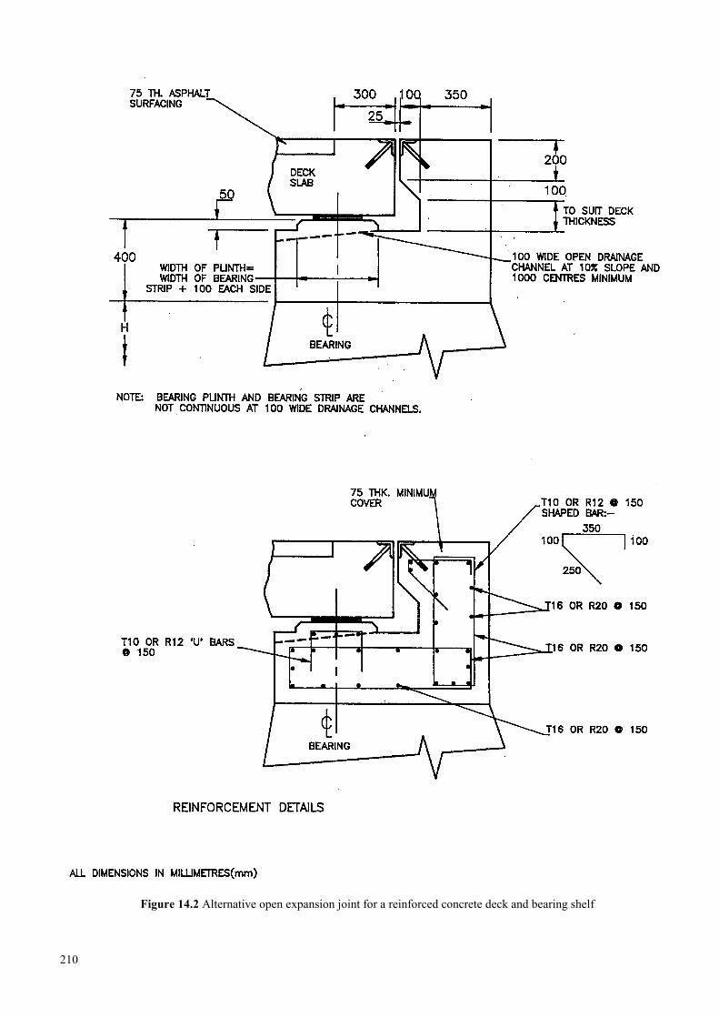
Figure 14.2 Alternative open expansion joint for a reinforced concrete deck and bearing shelf
210
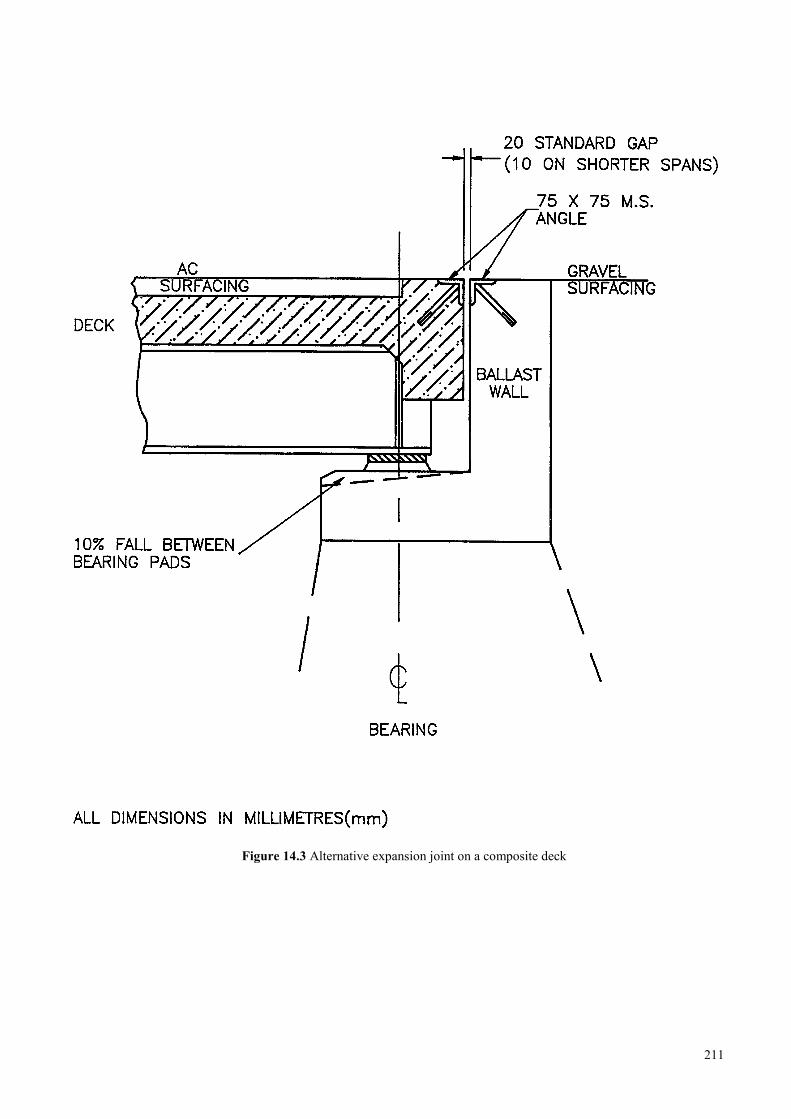
Figure 14.3 Alternative expansion joint on a composite deck
211
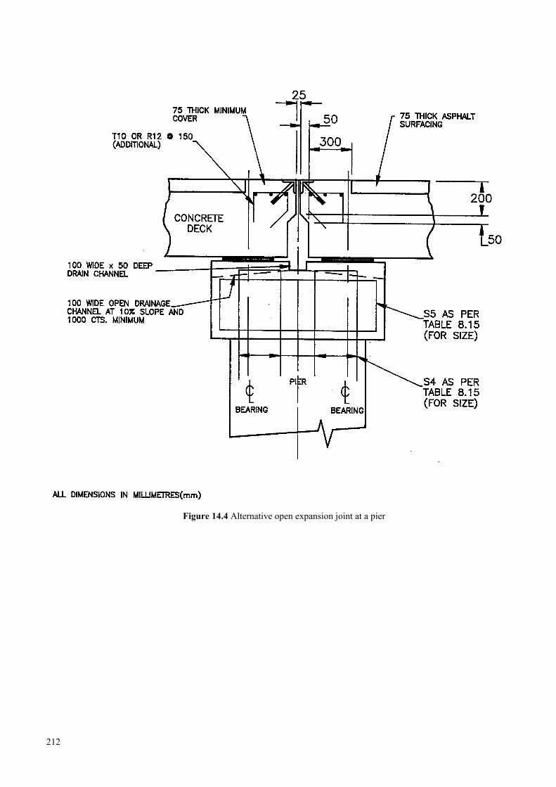
Figure 14.4 Alternative open expansion joint at a pier
212
15 MASONRY
15.1 Use of stone and brick masonry for road works ………………………………………………………... 217
15.2 Design guidelines ……………………………………………………………………………………….. 217
15.2.1 Foundations ………………………………………………………………………………….. 217
15.2.2 Walls ………………………………………………………………………………………… 218
15.2.3 Retaining walls ……………………………………………………………………………… 218
15.3 Materials and quantities ………………………………………………………………………………… 218
15.3.1 Mortar ………………………………………………………………………………….……. 218
15.3.2 Cement ………………………………………………………………………………………. 219
15.3.3 Sand ………………………………………………………………………………………….. 219
15.3.4 Water ………………………………………………………………………………………… 219
15.3.5 Stones ………………………………………………………………………………………... 219
15.3.6 Bricks ………………………………………………………………………………………... 219
15.4 Masonry work …………………………………………………………………………………………... 219
15.4.1 Joints and Pointing …………………………………………………………………………... 219
15.4.2 Bond for stone masonry ……………………………………………………………………... 220
15.4.3 Mortar mixing ……………………………………………………………………………….. 220
15.4.4 Rules for good quality mortar-stone masonry construction: ………………………………… 221
15.5 Arches ………………………………………………………………………………………………….. 221
15.5.1 Arched culverts ……………………………………………………………………………… 221
15.6 Dry stone masonry ……………………………………………………………………………………… 222
15.7 Masonry for river bed or slope protection ……………………………………………………………… 222
15.8 References ………………………………………………………………………………………………. 223
213

214
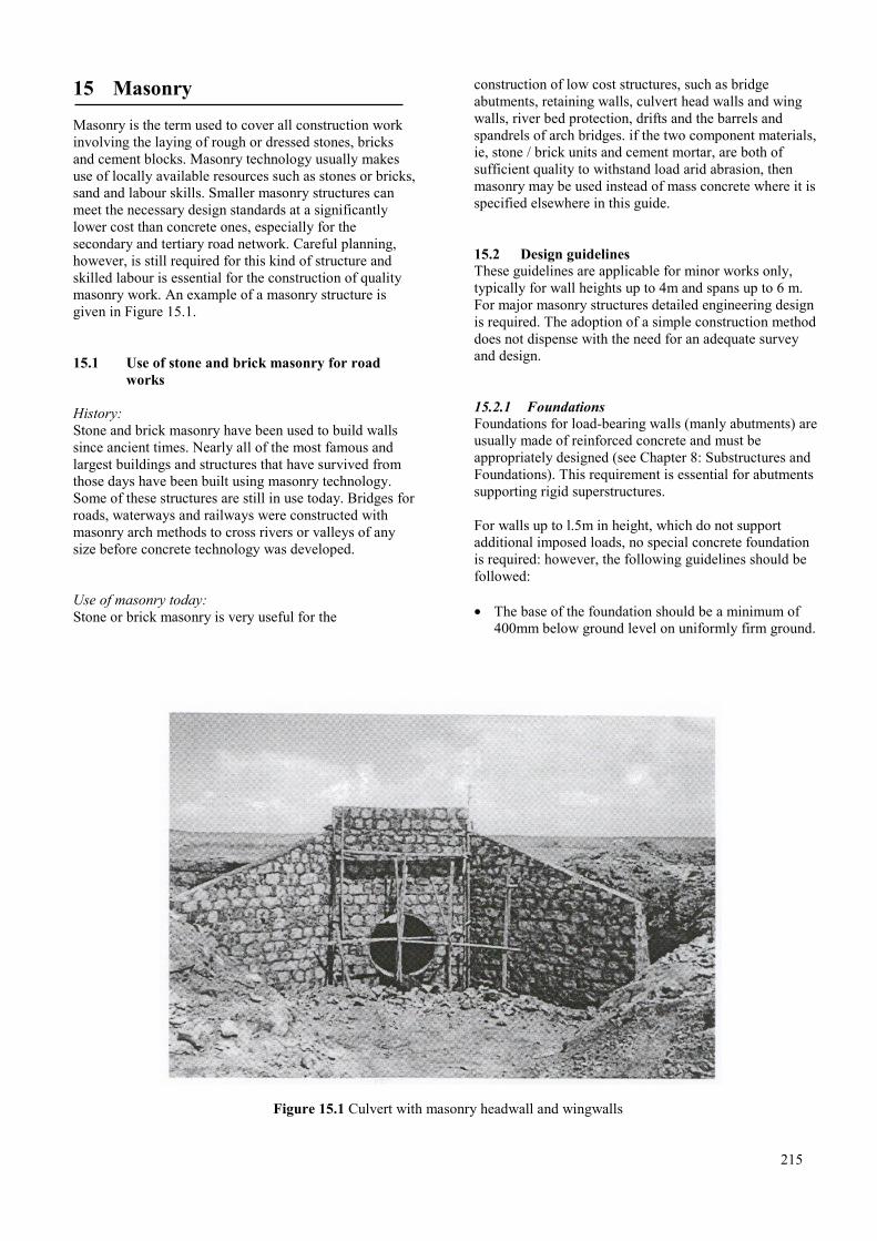
15 Masonry
Masonry is the term used to cover all construction workinvolving the laying of rough or dressed stones, bricksand cement blocks. Masonry technology usually makesuse of locally available resources such as stones or bricks,sand and labour skills. Smaller masonry structures canmeet the necessary design standards at a significantlylower cost than concrete ones, especially for thesecondary and tertiary road network. Careful planning,however, is still required for this kind of structure andskilled labour is essential for the construction of qualitymasonry work. An example of a masonry structure isgiven in Figure 15.1.
15.1 Use of stone and brick masonry for roadworks
History:Stone and brick masonry have been used to build wallssince ancient times. Nearly all of the most famous andlargest buildings and structures that have survived fromthose days have been built using masonry technology.Some of these structures are still in use today. Bridges forroads, waterways and railways were constructed withmasonry arch methods to cross rivers or valleys of anysize before concrete technology was developed.
Use of masonry today:Stone or brick masonry is very useful for the
construction of low cost structures, such as bridgeabutments, retaining walls, culvert head walls and wingwalls, river bed protection, drifts and the barrels andspandrels of arch bridges. if the two component materials,ie, stone / brick units and cement mortar, are both ofsufficient quality to withstand load arid abrasion, thenmasonry may be used instead of mass concrete where it isspecified elsewhere in this guide.
15.2 Design guidelinesThese guidelines are applicable for minor works only,typically for wall heights up to 4m and spans up to 6 m.For major masonry structures detailed engineering designis required. The adoption of a simple construction methoddoes not dispense with the need for an adequate surveyand design.
15.2.1 FoundationsFoundations for load-bearing walls (manly abutments) areusually made of reinforced concrete and must beappropriately designed (see Chapter 8: Substructures andFoundations). This requirement is essential for abutmentssupporting rigid superstructures.
For walls up to l.5m in height, which do not supportadditional imposed loads, no special concrete foundationis required: however, the following guidelines should befollowed:
• The base of the foundation should be a minimum of400mm below ground level on uniformly firm ground.
Figure 15.1 Culvert with masonry headwall and wingwalls
215
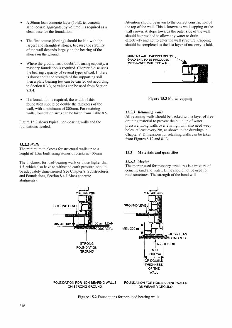
• A 50mm lean concrete layer (1:4:8, ie, cement:sand: coarse aggregate, by volume), is required as aclean base for the foundation.
• The first course (footing) should be laid with thelargest and straightest stones, because the stabilityof the wall depends largely on the bearing of thestones on the ground.
• Where the ground has a doubtful bearing capacity, amasonry foundation is required. Chapter 8 discussesthe bearing capacity of several types of soil. If thereis doubt about the strength of the supporting soilthen a plate bearing test can be carried out accordingto Section 8.3.3, or values can be used from Section8.3.4.
• If a foundation is required, the width of thisfoundation should be double the thickness of thewall, with a minimum of 800mm. For retainingwalls, foundation sizes can be taken from Table 8.5.
Figure 15.2 shows typical non-bearing walls and thefoundations needed.
15.2.2 WallsThe minimum thickness for structural walls up to aheight of 1.5m built using stones of bricks is 400mm
The thickness for load-bearing walls or those higher than1.5, which also have to withstand earth pressure, shouldbe adequately dimensioned (see Chapter 8: Substructuresand Foundations, Section 8.4.1 Mass concreteabutments).
Attention should be given to the correct construction ofthe top of the wall. This is known as wall capping or thewall crown. A slope towards the outer side of the wallshould be provided to allow any water to draineffectively and not to enter the wall structure. Cappingshould be completed as the last layer of masonry is laid.
Figure 15.3 Mortar capping
15.2.3 Retaining wallsAll retaining walls should be backed with a layer of free-draining material to prevent the build up of waterpressure. Long walls over 2m high will also need weepholes, at least every 2m, as shown in the drawings inChapter 8. Dimensions for retaining walls can be takenfrom Figures 8.12 and 8.13.
15.3 Materials and quantities
15.3.1 MortarThe mortar used for masonry structures is a mixture ofcement, sand and water. Lime should not be used forroad structures. The strength of the bond will
Figure 15.2 Foundations for non-load bearing walls
216
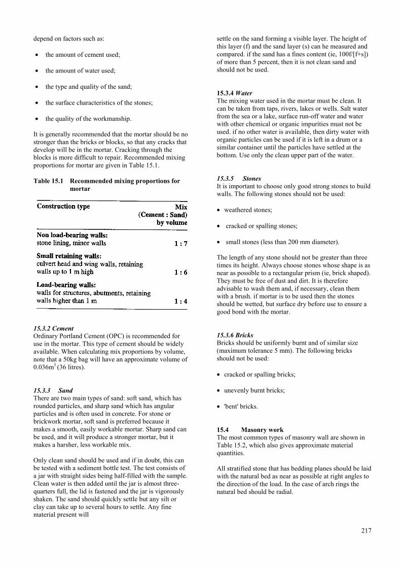
depend on factors such as:
• the amount of cement used;
• the amount of water used;
• the type and quality of the sand;
• the surface characteristics of the stones;
• the quality of the workmanship.
It is generally recommended that the mortar should be nostronger than the bricks or blocks, so that any cracks thatdevelop will be in the mortar. Cracking through theblocks is more difficult to repair. Recommended mixingproportions for mortar are given in Table 15.1.
Table 15.1 Recommended mixing proportions formortar
15.3.2 CementOrdinary Portland Cement (OPC) is recommended foruse in the mortar. This type of cement should be widelyavailable. When calculating mix proportions by volume,note that a 50kg bag will have an approximate volume of0.036m3 (36 litres).
15.3.3 SandThere are two main types of sand: soft sand, which hasrounded particles, and sharp sand which has angularparticles and is often used in concrete. For stone orbrickwork mortar, soft sand is preferred because itmakes a smooth, easily workable mortar. Sharp sand canbe used, and it will produce a stronger mortar, but itmakes a harsher, less workable mix.
Only clean sand should be used and if in doubt, this canbe tested with a sediment bottle test. The test consists ofa jar with straight sides being half-filled with the sample.Clean water is then added until the jar is almost three-quarters full, the lid is fastened and the jar is vigorouslyshaken. The sand should quickly settle but any silt orclay can take up to several hours to settle. Any finematerial present will
settle on the sand forming a visible layer. The height ofthis layer (f) and the sand layer (s) can he measured andcompared. if the sand has a fines content (ie, 100f/[f+s])of more than 5 percent, then it is not clean sand andshould not be used.
15.3.4 WaterThe mixing water used in the mortar must be clean. Itcan be taken from taps, rivers, lakes or wells. Salt waterfrom the sea or a lake, surface run-off water and waterwith other chemical or organic impurities must not beused. if no other water is available, then dirty water withorganic particles can be used if it is left in a drum or asimilar container until the particles have settled at thebottom. Use only the clean upper part of the water.
15.3.5 StonesIt is important to choose only good strong stones to buildwalls. The following stones should not be used:
• weathered stones;
• cracked or spalling stones;
• small stones (less than 200 mm diameter).
The length of any stone should not be greater than threetimes its height. Always choose stones whose shape is asnear as possible to a rectangular prism (ie, brick shaped).They must be free of dust and dirt. It is thereforeadvisable to wash them and, if necessary, clean themwith a brush. if mortar is to be used then the stonesshould be wetted, but surface dry before use to ensure agood bond with the mortar.
15.3.6 BricksBricks should be uniformly burnt and of similar size(maximum tolerance 5 mm). The following bricksshould not be used:
• cracked or spalling bricks;
• unevenly burnt bricks;
• 'bent' bricks.
15.4 Masonry workThe most common types of masonry wall are shown inTable 15.2, which also gives approximate materialquantities.
All stratified stone that has bedding planes should be laidwith the natural bed as near as possible at right angles tothe direction of the load. In the case of arch rings thenatural bed should be radial.
217
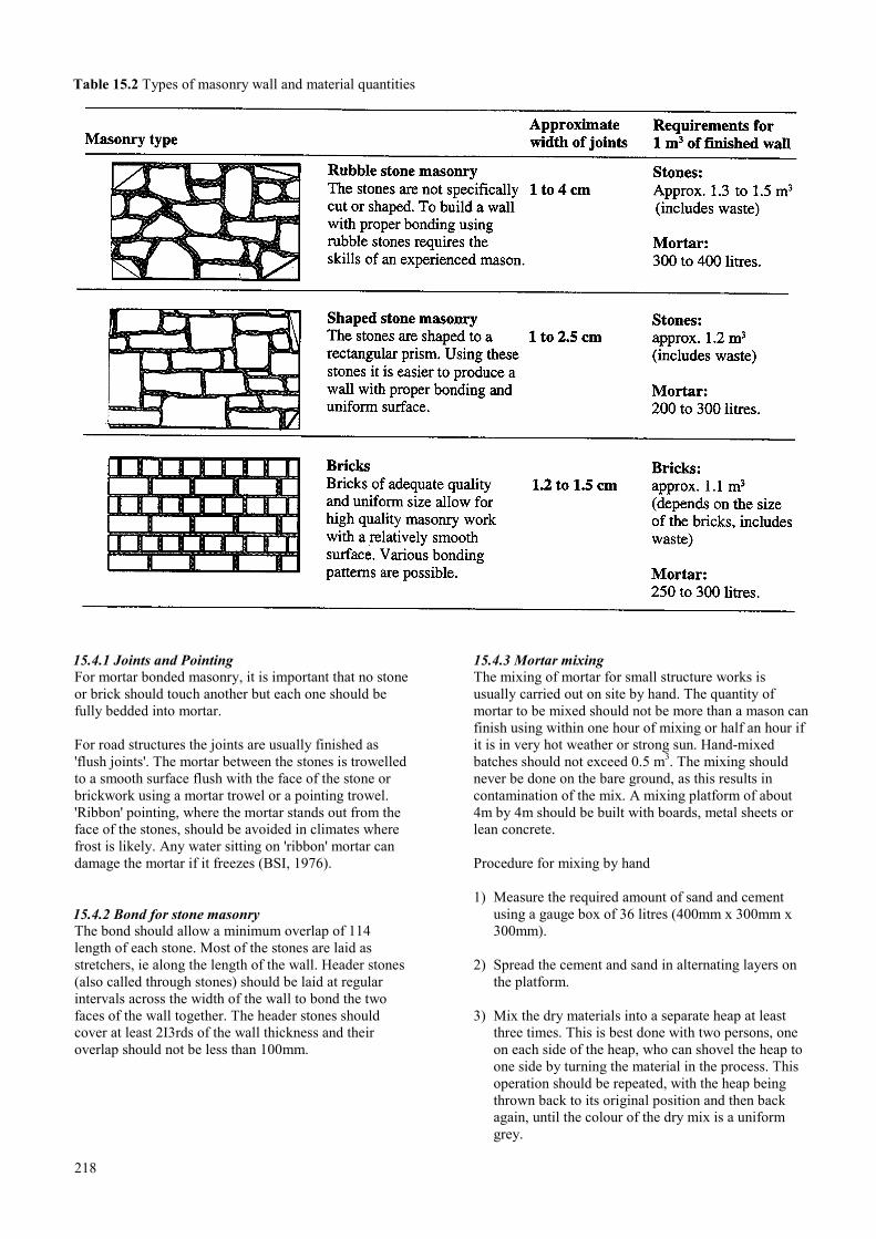
Table 15.2 Types of masonry wall and material quantities
15.4.1 Joints and PointingFor mortar bonded masonry, it is important that no stoneor brick should touch another but each one should befully bedded into mortar.
For road structures the joints are usually finished as'flush joints'. The mortar between the stones is trowelledto a smooth surface flush with the face of the stone orbrickwork using a mortar trowel or a pointing trowel.'Ribbon' pointing, where the mortar stands out from theface of the stones, should be avoided in climates wherefrost is likely. Any water sitting on 'ribbon' mortar candamage the mortar if it freezes (BSI, 1976).
15.4.2 Bond for stone masonryThe bond should allow a minimum overlap of 114length of each stone. Most of the stones are laid asstretchers, ie along the length of the wall. Header stones(also called through stones) should be laid at regularintervals across the width of the wall to bond the twofaces of the wall together. The header stones shouldcover at least 2I3rds of the wall thickness and theiroverlap should not be less than 100mm.
218
15.4.3 Mortar mixingThe mixing of mortar for small structure works isusually carried out on site by hand. The quantity ofmortar to be mixed should not be more than a mason canfinish using within one hour of mixing or half an hour ifit is in very hot weather or strong sun. Hand-mixedbatches should not exceed 0.5 m3. The mixing shouldnever be done on the bare ground, as this results incontamination of the mix. A mixing platform of about4m by 4m should be built with boards, metal sheets orlean concrete.
Procedure for mixing by hand
1) Measure the required amount of sand and cementusing a gauge box of 36 litres (400mm x 300mm x300mm).
2) Spread the cement and sand in alternating layers onthe platform.
3) Mix the dry materials into a separate heap at leastthree times. This is best done with two persons, oneon each side of the heap, who can shovel the heap toone side by turning the material in the process. Thisoperation should be repeated, with the heap beingthrown back to its original position and then backagain, until the colour of the dry mix is a uniformgrey.
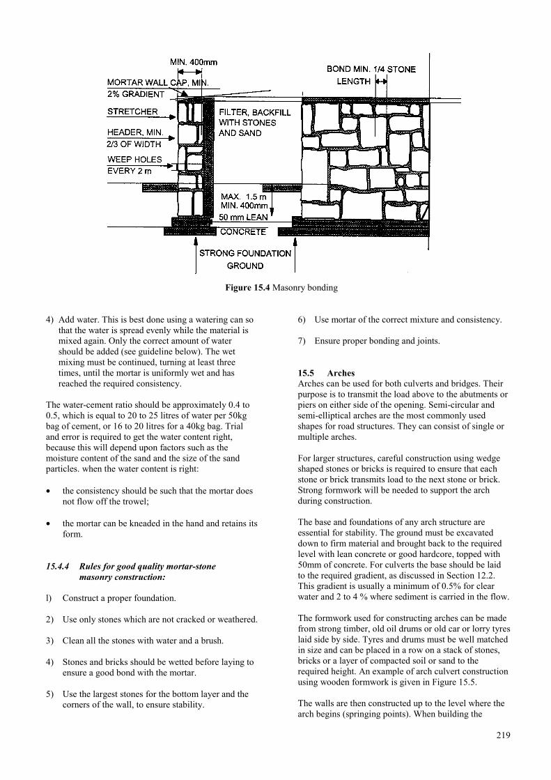
Figure 15.4 Masonry bonding
4) Add water. This is best done using a watering can sothat the water is spread evenly while the material ismixed again. Only the correct amount of watershould be added (see guideline below). The wetmixing must be continued, turning at least threetimes, until the mortar is uniformly wet and hasreached the required consistency.
The water-cement ratio should be approximately 0.4 to0.5, which is equal to 20 to 25 litres of water per 50kgbag of cement, or 16 to 20 litres for a 40kg bag. Trialand error is required to get the water content right,because this will depend upon factors such as themoisture content of the sand and the size of the sandparticles. when the water content is right:
• the consistency should be such that the mortar doesnot flow off the trowel;
• the mortar can be kneaded in the hand and retains itsform.
15.4.4 Rules for good quality mortar-stonemasonry construction:
l) Construct a proper foundation.
2) Use only stones which are not cracked or weathered.
3) Clean all the stones with water and a brush.
4) Stones and bricks should be wetted before laying toensure a good bond with the mortar.
5) Use the largest stones for the bottom layer and thecorners of the wall, to ensure stability.
6) Use mortar of the correct mixture and consistency.
7) Ensure proper bonding and joints.
15.5 ArchesArches can be used for both culverts and bridges. Theirpurpose is to transmit the load above to the abutments orpiers on either side of the opening. Semi-circular andsemi-elliptical arches are the most commonly usedshapes for road structures. They can consist of single ormultiple arches.
For larger structures, careful construction using wedgeshaped stones or bricks is required to ensure that eachstone or brick transmits load to the next stone or brick.Strong formwork will be needed to support the archduring construction.
The base and foundations of any arch structure areessential for stability. The ground must be excavateddown to firm material and brought back to the requiredlevel with lean concrete or good hardcore, topped with50mm of concrete. For culverts the base should be laidto the required gradient, as discussed in Section 12.2.This gradient is usually a minimum of 0.5% for clearwater and 2 to 4 % where sediment is carried in the flow.
The formwork used for constructing arches can be madefrom strong timber, old oil drums or old car or lorry tyreslaid side by side. Tyres and drums must be well matchedin size and can be placed in a row on a stack of stones,bricks or a layer of compacted soil or sand to therequired height. An example of arch culvert constructionusing wooden formwork is given in Figure 15.5.
The walls are then constructed up to the level where thearch begins (springing points). When building the
219
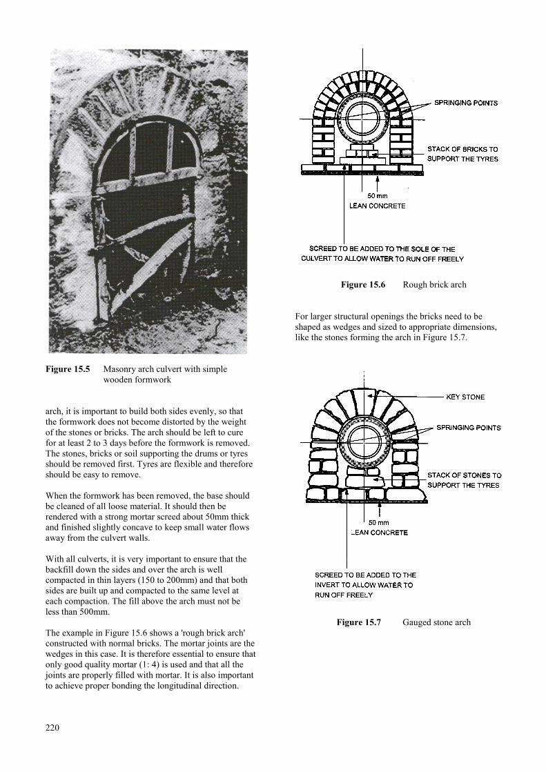
Figure 15.5 Masonry arch culvert with simplewooden formwork
arch, it is important to build both sides evenly, so thatthe formwork does not become distorted by the weightof the stones or bricks. The arch should be left to curefor at least 2 to 3 days before the formwork is removed.The stones, bricks or soil supporting the drums or tyresshould be removed first. Tyres are flexible and thereforeshould be easy to remove.
When the formwork has been removed, the base shouldbe cleaned of all loose material. It should then berendered with a strong mortar screed about 50mm thickand finished slightly concave to keep small water flowsaway from the culvert walls.
With all culverts, it is very important to ensure that thebackfill down the sides and over the arch is wellcompacted in thin layers (150 to 200mm) and that bothsides are built up and compacted to the same level ateach compaction. The fill above the arch must not beless than 500mm.
The example in Figure 15.6 shows a 'rough brick arch'constructed with normal bricks. The mortar joints are thewedges in this case. It is therefore essential to ensure thatonly good quality mortar (1: 4) is used and that all thejoints are properly filled with mortar. It is also importantto achieve proper bonding the longitudinal direction.
220
Figure 15.6 Rough brick arch
For larger structural openings the bricks need to beshaped as wedges and sized to appropriate dimensions,like the stones forming the arch in Figure 15.7.
Figure 15.7 Gauged stone arch
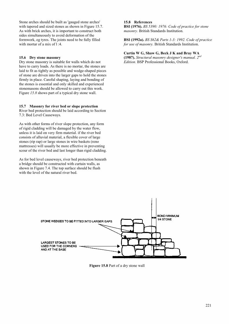
Stone arches should be built as 'gauged stone arches'with tapered and sized stones as shown in Figure 15.7.As with brick arches, it is important to construct bothsides simultaneously to avoid deformation of theformwork, eg tyres. The joints need to be fully filledwith mortar of a mix of l :4.
15.6 Dry stone masonryDry stone masonry is suitable for walls which do nothave to carry loads. As there is no mortar, the stones arelaid to fit as tightly as possible and wedge-shaped piecesof stone are driven into the larger gaps to hold the stonesfirmly in place. Careful shaping, laying and bonding ofthe stones is essential and only skilled and experiencedstonemasons should be allowed to carry out this work.Figure 15.8 shows part of a typical dry stone wall.
15.7 Masonry for river bed or slope protectionRiver bed protection should be laid according to Section7.3: Bed Level Causeways.
As with other forms of river slope protection, any formof rigid cladding will be damaged by the water flow,unless it is laid on very firm material. if the river bedconsists of alluvial material, a flexible cover of largestones (rip rap) or large stones in wire baskets (renomattresses) will usually be more effective in preventingscour of the river bed and last longer than rigid cladding.
As for bed level causeways, river bed protection beneatha bridge should be constructed with curtain walls, asshown in Figure 7.4. The top surface should be flushwith the level of the natural river bed.
15.8 ReferencesBSI (1976). BS 5390: 1976: Code of practice for stonemasonry. British Standards Institution.
BSI (1992a). BS S62& Parts 1-3: 1992. Code of practicefor use of masonry. British Standards Institution.
Curtin W G, Shaw G, Beck J K and Bray WA(1987). Structural masonry designer's manual. 2nd
Edition. BSP Professional Books, Oxford.
Figure 15.8 Part of a dry stone wall
221

222

16 DRAWINGS AND SPECIFICATIONS
16.1 Drawing number 1: site plan and longitudinal section ……………………………………………………... 227
16.1.1 The site plan, drawn to a scale of about 1:500 ………………………………………………….. 227
16.1.2 The longitudinal section, drawn to the same horizontal scale ………………………………….. 227
16.2 Drawing number 2: bridge plan and sections ………………………………………………………………. 227
16.3 Drawing number 3: substructure details ……………………………………………………………………. 227
16.4 Drawing number 4: superstructure main details ……………………………………………………………. 227
16.5 Further detailing …………………………………………………………………………………………….. 227
223

224
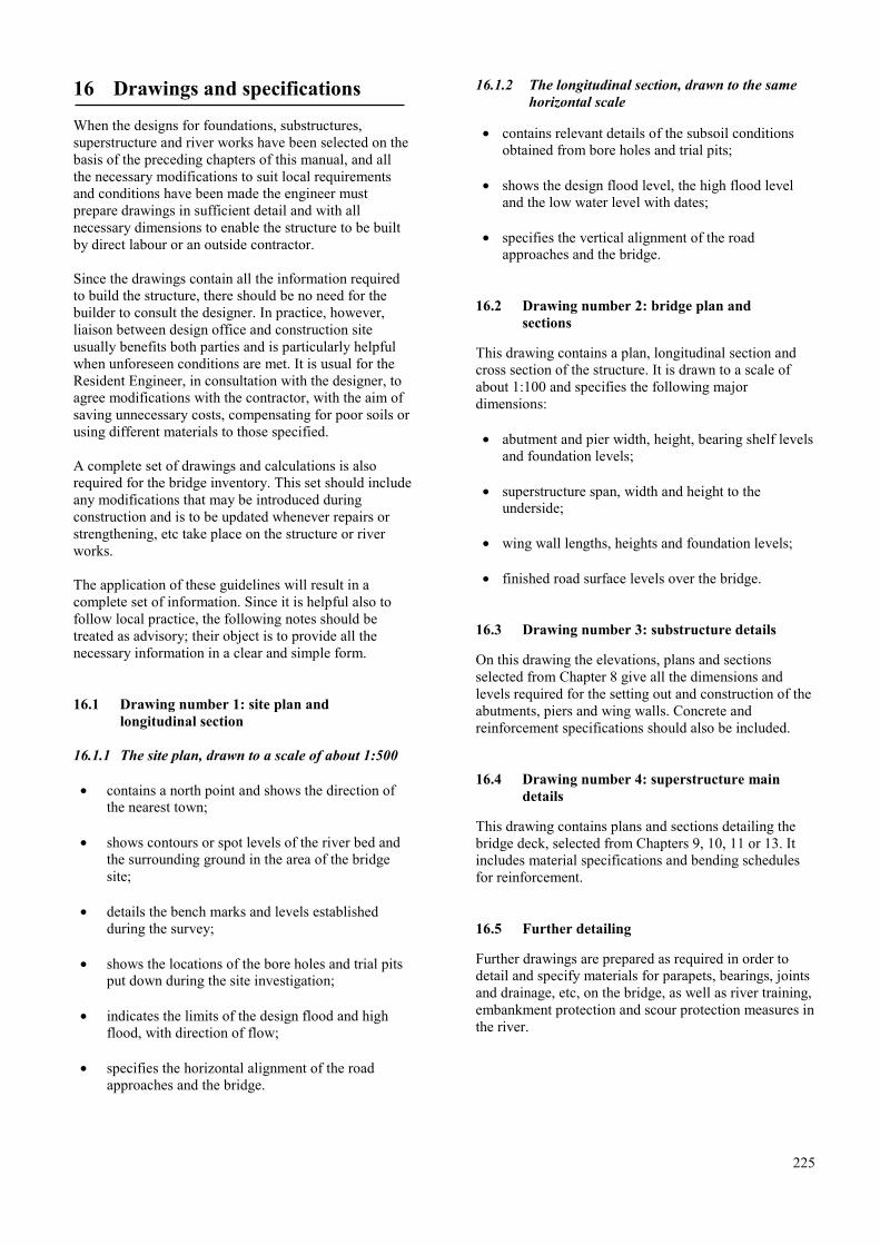
16 Drawings and specifications
When the designs for foundations, substructures,superstructure and river works have been selected on thebasis of the preceding chapters of this manual, and allthe necessary modifications to suit local requirementsand conditions have been made the engineer mustprepare drawings in sufficient detail and with allnecessary dimensions to enable the structure to be builtby direct labour or an outside contractor.
Since the drawings contain all the information requiredto build the structure, there should be no need for thebuilder to consult the designer. In practice, however,liaison between design office and construction siteusually benefits both parties and is particularly helpfulwhen unforeseen conditions are met. It is usual for theResident Engineer, in consultation with the designer, toagree modifications with the contractor, with the aim ofsaving unnecessary costs, compensating for poor soils orusing different materials to those specified.
A complete set of drawings and calculations is alsorequired for the bridge inventory. This set should includeany modifications that may be introduced duringconstruction and is to be updated whenever repairs orstrengthening, etc take place on the structure or riverworks.
The application of these guidelines will result in acomplete set of information. Since it is helpful also tofollow local practice, the following notes should betreated as advisory; their object is to provide all thenecessary information in a clear and simple form.
16.1 Drawing number 1: site plan andlongitudinal section
16.1.1 The site plan, drawn to a scale of about 1:500
• contains a north point and shows the direction ofthe nearest town;
• shows contours or spot levels of the river bed andthe surrounding ground in the area of the bridgesite;
• details the bench marks and levels establishedduring the survey;
• shows the locations of the bore holes and trial pitsput down during the site investigation;
• indicates the limits of the design flood and highflood, with direction of flow;
• specifies the horizontal alignment of the roadapproaches and the bridge.
16.1.2 The longitudinal section, drawn to the samehorizontal scale
• contains relevant details of the subsoil conditionsobtained from bore holes and trial pits;
• shows the design flood level, the high flood leveland the low water level with dates;
• specifies the vertical alignment of the roadapproaches and the bridge.
16.2 Drawing number 2: bridge plan andsections
This drawing contains a plan, longitudinal section andcross section of the structure. It is drawn to a scale ofabout 1:100 and specifies the following majordimensions:
• abutment and pier width, height, bearing shelf levelsand foundation levels;
• superstructure span, width and height to theunderside;
• wing wall lengths, heights and foundation levels;
• finished road surface levels over the bridge.
16.3 Drawing number 3: substructure details
On this drawing the elevations, plans and sectionsselected from Chapter 8 give all the dimensions andlevels required for the setting out and construction of theabutments, piers and wing walls. Concrete andreinforcement specifications should also be included.
16.4 Drawing number 4: superstructure maindetails
This drawing contains plans and sections detailing thebridge deck, selected from Chapters 9, 10, 11 or 13. Itincludes material specifications and bending schedulesfor reinforcement.
16.5 Further detailing
Further drawings are prepared as required in order todetail and specify materials for parapets, bearings, jointsand drainage, etc, on the bridge, as well as river training,embankment protection and scour protection measures inthe river.
225

226

INDEX
Term Section No.
Abutments ………………………………………………………………………………8.1abutment design ………………………………………………………………………... 8.4abutments - mass concrete …………………………………………………………… 8.4.1abutments - reinforced concrete ……………………………………………………….84.3abutments - temporary bridges ……………………………………………………….. 13.3abutments- timber decks ……………………………………………………………… 11.5afflux ……………………………………………………………………………………5.5aggressive chemicals …………………………………………………………………... 3.5aprons …………………………………………………………………………. 6.2.1, 6.2.2arches …………………………………………………………………………………. 15.5backwater ………………………………………………………………………………. 5.5bearing material ………………………………………………………………………. 14.5bearing pressures ………………………………………………………………………. 8.3bearing shelves ………………………………………………………………………..8.4.6bearings ………………………………………………………………….9.2.2, 10.26, 14.6bed level causeways …………………………………………………………………… 7.3bores - cable percussion ………………………………………………………………3.1.3bores - hand auger …………………………………………………………………….3.1.2bores-rotary drilling ………………………………………………………………….. 3.1.4bridge height …………………………………………………………………………… 5.2bridges-log ……………………………………………………………………………. 11.1bridges - skew ………………………………………………………………………... 2.1.2bridges - submersible ………………………………………………………………….. 7.5bridges - temporary …………………………………………………………………….. 13bridges - timber beam ………………………………………………………………… 11.2catchment …………………………………………………………………………….. 2.2.1concrete ………………………………………………………………………………. 14.1construction joints …………………………………………………………….9.2.4, 10.2.8cross-sections ………………………………………………………………………….. 2.3culverts …………………………………………………………………………………. 12culverts - concrete box ………………………………………………………………...12.6culverts - concrete pipe ……………………………………………………………….. 12.4culverts - erosion control ………………………………………………………………12.1culverts - flexible steel ………………………………………………………………...12.5culverts - headwalls …………………………………………………………………... 12.3culverts - location & alignment ………………………………………………………..12.2curtain walls …………………………………………………………………………….7.3decks ………………………………………………………………………………. 9,10,11design flood ……………………………………………………………………………….5design life ……………………………………………………………………………….2.4design standards ……………………………………………………………………2.8, 9.1discharge ……………………………………………………………………………….. 4.2drainage …………………………………………………………………….. 9.2.6, 10.2.10drawings …………………………………………………………………………………16
227

Term Section No.
earthquake restraint ……………………………………………………………………..8.7field tests …………………………………………………………………………….. 3.4.1.filter blankets ………………………………………………………………………….6.1.3flow velocity …………………………………………………………………………… 4.1flow volume ……………………………………………………………………………. 4.2footpaths ………………………………………………………….. 2.7,9.2.10,10.2.12,11.4fords ……………………………………………………………………………………. 7.2foundations ………………………………………………………………………………. 8gabions ……………………………………………………………………………….. 6.1.2geophysical surveying ………………………………………………………………...3.1.5groynes ………………………………………………………………………………. 6.2.4guide banks …………………………………………………………………………... 6.2.3hydraulic design …………………………………………………………………………..5hydraulics - abutments, piers …………………………………………………………... 5.3Term ………………………………………………………………………….. Section No.hydraulics - culverts …………………………………………………………………… 5.6joint sealant …………………………………………………………………………… 14.6joints - construction ………………………………………………………………….. 9.2.4joints - expansion ……………………………………………………………. 9.2.3, 10.2.7loading - design ………………………………………………………………………... 2.8longitudinal section ……………………………………………………………… 2.3, 16.1low level crossings ………………………………………………………………………. 7low water crossings, signs & markers …………………………………………………. 7.6masonry - Stone or brick ………………………………………………………………...15materials, concrete, steel, etc …………………………………………………………… 14mortar ………………………………………………………………………………..15.4.4navigational requirements ……………………………………………………………2.2.3.parapets …………………………………………………………………….. 9.2.7, 10.2.11pedestrians/cyclists ……………………………………………... 2.7, 9.2.10, 10.2.12, 11.4penetration test ………………………………………………………………………..3.4.1piers ……………………………………………………………………………….. 8.2, 8.5piled walls ……………………………………………………………………………. 6.1.4planning ………………………………………………………………………………….. 2plans …………………………………………………………………………………….. 16plate bearing test …………………………………………………………………….. 3.4.1prefabricated bridge decks ………………………………………………………….. 13.2.4protection methods …………………………………………………………………….. 6.2protection methods - banks ………………………………………………………….. 6.2.2protection methods - foundations ……………………………………………………. 6.2.1protection methods - groynes ………………………………………………………... 6.2.4protection methods - guide banks ……………………………………………………. 6.2.3protection methods - temporary structures …………………………………………….13.4raff foundations ……………………………………………………………………….8.4.5reinforcement ……………………………………………………………… 8, 9.2.5, 10.2.9reinforcement, steel ……………………………………………………………………14.2Reno mattresses ……………………………………………………………………… 6.1.2Resources ……………………………………………………………………………… 2.9
228

Term Section No.
retaining walls, mass concrete ……………………………………………………….. 8.4.2retaining walls, reinforced concrete …………………………………………………..8.4.4rip rap …………………………………………………………………………………6.1.1river hydraulics …………………………………………………………………………... 4river morphology …………………………………………………………………….. 2.1.1river works ……………………………………………………………………………….. 6run-on slabs ……………………………………………………………………………. 8.8sampling ……………………………………………………………………………….. 3.3scour …………………………………………………………………………………… 5.4scour protection …………………………………………………………………. 6.1.5, 6.2services ………………………………………………………………………………. 9.2.9shear connectors ……………………………………………………………………. 10.2.3signs ……………………………………………………………………………………. 7.6site investigations ………………………………………………………………………... 3site plan ……………………………………………………………………………….. 16.1soil sampling …………………………………………………………………………… 3.3soil testing ……………………………………………………………………………… 3.4specifications …………………………………………………………………………… 16steel beams …………………………………………………………………………….14.3steel - protective treatment …………………………………………………………..10.2.4stone pitching …………………………………………………………………………6.1.6substructures ……………………………………………………………………………... 8substructures - temporary bridges ……………………………………………………..13.3superstructures - composite …………………………………………………………….. 10superstructures - concrete ……………………………………………………………….. 9superstructures - emergency ……………………………………………………………. 13superstructures - timber ………………………………………………………………… 11superstructures - vertical profile ……………………………………………... 9.2.1, 10.2.1surfacing ……………………………………………………………………………... 9.2.8test pits ………………………………………………………………………………...3.1.1timber classification …………………………………………………………………14.4.2timber decks …………………………………………………………………………...11.3timber - protective treatment ……………………………………………………….. 14.4.1timber - structural …………………………………………………………………….. 14.4timber superstructure …………………………………………………………………… 11traffic …………………………………………………………………………………... 2.5vegetation - scour protection ………………………………………………………… 6.1.5vented causeways ……………………………………………………………………… 7.4water levels …………………………………………………………………………... 2.2.3width …………………………………………………………………………………… 2.6wingwalls ………………………………………………………………………………. 8.1
229

230

ISSN 0951-8797
OS-F
A d
esig
n m
anua
l for
smal
l bri
dges
OR
N 9