design-in sheet hid-av 35-70w/s cdm · web viewoutdoor electronics gear are 4kv protected but the...
TRANSCRIPT
DESIGN IN SHEET
HID-PV C 35-50-70 /I/C CDM
Philips Lighting ElectronicsGDC Eindhoven
Author: Sjef JansenMarch 2012
9137-006-53166 sh-460 2012-03-29
- 1 - HID
-PV
C 35
-50-
70 /I
/C C
DM
913
7-00
6-53
166
sh-4
60 2
012-
03-2
9
DESIGN IN SHEET
HID-PV C 35-50-70 /I/C CDMContents
1. Introduction 32. Version management 33. Ordering 34. Dimensions 35. Temperature behaviour 46. Wiring 67. Electro-Magnetic Compatibility 78. Factory handling 89. Installation / Mounting 910. Operating in abnormal conditions 1111. Advised communication 1112. Frequently Asked Questions 1213. For more information 12
- 2 - HID
-PV
C 35
-50-
70 /I
/C C
DM
913
7-00
6-53
166
sh-4
60 2
012-
03-2
9
DESIGN IN SHEET
HID-PV C 35-50-70 /I/C CDM1. Introduction
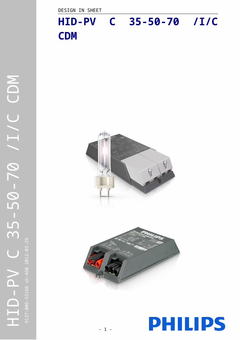
The PrimaVision Compact family has been extended to include Connector version as well. The PrimaVision Connector 35W, 50W and 70W fulfil to CISPR 15 ed 7.2. The new drivers have the same footprint as their predecessors to allow easy design-in.
2. Version management
This is the design-in sheet for the PrimaVision Compact 35 /C, 50 /C and 70 /Cdrivers.Status of the product: Sampling
13-10-2010: 9137-006-531 sht-460 2010-10-13Added PrimaVision Compact 50 /I22-01-2010: 9137-006-531 sht-460 2010-04-21Initial document29-03-2012: 9137-006-531 sht-460 2010-04-21Added PrimaVision Compact 35/C, 50/C and 70/C
3. Ordering
Technical name: HID-PV C 35 /I CDM HID-PV C 35 /C CDM12NC: 9137 006 53166 9137 006 84466EAN3: 8727900859737 tbdEOC: 872790085973700 tbd
Technical name: HID-PV C 50 /I CDM HID-PV C 50 /C CDM 12NC: 9137 006 65166 9137 006 84566EAN3: 8727900933666 tbdEOC: 872790093365900 tbd
Technical name: HID-PV C 70 /I CDM HID-PV C 70 /C CDM12NC: 9137 006 53266 9137 006 84666EAN3: 8727900859881 tbdEOC: 872790085988100 tbd
Product Qtybox/pallet
Net. weight(kg)
Box Dim. LxWxH (mm)
Pallet Dim.LxWxH (mm)
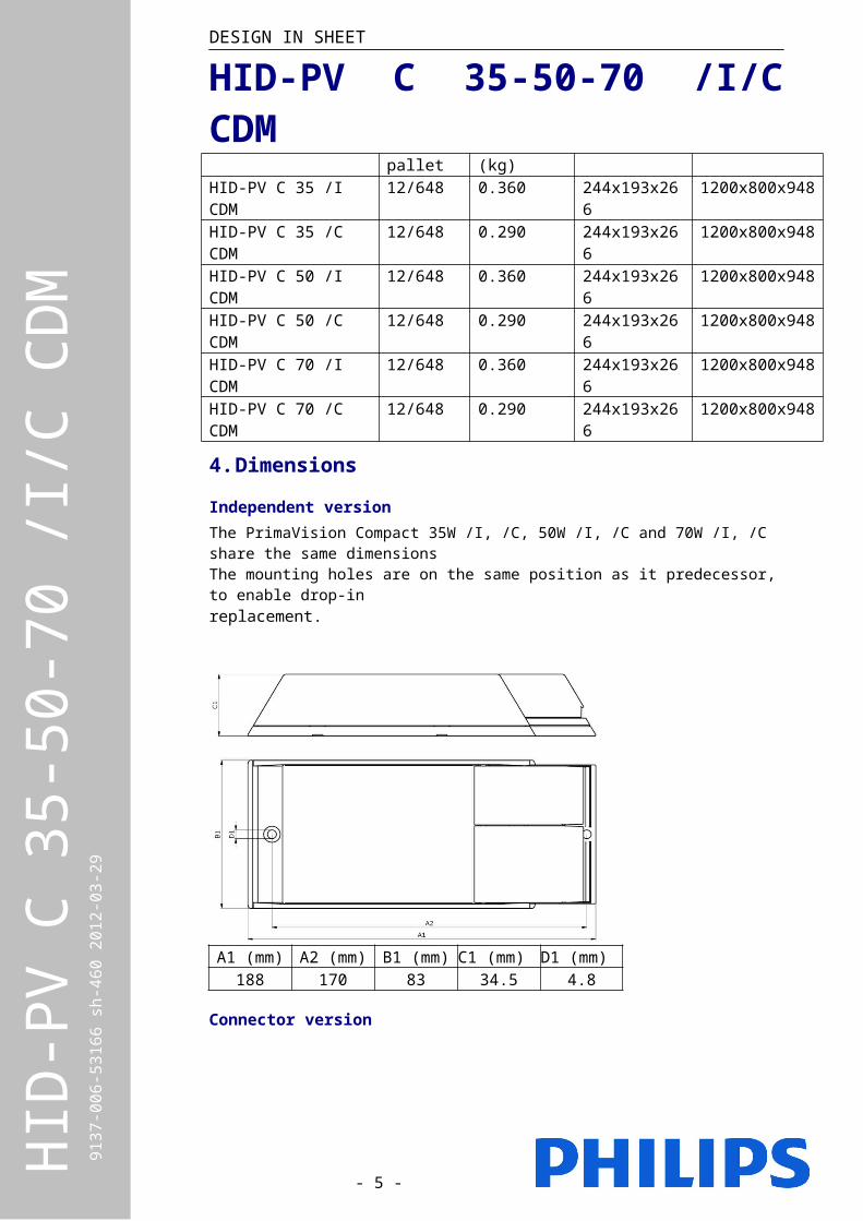
HID-PV C 35 /I CDM 12/648 0.360 244x193x266 1200x800x948HID-PV C 35 /C CDM 12/648 0.290 244x193x266 1200x800x948HID-PV C 50 /I CDM 12/648 0.360 244x193x266 1200x800x948HID-PV C 50 /C CDM 12/648 0.290 244x193x266 1200x800x948HID-PV C 70 /I CDM 12/648 0.360 244x193x266 1200x800x948HID-PV C 70 /C CDM 12/648 0.290 244x193x266 1200x800x948
4. Dimensions
Independent versionThe PrimaVision Compact 35W /I, /C, 50W /I, /C and 70W /I, /C share the same dimensionsThe mounting holes are on the same position as it predecessor, to enable drop-inreplacement.
- 3 - HID
-PV
C 35
-50-
70 /I
/C C
DM
913
7-00
6-53
166
sh-4
60 2
012-
03-2
9
DESIGN IN SHEET
HID-PV C 35-50-70 /I/C CDM
A1 (mm) A2 (mm) B1 (mm) C1 (mm) D1 (mm)188 170 83 34.5 4.8
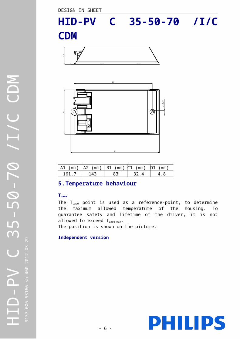
Connector version
A1 (mm) A2 (mm) B1 (mm) C1 (mm) D1 (mm)161.7 143 83 32.4 4.8
5. Temperature behaviour
Tcase
The Tcase point is used as a reference-point, to determine the maximum allowed temperature of the housing. To guarantee safety and lifetime of the driver, it is not allowed to exceed Tcase max.
- 4 - HID
-PV
C 35
-50-
70 /I
/C C
DM
913
7-00
6-53
166
sh-4
60 2
012-
03-2
9
DESIGN IN SHEET
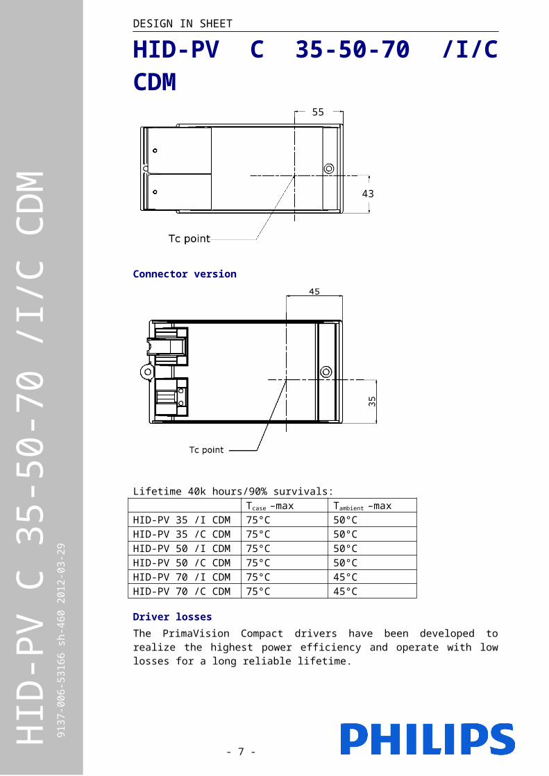
HID-PV C 35-50-70 /I/C CDMThe position is shown on the picture.
Independent version
Connector version
Lifetime 40k hours/90% survivals:Tcase –max Tambient –max
HID-PV 35 /I CDM 75°C 50°CHID-PV 35 /C CDM 75°C 50°CHID-PV 50 /I CDM 75°C 50°CHID-PV 50 /C CDM 75°C 50°CHID-PV 70 /I CDM 75°C 45°CHID-PV 70 /C CDM 75°C 45°C
Driver lossesThe PrimaVision Compact drivers have been developed to realize the highest power efficiency and operate with low losses for a long reliable lifetime.
Temperature TestingBecause the driver will regulate the lamp to a constant power, the input current will increase when the input voltage is lower. This ultimately will influence the
- 5 - HID
-PV
C 35
-50-
70 /I
/C C
DM
913
7-00
6-53
166
sh-4
60 2
012-
03-2
9
55
43
DESIGN IN SHEET
HID-PV C 35-50-70 /I/C CDMpower losses, so the worst-case temperature should therefore be measured at lowest mains voltage of 198V.
To guarantee, that the maximum value of Tcase. is not exceeded, a thermo-couple should be mounted on the Tc point of the driver.
For more information about lifetime and temperature please consult the HID application guide.
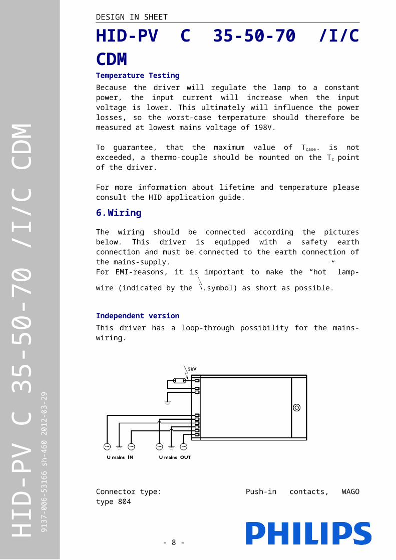
6. Wiring
The wiring should be connected according the pictures below. This driver is equipped with a safety earth connection and must be connected to the earth connection of the mains-supply.
For EMI-reasons, it is important to make the “hot” lamp-wire (indicated by the .symbol) as short as possible.
Independent versionThis driver has a loop-through possibility for the mains-wiring.
Connector type: Push-in contacts, WAGO type 804Wire cross section: 0.75-2.5 mm² massive or strandedStrip length: 10-11mmMax cable capacitance lamp-wires: 150 pFMaximum length lamp-wires: 2.0m
- 6 - HID
-PV
C 35
-50-
70 /I
/C C
DM
913
7-00
6-53
166
sh-4
60 2
012-
03-2
9
DESIGN IN SHEET
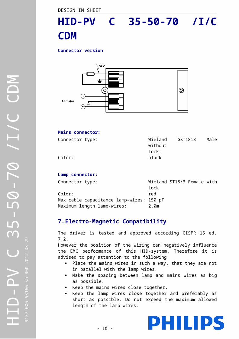
HID-PV C 35-50-70 /I/C CDMConnector version
Mains connector:Connector type: Wieland GST18i3 Male without
lock.Color: black
Lamp connector:Connector type: Wieland ST18/3 Female with lockColor: redMax cable capacitance lamp-wires: 150 pFMaximum length lamp-wires: 2.0m
7. Electro-Magnetic Compatibility
The driver is tested and approved according CISPR 15 ed. 7.2.However the position of the wiring can negatively influence the EMC performance of this HID-system. Therefore it is advised to pay attention to the following:
Place the mains wires in such a way, that they are not in parallel with the lamp wires.
Make the spacing between lamp and mains wires as big as possible. Keep the mains wires close together. Keep the lamp wires close together and preferably as short as possible.
Do not exceed the maximum allowed length of the lamp wires.
- 7 - HID
-PV
C 35
-50-
70 /I
/C C
DM
913
7-00
6-53
166
sh-4
60 2
012-
03-2
9
DESIGN IN SHEET
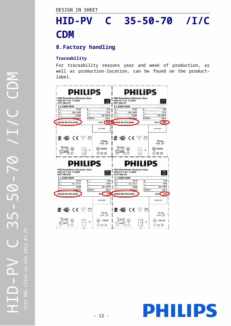
HID-PV C 35-50-70 /I/C CDM8. Factory handling
TraceabilityFor traceability reasons year and week of production, as well as production-location, can be found on the product-label.
- 8 - HID
-PV
C 35
-50-
70 /I
/C C
DM
913
7-00
6-53
166
sh-4
60 2
012-
03-2
9
DESIGN IN SHEET
HID-PV C 35-50-70 /I/C CDMThe production-code consists of production year and week.
Example: If a product has been marked 0810 : Position 1 and 2 are the last digits from the year of production. The digits
08 indicates that the product has been made in 2008 Position 3 and 4 indicate the week of production. The number 10
indicates that the product has been made in week 10. Furthermore, each product has a serial number, including barcode. (This
is depending of the production-location)
9. Installation / Mounting
Lamps that can be driven by the driverDriver LampHID-PV C 35W /IHID-PV C 35W /C
All CDM 35W lamps, excluding: CDM-Tm PGJ5 35W lamps
HID-PV C 50W /IHID-PV C 50W /C
All CDM 50W lamps
HID-PV C 70W /IHID-PV C 70W /C
All CDM 70W lamps
The drivers are not compatible with the following lamps: Metal halide quartz lamps
Suitable application for this driverThis product is designed mainly for applications that are working in an Indoor environment (IP23 or superior casing).Typical applications are:
Spot and accent lighting Downlighting and general lighting Mini flood lighting Main segment is retail (shops) Secondary segments are office and health care
The PrimaVision Compact range is not intended for Outdoor use due to the following outdoor constraints:
High humidity and condensation risks Vibrations e.g. when the luminaire is mounted on a public lighting pole Lightning surges on the mains. Outdoor electronics gear are 4kV
protected but the HID-PV C 35W/50W/70W is protected up to 2kV.
Therefore, it is the responsibility of the luminaire manufacturer and the installer to take into account the above and implement adequate protection for the above. Here are some requirements for Outdoor applications:
Place the gear in an IP54 or higher environment Avoid placing the gear or luminaire in high poles Place adequate Lightning protection in the lighting installation Planner should take it into account for Cost of Ownership calculations and
maintenance plans.
If the above points are not taken into account in the design and the installation, Philips will have the option not to apply the standard guarantee.
- 9 - HID
-PV
C 35
-50-
70 /I
/C C
DM
913
7-00
6-53
166
sh-4
60 2
012-
03-2
9
DESIGN IN SHEET
HID-PV C 35-50-70 /I/C CDMMaximum number of gear per MCBThe maximum number of drivers, which can be connected to a B type 16A is 24x35W, 24x 50W or 20x 70W. For other types apply conversion table below:
Conversion table for max. Quantities of driver on other typesof Miniature Circuit Breaker
Remark: L, G and U are old type MCB.
DC-operationThis driver is not designed for DC operation.
MountingThe strain reliefs can be closed by means of 2 (pre-assembled) slotted crosshead screws of the PZ1 type. The maximum allowed torque for mounting the screws is 1.0Nm.
There are several methods to install the driver: The driver can be mounted on a solid surface by means of 2 M4 screws. The driver can be placed on the ceiling, without any means to fix it. (It is
advised, not to place the driver upside down) A metal hook can be applied to one of the mounting holes of the driver, to
hang it on the construction of the ceiling. (it is advised to have the wires/connectors facing down)
- 10 - HID
-PV
C 35
-50-
70 /I
/C C
DM
913
7-00
6-53
166
sh-4
60 2
012-
03-2
9
DESIGN IN SHEET
HID-PV C 35-50-70 /I/C CDMIn all this situations, it is important not to cover the driver by any (isolating) material.
10. Operating in abnormal conditions
Active Thermal protectionIf the driver is used at a too high temperature an internal thermal protection willprotect the driver against damage; the driver will switch off the lamp. Mainsvoltage needs to be reset in order to reset thermal protection.The thermal protection becomes active at Tcase > 95°C.
Mains voltageThe gear is designed to operate within a operational/safety range of 180-264V. However the performance is guaranteed within the performance range of 198-254V. Within this range, the lamp power is regulated within 3% of its nominal power. (Valid for a lamp voltage between 80 and 90V)
Over voltageThe driver has a limited protection against over voltage, it is advised to preventhigher mains voltages than +10%. This will however negatively influence thelifetime and reliability.
Lightning and power surgesProtection against surges because of lightning are built in the gear.IEC61547, surge levels: 1.0kV Line to Line and 2.0kV Line to GND
End Of Life (EOL) lamp protectionThe driver has a protection against an End Of Life Lamp. The driver will detect the failing lamp and switch to standby. After re-lamping, the mains has to be switched off and on, in order to reset the driver.
Mains dipsIf mains dips occur that cause the lamp to extinguish, the driver will automaticallyre-ignite the lamp for a maximum of three times after a cooling-down period ofapproximately 10 minutes. After the last attempt the mains power needs to becycled to reset the internal ignition timer of the driver.
11. Advised communication
Philips Lighting Electronics advises to communicate the following information to your customers via your preferred media: Catalogues, brochures, Product datasheets, Mounting instructions, Internet and Intranet.
TechnicalDue to lamp characteristics, this driver needs some time to re-ignite (10…15 minutes) after switch-off.When the lamp has reached end of life, the driver will switch off the lamp in order to avoid lamp overheating. After lamp replacement, the mains voltage will have to be reset and the system will work normally. The driver does not need to be replaced. The PrimaVision driver range is equipped with an internal thermal-sensor, that will prevent loss of driver lifetime due to overheating in the luminaire/installation.Marketing
- 11 - HID
-PV
C 35
-50-
70 /I
/C C
DM
913
7-00
6-53
166
sh-4
60 2
012-
03-2
9
DESIGN IN SHEET
HID-PV C 35-50-70 /I/C CDMThe use of PrimaVision Compact in your luminaire will provide your customer thefollowing benefits:• Optimum system performanceDevelopment of CDM lamps and driver is in one hand. Every product istested extensively, requiring a million burning hours before a system canbe released. The result is an optimal light performance with PhilipsMASTERColour CDM lamps.• Flicker free operation• 30 to 40% longer lamp lifetime• 10% energy saving compared to a Electromagnetic system• Safe and comfortable behaviour when lamp reaches End of LifeFurthermore, the PrimaVision Compact range has low losses, which guaranteesmaximum energy savings and limit heat generation, translating into a longer driver lifetime.
GuaranteeThe guarantee of 3 and 5 years for Philips Electronics is applicable for this product. For more information about guarantee, please visit our website: www.philips.com/ehid
12. Frequently Asked Questions
Is the new HID-PV Compact Independent compatible with the existinggeneration?Yes. The outer dimensions of the PrimaVision Compact I are the same as thepredecessor; enabling drop-in replacement.The EMC performance is complying with the new CISPR 15 ed 7.2 requirements.Does the HID-PV Compact Independent also offer SOFT START?No, this feature is only available in AspiraVision range.Does the HID-PV Compact Independent offer the possibility for loopthroughmains wiring?No, this feature is only available in the AspiraVision-range.The housing is plastic. Does this give problems with EMC or temperature?No, the gear is specially developed for the housing. Therefore, no problems withEMC and temperature occur.
13. For more information
Please contact your local sales representative.Check OEM application guide for general information about electronic gear.Visit our web-site www.philips.com/ehid
- 12 - HID
-PV
C 35
-50-
70 /I
/C C
DM
913
7-00
6-53
166
sh-4
60 2
012-
03-2
9