design guidelines division 22 plumbing
TRANSCRIPT

DESIGN GUIDELINES
Division 22 – PLUMBING
Release 3.0 April 2017 Released by: Cleveland Clinic Facilities and Construction 9500 Euclid Ave. Cleveland OH 44195
All information within this Document is considered CONFIDENTIAL and PROPRIETARY. By receipt and use of this Document, the recipient agrees not to divulge any of the information herein and attached hereto to persons other than those within the recipients’ organization that have specific need to know for the purposes of reviewing and referencing this information. Recipient also agrees not to use this information in any manner detrimental to the interests of Cleveland Clinic.

Cleveland Clinic
Design Guidelines Copyright © 2017
By Cleveland Clinic These Specifications, or parts thereof, may not be reproduced in any form without the permission of Cleveland Clinic.

Cleveland Clinic
Cleveland Clinic Design Guidelines: Division 22 - Plumbing
The following pages contain guidelines for the design and construction of new and
renovated facilities at all domestic Cleveland Clinic locations. They shall be used by A/E
firms in the preparation of drawings and specifications for construction of facilities.
The general purpose of each Design Guideline is to provide minimal criteria for
construction materials and equipment at Cleveland Clinic facilities regarding Codes and
FM Global compliance, warranty, approved products, execution, and uniformity.
The Guidelines are not Contract Specifications, but are used to prepare more detailed,
project-specific specifications. The Guidelines are intended to be used to address system
design aspects of equipment that Cleveland Clinic desires to standardize among facilities,
and identify prohibited materials and construction practices.
The use of these Guidelines is mandatory for all design or maintenance projects. Deviations
are discouraged. If project conditions arise which require a deviation, it shall be thoroughly
documented by the user and submitted to Cleveland Clinic for review and approval using
the Design Standard Deviation Request Form.

DESIGN STANDARDS WAIVER REQUEST FORM
From:
Department or Firm:
Phone:
E-mail:
Date:
Standard Name:
Specification, Guideline, or Detail Number:
Section, Page, Paragraph Number(s) or Detail Number:
BRIEF DESCRIPTION OF WAIVER:
DESCRIBE REASON FOR WAIVER:
HAS THIS REQUEST BEEN DISCUSSED WITH CC STAFF? IF SO PLEASE PROVIDE
NAME OF PERSON:
APPROVED APPROVED WITH COMMENTS NOT APPROVED
COMMENTS:
SIGN: DATE:
Bottom Portion for Design Standards Review Committee

Design Guidelines: Division 22 – Plumbing
1. Plumbing Drawing and Equipment Naming Requirements
2. Domestic Water Distribution
3. Sanitary Waste
4. Storm Drainage
5. Domestic Water Heating Equipment
6. Plumbing Fixtures
7. Plumbing Insulation and Labeling
8. Gas and Vacuum Systems
9. Facility Natural Gas Piping
10. Laboratory Water and Waste Systems
** End of List **

Cleveland Clinic Design Standards Plumbing Systems Design Guidelines 1. Plumbing Drawing and Equipment Naming Requirements
April 2017 1 - 1
1.1 Plumbing Drawing Requirements
A. The following drawing naming structure shall be followed on all projects. Naming structure shall
supersede all architectural naming structures. If conflict exists with architectural naming, discuss
with project team. The goal of a structured naming convention is that all drawings, regardless of
project type and project team, shall be consistent and searchable for Cleveland Clinic staff.
B. Follow naming structure most applicable to project size. Not all drawing numbers will be required
for every job.
Large Project
Drawing Series Drawing Content Sample Drawing Name
P-0XX General Notes & Legend Plumbing General Notes and Symbol Legend
PD-XXX Demolition Plumbing xx Floor Demolition Plan
P-1XX Sanitary and Storm Drainage Plumbing xx Floor Drainage Plan
P-2XX Domestic Water Plumbing xx Floor Domestic Water Plan
P-3XX Medical Gas xx Floor Medical Gas Plan
P-4XX Sections Sections
P-5XX Details Plumbing Details
P-6XX Schedules Plumbing Schedules
P-7XX Flow Diagrams & Isometrics Plumbing Isometric Diagrams
P-8XX Miscellaneous (Enlarged Plans, etc.) Enlarged xx Floor Plan
M-9XX* Temperature Control Diagrams and
Sequences -
*Include Plumbing Temperature Control Diagrams on Mechanical Drawing Series M9-XXX
Small Project
To avoid creating unnecessary sheets (e.g., separate plumbing sheets for single sink
replacement), combining mechanical and plumbing scope on a single sheet is acceptable,
provided mechanical and plumbing scope each have a unique plan on that sheet.
When combined plumbing sheets are utilized, at a minimum the following sheets shall be
utilized: P-0XX, P-1XX, and P-6XX
On combined sheets, all disciplines shall be named in title block, making it easily
searchable (e.g., Partial 1st Floor Plumbing and Medical Gas Plan).
Drawing Series Drawing Content Sample Drawing Name
P-0XX General Notes, Legend, & Specifications Plumbing General Notes, Symbol
Legend and Specifications
PD-XXX
Demolition
If project is small enough, demolition
scope can be included on P-1XX
Plumbing xx Floor Demolition Plan
P-1XX Plumbing & Medical Gas Plumbing xx Floor Plumbing Plans
P-5XX Details Plumbing Details
P-6XX Schedules, Diagrams & Isometrics Plumbing Schedules and Diagrams
C. Indicate all applicable codes followed on General Notes Sheet (P-001).

Cleveland Clinic Design Standards Plumbing Systems Design Guidelines 1. Plumbing Drawing and Equipment Naming Requirements
April 2017 1 - 2
1.2 Equipment Naming Requirements
A. The following plumbing equipment nomenclature shall be used to identify all plumbing
equipment.
Plumbing Equipment Type Equipment Tag
Area Drain AD
Backflow Preventer BFP
Clinic Sink CS
Domestic Water Heater DWH
Domestic Booster Pump DBP
Emergency Eyewash Fountain EEW
Emergency Shower ES
Emergency Shower/Eyewash ESE
Electric Water Cooler EWC
Floor Drain FD
Floor Sink FS
Frost-Proof Wall Hydrant FPWH
Frost-Proof Ground Hydrant FPGH
Frost-Proof Roof Hydrant FPRH
Grease Interceptor GI
Grease Trap GT
Hose Bibb HB
Lavatory L
Mop Basin MB
Pressure Regulating Valve PRV
Recirculating Hot Water Pump RHWP
Roof Drain RD
Shower SH
Sink S
Sewage Ejector SE
Sump Pump SP
Temperature Mixing Valve TMV
Urinal U
Wall Box WB
Water Closet WC

Cleveland Clinic Design Standards Plumbing Systems Design Guidelines 1. Plumbing Drawing and Equipment Naming Requirements
April 2017 1 - 3
Medical Gas Equipment Type Equipment Tag
Area Alarm Panel AAP
Master Alarm Panel MAP
Medical Air Compressor MAC
Medical Vacuum Pump MVP
Zone Valve Box ZVB
B. The following plumbing piping labels shall be used to identify all piping on design drawings.
Plumbing Piping System Piping Label
Compressed Air Piping CA
Acid Vent Piping AV
Acid Waste Piping AW
Carbon Dioxide Piping CO2
Deionized Water Piping DE
Domestic Cold Water Piping CW
Domestic Hot Water Piping HW
Domestic Recirculating Hot Water Piping RHW
Equipment Air Piping EQA
Instrument Air Piping IA
Medical Air Piping MA
Medical Air Intake Piping MAI
Medical Vacuum Piping MV
Medical Vacuum Discharge Piping MVD
Natural Gas Piping NG
Nitrogen Piping N2
Nitrous Oxide Piping N2O
Non-Potable Cold Water Piping NPCW
Non-Potable Hot Water Piping NPHW
Non-Potable Recirculating Hot Water Piping NPRHW
Oxygen Piping O2
Overflow Storm Piping OST
Purified Water Piping PW
Sanitary Sewer SAN
Storm Sewer ST
Tempered Hot Water Piping THW
Vent Piping V
Waste Anesthetic Gas Disposal WAGD
140°F Hot Water Piping 140°F HW
140°F Recirculating Hot Water Piping 140°F RHW

Cleveland Clinic Design Standards Plumbing Systems Design Guidelines 2. Domestic Water Distribution
April 2017 2 - 1
1.1 General Domestic Water Distribution Requirements
A. Building domestic water distribution systems shall be metered and isolated from the municipal
water supply in accordance with the municipality’s requirements.
B. The design of building supply and distribution systems shall provide a volume of water at the
required flows, pressures, and temperatures to ensure safe, efficient, and code-compliant
operation during periods of peak demand.
Domestic Water Piping Sizing
System Sizing Criteria (Feet Per Second)
Domestic Cold Water Velocity not to exceed 6 fps
Domestic Hot Water Velocity not to exceed 4 fps
C. Domestic hot water systems shall be designed to reasonably assure an expeditious flow of hot
water at all outlets. Pumped circulating systems are required for all patient care areas. Electric
heat maintenance cable is only acceptable in administration facilities.
1. Size hot water return lines by the heat loss method as outlined in the ASHRAE Systems
and Equipment Data Book, not to exceed 4–5°F heat loss. Developed length of branch
piping from fixture outlet to circulated mains shall not exceed 25 feet with the following
exceptions:
a. Hot water piping serving public lavatory faucets shall be circulated to within 18
inches of the fixture hot water supply stop.
b. Provide a check valve, strainer, and flow control valve at the end of each circuit.
c. A single point-of-use instantaneous electric water heater shall serve no more than
three (3) lavatory faucets. The length of hot water piping from the heater to each
faucet stop shall not exceed 36 inches.
D. Main distribution piping risers shall utilize chases within the building footprint for vertical routing
to multiple floor levels where possible.
E. Provide line shut-off valves at locations required for proper operation, servicing, and
troubleshooting of the domestic water distribution system and connected components. Locations
shall include, but not be limited to, the following:
1. At each fixture and piece of equipment
2. At each branch take-off from mains
3. At the base of each riser
4. At each battery of fixtures, where recommended by equipment manufacturers
5. At strategic locations to allow sectional isolation while limiting disruption of services to
large portions of the system
F. Accessible full size capped valves shall be provided where required for future connections.

Cleveland Clinic Design Standards Plumbing Systems Design Guidelines 2. Domestic Water Distribution
April 2017 2 - 2
G. All valves shall be accessible for operation and servicing. Provide access panels for all concealed
valves. Coordinate the location of access panels with the architectural features of the building,
and obtain approval of locations from the Architect.
H. On new projects and major renovations, a water sample shall be collected and tested. Based on
results of sample, provide all required water treatment to satisfy project’s water requirements.
I. Provide frost-proof wall hydrants with integral vacuum breaker on exterior walls a maximum of
150 feet apart, at loading docks, near building entrances, at mechanical yards, and within 50 feet
of exterior grease interceptors. Hydrants should be located at approximately 18 inches above
finished grade. Coordinate the location of all wall hydrants with the architectural features of the
building, and obtain approval of locations from the Architect.
J. Provide frost-proof wall hydrant with backflow preventer on at least one exterior wall of the roof
penthouse and/or a frost-proof roof hydrant to cover entire roof area. Hydrants shall be located
only where necessary. Coordinate all locations with CC Engineer during design.
K. In each mechanical room, provide a hose bib 24 inches above finished floor with integral vacuum
breaker and a minimum of one floor drain. Provide additional hose bibs located within 100 feet
of adjacent hose bib.
L. Provide accessible check valves in the individual cold and hot water fixture supply lines serving
thermostatic mixing valves or assemblies having hose connection outlets that are not equipped
with integral check stops.
M. Trap priming devices that rely upon line pressure differential shall be used for patient toilet rooms.
Electronic trap priming devices shall be used in mechanical rooms and provided with an
accessible/serviceable strainer immediately upstream of the device solenoid valve.
N. Static pressure at plumbing fixtures
1. Minimum design: 40 PSIG
2. Preferred design: 55 PSIG
3. Maximum design: 80 PSIG
O. Pressure Regulating Valves (PRV)
1. Provide redundant pressure regulating valves for main building service and building
pressure zones.
2. Provide additional pressure regulating valves as required for proper operation of individual
equipment.
3. Provide isolation valve, pressure gauge, and strainer upstream of PRV.
4. Provide isolation valve and pressure gauge downstream of PRV.
5. Documentation of PRV testing shall be provided with plumbing equipment start-up reports
and included in project close-out documentation.
P. Domestic Booster Pump Design
Cleveland Clinic Design Standards Plumbing Systems Design Guidelines 2. Domestic Water Distribution
April 2017 2 - 3
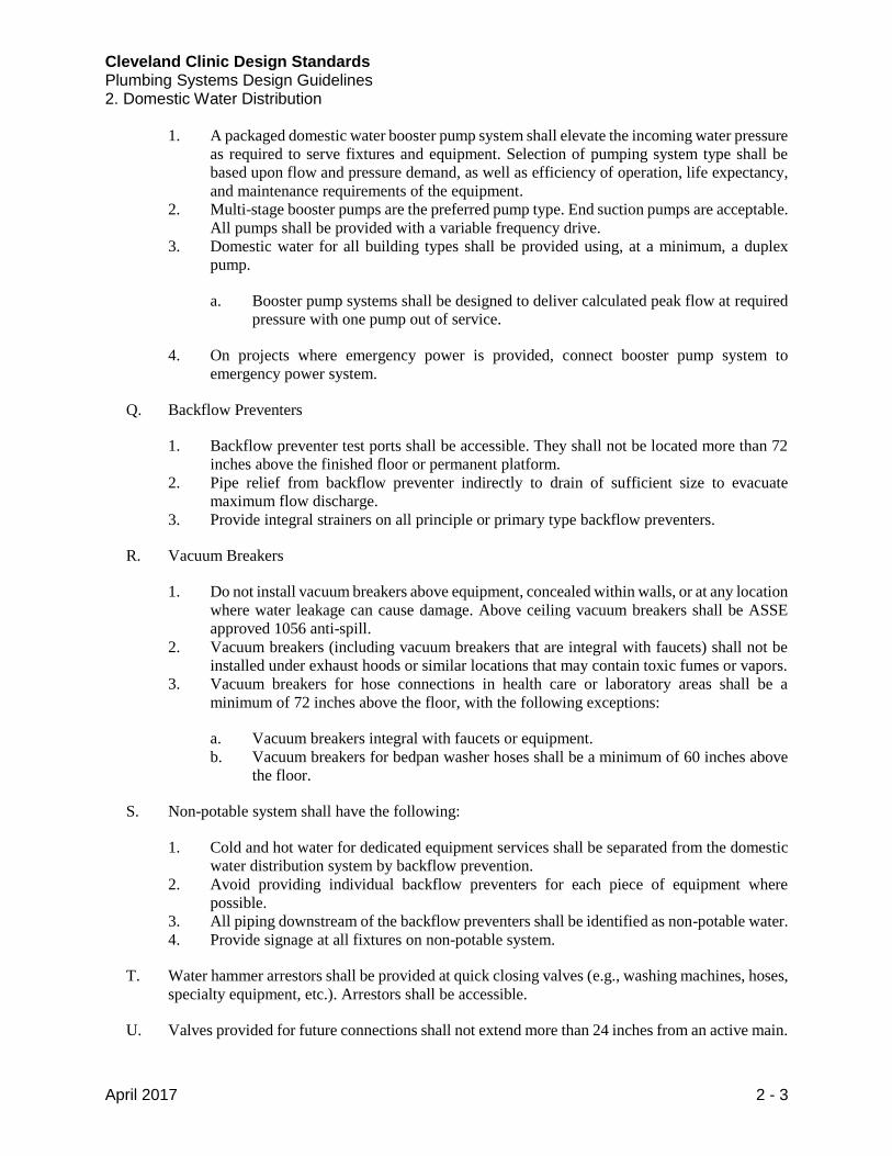
1. A packaged domestic water booster pump system shall elevate the incoming water pressure
as required to serve fixtures and equipment. Selection of pumping system type shall be
based upon flow and pressure demand, as well as efficiency of operation, life expectancy,
and maintenance requirements of the equipment.
2. Multi-stage booster pumps are the preferred pump type. End suction pumps are acceptable.
All pumps shall be provided with a variable frequency drive.
3. Domestic water for all building types shall be provided using, at a minimum, a duplex
pump.
a. Booster pump systems shall be designed to deliver calculated peak flow at required
pressure with one pump out of service.
4. On projects where emergency power is provided, connect booster pump system to
emergency power system.
Q. Backflow Preventers
1. Backflow preventer test ports shall be accessible. They shall not be located more than 72
inches above the finished floor or permanent platform.
2. Pipe relief from backflow preventer indirectly to drain of sufficient size to evacuate
maximum flow discharge.
3. Provide integral strainers on all principle or primary type backflow preventers.
R. Vacuum Breakers
1. Do not install vacuum breakers above equipment, concealed within walls, or at any location
where water leakage can cause damage. Above ceiling vacuum breakers shall be ASSE
approved 1056 anti-spill.
2. Vacuum breakers (including vacuum breakers that are integral with faucets) shall not be
installed under exhaust hoods or similar locations that may contain toxic fumes or vapors.
3. Vacuum breakers for hose connections in health care or laboratory areas shall be a
minimum of 72 inches above the floor, with the following exceptions:
a. Vacuum breakers integral with faucets or equipment.
b. Vacuum breakers for bedpan washer hoses shall be a minimum of 60 inches above
the floor.
S. Non-potable system shall have the following:
1. Cold and hot water for dedicated equipment services shall be separated from the domestic
water distribution system by backflow prevention.
2. Avoid providing individual backflow preventers for each piece of equipment where
possible.
3. All piping downstream of the backflow preventers shall be identified as non-potable water.
4. Provide signage at all fixtures on non-potable system.
T. Water hammer arrestors shall be provided at quick closing valves (e.g., washing machines, hoses,
specialty equipment, etc.). Arrestors shall be accessible.
U. Valves provided for future connections shall not extend more than 24 inches from an active main.

Cleveland Clinic Design Standards Plumbing Systems Design Guidelines 2. Domestic Water Distribution
April 2017 2 - 4
V. Where permanently disconnecting domestic water supplies serving fixtures or equipment, remove
all associated piping back to active main to avoid stagnation.
W. Coordinate utility meters and any allowable deduct meters with purveyor and sub-meters with
Cleveland Clinic.
1.2 Hospital Domestic Water Distribution Requirements
A. Building service pressure reducing valves shall have a bypass with a throttling valve.
B. Hospitals shall be provided with redundant water services to building.
1. Each service shall be provided with backflow preventer.
1.3 Ambulatory Healthcare Facility Domestic Water Distribution Requirements
A. Building service PRVs shall have a bypass with a throttling valve.
B. Building service shall be provided with redundant backflow preventers.
1.4 Outpatient Facility Domestic Water Distribution Requirements
A. Building service PRVs shall have a bypass with a throttling valve.
B. Building service shall be provided with redundant backflow preventers.
1.5 Administration Facility Domestic Water Distribution Requirements
A. Building service PRVs shall have a bypass with a throttling valve.
See the following page for Plumbing Application Schedule.

Cleveland Clinic Design Standards Plumbing Systems Design Guidelines 2. Domestic Water Distribution
April 2017 2 - 5
1.6 Plumbing Application Schedule (All Facility Types)
Pipe and Joining Application Schedule
Piped System Pipe Size
Range
Pipe Specified
Type(s)
Joining Specified
Method(s)
Domestic Water Underground
Service 2” and smaller Soft Copper “Without Joints”
Domestic Water Underground
Service 3” and larger Ductile Iron Push Joint
Domestic Water Inside Building 2” and smaller Copper Soldered or Pressed Fitting
System
Domestic Water Inside Building 2 ½” – 4” Copper
Brazed, Pressed Fitting
System, or Grooved
Joining System
Domestic Water Inside Building 5” and larger Stainless Steel (Sch.
10) or Copper Grooved Joining System
Trap Primer Feed Piping Within
Ceilings/Above Floors ½” Copper
Soldered or Pressed Fitting
System
Pipe Valve Application Schedule
Piped System Pipe Size Range Valve Type
Domestic Water (Hot and Cold) 4” and smaller Ball Valve
Domestic Water (Hot and Cold) 5” and larger Double Lug Butterfly Valve
1.7 Manufacturers
A. Refer to CC Equipment Supplier List located on Buildings and Properties Website for
acceptable equipment manufacturers. (http://portals.clevelandclinic.org/ocm)
*****

Cleveland Clinic Design Standards Plumbing Systems Design Guidelines 3. Sanitary Waste
April 2017 3 - 1
1.1 Sanitary Waste Requirements
A. Waste and vent systems shall be designed using fixture drain loads that are code compliant for
sizing and provide proper operation during periods of peak demand.
B. Where possible, main waste and vent stacks shall utilize chases or be located adjacent to columns
for vertical routing to multiple floor levels.
C. The use of double wye sanitary fittings is prohibited.
D. Laundry utility boxes shall be provided where connections to laundry equipment are required.
Provide 3-inch lateral branch pipe to the base of the box’s standpipe. Standpipe shall be 24 inches
of 2-inch pipe and a 2 inch trap.
E. Where possible, ice machine drain connections shall discharge into a hub drain with wall box. If
drain connection connects to sink, drain connection shall be above floor level/rim of sink attached.
F. Dialysis waste piping shall be acid resistant (refer to Plumbing Application Schedule, below, for
material type). Acid resistant waste piping shall be used from dialysis waste wall box to closest
sanitary stack with regularly flowing waste.
G. Trap primers shall be provided to floor drains/floor sinks that may be susceptible to trap seal
evaporation.
H. Public restrooms shall be provided with 3 inch or 4 inch floor drains.
I. The building system is anticipated to flow by gravity to the exterior municipal sanitary sewer.
Sanitary drains that cannot be discharged by gravity shall be routed to a sump and be pumped out
to a point in the sanitary system that is capable of flowing by gravity.
J. Elevator Pit Sump Pumps
1. Cast iron body submersible pumps are acceptable for elevator sumps.
2. Pump shall be provided with mechanical float.
3. Provide sump pump sized per elevator code.
4. Only metallic piping allowed within hoistway.
5. Discharge of elevator pit sump pump shall be either located outside (with splash block) or
into an open-end standpipe in a janitor’s closet. Discharge into a standard mop basin is not
acceptable.
K. Sewage Ejectors
1. Cast iron body submersible or shaft-mounted pumps are acceptable for sumps.
2. Provide duplex, lead-lag pumps. Pump’s high water alarms shall have local lights and
audible alarm in addition to being sent to building management system. High water alarm
shall be separate circuit, independent of pump circuit.
3. Locate gate and check valves outside of the pit.

Cleveland Clinic Design Standards Plumbing Systems Design Guidelines 3. Sanitary Waste
April 2017 3 - 2
L. Provide cleanouts at the base of each vertical sanitary stack and at intervals not exceeding 75 feet
in horizontal building drain. All interior cleanouts shall be accessible from walls or floors. Provide
wall cleanouts in lieu of floor cleanouts wherever possible. A floor cleanout shall be installed
only where installation of a wall cleanout is not practical. Provide a wall cleanout for each water
closet or battery of water closets. Locate wall cleanouts above the flood level rim of the highest
water closet but no more than 24 inches above the finished floor. For horizontal cleanouts, provide
an access door and blind plug. For vertical cleanouts, provide an access door, wye, and blind plug.
Plumbing Engineer is responsible for coordinating access door locations for incorporation on the
architectural plans.
M. No buried waste line shall be smaller than 3 inches. No buried vent line shall be smaller than the
full size of the sanitary pipe that it is serving. No above ground vent line shall be smaller than
1 ½ inches. No roof vent terminal shall be smaller than 3 inches. Waste piping serving water
closets shall not be smaller than 4 inches.
N. All sanitary vent terminals shall comply with local code and required minimum distances. Avoid
locating drains above sensitive equipment (e.g., MRIs, CTs, radiology imaging equipment) or
areas where water leakage would cause major property loss or contamination. Where this is
unavoidable, provide a stainless steel drain pan with drain and leak detection alarms tied into
building management system. Coordinate water tight flooring (with Architect) for rooms above
sensitive equipment.
O. Do not locate drainage or vent piping within stairways, electrical rooms, or telecommunications
rooms. Where this is unavoidable, provide a stainless steel drain pan with drain and leak detection
alarms tied into the building management system. Coordinate water tight flooring (with Architect)
for rooms above sensitive equipment.
P. Do not locate floor drains within pharmacy drug preparation areas, operating rooms, or areas
where hazardous materials are handled or stored.
See the following page for Plumbing Application Schedule.
Cleveland Clinic Design Standards Plumbing Systems Design Guidelines 3. Sanitary Waste
April 2017 3 - 3
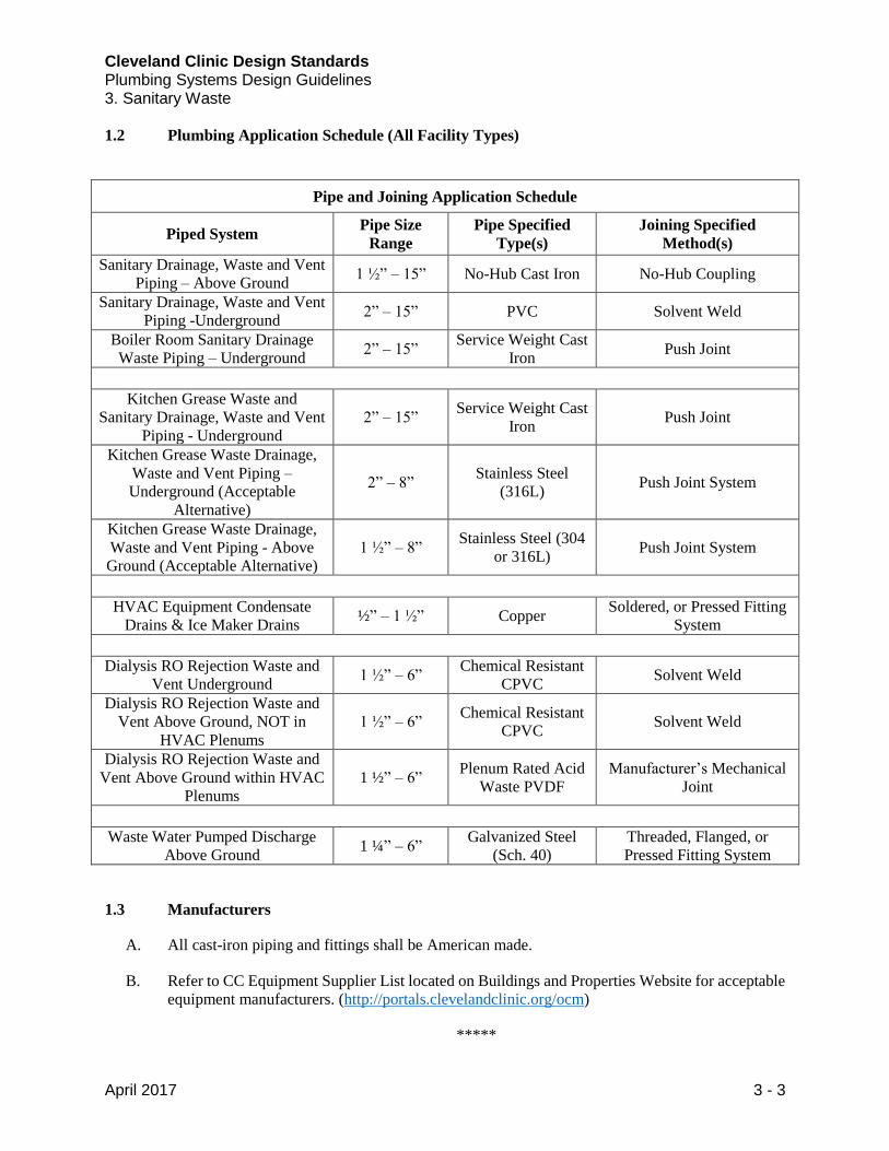
1.2 Plumbing Application Schedule (All Facility Types)
Pipe and Joining Application Schedule
Piped System Pipe Size
Range
Pipe Specified
Type(s)
Joining Specified
Method(s)
Sanitary Drainage, Waste and Vent
Piping – Above Ground 1 ½” – 15” No-Hub Cast Iron No-Hub Coupling
Sanitary Drainage, Waste and Vent
Piping -Underground 2” – 15” PVC Solvent Weld
Boiler Room Sanitary Drainage
Waste Piping – Underground 2” – 15”
Service Weight Cast
Iron Push Joint
Kitchen Grease Waste and
Sanitary Drainage, Waste and Vent
Piping - Underground
2” – 15” Service Weight Cast
Iron Push Joint
Kitchen Grease Waste Drainage,
Waste and Vent Piping –
Underground (Acceptable
Alternative)
2” – 8” Stainless Steel
(316L) Push Joint System
Kitchen Grease Waste Drainage,
Waste and Vent Piping - Above
Ground (Acceptable Alternative)
1 ½” – 8” Stainless Steel (304
or 316L) Push Joint System
HVAC Equipment Condensate
Drains & Ice Maker Drains ½” – 1 ½” Copper
Soldered, or Pressed Fitting
System
Dialysis RO Rejection Waste and
Vent Underground 1 ½” – 6”
Chemical Resistant
CPVC Solvent Weld
Dialysis RO Rejection Waste and
Vent Above Ground, NOT in
HVAC Plenums
1 ½” – 6” Chemical Resistant
CPVC Solvent Weld
Dialysis RO Rejection Waste and
Vent Above Ground within HVAC
Plenums
1 ½” – 6” Plenum Rated Acid
Waste PVDF
Manufacturer’s Mechanical
Joint
Waste Water Pumped Discharge
Above Ground 1 ¼” – 6”
Galvanized Steel
(Sch. 40)
Threaded, Flanged, or
Pressed Fitting System
1.3 Manufacturers
A. All cast-iron piping and fittings shall be American made.
B. Refer to CC Equipment Supplier List located on Buildings and Properties Website for acceptable
equipment manufacturers. (http://portals.clevelandclinic.org/ocm)
*****

Cleveland Clinic Design Standards Plumbing Systems Design Guidelines 4. Storm Drainage
April 2017 4 - 1
1.1 Facility Storm Drainage Requirements
A. Primary and secondary roof drain systems shall be designed using the applicable rainfall rate in
conjunction with code established areas-to-pipe sizes allowed.
B. Storm water drainage systems shall be provided to convey rainwater from roof and area drains to
the site municipal storm sewer system. Secondary emergency overflow systems shall be installed
to protect parapeted roof structures in the event of primary system blockage.
C. Avoid locating sumps or piping above sensitive equipment (e.g., MRIs, CTs, radiology imaging
equipment) or areas where water leakage would cause major property loss or contamination.
Where this is unavoidable, provide a stainless steel drain pan with drain and leak detection alarms
tied into the building management system. Coordinate water tight flooring (with Architect) for
rooms above sensitive equipment.
D. Do not locate drain sumps or piping within stairways, electrical rooms, or telecommunications
rooms. Where this is unavoidable, provide a stainless steel drain pan with drain and leak detection
alarms tied into the building management system. Coordinate water tight flooring (with Architect)
for rooms above sensitive equipment.
E. No roof drain shall have an outlet connection smaller than 3 inches.
F. Storm drains that cannot be discharged by gravity shall be routed to a sump and be pumped out
to a point in the storm system that is capable of flowing by gravity.
G. Sump Pumps
1. Cast iron body submersible or shaft-mounted pumps are acceptable for sumps.
2. Pump shall be provided with a mechanical float.
3. Provide duplex, lead-lag pumps in sump pits where there is predicted constant water flow.
Pump’s high water alarms shall have local lights and audible alarm in addition to being
sent to building management system. High water alarm shall be on separate circuit,
independent of pump circuit.
4. Locate gate and check valves outside the pit.
H. Provide cleanouts at the base of each vertical downspout and at intervals not exceeding 75 feet in
horizontal building drain. All interior cleanouts shall be accessible from walls or floors. For
horizontal cleanouts, provide an access door and blind plug. For vertical cleanouts, provide an
access door, wye, and blind plug. Plumbing Engineer is responsible for coordinating access door
locations for incorporation on the architectural plans.

Cleveland Clinic Design Standards Plumbing Systems Design Guidelines 4. Storm Drainage
April 2017 4 - 2
1.2 Plumbing Application Schedule (All Facility Types)
Pipe and Joining Application Schedule
Piped System Pipe Size
Range Pipe Specified Type(s)
Joining Specified
Method(s)
Storm Drainage Piping, Underground 3” – 15” Service Weight Cast
Iron Push Joint
Storm Drainage Piping, Underground 3” – 15” PVC Solvent Weld
Storm Drainage Piping, Above Ground 3” – 15” No-hub Cast Iron No-Hub Coupling
1.3 Manufacturers
A. All cast-iron piping and fittings shall be American made.
B. Refer to CC Equipment Supplier List located on Buildings and Properties Website for acceptable
equipment manufacturers. (http://portals.clevelandclinic.org/ocm)
*****

Cleveland Clinic Design Standards Plumbing Systems Design Guidelines 5. Domestic Water Heating Equipment
April 2017 5 - 1
1.1 Domestic Water Heating Equipment Requirements
A. Where steam boilers are provided or centralized steam is available, utilize semi-instantaneous
type with steam to hot-water or hot-water to hot-water double wall heat exchangers. Natural gas
fired heaters may be provided where natural gas service is readily available and when considered
applicable by the Design Team and approved by Cleveland Clinic. Condensing domestic water
heaters are acceptable.
B. Kitchens may be served from building hot water system, but shall have a dedicated branch line
tied into the building hot water system upstream of central thermostatic mixing valve.
1. Provide alternate hot water temperatures (as required) for food service and dishwasher
equipment. Discharge water temperature from service equipment shall be cooled in
accordance with local code requirements prior to entering sanitary system.
C. Hot water heating equipment serving areas other than food service may be generated by
centralized heaters or point-of-use heaters. All hot water shall be generated to 140° F and mixed
to 122°F – 123°F before distribution. Return hot water temperature shall be 115°F – 116°F.
1. Reduce temperature at plumbing fixture outlet as required by local code.
2. Sterilization water that is not exposed to general staff shall be 160°F.
3. Separate water heating equipment and circulation pumps shall be provided for each
pressure zone within a high-rise building. All high-rise plumbing distribution designs shall
be reviewed with CC Engineer during schematic design of project.
D. Provide pre-pressurized steel thermal expansion tank with membrane on the cold water supply
line of all water heating equipment where cold water service contains check valves, pressure
reducing valves, or backflow preventers. Thermal expansion tanks shall meet all pressure vessel
standards applicable to the connected hot water system.
1.2 Hospital Domestic Water Heater Requirements
A. Domestic water heating equipment shall include 20% extra capacity for future renovations.
B. The building shall be supplied with a fully redundant domestic water system (N+1), including
heat exchangers/heaters and recirculating pumps.
1. Natural gas fired domestic water heaters shall be capable of dual fuel operation.
Cleveland Clinic Design Standards Plumbing Systems Design Guidelines 5. Domestic Water Heating Equipment
April 2017 5 - 2
1.3 Ambulatory Healthcare Facility Domestic Water Heater Requirements
A. Domestic water heating equipment shall include 10 – 15% extra capacity for future renovations.
Extra capacity shall be reviewed with CC Engineer during project design.
B. Dual fuel requirement shall be determined based on facility’s emergency operational plan.
1. If dual fuel is required, domestic heat exchanger/heater requirements shall match those
listed in Hospital Requirements.
2. If dual fuel is not required, domestic water shall be produced using high efficiency
domestic water heaters.
a. Condensing style domestic water heaters shall be considered for increased
efficiency, but system shall be designed for optimum efficiency.
1.4 Outpatient Facility Domestic Water Heater Requirements
A. Domestic water heating equipment shall include 10% extra capacity for future renovations. Extra
capacity shall be reviewed with CC Engineer during project design.
B. Dual fuel will not typically be required, but shall be reviewed with CC Engineer during project
design.
C. Condensing style domestic water heaters shall be considered for increased efficiency, but return
shall be designed for optimum efficiency.
1.5 Administration Facility Domestic Water Heater Requirements
A. Review domestic water heating equipment requirements with CC Engineer during project design.
B. Condensing style domestic water heaters shall be considered for increased efficiency, but system
shall be designed for optimum efficiency.
1.6 Manufacturers
A. Refer to CC Equipment Supplier List located on Buildings and Properties Website for acceptable
equipment manufacturers. (http://portals.clevelandclinic.org/ocm)
*****

Cleveland Clinic Design Standards Plumbing Systems Design Guidelines 6. Plumbing Fixtures
April 2017 6 - 1
1.1 Plumbing Fixture Requirements
A. Fixtures and trim specified for renovation of existing facilities shall match existing installation
where possible.
B. Fixtures, trim, and accessories shall be institutional/commercial grade quality.
C. Vitreous china plumbing fixtures shall be white or bone in color with chrome-plated brass fixture
trim and accessories.
D. Wall mounted fixtures shall be supported with commercial carriers, bolted to the floor.
1. Wall hung water closets installations shall be capable to withstand a minimum of 500 lbs.
Provide vitreous china fixtures compliant to ASME A11.2.19.2.2M 500 lb. load test, and
install using a heavy duty 500 lb. rated carrier. Standard 300 lb. rated carriers are not
acceptable.
a. All carriers shall be installed and anchored in accordance with the manufacturer’s
published instructions.
E. Bariatric fixtures and associated carriers shall be reviewed with CC Engineer during design.
F. Fixtures exposed to the public shall be provided with vandal resistant trim.
G. Electric water coolers shall be recessed in wall and provided with bottle filling station.
H. Water flows indicated in guideline are Cleveland Clinic standard flow rates. Low flow rates may
be required based on project requirements (LEED, etc.). Any deviation from standard flow rates
shall be reviewed with CC Engineer.
1.2 Electronic Sensor Activated Fixture Trim
A. Where electronic sensor faucets and flush valves are required, sensors shall be battery powered.
Batteries shall have a three (3) year minimum life expectancy.
B. All electronic flush valve sensors shall be provided with a manual override button except when
located within specimen collecting toilet rooms.
1.3 Sinks
A. General
1. Stainless steel sinks shall be 18 gauge Type 304 stainless steel with insulation
undercoating.
2. Fixture trim and accessories shall be chrome-plated.
3. All faucets shall be provided with ceramic disc cartridges.

Cleveland Clinic Design Standards Plumbing Systems Design Guidelines 6. Plumbing Fixtures
April 2017 6 - 2
4. All sinks primarily used for hand washing shall be provided with grid strainer drain with
5/16-inch holes. Drain stoppers or crumb-cup strainers shall only be used for break rooms.
B. Patient Room
1. Sink style shall be coordinated with CC Architectural Standards and project requirements.
2. Faucet
a. Manual operation with 4 inch minimum wrist blade handles
b. Gooseneck spout (with outlet a minimum of 5 inches above floor level rim of fixture)
c. Laminar flow outlet. Standard flow shall be 1.0 GPM, but reduced flow outlets are
acceptable. Hot water delivery time shall be considered if reduced flow outlet is
used.
C. Medical Staff General Use
1. Sink style shall be coordinated with CC Architectural Standards and project requirements.
2. Faucet
a. Manual operation with 4 inch minimum wrist blade handles.
1) Electronic sensor faucet is acceptable.
b. Gooseneck spout (with outlet a minimum of 5 inches above floor level rim of fixture)
c. Laminar flow outlet. Standard flow shall be 1.0 GPM, but reduced flow outlets are
acceptable. Hot water delivery time shall be considered if reduced flow outlet is
used.
D. Surgery Scrub Sink
1. Provide with electronic sensor controls.
E. Lab
1. Lab sinks used for general research shall be provided with manually operated faucets
served with cold water only. If hot water is required, a separate non-potable hot water
system shall be provided.
a. Sink shall be labeled as non-potable.
2. Sinks located in BSL-2 or higher tissue culture rooms shall be provided with foot pedal or
electronic sensor activated faucets with programmable run time.
1.4 Lavatories
A. General
1. Fixture trim and accessories shall be chrome-plated.
2. All faucets shall be provided with ceramic disc cartridges.

Cleveland Clinic Design Standards Plumbing Systems Design Guidelines 6. Plumbing Fixtures
April 2017 6 - 3
3. Lavatories shall be provided with grid strainer drain with 5/16-inch holes. Drain stoppers
or mechanical (pop-up) waste fittings will not be acceptable.
B. Public Bathroom
1. Lavatory style shall be coordinated with CC Architectural Standards and project
requirements.
2. Electronic sensor faucet (0.5 GPM)
C. Staff Bathroom
1. Lavatory style shall be coordinated with CC Architectural Standards and project
requirements.
2. Electronic sensor faucet (1.0 GPM)
D. Patient Room
1. Lavatory style shall be coordinated with CC Architectural Standards and project
requirements.
2. Faucet
a. Manual operation with 4 inch minimum wrist blade handles
b. Gooseneck spout (with outlet a minimum of 5 inches above floor level rim of fixture)
c. Laminar flow outlet. Standard flow shall be 1.0 GPM, but reduced flow outlets are
acceptable. Hot water delivery time shall be considered if reduced flow outlet is
used.
3. Lavatory faucets located in specimen collecting toilet rooms shall be provided with AC
powered electronic sensors. The electrical power shall be controlled by a wall switch
located outside of the toilet room to allow nursing staff to prevent use of faucet during
collection of specimen. Coordinate with Cleveland Clinic staff for exact location of wall
switch.
1.5 Mop Basins
A. Mop basin faucets in housekeeping closets shall be provided with automatic return stems that
require the handle to be manually held open for water to flow.
B. Provide accessible pipeline check valves on hot and cold piping to all housekeeping/service sink
faucets or mixing hose bibs. Housekeeping/service sink faucets shall be provided with vacuum
breaker.
1.6 Clinic Sinks
A. When possible, bedpan cleansing shall occur in patient room toilet. Where not applicable (e.g.,
ICU, PACU, ED, etc.), bedpan cleansing shall occur in soiled utility room. In soiled utility rooms
where bedpan cleansing will occur, clinic sinks shall be provided with the following accessories:

Cleveland Clinic Design Standards Plumbing Systems Design Guidelines 6. Plumbing Fixtures
April 2017 6 - 4
1. Wall mounted china is preferred. Floor mounted with terrazzo floor base is acceptable.
2. Flush valve (6.5 gallon flush)
3. Foot pedal operated, hand-held hose spray bed pan washer
4. Service sink faucet with 6 inch wrist blade handles
B. Locations and accessories of all clinic sinks shall be reviewed with CC Engineer during design.
1.7 Water Closets
A. General Design
1. Toilets shall be wall mounted vitreous china with elongated bowl, siphon jet flushing
action, and 1 ½ inch top inlet spud.
2. Flush valves shall be chrome-plated brass, exposed type.
3. Seats shall have open front and stainless steel self-sustaining check hinges.
4. Refer to wall carrier requirements in Section 1.1 Plumbing Fixture Requirements.
B. Patient Bathroom
1. Water closets shall be mounted at ADA height, expect in pediatric areas.
2. Water closets shall be provided with integral bedpan lugs.
3. Flush valves shall be manually operated (1.6 gallon flush).
a. Coordinate requirements for fold-down bedpan washer on a per project basis for
patient room toilets. Flush valve height shall be coordinated with grab bar locations
to avoid interference. Offset flush valves for bedpan washers are typically required
to avoid grab bar interference.
4. Flush valves located in specimen collecting toilet rooms shall be provided with AC
powered electronic sensors. The electrical power shall be controlled by a wall switch
located outside of the toilet room to allow nursing staff to prevent use of faucet during
collection of specimen. Coordinate with Cleveland Clinic staff for exact location of wall
switch.
C. Public and Staff Bathroom
1. Flush valves shall be electronic sensor operated (1.6 gallon flush).
1.8 Urinals
A. Urinals shall be wall mounted with carrier, vitreous china with elongated rim (14 inch minimum),
washout flushing action, and ¾ inch top inlet spud.
B. Waterless urinals are prohibited.
C. Urinal flush valves shall be 0.5 GPM, electronic sensor operated, chrome plated brass exposed
type.

Cleveland Clinic Design Standards Plumbing Systems Design Guidelines 6. Plumbing Fixtures
April 2017 6 - 5
1.9 Showers And Bathtubs
A. Shower and bathtub mixing valves shall be combination thermostatic and pressure-balancing type
with water temperature limit stops set at 110°F. Mixing valves shall have integral check stops
accessible for servicing.
B. Shower heads shall have a flow of 1.5 GPM.
C. Shower finished floor and bathtub bottom shall be slip resistant.
D. Bathtubs shall be enameled cast iron or high strength composite material with porcelain finish.
Enameled steel bathtubs are not acceptable.
1.10 Emergency Showers and Eyewashes
A. Emergency shower and eyewash equipment design, installation, and location shall meet current
ANSI Z358.1, NFPA 99-11.6 and OSHA 29 CFR 1910.151 standards and deliver clean water to
users. All locations shall be reviewed with CC Engineer and Environmental Health and Safety
department.
B. Coordinate location of safety drenching equipment on upper levels with spaces below to avoid
areas where water leakage would cause major property loss or contamination, including but not
limited to computer data centers, MRI rooms, electrical rooms, telecommunications rooms, food
preparation, food storage, food serving, critical patient care areas, etc.
C. A handheld drench hose or personal eyewash station may be installed in laboratory or shop areas
as a supplement, not a substitute, for eyewash devices.
D. Emergency eye wash and shower equipment shall be provided with mixing valves that are factory
set to deliver tepid water outlet flow (60°F – 100°F).
E. Safety drenching equipment shall be identified with a highly visible sign, and area lighting shall
be adequate to facilitate use.
F. Provide an accessible ball type shutoff valve and check valves in individual water supply line
serving safety drenching equipment. Valves shall be labeled for identification and locked in the
open position.
G. Floor drains/floor sinks are required for emergency showers.
H. Provide emergency eye wash station adjacent to chemical treatment areas in mechanical rooms.
1.11 Manufacturers
A. Refer to CC Equipment Supplier List located on Buildings and Properties Website for acceptable
equipment manufacturers. (http://portals.clevelandclinic.org/ocm)
*****

Cleveland Clinic Design Standards Plumbing Systems Design Guidelines 7. Plumbing Insulation and Labeling
April 2017 7 - 1
1.1 Plumbing Insulation Requirements
A. General Design
1. All insulation shall have a system fire and smoke hazard rating as tested by procedure
ASTM-E-84, NFPA 255, and UL 723 not exceeding Flame Spread 25 and Smoke
Developed 50. The system rating shall be based on insulation, jacket, adhesives, coatings,
fittings, and cements. Any treatment of jackets or facings to impede flame and/or smoke
shall be permanent. The use of water-soluble treatments is prohibited.
B. Piping Insulation
1. All piping shall be insulated per the latest edition of ASHRAE 90.1.
2. The maximum temperature limit of the insulation must be above the maximum operating
temperature of piping. Surface temperature of insulation for heated piping in still ambient
air at 80°F shall not be above 110°F at the pipe operating temperature below 400°F.
3. Thickness of insulation for cold piping shall be selected to prevent condensation on the
surface of insulation with ambient temperature is 50°F above the pipe temperature. Specify
that insulation be installed with a continuous unbroken and un-punctured factory applied
vapor barrier.
4. Fittings, flanges, unions, and valves shall be insulated. Insulation shall be beveled down to
unions with all exposed ends sealed. Insulation covers shall be either prefabricated or
fabricated of pipe insulation. Insulation efficiency shall not be less than that of the
adjoining piping.
5. Hangers, supports, and anchors secured directly to cold surfaces must be adequately
insulated and vapor sealed to prevent condensation.
1.2 Plumbing Application Schedule (All Facility Types)
Piping Insulation Application Schedule
Piped System Minimum Insulation
Thickness Insulation Type
Domestic Cold Water Per ASHRAE 90.1 Fiberglass Insulation
Domestic Hot Water Per ASHRAE 90.1 Fiberglass Insulation
Domestic Recirculating Water Per ASHRAE 90.1 Fiberglass Insulation
Horizontal Storm Conductors 1” Fiberglass Insulation
Sanitary Piping carrying A/C
condensate drainage from drain
body to sanitary riser
1” Closed-Cell Insulation
1. All piping labels shall have direction of flow indicated.
2. Review non-potable water labeling requirements with CC Engineer during design.

Cleveland Clinic Design Standards Plumbing Systems Design Guidelines 7. Plumbing Insulation and Labeling
April 2017 7 - 2
Labeling Schedule
System Label Description Label Type/Material
Compressed Air COMPRESSED AIR Snap-Around Label
Acid Vent ACID VENT Snap-Around Label
Acid Waste ACID WASTE Snap-Around Label
Carbon Dioxide CARBON DIOXIDE Snap-Around Label
Deionized Water DEIONIZED WATER Snap-Around Label
Domestic Cold Water DOMESTIC COLD WATER Snap-Around Label
Domestic Hot Water DOMESTIC HOT WATER Snap-Around Label
Domestic Recirculating Hot Water DOMESTIC RECIRCULATING
HOT WATER Snap-Around Label
Natural Gas NATURAL GAS Snap-Around Label
Medical Air MEDICAL AIR Snap-Around Label
Medical Air Intake MEDICAL AIR INTAKE Snap-Around Label
Medical Vacuum MEDICAL VACUUM Snap-Around Label
Medical Vacuum Discharge MEDICAL VACUUM
DISCHARGE Snap-Around Label
Nitrogen Piping NITROGEN Snap-Around Label
Nitrous Oxide NITROUS OXIDE Snap-Around Label
Non-Potable Cold Water NON-POTABLE COLD WATER Snap-Around Label
Non-Potable Hot Water NON-POTABLE HOT WATER Snap-Around Label
Non-Potable Recirculating Hot
Water
NON-POTABLE
RECIRCULATING HOT WATER Snap-Around Label
Oxygen OXYGEN Snap-Around Label
Overflow Storm Drainage OVERFLOW STORM Snap-Around Label
Process Air PROCESS AIR Snap-Around Label
Purified Water PURIFIFED WATER Snap-Around Label
Sanitary Drainage SANITARY Snap-Around Label
Storm Drainage STORM Snap-Around Label
Tempered Hot Water TEMPERED HOT WATER Snap-Around Label
Vent VENT Snap-Around Label
Waste Anesthetic Gas Disposal WAGD Snap-Around Label
140°F Hot Water Piping 140°F HOT WATER Snap-Around Label
140°F Recirculating Hot Water
Piping
140°F RECIRCULATING HOT
WATER Snap-Around Label
1.3 Manufacturers
A. Refer to CC Equipment Supplier List located on Buildings and Properties Website for acceptable
equipment manufacturers. (http://portals.clevelandclinic.org/ocm)
*****
Cleveland Clinic Design Standards Plumbing Systems Design Guidelines 8. Gas and Vacuum Systems
April 2017 8 - 1
1.1 Hospital Gas and Vacuum Systems Requirements
A. Vacuum and gas systems shall be designed in accordance with current editions of FGI Guidelines
for Design and Construction of Hospitals and Healthcare Facilities, NFPA 55, NFPA 99,
Compressed Gas Association Standards, and ASSE 6000.
B. Review the location, quantity, and type of gas outlets, inlets, and alarm panels with Cleveland
Clinic gas commissioning consultant during the design development phase of the project.
C. Medical vacuum and gas systems serving patients shall be independent of all other vacuum and
gas systems serving laboratory, research, and/or animal areas.
D. Medical and laboratory compressed air systems serving patients or labs shall not be used to serve
non-respiratory equipment such as sterilizers, pneumatic doors, operating room service columns,
etc.
E. Design medical gas and vacuum systems to deliver nominal pressures in accordance with NFPA
99. If an existing facility operates at different pressures, coordinate all pressures with existing
facility and medical gas verifier.
F. Coordinate the requirement for the use of ventilators with Cleveland Clinic user groups. Design
the oxygen and medical air systems to accommodate required flow demands.
G. Include waste anesthetic gas disposal (WAGD) terminal inlets and piping where appropriate. The
source for WAGD inlets shall be an independent system from the medical vacuum system.
H. Provide at least one instrument air/nitrogen control panel (ICP) within rooms containing
instrument air outlets used for equipment. Verify need for instrument air / nitrogen / electric for
surgical tools with Cleveland Clinic on each project.
I. For surgical boom brakes within hospitals that require a pressure reducing valve on incoming gas,
provide redundant pressure reducing valves for manual switch-over located outside operating
room in accessible ceiling.
J. Locate station inlets and outlets at an appropriate height to prevent physical damage to attached
equipment and accessories. Station inlets and outlets located above countertops shall be provided
with sufficient space to allow usage and attachment of equipment without interferences by
countertop, backsplash, or overhead cabinets. All other station inlets and outlets having centerline
located less than 60 inches above finished floor shall be protected by guardrails, recessing into
walls, or by other means approved by Cleveland Clinic. Outlets shall be free and clear for testing.
K. Provide sufficient spacing between station inlets and outlets to allow simultaneous use with
vacuum collection bottles, regulators, adaptors, or any other equipment attached. Provide slide
retainer bracket for collection bottle attachment adjacent to each vacuum station inlet.
Renovations shall be updated so that they are installed the same as installing new.
L. Oxygen outlets for Series B type shall be provided with integral “hook plate” outlet cover.

Cleveland Clinic Design Standards Plumbing Systems Design Guidelines 8. Gas and Vacuum Systems
April 2017 8 - 2
M. Ensure that all vacuum and gas source equipment and alarm systems are provided with both
normal and emergency electrical power supply.
N. Drawings shall indicate all valves and pressure sensor locations.
O. All sourcing equipment shall be able to report to the master alarm panel.
P. Central Supply Systems
1. Locate air compressors and vacuum pumps in a dedicated mechanical room in accordance
with NFPA 99. Mechanical room shall provide a clean, relatively cool environment (i.e.,
not to exceed 100°F ambient temperature). Equipment shall be located with adequate
access space for regular monitoring and servicing. Provide floor drain adjacent to
equipment pads. Floor drains serving vacuum pumps shall be provided with smooth, acid
resistant interior coating. Provide a hose bib within mechanical room.
2. Terminate vacuum exhaust discharge outdoors above roof level, at least 25 feet
horizontally (may be more depending upon prevailing wind direction and velocity) from
all air intakes, doors, windows, louvers, or any other building openings. Combine exhaust
from each vacuum pump into one discharge pipe, sized for no restriction while flowing
maximum discharge possible, and provide with an isolation valve at the header for each
pump served. Avoid traps, but where installed provide low point drains. Exhaust piping for
vacuum pumps shall be sized using the total SCFM for the system (both lead and lag
pumps) and the total developed length of run. Exhaust piping shall be sized and arranged
to prevent moisture and back-pressure from entering pump. Provide valved drip-leg at base
of exhaust stacks. Coordinate with vacuum pump system technical representative and
verify that proposed sizing of exhaust piping complies with manufacturer’s
recommendations.
3. Air compressors and vacuum pumps shall be multiplexed with receiver tanks and sized
such that 100% of the design load is carried when the largest single is unit out of service.
Increase the calculated (SCFM) load by 20% to accommodate future system expansion.
4. In designing a medical air system where ventilators are expected to be utilized, add the
ventilator requirement for each ventilator in use to the compressor sizing.
5. Design air dryers, filters, and pressure regulators for the air system in triplex, each sized
for 100% of the load using duplex twin tower desiccant dryers. Include continuous line
dew point and carbon monoxide monitoring with sample connections on the discharge
piping downstream of the filters and regulators. Locate monitors at, or integral with, the
control panel.
6. Rooms for gas cylinder storage and manifolded systems shall be sized, ventilated, and
constructed in accordance with NFPA 99. Coordinate with Cleveland Clinic to determine
space required for storage of additional non-manifolded cylinders. Gas cylinder storage
rooms shall be located at a readily accessible location and provided with a minimum 42
inch door. Allow for 25% expansion.
7. Provide local user alarms for cylinder manifolds.
8. Bulk liquid oxygen supply systems shall be designed and located in accordance with NFPA
55 and closely coordinated with Cleveland Clinic and designated oxygen supplier. Provide
emergency oxygen inlet on exterior wall of building served. Insure that location of inlet
allows truck access and that concrete pavement is provided where truck will park during
transfer of oxygen. Provide with user alarm wiring to report to alarm system.
Q. Alarm Systems

Cleveland Clinic Design Standards Plumbing Systems Design Guidelines 8. Gas and Vacuum Systems
April 2017 8 - 3
1. To ensure continuous responsible observation, provide two master system alarms, in
separate warning locations, monitored 24/7, for all vacuum and gas source equipment
systems. Coordinate both master alarm panel locations with the user facility and the other
design services. When selecting alarm locations, consider emergency power circuits,
engineering control center data relay interface locations, and the facility’s established
procedures for monitoring alarm signals. The master alarm shall have extra wires for future
capacity to be coordinated with Cleveland Clinic engineering. Extend master alarm wiring
in separate conduits for redundancy.
a. The primary warning location shall be located to assure 24-hour constant
surveillance, such as in a security office or other continuously staffed location. The
secondary warning location shall be supervised by engineering personnel and is
required to be located at one of the following (in order of priority): Boiler plant
control office, engineering control center, or in the office or principal working area
of the individual responsible for the maintenance of the vacuum and gas systems.
2. Provide local area alarms for all branches serving medical vacuum and gas station outlets
and inlets. Locate area alarms at nurse stations visible and accessible to staff for
monitoring.
a. Provide alarm sensors in zone valve boxes.
1) For anesthetizing and critical care locations, review all alarm sensor locations
with CC Engineer.
3. Provide high/low line pressure/vacuum sensors at most remote points from source
equipment in each system. Status of remote monitoring points shall be annunciated at both
master system alarm locations.
R. Piping Systems
1. Design pressure piping systems, except nitrogen, not to exceed 35 kPa (5 PSI) loss from
source to point of use. Design nitrogen piping systems not to exceed 138 kPa (20 PSI) loss
from source to point of use. Design vacuum piping systems not to exceed 10 kPa (3 inches
Hg) from source to point of use.
2. Include ventilator demand in sizing calculations for oxygen and compressed air piping.
Ventilator usage shall be based upon full flow with no diversity for each ventilator from
the outlet back to the source.
3. Bulk oxygen vaporizers shall be based on full flow with no diversity.
4. Design medical gas and vacuum piping systems based upon the following minimum flow
rates for any pipe section.
Gas Minimum Flow Rate
Oxygen 200 L/min (7 SCFM)
Medical Air 200 L/min (7 SCFM)
Vacuum 85 L/min (3 SCFM)
Nitrous Oxide 28 L/min (1 SCFM)
Carbon Dioxide 28 L/min (1 SCFM)
Nitrogen 425 L/min (15 SCFM)

Cleveland Clinic Design Standards Plumbing Systems Design Guidelines 8. Gas and Vacuum Systems
April 2017 8 - 4
5. Include a 25% calculated (SCFM) load for sizing distribution mains to accommodate future
system expansion.
6. Distribution piping shall be designed in accordance with the following minimum size
parameters to allow for future expansion and minimize service interruptions during
renovations.
a. Pressure Gases
1) Branch lines and drops to individual outlets for the pressure gases shall be a
minimum of ½ inch.
2) Branch lines serving zone valve or more than one room shall be a minimum
of ¾ inch.
b. Vacuum
1) Branch lines and drops to individual vacuum inlets shall be a minimum of ¾
inch.
2) Branch lines serving a zone valve or more than one room shall be a minimum
of 1 inch.
7. Design carbon dioxide distribution piping for total load, no diversity.
S. Renovation Projects
1. Survey current installation and coordinate with CC Engineer to verify type, location, size,
and capacities of existing piping and source equipment for determining adequate tie-in
points.
2. Survey current installation to ascertain the type of existing alarms, gas station outlets, and
vacuum terminal inlets. All new alarms shall match and be compatible with the existing
installation. All new outlets and inlets shall match the existing terminal connections and
not require the use of secondary adapters. In cases where existing alarms, station outlets,
or terminal inlets are no longer available, not U.L. approved, or are not NFPA 99 compliant,
the Design Team shall coordinate with CC Engineer to determine types to be specified
within Contract Documents. Outlets shall be DISS or quick connect, BeaconMedaes style.
3. Review the proposed alarm, outlet and inlet types, and connection locations to existing
piping and alarms with CC Engineer during the design development phase of the project.
4. Provide a shut-off valve at the connection of new line to existing line.
1.2 Laboratory Gas and Vacuum System Requirements
A. Laboratory gas and vacuum systems shall match requirements listed in 1.1 Hospital Gas and
Vacuum, except where indicated in this section.
B. Laboratory gases for vivarium labs shall be hospital grade quality.
C. Master alarm panels are not required for laboratories. Provide area alarm panels for local
alarming.

Cleveland Clinic Design Standards Plumbing Systems Design Guidelines 8. Gas and Vacuum Systems
April 2017 8 - 5
1.3 Ambulatory Healthcare Facility Gas and Vacuum System Requirements
A. Shall follow all hospital requirements.
1.4 Outpatient Healthcare Facility Gas and Vacuum System Requirements
A. Shall follow all hospital requirements, with the following exception:
1. Medical air compressors and vacuum pumps shall be duplex.
1.5 Installation and Verification Requirements:
A. Medical gas installers shall be ASSE 6010 certified.
B. Medical gas verifiers shall be ASSE 6030 certified.
1. Installation reports shall integrate into existing facility’s database software.
1.6 Manufacturers
A. Refer to CC Equipment Supplier List located on Buildings and Properties Website for acceptable
equipment manufacturers. (http://portals.clevelandclinic.org/ocm)
*****

Cleveland Clinic Design Standards Plumbing Systems Design Guidelines 9. Facility Natural Gas Piping
April 2017 9 - 1
1.1 Natural Gas Distribution Requirements
A. All natural gas piping on the customer side of the utility meter shall be designed, installed and
tested in accordance with NFPA 54 and International Fuel Gas Code (most current edition).
B. Building natural gas distribution shall be metered and valved in accordance with the gas supplier’s
requirements.
C. Building supply and distribution systems design shall provide a volume of gas at the required
flows and pressures to ensure safe, efficient, and code-compliant operation during periods of peak
demand. Piping shall be sized in accordance with referenced codes and standards.
D. Natural gas pressures shall not exceed 5 PSIG on customer side of the meter, for non-utility
buildings.
E. Provide readily accessible manual shut-off valve outside of building at service entrance.
F. Avoid locating gas piping within confined or unventilated spaces where leaking gas might collect.
G. Do not locate gas piping within stairways, electrical rooms, or telecommunications rooms.
H. Exposed and accessible shut-off valves shall be provided for proper operation and servicing of
system. Valves located above ceilings shall not be located in concealed areas or shall be provided
with access panels in hard ceilings. Locations shall include, but not be limited to, the following:
at the base of each riser, at each branch connection to risers, at each piece of equipment, where
recommended by equipment manufacturer, and at strategic locations to allow sectional isolation
while limiting disruption of services to large portions of the system. Provide pressure gauges on
each side of the valve. Provide valve on riser to each pressure gauge.
I. Valves, regulators, flanges, unions, and similar appurtenances shall be accessible for operation
and servicing. They are not be located above ceilings, within partitions, or in spaces utilized as
return air plenums.
J. Natural gas piping, including service drops, shall be no smaller than ¾ inches inside diameter.
Exception: Local connections to individual equipment and outlets may be smaller than ¾ inches
as required for that particular component. Transition and valve within 12 inches of connection.
K. Provide a manual shut-off valve in each line serving individual laboratory rooms for maintenance
and isolation of natural gas serving each room. Room manual isolation valves shall be labeled to
indicate the room being controlled and located to be accessible to maintenance staff.
L. Within each laboratory, and adjacent to room exit, provide an emergency shut-off valve. Locate
the valve exposed on wall, 54 inches above finished floor.
M. Butterfly valves are not acceptable.

Cleveland Clinic Design Standards Plumbing Systems Design Guidelines 9. Facility Natural Gas Piping
April 2017 9 - 2
1.2 Natural Gas Application Schedule
Pipe and Joining Application Schedule
Piped System Pipe Size
Range
Pipe Specified
Type(s) Joining Specified Method(s)
Natural Gas Inside Building or Outside
Building (Above Ground and Accessible)
2” and
smaller Black Steel (Sch. 40) Threaded
Natural Gas Inside Building or Outside
Building (Above Ground)
2 ½” and
larger Black Steel (Sch. 40) Welded
1.3 Manufacturers
A. Refer to CC Equipment Supplier List located on Buildings and Properties Website for acceptable
equipment manufacturers. (http://portals.clevelandclinic.org/ocm)
*****
Cleveland Clinic Design Standards Plumbing Systems Design Guidelines 10. Laboratory Water and Waste Systems
April 2017 10 - 1
1.1 Laboratory Water Systems Requirements
A. Laboratory reverse osmosis (RO) water system shall be provided for analysis equipment and
testing locations within the laboratory.
B. A dedicated laboratory cold water and hot water system shall be provided for laboratory use at
dirty sinks and where back siphonage can occur. These systems shall be separated from the normal
domestic cold and hot water system using duplex reduced pressure backflow preventer.
C. Building domestic cold and hot water shall be used for remaining clean sink locations and for
safety shower/eyewash tempering valves.
D. Central tempering valves shall be provided to serve multiple safety units on systems with more
than three (3) safety shower or eyewash units.
1.2 Laboratory Waste Systems Requirements
A. Laboratory waste and vent systems shall be provided for all fixtures, floor drains, and equipment
that may discharge corrosive liquids, spent acids, or other harmful chemicals that could
potentially destroy or injure cast iron or copper drainage and vent piping.
1. Sinks which are designated as “clean” sinks shall connect to the sanitary system.
B. The Design Team shall obtain all necessary information from CC Engineer to determine system
design, materials selection, and waste treatment requirements. A proposed system design in either
diagrammatic or narrative form shall be submitted to CC Engineer during the schematic phase of
the project.
C. Chemically resistant waste and vent piping is required for all lab sinks, dirty sinks, cup sinks, hub
drains, and floor drains within laboratory areas in the event that chemicals are discharged into the
piping system.
D. Double containment piping shall be used for high hazard drainage, such as in BSL3 labs.
E. When effluent is expected to have a pH less than 6 or more than 10, waste treatment shall be
provided to render the waste to a neutral pH before discharging into building sanitary or municipal
sewer systems.
1. Treatment system shall be installed with a pH monitoring and leak detection system.
2. Treatment tanks shall be double wall construction and be located in non-patient areas with
adequate service space.
F. All piping shall be selected based upon the characteristics of the effluent expected to be
introduced and be of such material and design as to adequately perform its intended function as
required by code and to the satisfaction of Cleveland Clinic.

Cleveland Clinic Design Standards Plumbing Systems Design Guidelines 10. Laboratory Water and Waste Systems
April 2017 10 - 2
G. All materials located within spaces utilized as air plenums shall meet ASTM E84 25/50 for flame
spread and smoke development and UL 723 and UL 910 for flame propagation and smoke density
in environmental spaces.
H. Waste and vent systems shall be designed using fixture drain loads established by code and
equipment manufacturers’ discharge flow rates. Waste and vent systems design shall provide
proper operation during periods of peak demand.
I. Main waste and vent stacks shall utilize chases or be located adjacent to columns where possible
for vertical routing through multiple floor levels.
J. Capped waste and vent connections for future extensions shall be located accessibly and not
extend more than 24 inches from an active line. Waste and vent connections shall be located at
elevations that will allow future installation of properly sloped piping without the need to
dismantle or relocate installed ductwork, piping, conduit, light fixtures, etc.
K. Provide cleanouts at the base of each vertical sanitary stack and at intervals not exceeding 75 feet
in horizontal building drain. All interior cleanouts shall be accessible from walls or floors. Provide
wall cleanouts in lieu of floor cleanouts wherever possible. A floor cleanout shall be installed
only where installation of a wall cleanout is not practical. Locate wall cleanouts no more than 24
inches above the finished floor. For horizontal cleanouts, provide an access door and blind plug.
For vertical cleanouts, provide an access door, wye, and blind plug. Plumbing Engineer is
responsible for coordinating access door locations for incorporation on the architectural plans.
L. No buried laboratory waste line shall be smaller than 3 inches. No buried vent line shall be smaller
than the full size of the sanitary pipe that it is serving. No aboveground vent line shall be smaller
than 1 ½ inches. No roof vent terminal shall be smaller than 3 inches.
M. Avoid locating drains above sensitive equipment or areas where water leakage would cause major
property loss or contamination. Where this is unavoidable, provide a stainless steel drain pan with
drain and leak detection alarms tied into building management system. Coordinate water tight
flooring (with Architect) for rooms above sensitive equipment.
N. Do not locate drainage or vent piping within stairways, electrical rooms, telecommunications
rooms, or to-be-leased spaces. Where this is unavoidable, provide a stainless steel drain pan with
drain and leak detection alarms tied into the building management system. Coordinate water tight
flooring (with Architect) for rooms above sensitive equipment.
O. Do not locate floor drains within pharmacy drug preparation areas or areas where hazardous
materials are handled or stored.
P. Provide trap primers for all floor and hub drains that may be susceptible to trap seal evaporation.
Trap primers shall be placed in accessible locations.
Q. Laboratory waste and vent piping shall be independent of all other waste and vent systems within
the building.

Cleveland Clinic Design Standards Plumbing Systems Design Guidelines 10. Laboratory Water and Waste Systems
April 2017 10 - 3
1.3 Manufacturers
A. Refer to CC Equipment Supplier List located on Buildings and Properties Website for acceptable
equipment manufacturers. (http://portals.clevelandclinic.org/ocm)
*****

Cleveland Clinic Design Standards
PLUMBING EQUIPMENT
Domestic Water Heaters
PVI PVI N/A N/A N/A
Leslie Controls Leslie Controls
Patterson-Kelly Patterson-Kelly
Aerco Aerco
PVI PVI PVI PVI PVI
A.O. Smith A.O. Smith A.O. Smith A.O. Smith A.O. Smith
Lochinvar Lochinvar Lochinvar Lochinvar Lochinvar
Aerco Aerco Aerco Bradford White Bradford White
State State
PVI PVI PVI N/A N/A
A.O. Smith
Grundfos Grundfos Grundfos Grundfos Grundfos
SyncroFlo SyncroFlo SyncroFlo SyncroFlo SyncroFlo
Bell & Gossett Bell & Gossett Bell & Gossett Bell & Gossett Bell & Gossett
Domestic Water Piping
Viega Propress Viega Propress Viega Propress Viega Propress Viega Propress
Victaulic Victaulic Victaulic Victaulic Victaulic
Anvil Anvil Anvil Anvil Anvil
Grinnell Grinnell Grinnell Grinnell Grinnell
Shurjoint Shurjoint Shurjoint Shurjoint Shurjoint
Interior Domestic Water Piping Specialties
Ames Ames Ames Ames Ames
Conbraco Conbraco Conbraco Conbraco Conbraco
Wilkins Wilkins Wilkins Wilkins Wilkins
Watts Watts Watts Watts Watts
Bell & Gossett Bell & Gossett Bell & Gossett Bell & Gossett Bell & Gossett
Armstrong Pumps Armstrong Pumps Armstrong Pumps Armstrong Pumps Armstrong Pumps
Taco Taco Taco Taco Taco
Amtrol Amtrol Amtrol Amtrol Amtrol
Pentair Pump Group Pentair Pump Group Pentair Pump Group Pentair Pump Group Pentair Pump Group
A.O. Smith A.O. Smith A.O. Smith A.O. Smith A.O. Smith
State Industries State Industries State Industries State Industries State Industries
Taco Taco Taco Taco Taco
John Wood John Wood John Wood John Wood John Wood
Bell & Gossett Bell & Gossett Bell & Gossett Bell & Gossett Bell & Gossett
Armstrong Pumps Armstrong Pumps Armstrong Pumps Armstrong Pumps Armstrong Pumps
ELBI ELBI ELBI ELBI ELBI
Cla-Val Cla-Val Cla-Val Cla-Val Cla-Val
Watts Watts Watts Watts Watts
Willkins Willkins Willkins Willkins Willkins
Lawler Lawler Lawler Lawler Lawler
Lenoard Lenoard Lenoard Lenoard Lenoard
Armstrong Armstrong Armstrong Armstrong Armstrong
Powers Powers Powers Powers Powers
Leonard Leonard Leonard Leonard Leonard
Armstrong Armstrong Armstrong Armstrong Armstrong
Lawler Lawler Lawler Lawler Lawler
Bradley Bradley Bradley Bradley Bradley
Josam Josam Josam Josam Josam
MIFAB MIFAB MIFAB MIFAB MIFAB
Prier Prier Prier Prier Prier
J.R. Smith J.R. Smith J.R. Smith J.R. Smith J.R. Smith
Wade Wade Wade Wade Wade
Watts Watts Watts Watts Watts
Woodford Woodford Woodford Woodford Woodford
Zurn Zurn Zurn Zurn Zurn
Apollo Apollo Apollo Apollo Apollo
Hammond Hammond Hammond Hammond Hammond
Nibco Nibco Nibco Nibco Nibco
Jomer (Copper) Jomer (Copper) Jomer (Copper) Jomer (Copper) Jomer (Copper)
Johns Manville Johns Manville Johns Manville Johns Manville Johns Manville
Owens-Corning Owens-Corning Owens-Corning Owens-Corning Owens-Corning
Knauf Knauf Knauf Knauf Knauf
Manson Manson Manson Manson Manson
Armacell - Armaflex Armacell - Armaflex Armacell - Armaflex Armacell - Armaflex Armacell - Armaflex
Cleveland Clinic Approved Manufacturer(s)
LaboratoryHospital Ambulatory Healthcare Facility Outpatient Facility Administration Building
Natural Gas / Fuel Oil Dual Fuel
Wall & Yard Hydrants
Water Pressure Booster Pumping System
Expansion Tanks
Plumbing Piping Insulation
Copper Pressed Fitting Method
Central Digital Mixing Center
Backflow Preventers
Hot Water Recirculating Pumps
Pre-Piped Central Thermostatic Control Station
Pressure Regulating Valves
Steam
Natural Gas/Electric
General Duty Valves For Plumbing Piping
Stainless Steel Piping (Grooved Piping)
APRIL 2017 Page 1 of 3

Cleveland Clinic Design Standards
PLUMBING EQUIPMENT
Cleveland Clinic Approved Manufacturer(s)
LaboratoryHospital Ambulatory Healthcare Facility Outpatient Facility Administration Building
Drainage Systems Specialties
Zurn Zurn Zurn Zurn Zurn
Josam Josam Josam Josam Josam
MIFAB MIFAB MIFAB MIFAB MIFAB
Watts Watts Watts Watts Watts
J.R. Smith J.R. Smith J.R. Smith J.R. Smith J.R. Smith
Wade Wade Wade Wade Wade
Sanitary Drainage Piping
Clamp-All 125 Clamp-All 125 Clamp-All 125 Clamp-All 125** Clamp-All 125**
Clamp-All 80 Clamp-All 80
Husky 2000 Husky 2000
Ideal MD Ideal MD
Mission HW Mission HW
**Buildings over 2 stories **Buildings over 2 stories
Match Existing Facility Match Existing Facility Match Existing Facility Match Existing Facility Match Existing Facility
Zoeller Zoeller
Weil Weil Weil Weil Weil
Bell & Gossett Bell & Gossett Bell & Gossett Bell & Gossett Bell & Gossett
Barnes Barnes Barnes Barnes Barnes
Grundfos Grundfos Grundfos Grundfos Grundfos
Plumbing Fixtures
American Standard American Standard American Standard American Standard American Standard
Kohler Kohler Kohler Crane Crane
Zurn Zurn Zurn Gerber Gerber
Kohler Kohler
Mansfield Mansfield
Sloan Sloan
Zurn Zurn
American Standard American Standard American Standard American Standard American Standard
Bemis Bemis Bemis Bemis Bemis
Church Church Church Church Church
Jones Stephens Corp. Jones Stephens Corp. Jones Stephens Corp. Jones Stephens Corp. Jones Stephens Corp.
Kohler Kohler Kohler Kohler Kohler
Olsonite Olsonite Olsonite Olsonite Olsonite
Zurn Zurn Zurn Zurn Zurn
Sloan Sloan Sloan Sloan Sloan
Moen Commercial Moen Commercial Moen Commercial Moen Commercial Moen Commercial
Zurn Zurn Zurn Zurn Zurn
Delany Delany Delany Delany Delany
Elkay Elkay Elkay Elkay Elkay
Just Just Just Just Just
Moen Moen
Kohler Kohler
Chicago Chicago American Standard American Standard American Standard
T&S Brass T&S Brass Bradley Corp. Bradley Corp. Bradley Corp.
Zurn Zurn Chicago Chicago Chicago
T&S Brass T&S Brass T&S Brass
Zurn Zurn Zurn
Kohler Elkay Elkay
Moen Commercial Just Manufacturing Just Manufacturing
Kohler Kohler
Moen Commercial Moen Commercial
Acorn Engineering Acorn Engineering Acorn Engineering Acorn Engineering Acorn Engineering
Crane Crane Crane Crane Crane
Florestone Florestone Florestone Florestone Florestone
Stern Williams Stern Williams Stern Williams Stern Williams Stern Williams
Zurn Zurn Zurn Zurn Zurn
Fiat Fiat Fiat Fiat Fiat
Elkay Elkay Elkay Elkay Elkay
Halsey Taylor Halsey Taylor Halsey Taylor Halsey Taylor Halsey Taylor
Chicago Chicago Chicago Chicago Chicago
Powers Powers Powers Powers Powers
Lawler Lawler Lawler Lawler Lawler
Leonard Leonard Leonard Leonard Leonard
N/A American Standard American Standard American Standard American Standard
Chicago Chicago Chicago Chicago
Moen Moen Moen Moen
Kohler Kohler Kohler Kohler
Powers Powers Powers Powers
Haws Haws Haws Haws Haws
Flush Valves
Water Coolers
Toilet Seats
Plumbing Pumps - Drainage
China
Stainless Steel Sinks
Mop Basins
Floor Drains, Roof Drains, Cleanouts, Carriers
Shower Valves (Combination
Thermostatic/Pressure Balance Type)
Emergency Equipment
Shower Valves (Thermostatic-Only Type)
Domestic Water Softeners
Cast Iron Fittings
Faucets
APRIL 2017 Page 2 of 3

Cleveland Clinic Design Standards
PLUMBING EQUIPMENT
Cleveland Clinic Approved Manufacturer(s)
LaboratoryHospital Ambulatory Healthcare Facility Outpatient Facility Administration Building
Guardian Guardian
Badger Meter Badger Meter Badger Meter Badger Meter Badger Meter
Interior Gas Piping
Actaris Actaris Actaris Actaris Actaris
American Meter Company American Meter Company American Meter Company American Meter Company American Meter Company
Fisher Fisher Fisher Fisher Fisher
Invensys Invensys Invensys Invensys Invensys
Richards Industries Richards Industries Richards Industries Richards Industries Richards Industries
Maxitrol Maxitrol Maxitrol Maxitrol Maxitrol
Flowserve Flowserve Flowserve Flowserve Flowserve
Homestead Homestead Homestead Homestead Homestead
Milliken Milliken Milliken Milliken Milliken
McDonald McDonald McDonald McDonald McDonald
Mueller Mueller Mueller Mueller Mueller
R&M Energy Systems R&M Energy Systems R&M Energy Systems R&M Energy Systems R&M Energy Systems
BrassCraft BrassCraft BrassCraft BrassCraft BrassCraft
Conbraco Conbraco Conbraco Conbraco Conbraco
Lyall Lyall Lyall Lyall Lyall
Perfection Corp. Perfection Corp. Perfection Corp. Perfection Corp. Perfection Corp.
Medical Gas and Vacuum Systems
Beacon Medaes Beacon Medaes Beacon Medaes Beacon Medaes N/A
Beacon Medaes Beacon Medaes Beacon Medaes Beacon Medaes N/A
Beacon Medaes Beacon Medaes Beacon Medaes Beacon Medaes N/A
Beacon Medaes Beacon Medaes Beacon Medaes Beacon Medaes N/A
NFPA 99 Compliant NFPA 99 Compliant NFPA 99 Compliant NFPA 99 Compliant N/A
Emergency Equipment
Pipeline Valves
Alarms
Vacuum Pumps
Gas Pressure Regulators
Gas Valves (Plug & Ball)
Terminal Outlets
Compressors
Domestic Water Sub-Meter
APRIL 2017 Page 3 of 3