design guide - triton woods...the leading technology in standardized timber connection systems...
TRANSCRIPT
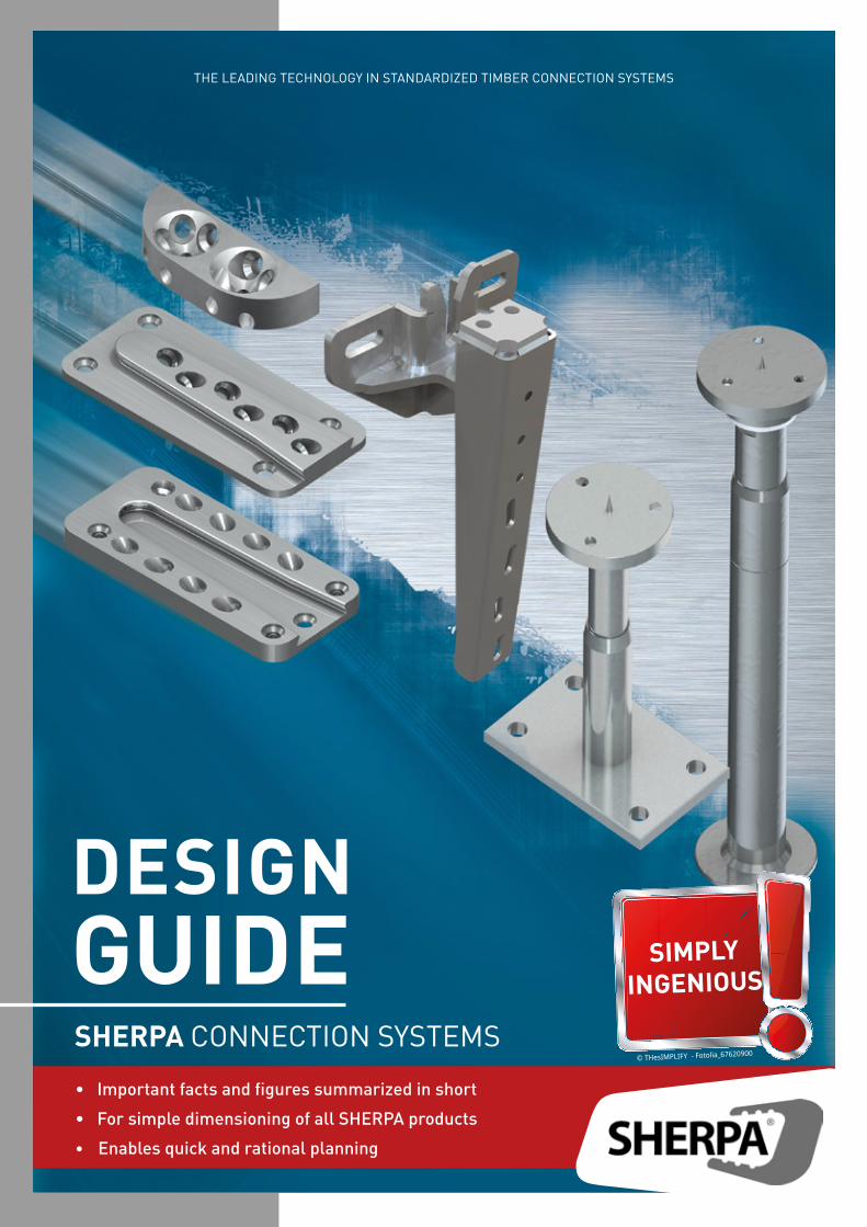
THE LEADING TECHNOLOGY IN STANDARDIZED TIMBER CONNECTION SYSTEMS
DESIGNGUIDE
• Important facts and figures summarized in short
• For simple dimensioning of all SHERPA products
• Enables quick and rational planning
SIMPLYINGENIOUS
SHERPA CONNECTION SYSTEMS© THesIMPLIFY - Fotolia_67620900
2 3
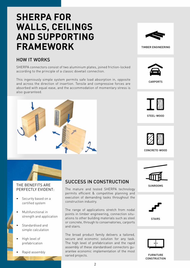
SHERPA FORWALLS, CEILINGSAND SUPPORTINGFRAMEWORK
SUCCESS IN CONSTRUCTIONThe mature and tested SHERPA technology permits efficient & competitive planning and execution of demanding tasks throughout the construction industry.
The range of applications stretch from nodal points in timber engineering, connection situ-ations to other building materials such as steel or concrete, through to conservatories, carports and stairs.
The broad product family delivers a tailored, secure and economic solution for any task. The high level of prefabrication and the rapid assembly of these standardised connectors gu-arantee economic implementation of the most varied projects.
HOW IT WORKS SHERPA connectors consist of two aluminium plates, joined friction-locked according to the principle of a classic dovetail connection.
This ingeniously simple system permits safe load absorption in, opposite and across the direction of insertion. Tensile and compressive forces are absorbed with equal ease, and the accommodation of momentary stress is also guaranteed.
STAIRS
SUNROOMS
FURNITURECONSTRUCTION
CONCRETE-WOOD
STEEL-WOOD
THE BENEFITS AREPERFECTLY EVIDENT:
• Security based on a certified system
• Multifunctional in strength and application
• Standardised and simple calculation
• High level of prefabrication
• Rapid assembly
CARPORTS
TIMBER ENGINEERING

2 3
INGENIOUS SUPPORT
PRELIMINARY RATING TOOLAt any time and in any given place SHERPA users are able to select the best fitting connector with the online pre-measurement tool.
The browser-based soft-ware can be accessed easily and quickly with mobile devices such as smart phones or personal computers.
TENDER TEXTIn order to support tendering clients, SHERPA offers detail and comprehensive boilerplates for standard connectors for timber construction.
These texts can be easily und quicklyadapted to any given connection situation. Minimum requirements regarding load-bearing capacity and appearances as well as rigidness and fire protection are considered.
SHERPA MANUALThe SHERPA manual provides all relevant data required for standardized connections during planning and imple-mentation stages.
The chapter Models gives further information about operating prin-ciples under different loads and stresses. Calculation examples will prove traceability of planning stages.
SOFTWARE CONNECTIONIn order to support SHERPA users during work preparation and scheduling, all connectors can be downloaded in the usual design and woodwork programs.
The whole SHERPA connector product range is available on SHERPA website for down-load as 2D or 3D geometrical files.
2D / 3D
TECHNICAL SUPPORTWhether per e-mail, phone or videoconference - SHERPA users are welcome to contact our experienced support team consisting of civil engineers and practitioners at any time. Support ranges from simply inquiries to select the appropriate connector to on-site trainings and talks with inspection engineers within large-scale projects.
Fon +43 3127 41 983 - 311Fax +43 3127 20 945 218 [email protected]
ENQ
UIR
Y
SOLU
TIO
N
Information on ...
- size of component- quality of wood used- connection angle- load values (design)
... is welcome.
Recommendations for ...
- the best choice of connectors- position- validation- assembly
... and other aspects
Carpenters
Civil engineers
Architects
Do-it-yourself
Trading
Cabinet makers CLIENTS?
DI (FH)Josef Kowal
DIKlemen Klemenak
4 5
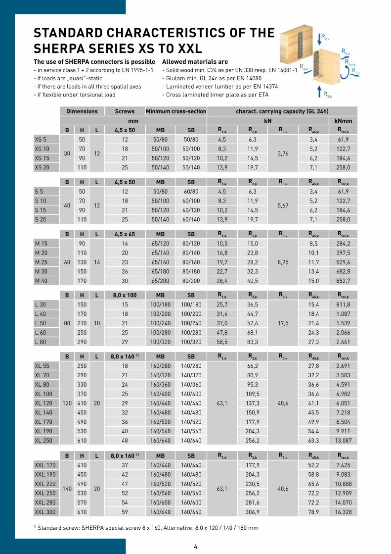
Dimensions Screws Minimum cross-section charact. carrying capacity (GL 24h)
mm kN kNmmB H L 4,5 x 50 MB SB R1,k R2,k R3,k R45,k Rtor,k
XS 5
30
50
12
12 50/80 50/80 4,5 6,3
3,76
3,4 61,9XS 10 70 18 50/100 50/100 8,3 11,9 5,2 122,7XS 15 90 21 50/120 50/120 10,2 14,5 6,2 184,6XS 20 110 25 50/140 50/140 13,9 19,7 7,1 258,0
B H L 4,5 x 50 MB SB R1,k R2,k R3,k R45,k Rtor,k
S 5
40
50
12
12 50/80 60/80 4,5 6,3
5,67
3,4 61,9S 10 70 18 50/100 60/100 8,3 11,9 5,2 122,7S 15 90 21 50/120 60/120 10,2 14,5 6,2 184,6S 20 110 25 50/140 60/140 13,9 19,7 7,1 258,0
B H L 6,5 x 65 MB SB R1,k R2,k R3,k R45,k Rtor,k
M 15
60
90
14
16 65/120 80/120 10,5 15,0
8,95
8,5 284,2M 20 110 20 65/140 80/140 16,8 23,8 10,1 397,5M 25 130 23 65/160 80/160 19,7 28,2 11,7 529,6M 30 150 26 65/180 80/180 22,7 32,3 13,4 682,8M 40 170 30 65/200 80/200 28,4 40,5 15,0 852,7
B H L 8,0 x 100 MB SB R1,k R2,k R3,k R45,k Rtor,k
L 30
80
150
18
15 100/180 100/180 25,7 36,5
17,5
15,4 811,8L 40 170 18 100/200 100/200 31,4 44,7 18,4 1.087L 50 210 21 100/240 100/240 37,0 52,6 21,4 1.539L 60 250 25 100/280 100/280 47,8 68,1 24,3 2.066L 80 290 29 100/320 100/320 58,5 83,3 27,3 2.661
B H L 8,0 x 160 1) MB SB R1,k R2,k R3,k R45,k Rtor,k
XL 55
120
250
20
18 160/280 140/280
63,1
66,2
40,6
27,8 2.691XL 70 290 21 160/320 140/320 80,9 32,2 3.583XL 80 330 24 160/360 140/360 95,3 36,6 4.591XL 100 370 25 160/400 140/400 109,5 36,6 4.982XL 120 410 29 160/440 140/440 137,3 41,1 6.051XL 140 450 32 160/480 140/480 150,9 45,5 7.218XL 170 490 36 160/520 140/520 177,9 49,9 8.504XL 190 530 40 160/560 140/560 204,3 54,4 9.911XL 250 610 48 160/640 140/640 256,2 63,3 13.087
B H L 8,0 x 160 1) MB SB R1,k R2,k R3,k R45,k Rtor,k
XXL 170
140
410
20
37 160/440 160/440
63,1
177,9
40,6
52,2 7.425XXL 190 450 42 160/480 160/480 204,3 58,8 9.083XXL 220 490 47 160/520 160/520 230,5 65,6 10.888XXL 250 530 52 160/560 160/560 256,2 72,2 12.909XXL 280 570 54 160/600 160/600 281,6 72,2 14.070
XXL 300 610 59 160/640 160/640 306,9 78,9 16.328
STANDARD CHARACTERISTICS OF THESHERPA SERIES XS TO XXLThe use of SHERPA connectors is possible- in service class 1 + 2 according to EN 1995-1-1- if loads are „quasi“-static- if there are loads in all three spatial axes- if flexible under torsional load
Allowed materials are- Solid wood min. C24 as per EN 338 resp. EN 14081-1- Glulam min. GL 24c as per EN 14080- Laminated veneer lumber as per EN 14374- Cross laminated timer plate as per ETA
R2,k
R3,k
R1,k
Rtor,kR4,k
R5,k
1) Standard screw: SHERPA special screw 8 x 160, Alternative: 8,0 x 120 / 140 / 180 mm
4 5
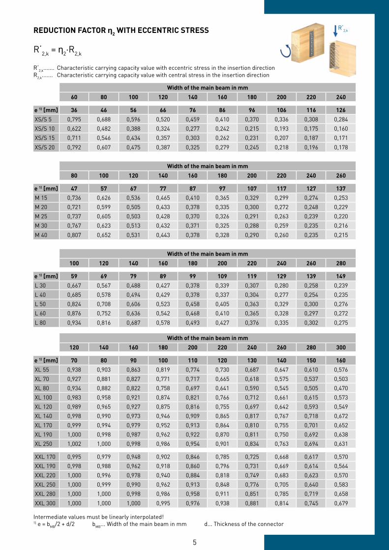
Width of the main beam in mm
60 80 100 120 140 160 180 200 220 240
e 1) [mm] 36 46 56 66 76 86 96 106 116 126XS/S 5 0,795 0,688 0,596 0,520 0,459 0,410 0,370 0,336 0,308 0,284XS/S 10 0,622 0,482 0,388 0,324 0,277 0,242 0,215 0,193 0,175 0,160XS/S 15 0,711 0,546 0,434 0,357 0,303 0,262 0,231 0,207 0,187 0,171
XS/S 20 0,792 0,607 0,475 0,387 0,325 0,279 0,245 0,218 0,196 0,178
Width of the main beam in mm
80 100 120 140 160 180 200 220 240 260
e 1) [mm] 47 57 67 77 87 97 107 117 127 137M 15 0,736 0,626 0,536 0,465 0,410 0,365 0,329 0,299 0,274 0,253M 20 0,721 0,599 0,505 0,433 0,378 0,335 0,300 0,272 0,248 0,229M 25 0,737 0,605 0,503 0,428 0,370 0,326 0,291 0,263 0,239 0,220M 30 0,767 0,623 0,513 0,432 0,371 0,325 0,288 0,259 0,235 0,216
M 40 0,807 0,652 0,531 0,443 0,378 0,328 0,290 0,260 0,235 0,215
Width of the main beam in mm
100 120 140 160 180 200 220 240 260 280
e 1) [mm] 59 69 79 89 99 109 119 129 139 149L 30 0,667 0,567 0,488 0,427 0,378 0,339 0,307 0,280 0,258 0,239L 40 0,685 0,578 0,494 0,429 0,378 0,337 0,304 0,277 0,254 0,235L 50 0,824 0,708 0,606 0,523 0,458 0,405 0,363 0,329 0,300 0,276L 60 0,876 0,752 0,636 0,542 0,468 0,410 0,365 0,328 0,297 0,272
L 80 0,934 0,816 0,687 0,578 0,493 0,427 0,376 0,335 0,302 0,275
Width of the main beam in mm
120 140 160 180 200 220 240 260 280 300
e 1) [mm] 70 80 90 100 110 120 130 140 150 160XL 55 0,938 0,903 0,863 0,819 0,774 0,730 0,687 0,647 0,610 0,576XL 70 0,927 0,881 0,827 0,771 0,717 0,665 0,618 0,575 0,537 0,503XL 80 0,934 0,882 0,822 0,758 0,697 0,641 0,590 0,545 0,505 0,470XL 100 0,983 0,958 0,921 0,874 0,821 0,766 0,712 0,661 0,615 0,573XL 120 0,989 0,965 0,927 0,875 0,816 0,755 0,697 0,642 0,593 0,549XL 140 0,998 0,990 0,973 0,946 0,909 0,865 0,817 0,767 0,718 0,672XL 170 0,999 0,994 0,979 0,952 0,913 0,864 0,810 0,755 0,701 0,652XL 190 1,000 0,998 0,987 0,962 0,922 0,870 0,811 0,750 0,692 0,638XL 250 1,002 1,000 0,998 0,986 0,954 0,901 0,834 0,763 0,694 0,631
XXL 170 0,995 0,979 0,948 0,902 0,846 0,785 0,725 0,668 0,617 0,570XXL 190 0,998 0,988 0,962 0,918 0,860 0,796 0,731 0,669 0,614 0,564XXL 220 1,000 0,996 0,978 0,940 0,884 0,818 0,749 0,683 0,623 0,570XXL 250 1,000 0,999 0,990 0,962 0,913 0,848 0,776 0,705 0,640 0,583XXL 280 1,000 1,000 0,998 0,986 0,958 0,911 0,851 0,785 0,719 0,658
XXL 300 1,000 1,000 1,000 0,995 0,976 0,938 0,881 0,814 0,745 0,679
REDUCTION FACTOR ƞ2 WITH ECCENTRIC STRESS
Intermediate values must be linearly interpolated!1) e = bMB/2 + d/2 bMB... Width of the main beam in mm d... Thickness of the connector
R‘2,k = η2·R2,k
R‘2,k
R‘2,k....... Characteristic carrying capacity value with eccentric stress in the insertion directionR2,k....... Characteristic carrying capacity value with central stress in the insertion direction
6 7
Dimensions Values R2,d in kN
Geometry Screws to timber SB to concrete for C 25/30 to steelmm Pcs. mm kN HECO MMS-F FH II-SK HILTI HIS-N DIN 7991
B H L 6,5 x 65 GL 24h kmod /γM 2) Pcs. 7,5x60 Pcs. M6 8.8
M 15 CS 1)
60
90
20
9 80/120 9,6 4 12,1 4 32M 20 CS 110 11 80/140 15,2 4 13,6 4 32M 25 CS 1) 130 13 80/160 18,0 4 15,1 4 32M 30 CS 150 15 80/180 20,8 6 16,6 6 48
M 40 CS 170 17 80/200 25,9 6 18,1 6 48
B H L 8,0 x 100 GL 24h kmod /γM 2) Pcs. 10x80 Pcs. M10 Pcs. M10 8.8
L 30 CS
80
150
29
9 100/180 23,4 4 39,5 4 73,6 4 89L 40 CS 1) 170 11 100/200 28,6 4 42,7 4 73,6 4 89L 50 CS 210 13 100/240 33,7 6 49,7 6 110,4 6 133,6L 60 CS 250 15 100/280 43,6 6 56,5 6 110,4 6 133,6
L 80 CS 290 17 100/320 53,3 6 63,3 6 110,4 6 133,6
B H L 8,0 x 160 GL 24h kmod /γM 2) Pcs. 10x80 Pcs. 12/15 Pcs. M12 Pcs. M10 8.8
XL 55 CS
120
250
29
10 160/280 42,4 6 63,6 4 56,8 4 104,0 6 133,6XL 70 CS 1) 290 12 160/320 51,8 6 64,0 4 64,2 4 104,0 6 133,6XL 80 CS 1) 330 14 160/360 61,0 8 79,3 6 71,5 6 142,2 8 178,2XL 100 CS 370 14 160/400 70,1 8 85,3 6 78,8 6 151,9 8 178,2XL 120 CS 410 16 160/440 87,9 8 85,3 6 86,1 6 156,0 8 178,2XL 140 CS 450 18 160/480 96,6 8 85,3 6 93,5 6 156,0 8 178,2XL 170 CS 1) 490 20 160/520 113,9 8 85,3 6 99,0 6 156,0 8 178,2XL 190 CS 530 22 160/560 130,8 10 106,7 8 108,1 8 190,8 10 222,7
XL 250 CS 610 26 160/640 164,0 10 106,7 8 122,3 8 208,0 10 222,7
B H L 8,0 x 160 GL 24h kmod /γM 2) Pcs. 10x80 Pcs. M10 Pcs. M10 8.8
XXL 170 CS 1)
140
410
29
21 160/440 113,9 8 85,3 8 147,2 14 311,8XXL 190 CS 1) 450 24 160/480 130,8 8 85,3 8 147,2 14 311,8XXL 220 CS 1) 490 27 160/520 147,5 10 106,7 10 180,1 18 400,9XXL 250 CS 1) 530 30 160/560 164,0 10 106,7 10 184,0 18 400,9XXL 280 CS 1) 570 30 160/600 180,2 10 106,7 10 184,0 18 400,9
XXL 300 CS 1) 610 33 160/640 196,4 10 106,7 10 184,0 18 400,9
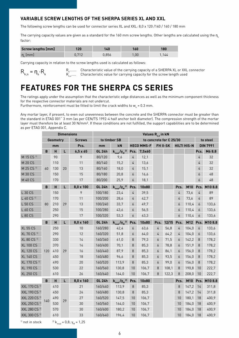
FEATURES FOR THE SHERPA CS SERIESThe ratings apply under the assumption that the characteristic edge distances as well as the minimum component thickness for the respective connector materials are not undercut.Furthermore, reinforcement must be fitted to limit the crack widths to wk = 0.3 mm.
Any mortar layer, if present, to even out unevenness between the concrete and the SHERPA connector must be greater than the standard in ETAG 001“ 3 mm (as per CEN/TS 1992-4 half anchor bolt diameter). The compression strength of the mortar layer must therefore be at least 30 N/mm². If these conditions are not fulfilled, the support capabilities are to be determined as per ETAG 001, Appendix C.
1) not in stock 2) kmod = 0,8; γM = 1,25
VARIABLE SCREW LENGTHS OF THE SHERPA SERIES XL AND XXLThe following screw lengths can be used for connector series XL and XXL: 8,0 x 120 /140 / 160 / 180 mm
The carrying capacity values are given as a standard for the 160 mm screw lengths. Other lengths are calculated using the ηs factor:
Screw lengths [mm] 120 140 160 180
ηs [mm] 0,712 0,856 1,00 1,144
Carrying capacity in relation to the screw lengths used is calculated as follows:
Rk....... Characteristic value of the carrying capacity of a SHERPA XL or XXL connectorRk;s..... Characteristic value for carrying capacity for the screw length usedRk;s = ηs·Rk
6 7
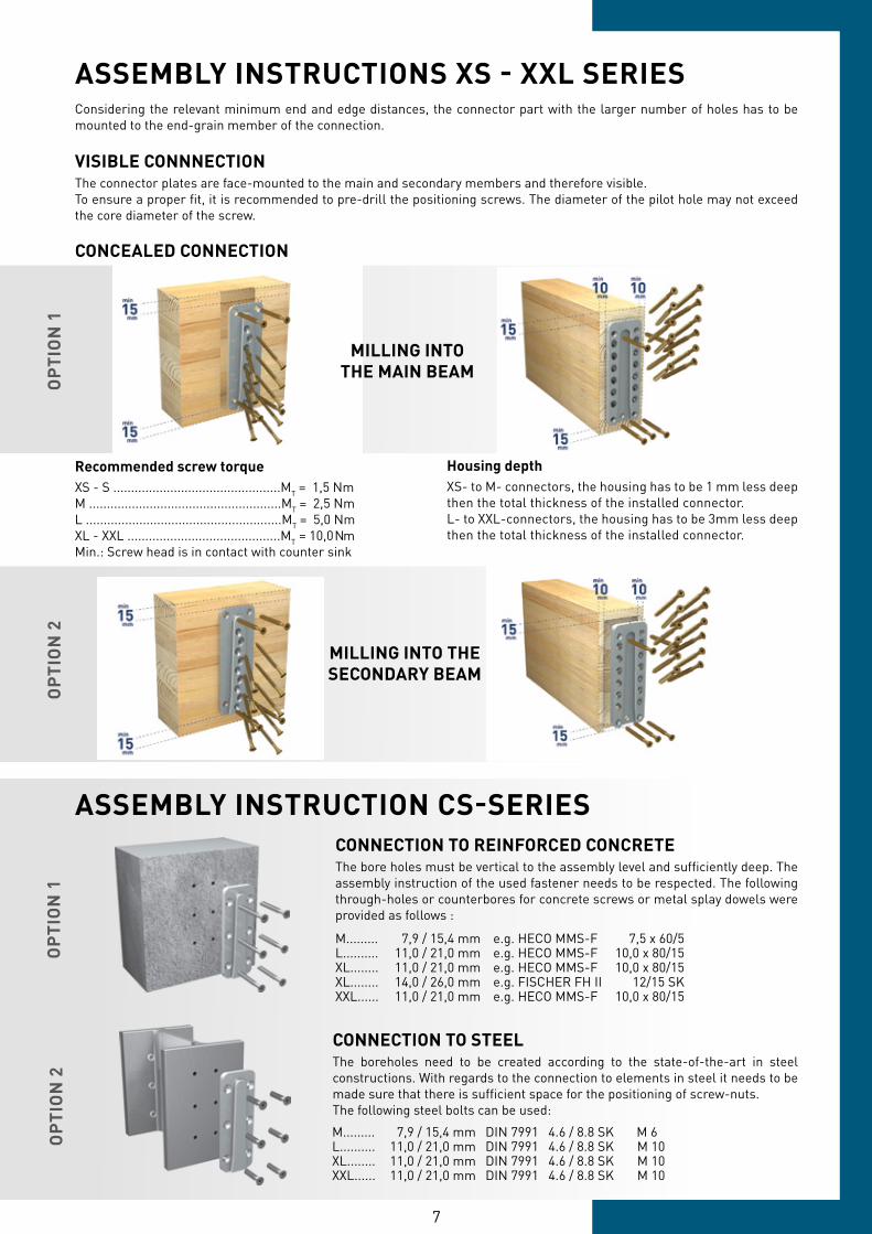
Housing depthXS- to M- connectors, the housing has to be 1 mm less deepthen the total thickness of the installed connector.L- to XXL-connectors, the housing has to be 3mm less deepthen the total thickness of the installed connector.
Recommended screw torqueXS - S ...............................................MT = 1,5 NmM ......................................................MT = 2,5 NmL .......................................................MT = 5,0 NmXL - XXL ...........................................MT = 10,0 NmMin.: Screw head is in contact with counter sink
Considering the relevant minimum end and edge distances, the connector part with the larger number of holes has to be mounted to the end-grain member of the connection.
VISIBLE CONNNECTIONThe connector plates are face-mounted to the main and secondary members and therefore visible.To ensure a proper fit, it is recommended to pre-drill the positioning screws. The diameter of the pilot hole may not exceed the core diameter of the screw.
ASSEMBLY INSTRUCTIONS XS - XXL SERIESO
PTI
ON
1O
PTI
ON
2O
PTI
ON
1O
PTI
ON
2
M......... 7,9 / 15,4 mm e.g. HECO MMS-F 7,5 x 60/5L.......... 11,0 / 21,0 mm e.g. HECO MMS-F 10,0 x 80/15XL........ 11,0 / 21,0 mm e.g. HECO MMS-F 10,0 x 80/15XL........ 14,0 / 26,0 mm e.g. FISCHER FH II 12/15 SKXXL...... 11,0 / 21,0 mm e.g. HECO MMS-F 10,0 x 80/15
M......... 7,9 / 15,4 mm DIN 7991 4.6 / 8.8 SK M 6L.......... 11,0 / 21,0 mm DIN 7991 4.6 / 8.8 SK M 10XL........ 11,0 / 21,0 mm DIN 7991 4.6 / 8.8 SK M 10XXL...... 11,0 / 21,0 mm DIN 7991 4.6 / 8.8 SK M 10
CONNECTION TO REINFORCED CONCRETEThe bore holes must be vertical to the assembly level and sufficiently deep. The assembly instruction of the used fastener needs to be respected. The following through-holes or counterbores for concrete screws or metal splay dowels were provided as follows :
ASSEMBLY INSTRUCTION CS-SERIES
CONNECTION TO STEELThe boreholes need to be created according to the state-of-the-art in steel constructions. With regards to the connection to elements in steel it needs to be made sure that there is sufficient space for the positioning of screw-nuts.The following steel bolts can be used:
CONCEALED CONNECTION
MILLING INTOTHE MAIN BEAM
MILLING INTO THESECONDARY BEAM
8 9
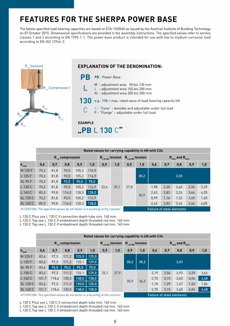
FEATURES FOR THE SHERPA POWER BASEThe below-specified load-bearing capacities are based on ETA-15/0540 as issued by the Austrian Institute of Building Technology on 07 October 2015. Dimensional specifications are provided in the assembly instructions. The specified values refer to service classes 1 and 2 according to EN 1995-1-1. The power base product is intended for use with low to medium corrosive load according to EN ISO 12944-2.
Rated values for carrying capability in kN with C24
R1,d compression R1,d;160 tension R1,d;180 tension R23,d and R45,d
kmod 0,6 0,7 0,8 0,9 1,0 0,9 1,0 0,9 1,0 0,6 0,7 0,8 0,9 1,0
M 125 F 70,2 81,8 93,5 105,2 116,9
22,6 25,1 27,8
30,2 2,03L 125 F 70,2 81,8 93,5 105,2 116,9XL 95 F 70,2 81,8 93,5 95,0 95,0L 130 C 70,2 81,8 93,5 105,2 116,9
30,9
1,98 2,30 2,63 2,96 3,29L 140 C 85,5 99,8 114,0 128,3 138,0 2,43 2,83 3,24 3,64 4,05XL 120 C 70,2 81,8 93,5 105,2 116,9 0,99 1,16 1,32 1,49 1,65XL 140 C 85,5 99,8 114,0 128,3 138,0 2,43 2,83 3,24 3,64 4,05ATTENTION: The specified values do not factor in a buckling of the column! Failure of steel elements
L 130 C Plus see L 130 C if connection depth tube min. 160 mmL 120 C Top see L 120 C if embedment depth threaded rod min. 160 mmL 130 C Top see L 130 C if embedment depth threaded rod min. 160 mm
Rated values for carrying capability in kN with C24
R1,d compression R1,d;160 tension R1,d;180 tension R23,d and R45,d
kmod 0,6 0,7 0,8 0,9 1,0 0,9 1,0 0,9 1,0 0,6 0,7 0,8 0,9 1,0
M 125 F 83,4 97,3 111,2 125,0 125,0
25,1 27,9
30,2 30,2 2,03L 125 F 83,4 97,3 111,2 125,1 129,0XL 95 F 83,4 95,0 95,0 95,0 95,0L 130 C 83,4 97,3 111,2 125,1 129,0
30,9 34,3
2,19 2,56 2,93 3,29 3,66L 140 C 101,7 118,6 135,5 138,0 138,0 2,70 3,15 3,60 4,04 4,48XL 120 C 83,4 97,3 111,2 120,0 120,0 1,10 1,29 1,47 1,65 1,84XL 140 C 101,7 118,6 135,5 138,0 138,0 2,70 3,15 3,60 4,04 4,48ATTENTION: The specified values do not factor in a buckling of the column! Failure of steel elements
L 130 C Plus see L 130 C if connection depth tube min. 160 mmL 120 C Top see L 120 C if embedment depth threaded rod min. 160 mmL 130 C Top see L 130 C if embedment depth threaded rod min. 160 mm
R1,d (compression )
R1,d (tension)
R3,d
R2,d
R4,d
R5,d
EXPLANATION OF THE DENOMINATION:
PBL
130C
EXAMPLE
PB - Power Base
M - adjustment area 90 bis 130 mmL - adjustment area 150 bis 200 mmXL - adjustment area 200 bis 300 mm
e.g.: 130 = max. rated value of load-bearing capacity kN
C - “Cone” - divisible and adjustable under full loadF - “Flange” - adjustable under full load
„PB L 130 C“
8 9
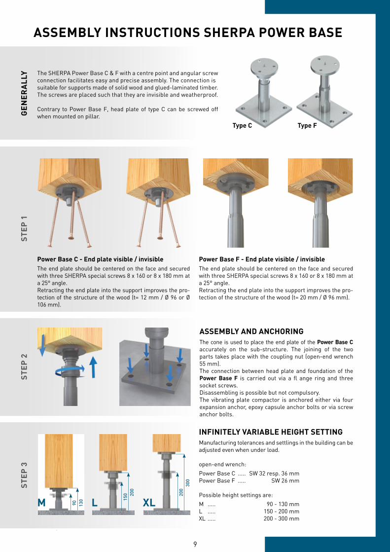
The SHERPA Power Base C & F with a centre point and angular screwconnection facilitates easy and precise assembly. The connection issuitable for supports made of solid wood and glued-laminated timber. The screws are placed such that they are invisible and weatherproof.
Contrary to Power Base F, head plate of type C can be screwed off when mounted on pillar.
STEP
3
M 90 130 L 15
0 200
XL
200
300
STEP
1
Power Base F - End plate visible / invisibleThe end plate should be centered on the face and secured with three SHERPA special screws 8 x 160 or 8 x 180 mm at a 25° angle.Retracting the end plate into the support improves the pro-tection of the structure of the wood (t= 20 mm / Ø 96 mm).
Power Base C - End plate visible / invisibleThe end plate should be centered on the face and secured with three SHERPA special screws 8 x 160 or 8 x 180 mm at a 25° angle.Retracting the end plate into the support improves the pro-tection of the structure of the wood (t= 12 mm / Ø 96 or Ø 106 mm).
STEP
2
ASSEMBLY AND ANCHORINGThe cone is used to place the end plate of the Power Base C accurately on the sub-structure. The joining of the two parts takes place with the coupling nut (open-end wrench 55 mm).The connection between head plate and foundation of the Power Base F is carried out via a fl ange ring and three socket screws.Disassembling is possible but not compulsory.The vibrating plate compactor is anchored either via four expansion anchor, epoxy capsule anchor bolts or via screw anchor bolts.
INFINITELY VARIABLE HEIGHT SETTINGManufacturing tolerances and settlings in the building can be adjusted even when under load.
open-end wrench:Power Base C ..... SW 32 resp. 36 mmPower Base F ..... SW 26 mm
Possible height settings are: M ..... 90 - 130 mmL ..... 150 - 200 mmXL ..... 200 - 300 mm
ASSEMBLY INSTRUCTIONS SHERPA POWER BASEG
ENER
ALL
Y
Type C Type F
10 11
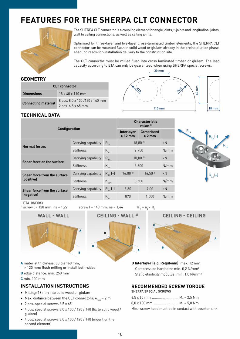
GEOMETRYCLT connector
Dimensions 18 x 40 x 110 mm
Connecting material8 pcs. 8,0 x 100 /120 / 140 mm2 pcs. 6,5 x 65 mm
TECHNICAL DATA
Configuration
Characteristicvalue 1)
Interlayer≤ 12 mm
Compriband≤ 2 mm
Normal forcesCarrying capability R1,k 18,80 2) kN
Stiffness Kser 9.750 N/mm
Shear force on the surfaceCarrying capability R2,k 10,00 2) kN
Stiffness Kser 3.300 N/mm
Shear force from the surface(positive)
Carrying capability R3,k·(+) 16,00 2) 16,50 2) kN
Stiffness Kser 3.600 N/mm
Shear force from the surface(negative)
Carrying capability R3,k·(-) 5,30 7,00 kN
Stiffness Kser 870 1.000 N/mm1) ETA 18/00832) screw l = 120 mm: ns = 1,22 screw l = 140 mm: ns = 1,44 R‘k = ns ∙ Rk
110 mm 18 mm
30 mm
R40R40
40 m
m
The SHERPA CLT connector is a coupling element for angle joints, t-joints and longitudinal joints, wall to ceiling connections, as well as ceiling joints.
Optimised for three-layer and five-layer cross-laminated timber elements, the SHERPA CLT connector can be mounted flush in solid wood or glulam already in the preinstallation phase, enabling ready-for-installation delivery to the construction site.
The CLT connector must be milled flush into cross laminated timber or glulam. The load capacity according to ETA can only be guaranteed when using SHERPA special screws.
FEATURES FOR THE SHERPA CLT CONNECTOR
R3,k∙(+)
R3,k∙(-)
R1,k
R2,k
INSTALLATION INSTRUCTIONS• Milling: 18 mm into solid wood or glulam• Max. distance between the CLT connectors: emax = 2 m• 2 pcs. special screws 6.5 x 65• 4 pcs. special screws 8.0 x 100 / 120 / 140 (fix to solid wood / glulam)• 4 pcs. special screws 8.0 x 100 / 120 / 140 (mount on the second element)
RECOMMENDED SCREW TORQUESHERPA SPECIAL SCREWS
6,5 x 65 mm ............................MT = 2,5 Nm8,0 x 100 mm ..........................MT = 5,0 NmMin.: screw head must be in contact with counter sink
A
B
A
A B
D
A
C
B
A material thickness: 80 bis 160 mm; > 120 mm: flush milling or install both-sidedB edge distance: min. 250 mmC min. 100 mm
D Interlayer (e.g. Regufoam): max. 12 mm Compression hardness: min. 0,2 N/mm² Static elasticity modulus: min. 1,0 N/mm²
WALL - WALL CEILING - WALL 2) CEILING - CEILING
10 11
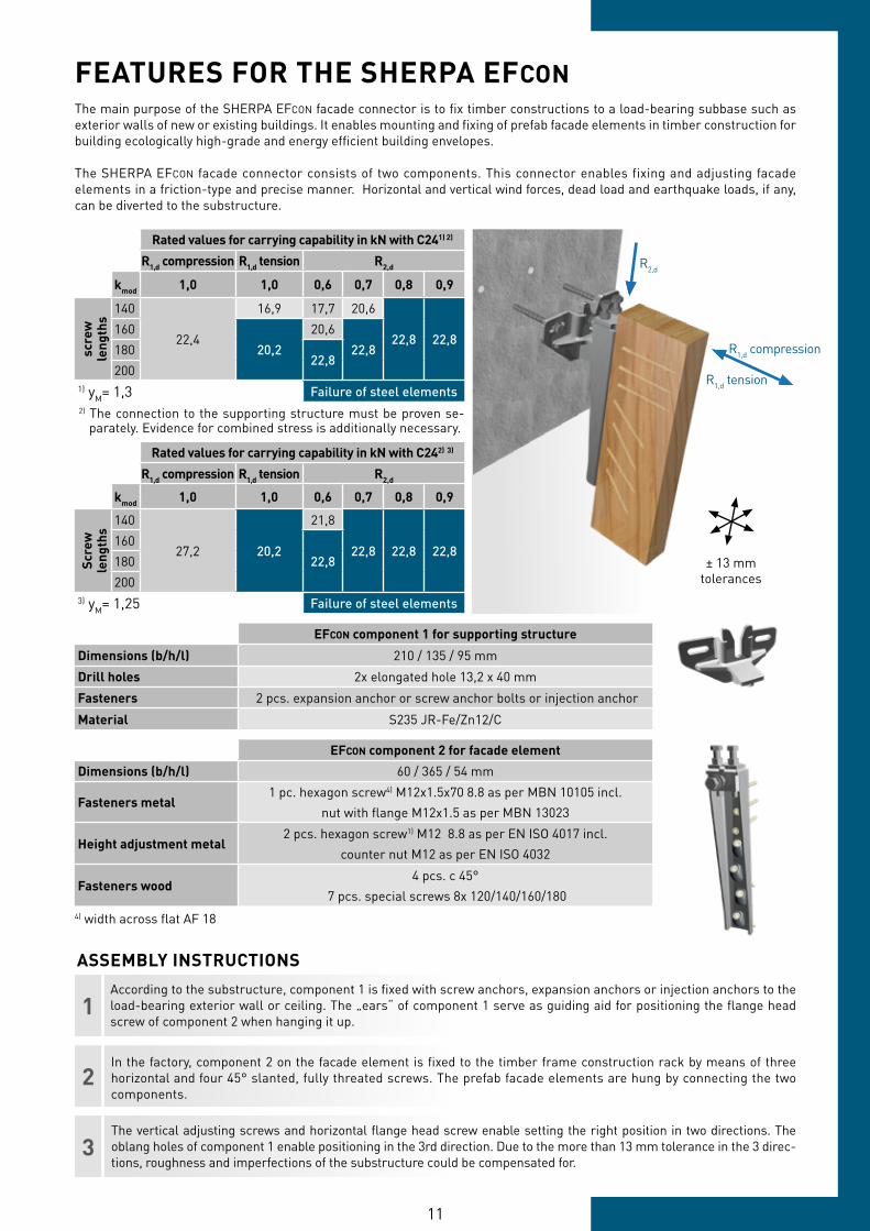
FEATURES FOR THE SHERPA EFCON
Rated values for carrying capability in kN with C241) 2)
R1,d compression R1,d tension R2,d
kmod 1,0 1,0 0,6 0,7 0,8 0,9
scre
w
leng
ths
140
22,4
16,9 17,7 20,6
22,8 22,8160
20,220,6
22,818022,8
2001) yM= 1,3 Failure of steel elements
The main purpose of the SHERPA EFCON facade connector is to fix timber constructions to a load-bearing subbase such as exterior walls of new or existing buildings. It enables mounting and fixing of prefab facade elements in timber construction for building ecologically high-grade and energy efficient building envelopes.
The SHERPA EFCON facade connector consists of two components. This connector enables fixing and adjusting facade elements in a friction-type and precise manner. Horizontal and vertical wind forces, dead load and earthquake loads, if any, can be diverted to the substructure.
Rated values for carrying capability in kN with C242) 3)
R1,d compression R1,d tension R2,d
kmod 1,0 1,0 0,6 0,7 0,8 0,9
Scre
w
leng
ths
140
27,2 20,2
21,8
22,8 22,8 22,8160
22,8180200
3) yM= 1,25 Failure of steel elements
R1,k
EFCON component 1 for supporting structure
Dimensions (b/h/l) 210 / 135 / 95 mm
Drill holes 2x elongated hole 13,2 x 40 mm
Fasteners 2 pcs. expansion anchor or screw anchor bolts or injection anchor
Material S235 JR-Fe/Zn12/C
EFCON component 2 for facade element
Dimensions (b/h/l) 60 / 365 / 54 mm
Fasteners metal1 pc. hexagon screw4) M12x1.5x70 8.8 as per MBN 10105 incl.
nut with flange M12x1.5 as per MBN 13023
Height adjustment metal2 pcs. hexagon screw1) M12 8.8 as per EN ISO 4017 incl.
counter nut M12 as per EN ISO 4032
Fasteners wood4 pcs. c 45°
7 pcs. special screws 8x 120/140/160/1804) width across flat AF 18
2) The connection to the supporting structure must be proven se- parately. Evidence for combined stress is additionally necessary.
The vertical adjusting screws and horizontal flange head screw enable setting the right position in two directions. The oblang holes of component 1 enable positioning in the 3rd direction. Due to the more than 13 mm tolerance in the 3 direc-tions, roughness and imperfections of the substructure could be compensated for.
In the factory, component 2 on the facade element is fixed to the timber frame construction rack by means of three horizontal and four 45° slanted, fully threated screws. The prefab facade elements are hung by connecting the two components.
2
3
According to the substructure, component 1 is fixed with screw anchors, expansion anchors or injection anchors to the load-bearing exterior wall or ceiling. The „ears“ of component 1 serve as guiding aid for positioning the flange head screw of component 2 when hanging it up.
1
R1,d tension
R1,d compression
ASSEMBLY INSTRUCTIONS
± 13 mmtolerances
R2,d
SHERPA Connection Systems GmbHBadl 31
A-8130 Frohnleiten
SHERPA-HOTLINE International:Service +43 3127 41 983
Technical Support: DW 311
authorized retailer
SAFETY THROUGH ANAPPROVED SYSTEM
MULTIFUNCTIONAL INSTRENGTH AND USE
STANDARDIZED ANDSIMPLE EVALUATION
A HIGH DEGREE OFPRE-FABRICATION
QUICK ASSEMBLY
THE ADVANTAGESARE CLEAR:
Des
ign
Gui
de_0
3041
8
www.facebook.com/SHERPAConnectorwww.youtube.com/SHERPAConnectorwww.twitter.com/SHERPAConnectorwww.instagram.com/SHERPAConnector
Website >>