design guide - ledalite guide response daylight ... controls to your lighting designs. ... just...
TRANSCRIPT

Design Guide
Response Daylight Design Guide © 2011 Philips Ledalite. All rights reserved. L0266

2Response Daylight Design Guide © 2011 Philips Ledalite. All rights reserved. L0266 Rev. 05.11
Introduction
Response Daylight offers a simple and affordable way to apply daylight controls to your lighting designs.
Simple to specify
Specifying Response Daylight is as easy as specifying any 1cct fixture. The sensors are completely integrated in Philips Ledalite luminaires with subtle aesthetics and simple circuitry so you don’t have to specify standalone systems, low voltage wiring schemes or costly power packs. Just design the lighting as usual and indicate which fixtures require daylight controls.
Virtually no commissioning
Late-night commissioning and third-party installers are a thing of the past. Response Daylight sensors are factory pre-calibrated for most typical lighting applications right out of the box – just plug in the fixture. If your space does require some fine-tuning in the field, Response Daylight sensors are easily adjusted onsite.
About this GuideThis guide reviews the following topics:
• Understanding Control Zones
• Best Practices
• Suspended Applications
• Recessed Applications
• Planning and Specifying
Additional ResourcesThe following resources are available for dowload from www.Philips Ledalite.com/response:
• Response Daylight Brochure
• Sensor Specifications
• Field Guide
• Response Daylight CAD Luminaire Library
• Response Daylight Product Selectors
3Response Daylight Design Guide © 2011 Philips Ledalite. All rights reserved. L0266 Rev. 05.11
Understanding Control Zones
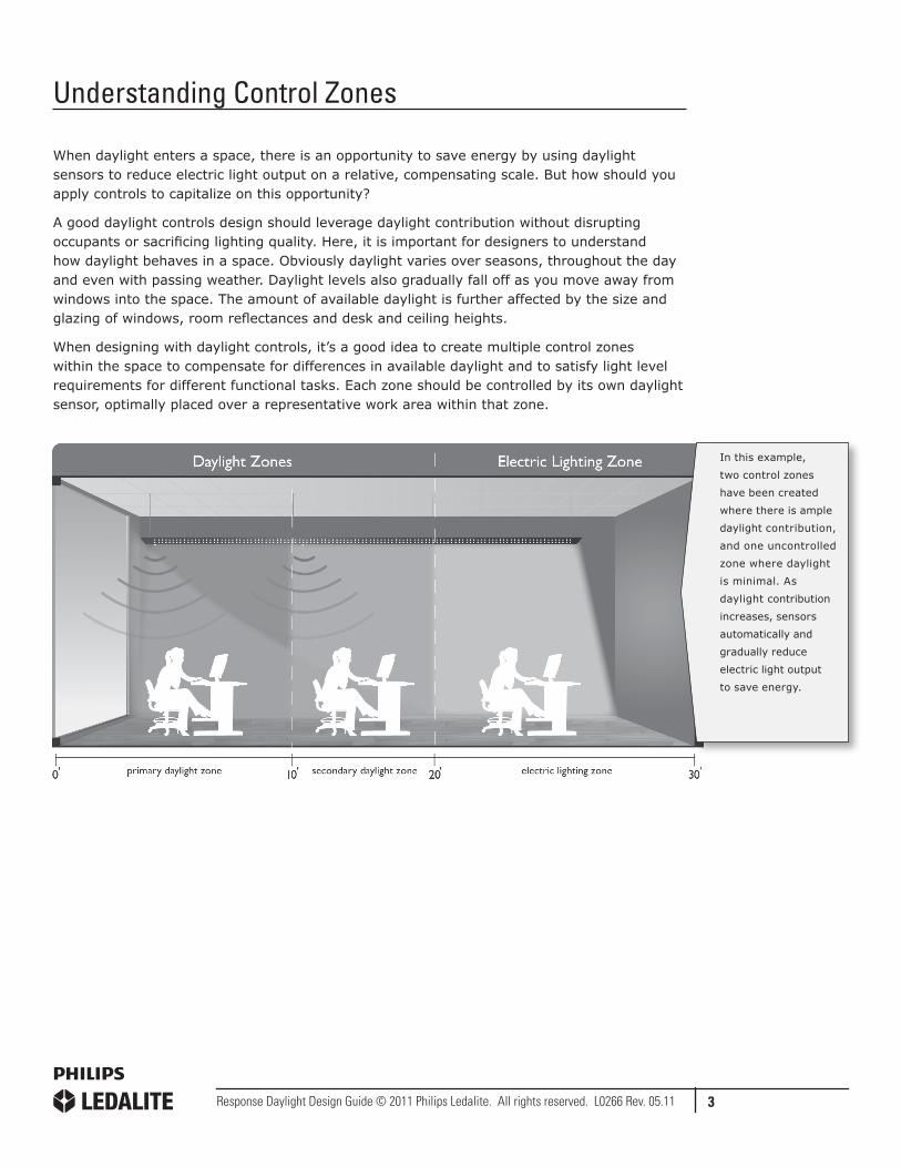
When daylight enters a space, there is an opportunity to save energy by using daylight sensors to reduce electric light output on a relative, compensating scale. But how should you apply controls to capitalize on this opportunity?
A good daylight controls design should leverage daylight contribution without disrupting occupants or sacrificing lighting quality. Here, it is important for designers to understand how daylight behaves in a space. Obviously daylight varies over seasons, throughout the day and even with passing weather. Daylight levels also gradually fall off as you move away from windows into the space. The amount of available daylight is further affected by the size and glazing of windows, room reflectances and desk and ceiling heights.
When designing with daylight controls, it’s a good idea to create multiple control zones within the space to compensate for differences in available daylight and to satisfy light level requirements for different functional tasks. Each zone should be controlled by its own daylight sensor, optimally placed over a representative work area within that zone.
In this example,
two control zones
have been created
where there is ample
daylight contribution,
and one uncontrolled
zone where daylight
is minimal. As
daylight contribution
increases, sensors
automatically and
gradually reduce
electric light output
to save energy.

4Response Daylight Design Guide © 2011 Philips Ledalite. All rights reserved. L0266 Rev. 05.11
15 FEET
Daylit Zone*
Best Practices
Every space is unique and, as such, every space will have different requirements for applying daylight controls. When designing with Response Daylight, Philips Ledalite recommends running calculations on a project-specific basis. However there are some general guidelines you should follow to optimize sensor placement within any space.
Optimal sensor placementSensor should be located
• Between 6-10’ from window
• Over representative work surfaces
Sensor should not be located
• Outside the daylit zone* (typically beyond 15’ from window)
• Over very dark surfaces (e.g. dark carpet or furniture)
• Over highly reflective surfaces (e.g. polished floors or tables)
*NOTE: The size of the daylit zone is primarily a function of the size and exposure of windows. In a typical space, areas beyond 15’ do not usually receive enough daylight contribution to warrant controls. Within the daylit zone, designers can create multiple control zones depending on the design of the space and the demands of functional tasks.
Important
• Controlled fixtures must be placed so that there is at least five feet between sensors
Specific applications where Response Daylight is not recommended• If a desired light level must be maintained with an accuracy greater than 10%, sensors with a higher performance should be used.
• If the building contains a wide variety of atypical rooms (e.g., in shape and decoration) with individual commissioning requirements, controls with optimized commissioning tools should be used.
at least 5’ between sensors
CORRECT INCORRECT
less than 5’ between sensors
5Response Daylight Design Guide © 2011 Philips Ledalite. All rights reserved. L0266 Rev. 05.11
Suspended Applications
Philips Ledalite’s suspended products with Response Daylight offer architects and lighting designers critical flexibility and functionality for designing spaces with daylight control.
Philips Ledalite suspended luminaires are themselves highly flexible, modular lighting systems designed for a wide range of applications and layouts. Most luminaires are available in 4ft, 8ft and 12ft modules with a range of lamping options (1 – 4 lamps depending on the product). Different modules can be joined together to form continuous runs of various lengths (see page 8 for details).
When integrated with Response Daylight sensors, Philips Ledalite suspended lighting systems can be configured to accommodate almost any application. Response Daylight-controlled modules can be combined with non-controlled modules in a wide variety of configurations.
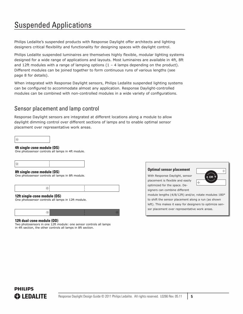
Sensor placement and lamp controlResponse Daylight sensors are integrated at different locations along a module to allow daylight dimming control over different sections of lamps and to enable optimal sensor placement over representative work areas.
4ft single-zone module (DS)One photosensor controls all lamps in 4ft module.
8ft single-zone module (DS)One photosensor controls all lamps in 8ft module.
12ft single-zone module (DS)One photosensor controls all lamps in 12ft module.
12ft dual-zone module (DD)Two photosensors in one 12ft module: one sensor controls all lamps in 4ft section, the other controls all lamps in 8ft section.
Optimal sensor placementWith Response Daylight, sensor
placement is flexible and easily
optimized for the space. De-
signers can combine different
module lengths (4/8/12ft) and/or, rotate modules 180°
to shift the sensor placement along a run (as shown
left). This makes it easy for designers to optimize sen-
sor placement over representative work areas.

6Response Daylight Design Guide © 2011 Philips Ledalite. All rights reserved. L0266 Rev. 05.11
Application 112ft single-zone modules parallel to window. Typical classroom layout.
Two 12ft single-zone modules are joined in a 24ft run that is suspended parallel to the window. In addition, two 12ft non-controlled modules are joined in a 24ft run that is suspended in the area outside the typical daylit zone (beyond 15’ from window) where daylight contribution is negligible.
Application 212ft single-zone modules perpendicular to window. Typical open office layout.
12ft single-zone modules are joined with 12ft non-controlled modules to create 24ft runs suspended perpendicular to the window.
The 12ft single-zone approach (with one sensor dimming all lamps equally in a 12ft module) is a simple way to save energy, but it does not compensate for daylight falloff as accurately as a dual-zone approach.
Controlled modules can be rotated
180° to optimize sensor placement
over representative work areas.

7Response Daylight Design Guide © 2011 Philips Ledalite. All rights reserved. L0266 Rev. 05.11
Application 312ft dual-zone modules perpendicular to window. Typical open office layout.
12ft dual-zone modules are joined with 12ft non-controlled modules to create 24ft runs suspended perpendicular to window.
The 12ft dual-zone approach (with two sensors measuring daylight and adjusting two separate sections of lamps accordingly) provides accurate compensation for daylight falloff throughout the space.
Application 48ft single-zone modules (configured for dual-zone controls) perpendicular to window. Typical open office layout.
24ft runs are created by joining two 8ft single-zone modules (each with one sensor that controls all lamps in the module) and one 8ft non-controlled module.
Combining two 8ft single-zone modules to create dual-zone controls provides accurate compensation for daylight falloff throughout the space. This application extends daylight dimming beyond the typical daylit zone (15’ from window) which may be suitable for spaces with large windows, high ceilings and/or low furniture.
Controlled modules can be rotated
180° to optimize sensor placement
over representative work areas.
Controlled modules can be rotated
180° to optimize sensor placement
over representative work areas.

8Response Daylight Design Guide © 2011 Philips Ledalite. All rights reserved. L0266 Rev. 05.11
How to Make Runs
Module lengthsPhilips Ledalite suspended products are available in 4/8/12ft modules. It’s important to note that actual module lengths and mounting distances vary slightly depending on the product. Consult product spec sheets for details.
4'
8'
12'
Endcap DimensionsEach run requires two endcaps, and each endcap adds to the length of a run. Consult product spec sheets for endcap dimensions.
16'
20'
24'
28'
8'8'
12'8'
12'12'
8'12'8'
Making runs You can create continuous runs of various lengths by joining different modules together. The graphic (below) and the table (right) show some common run configurations using different modules. Remember to consult product spec sheets for exact module lengths and mounting distances.
Run Configuration Table
*NOTE: Run lengths provided here are nominal. Actual module lengths vary by product and endcaps. Consult product spec sheets for exact dimensions.
Run Length* 4’ 8’ 12’
16’ 2
20’ 1 1
24’ 2
28’ 2 1
32’ 1 2
36’ 3
40’ 2 2
44’ 1 3
48’ 4
52’ 2 3
56’ 1 4
60’ 5
64’ 2 4
68‘ 1 5
72’ 6
76’ 2 5
80’ 1 6
84’ 7
88’ 2 6
92’ 1 7
96’ 8
100’ 2 7
9Response Daylight Design Guide © 2011 Philips Ledalite. All rights reserved. L0266 Rev. 05.11
Recessed Applications
Philips Ledalite’s recessed luminaires with MesoOptics® technology are a natural fit for architects and lighting designers who want to bring the best of nature’s luminous aesthetics to indoor environments.
These innovative luminaires provide unique optical control capabilities, exceptional visual comfort and dramatic energy savings over conventional recessed systems. They are available in a range of sizes and lamping options and can be installed in continuous rows or as standalone units in a grid.
When integrated with Response Daylight, these luminaires provide even more energy efficiency while also offering design flexibility and simplicity for your daylighting designs.
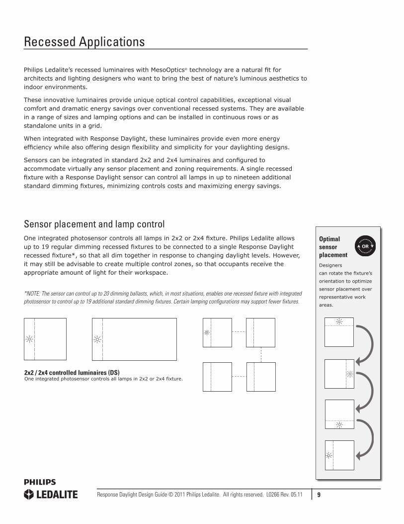
Sensors can be integrated in standard 2x2 and 2x4 luminaires and configured to accommodate virtually any sensor placement and zoning requirements. A single recessed fixture with a Response Daylight sensor can control all lamps in up to nineteen additional standard dimming fixtures, minimizing controls costs and maximizing energy savings.
Sensor placement and lamp controlOne integrated photosensor controls all lamps in 2x2 or 2x4 fixture. Philips Ledalite allows up to 19 regular dimming recessed fixtures to be connected to a single Response Daylight recessed fixture*, so that all dim together in response to changing daylight levels. However, it may still be advisable to create multiple control zones, so that occupants receive the appropriate amount of light for their workspace.
*NOTE: The sensor can control up to 20 dimming ballasts, which, in most situations, enables one recessed fixture with integrated photosensor to control up to 19 additional standard dimming fixtures. Certain lamping configurations may support fewer fixtures.
2x2 / 2x4 controlled luminaires (DS)One integrated photosensor controls all lamps in 2x2 or 2x4 fixture. One recessed fixture with integrated photosensor can control all lamps in up to 19 additional standard dimming fixtures*.
*NOTE: Certain lamping configurations may support fewer fixtures. Constult factory for details.
2x2 / 2x4 controlled luminaires (DS)One integrated photosensor controls all lamps in 2x2 or 2x4 fixture.
Optimal sensor placementDesigners
can rotate the fixture’s
orientation to optimize
sensor placement over
representative work
areas.

10Response Daylight Design Guide © 2011 Philips Ledalite. All rights reserved. L0266 Rev. 05.11
Application 1Two 2x2 luminaires with integrated daylight sensors control two separate zones. Typical open office layout.
2x2 luminaires are installed on 8x8 centers. Two separate control zones are created within the typical daylit zone (15’ from window) by using two luminaires with integrated daylight sensors. Each sensor controls a total of four luminaires within its zone.
Non-controlled luminaires are used in the area outside the typical daylit zone where daylight contribution is negligible.
The use of a single sensor to control multiple luminaires within a zone maximizes savings on daylight sensors.
Application 2Two 2x2 luminaires with integrated daylight sensors control two separate zones to compensate for skylight contribution. Typical open office layout with skylight.
To accommodate daylight contribution from skylighting, two separate control zones are created by using two luminaires with integrated daylight sensors. Each sensor controls a total of four luminaires within its zone. Non-controlled luminaires are used in the areas where daylight contribution is negligible.

11Response Daylight Design Guide © 2011 Philips Ledalite. All rights reserved. L0266 Rev. 05.11
Planning and Specifying
Pick a product Response Daylight is elegantly integrated in virtually every standard suspended and recessed Philips Ledalite product, however, there are some exceptions. To verify which luminaires can be ordered with daylight sensors, look for the Response-Ready icon on specification sheets and product web pages. The website also maintains an up-to-date product selector detailing which suspended and recessed products are available with Response Daylight.
SpecifyOnce you have selected a product, all you have to do is add two letters to the end of the fixture’s catalog number on your specification documentation.
DS Indicates Response Daylight in recessed 2x2/2x4 and suspended 4/8/12ft single-zone modules
DD Indicates Response Daylight in suspended 12ft dual-zone modules
Sample
9506T02CN1272EW – DS2 letters to indicate Response Daylight
fixture catalog number
12’
12’
12’
12’
8’
8’
This example uses the
CAD luminaire library to
indicate how two 32ft runs
are configured in a space
with two windows.
DesignDesigning spaces with Response Daylight isn’t complicated, but you will achieve the best results if you do some planning upfront. Philips Ledalite strongly recommends that specifiers provide fixture layout drawings in conjunction with furniture plans so you can ensure sensors are optimally placed over work surfaces. Providing this detail will greatly improve ordering, installation and the performance of the system.
Response Dayligyht CAD luminaire library
Philips Ledalite has created a CAD luminaire library, compatible with all popular design programs, that can be placed on room layouts to indicate sensor placement. Simply download the library and drop the graphics into your drawings as required to indicate fixture and sensor placement.
Download from: www.Philips Ledalite.com/response

A Genlyte Company
Philips Ledalite Architectural Products
19750 – 92A Avenue
Langley, B.C.
Canada, V1M 3B2
Tel: 604-888-6811
Toll free fax: 800-665-5332 (LEDA)
Email: info@Philips Ledalite.com
www.Philips Ledalite.com
© 2007 Philips Ledalite Architectural Products. All Rights Reserved. L0266 Rev. 2