design for flexibility: key considerations to make when ... · key considerations to make when...
TRANSCRIPT
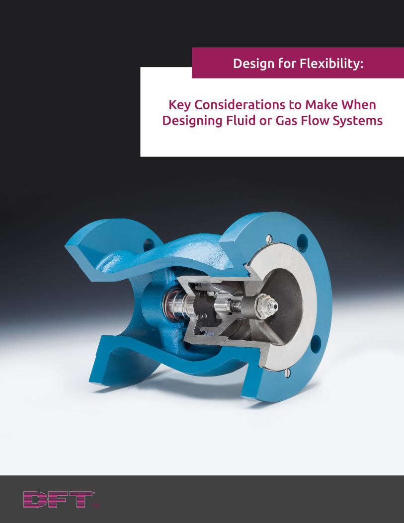
Key Considerations to Make When Designing Fluid or Gas Flow Systems
Design for Flexibility:

DFT Inc. 140 Sheree Blvd. PO Box 566, Exton, PA 19341
toll-free 800-206-4013 fax 610.524.9242 e-mail [email protected] 2
1. The Basics of Check Valve Design .................................................3
2. The Basic Valve Choices
Lift Check Valves ......................................................................4
Swing Check Valves .................................................................5
Ball Check Valves ......................................................................6
Pump Control Valves ...............................................................7
3. Check Valve Selection Criteria .......................................................8
Initial Costs .................................................................................9
Maintenance Costs ...................................................................9
Head Loss and Energy Costs ..................................................10
Non-Slam Characteristics ........................................................11
Fluid Compatibility ...................................................................11
Sealing Ability ............................................................................12
Flow Characteristics .................................................................12
4. Benefits of Design Flexibility .........................................................13
5. Conclusion ...........................................................................................14
Table of Contents
DFT Inc. 140 Sheree Blvd. PO Box 566, Exton, PA 19341
toll-free 800-206-4013 fax 610.524.9242 e-mail [email protected] 3
Check valves, also known as non-return valves, are valves that allow a fluid (either liquid or gas) to flow
through the system in only one direction. Check valves are normally two-port valves, having two openings in
the body. One opening only allows fluids to enter the body, and the other only allows fluids to exit.
Check valves are used in many industrial fluid systems such as those in chemical and power plants, refineries,
oil fields, mines and water/waste water treatment. They are used when multiple media require mixing into
a media stream. Multiple check valves can be installed on each of the individual fluid streams to prevent any
extraneous mixing of those fluids back into the original sources. For example, if a fuel and an oxidizer are to
be mixed, then check valves will normally be used on both the fuel and oxidizer sources to ensure that the
original gas cylinders remain pure and in an undiluted state.
What is a Check Valve?
An essential element in the design of an efficient pumping system is the proper selection of the check valves.
The check valve must, of course, automatically open to allow forward flow and automatically return to its
closed position to prevent a reverse flow when the pump is not in operation. Check valves perform a critical
function in preventing reverse flows of fluids, protecting plant and mechanical equipment from damage.
However, there are a wide variety of different types, and significant differences in performance and duties even
within a single type of valve. We will specifically be looking at the Lift Check, Ball Check, Swing Check and Pump
Control Valves for this comparison.
Another consideration when designing a pumping system is to choose check valves that minimize energy
consumption. Wastewater treatment plants in the United States consume more than 75 billion kWh of energy
annually. The pumping costs to overcome static head and friction loses account for 80% of that alone. Most
of the time the money saved by installing a series of improperly selected check valves may be eclipsed by the
additional pumping costs to run the systems because of this choice.
Unfortunately, every pumping system has the potential to undergo some amount of water hammer or slam.
Water hammer is caused by the sudden stoppage of a reversing flow as it goes through a closing valve. The
stopping of the reverse flow transforms the kinetic energy of a flowing fluid into a pressure shock wave, which
runs back down the pipes. The pressure surge associated with these shock waves can, in the worst case, cause
flanged joints to rupture, or at the very least cause severe noise and vibration in the piping system itself. In
order to minimize these pressure shock waves, a check valve must be selected that closes very quickly once the
pump is shut down and prevents the reversing of the fluid flow.
1 The Basics of Check Valve Design
DFT Inc. 140 Sheree Blvd. PO Box 566, Exton, PA 19341
toll-free 800-206-4013 fax 610.524.9242 e-mail [email protected] 4
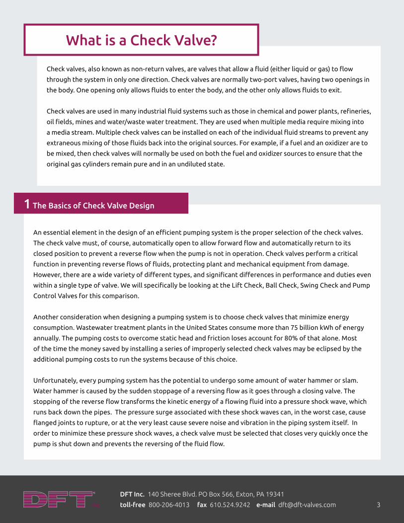
Lift Check Valves – A lift check valve is a simple, automatic and normally cost effective valve. Examples
of these types of valves include piston checks and in-line (silent) check valves and nozzle check valves. These
valves have no external moving parts and are economical to produce and provide very reliable operation.
Generally, these are check valves in which the disc, or main closure mechanism, is lifted off of the valve seat by
the pressure of the inlet fluid. This allows fluid to flow through past the disc and seat and through the valve to
the outlet or downstream end. The motion of the disc is guided in a straight line, so the valve can later reseat
properly. When the upstream fluid pressure diminishes, gravity or an opposing spring, causes the ‘disc’ to move
towards the seat, shutting the valve and stopping the flow.
While in Piston Check Valves the disc or closure mechanism moves at a right angle to the axis of the fluid flow,
in Silent or Axial Flow check valves the disc moves in the same axis as the axis of the piping or fluid flow. When
the flow is initiated, the disc is pushed out of its seat parallel to the direction of flow, and the pressure of the
fluid flow is opposed by a compression spring. The fluid is allowed to flow out and around the disc and into the
nozzle end of the valve, at the outlet end. The shape of this outlet or nozzle end reduces pressure losses within
the valve by reducing turbulence and eddy, or counter flow currents.
When the pump is stopped, the compression spring in the axial flow check valve forces the valve closed prior
to a complete reversal of fluid pressure. This is what provides the silent closure. These valves are also one of
the fastest to close (in about 1/10th of a second). However, because the disc remains in the flow stream, these
types of valves can have a higher head loss, than swing style check valves. The concept of the axial flow check
valves internal design is to provide a hydrodynamic shape that reduces pressure losses. This internal shaping
of the fluid flow area creates a smoother Venturi shaped flow path for the fluid. Axial flow check valves are
commonly made from steel and many other high alloys and are designed for high pressure classes and meet the
rigorous standards of all industrial applications including both nuclear and non-nuclear power plants, refineries,
oil fields, chemical plants and many other applications.
2 The Basic Valve Choices
DFT Inc. 140 Sheree Blvd. PO Box 566, Exton, PA 19341
toll-free 800-206-4013 fax 610.524.9242 e-mail [email protected] 5
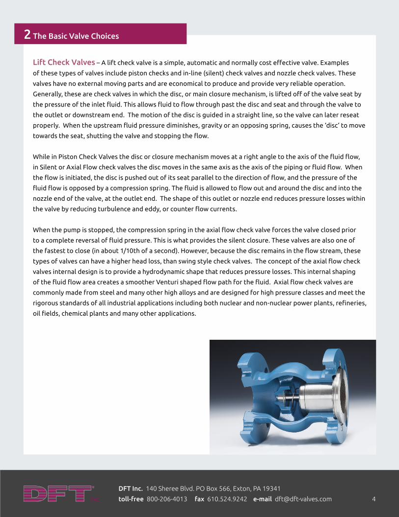
Swing Check Valves – The swing check valve is historically the most common category of check valve used
in piping and pumping systems. They are low cost, readily available and some designs offer a lower head-loss
when open. They are fully automatic, and require no additional power or control signal. However, since they
rely on gravity and usually have no spring of mechanical means of closing the valve, they operate strictly on
the change of flow direction. This means they can only be used in horizontal or vertical “up” pipe lines and are
highly susceptible to water hammer and slamming.
The swing check valve is traditionally a flat disc that pivots or swings within the flow of the fluid. The movable
part swings on a hinge or trunnion, either onto the seat to block reverse flow or off the seat to allow forward
flow. The seat, which is normally integral to the body, is oriented at a slight angle to the axis of the pipe
itself. Great care must be taken when rebuilding a swing check to insure that the disc makes a full contact
on the entire circumference of the seat. One of the results of wearing of the hinge pin is that the disc will
slip downwards over time and no longer make a full 360 degree contact with the seat, resulting in increasing
leakage over time.
Swing check valves are available in many sizes generally starting from 1”. Larger check valves are often
specified as swing check valves. Many accessories exist for swing valves to assist in reducing the probability of
water hammer. These accessories include the addition of weights, and spring assisted closing mechanisms. Oil
and compressed air dampening systems are also available to reduce slam. However, with the addition of any of
these accessories come increases in head-loss and cost of the valve itself.
2 The Basic Valve Choices (cont.)
DFT Inc. 140 Sheree Blvd. PO Box 566, Exton, PA 19341
toll-free 800-206-4013 fax 610.524.9242 e-mail [email protected] 6
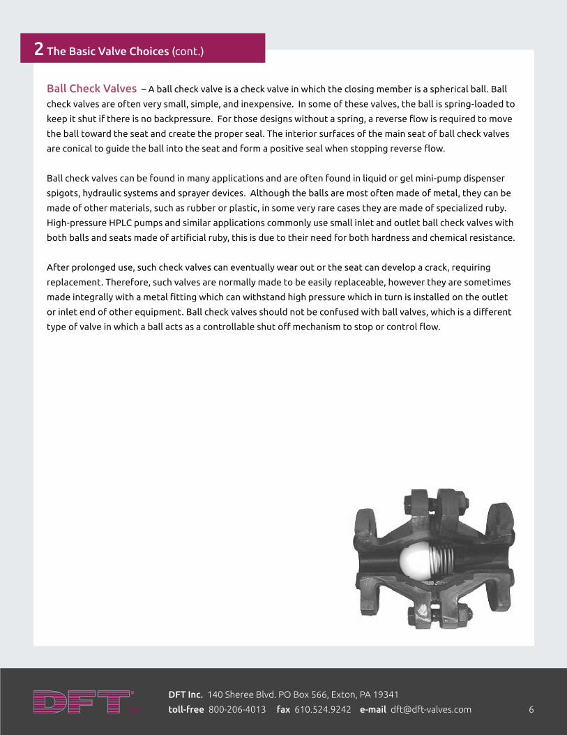
Ball Check Valves – A ball check valve is a check valve in which the closing member is a spherical ball. Ball
check valves are often very small, simple, and inexpensive. In some of these valves, the ball is spring-loaded to
keep it shut if there is no backpressure. For those designs without a spring, a reverse flow is required to move
the ball toward the seat and create the proper seal. The interior surfaces of the main seat of ball check valves
are conical to guide the ball into the seat and form a positive seal when stopping reverse flow.
Ball check valves can be found in many applications and are often found in liquid or gel mini-pump dispenser
spigots, hydraulic systems and sprayer devices. Although the balls are most often made of metal, they can be
made of other materials, such as rubber or plastic, in some very rare cases they are made of specialized ruby.
High-pressure HPLC pumps and similar applications commonly use small inlet and outlet ball check valves with
both balls and seats made of artificial ruby, this is due to their need for both hardness and chemical resistance.
After prolonged use, such check valves can eventually wear out or the seat can develop a crack, requiring
replacement. Therefore, such valves are normally made to be easily replaceable, however they are sometimes
made integrally with a metal fitting which can withstand high pressure which in turn is installed on the outlet
or inlet end of other equipment. Ball check valves should not be confused with ball valves, which is a different
type of valve in which a ball acts as a controllable shut off mechanism to stop or control flow.
2 The Basic Valve Choices (cont.)
DFT Inc. 140 Sheree Blvd. PO Box 566, Exton, PA 19341
toll-free 800-206-4013 fax 610.524.9242 e-mail [email protected] 7
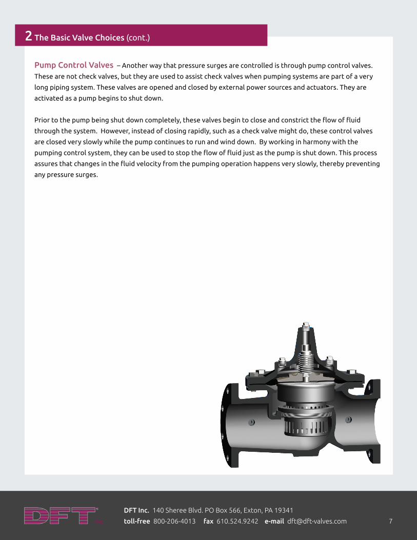
Pump Control Valves – Another way that pressure surges are controlled is through pump control valves.
These are not check valves, but they are used to assist check valves when pumping systems are part of a very
long piping system. These valves are opened and closed by external power sources and actuators. They are
activated as a pump begins to shut down.
Prior to the pump being shut down completely, these valves begin to close and constrict the flow of fluid
through the system. However, instead of closing rapidly, such as a check valve might do, these control valves
are closed very slowly while the pump continues to run and wind down. By working in harmony with the
pumping control system, they can be used to stop the flow of fluid just as the pump is shut down. This process
assures that changes in the fluid velocity from the pumping operation happens very slowly, thereby preventing
any pressure surges.
2 The Basic Valve Choices (cont.)
DFT Inc. 140 Sheree Blvd. PO Box 566, Exton, PA 19341
toll-free 800-206-4013 fax 610.524.9242 e-mail [email protected] 8
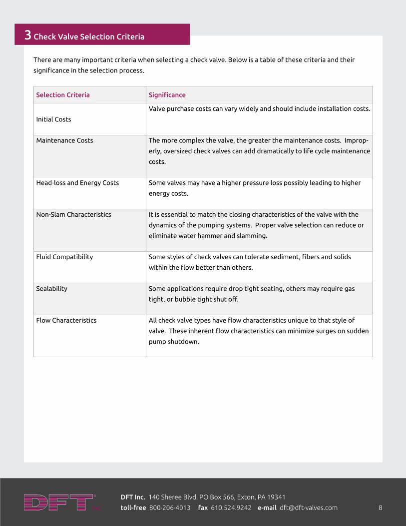
There are many important criteria when selecting a check valve. Below is a table of these criteria and their
significance in the selection process.
Selection Criteria Significance
Initial Costs
Valve purchase costs can vary widely and should include installation costs.
Maintenance Costs The more complex the valve, the greater the maintenance costs. Improp-
erly, oversized check valves can add dramatically to life cycle maintenance
costs.
Head-loss and Energy Costs Some valves may have a higher pressure loss possibly leading to higher
energy costs.
Non-Slam Characteristics It is essential to match the closing characteristics of the valve with the
dynamics of the pumping systems. Proper valve selection can reduce or
eliminate water hammer and slamming.
Fluid Compatibility Some styles of check valves can tolerate sediment, fibers and solids
within the flow better than others.
Sealability Some applications require drop tight seating, others may require gas
tight, or bubble tight shut off.
Flow Characteristics All check valve types have flow characteristics unique to that style of
valve. These inherent flow characteristics can minimize surges on sudden
pump shutdown.
3 Check Valve Selection Criteria
DFT Inc. 140 Sheree Blvd. PO Box 566, Exton, PA 19341
toll-free 800-206-4013 fax 610.524.9242 e-mail [email protected] 9
Initial Costs – The purchase cost of various check valves vary widely based on their level of quality or the
number of accessories involved. However, the purchase cost is only one aspect of the total initial cost. The
installation cost of the valves can actually be more significant than the purchase cost of the unit. In addition,
all valves, including check valves, require a minimum of 5 times the nominal diameter as lengths of straight pipe
run on the inlet and outlet ends in order to minimize turbulence going into the valve and to avoid premature
wear or failure of the valves and the system.
The initial costs can also include additional structural support for the system if the valve design increases the
unsupported weight of the piping. There may also be considerations for new (or upgraded) electrical switching
or actuating systems. In many cases, the cost of the check valve itself is actually only a small percentage of the
total installed cost.
Maintenance Costs – Check valves can be complicated or quite simple in design. A simple lift or swing style
check valve can offer decades of service before requiring maintenance (>50,000 cycles). Periodic maintenance
on a check valve usually only requires that the operator listen to the valve when the system is not pumping to
detect any evidence of leakage, such as hissing or the sound of water running. During the operation of the
system, there should not be any tapping noises heard within the valve, this would indicate an oversized valve
condition, which could result in increasing leakage and eventual valve failure.
Depending on the type, check valve maintenance can vary significantly. Swing check valves with external
levers and weights have seals that need to be checked regularly and repacked to prevent external leakage and
pressure loss. If these seals are done improperly, they can reduce the lifespan of the valves and also result in
increased in water hammer. A properly sized and maintained check valves can be completely self-contained
and require very little regular maintenance. If leakage is detected, many check valves can be repaired in line
without removal, during a planned outage.
Pump control valves, on the other hand, can require significantly more maintenance than a properly designed
check valves, and may not be able to react quickly enough to sudden pump shutdown. Regular maintenance
on these types of control valves involves servicing the actuators, cleaning the air filters and solenoids, and
monitoring and adjusting the controls.
Due to the complexity of the controls, these types of systems require specialized personnel to be trained to
run and maintain the systems. Some manufacturers and many valve service and repair companies offer service
contracts in order to increase system reliability and assure dependable operation.
3 Check Valve Selection Criteria (cont.)

DFT Inc. 140 Sheree Blvd. PO Box 566, Exton, PA 19341
toll-free 800-206-4013 fax 610.524.9242 e-mail [email protected] 10
Head Loss and Energy Costs – Static head is the difference in elevation between the fluid source and
the highest point of system. Static head would be a constant for the system unless there was a change in
the piping geometry and has to be overcome every time the pump is in operation. The frictional head loss is
another energy loss factor in system design and is influenced by the roughness of the pipe as well as by local
flow disturbances such as fittings and valves. The geometry of the check valve body and the design of the
closure member are important in reducing the head-loss associated with the valve. The outlet end of the check
valve must be designed to minimize pressure losses due to flow of the fluid within the valve itself. All pumping
systems along with the associated distribution system of piping and valves will have inherent frictional head loss.
Valve body geometry must be chosen properly to fit within the allowable space within the piping structure.
Valve bodies and laying lengths vary greatly among the many check valve styles that are available. The range
of laying lengths, also called take out length or face to face, can be quite large. Wafer style valve bodies have
the shortest laying lengths and valves of this construction conform to either MSS SP 126, API 594 or EN 558
series 51 standards for this dimension. Other, longer face to face standards exist, which are normally applied to
flanged end or butt weld end valves. ASTM B16.10 and EN 558 series 21 are the face to face standards normally
applied to these types of valves. This tradeoff between check valve style and the piping system structure itself
must be factored into the choice of the most suitablbe check valve type.
Many valves can restrict the flow of fluid, increasing head-loss through turbulence and friction. One must also
factor in the design of the closure mechanism and its impact on reduce head-loss. The lowest head-loss is
achieved when the disc swings or rotates fully out of the flow path. However, this situation is not possible in all
check valve designs. In those cases, the closure member can be contoured or shaped to allow for better fluid
flow characteristics and lower pressure losses.
Lastly, head-loss is also a function of fluid velocity within the system. Frictional loss is proportional to the
velocity squared. That means that a doubling of line velocity increases the head loss of the system by a factor
of four. Since the head-loss is a function of fluid velocity, the overall cost of energy consumption versus pipe
costs must also be evaluated. Optimizing pipe-size and velocity can provide cost savings in both installation and
annual operating costs, but that may be at the expense of oversizing check valves, which can adversely affect
maintenance costs and total cost of ownership.
3 Check Valve Selection Criteria (cont.)
DFT Inc. 140 Sheree Blvd. PO Box 566, Exton, PA 19341
toll-free 800-206-4013 fax 610.524.9242 e-mail [email protected] 11
Non-Slam Characteristics – All piping systems transporting liquids will be impacted by water hammer that
results from sudden pump shutdown or the sudden opening or closing of valves within the system. Many check
valve styles allow for some reverse velocity before the disc closes against the seat. Therefore it is essential to
match the closing characteristic of the valve with the dynamics of the pumping system. In order to reduce check
valve slam it is essential that the valve close as quickly as possible as well as before fluid flow reverses. There are
four items that influence the non-slam characteristics of a particular style of check valve - disc location in the
full open position, length of stroke to close, presence of some closure mechanism either internal or external to
the valve and orientation of the valve and piping. Discs in check valves are often times located as far out of the
flow as possible in order to reduce head-loss. However, as many of these valve’s must be sensitive to the flow
direction and velocity in order to close, the further out of the flow they sit, the more time is required for the
valve to respond to a slowing or reversing flow and hence, it will be slower to close. The length of stroke is one
aspect of the design that causes a tradeoff between slam reducing characteristics and head-loss. In summary,
the longer the stroke of the valve, the lower the head-loss, but a longer stroke requires more time to close.
The orientation of the valve can also affect the slam reducing characteristics of the valve. This is more noticeable
in vertical installations than it is in horizontal installations. A vertically installed check valve is usually placed in
the system because there was no better place to install it. If the flow is going vertically down, then static head
must be added to the desired cracking pressure for the valve to open. Systems with high static heads usually
have an increased probability for higher reversing flows due to gravity. For these types of systems, it is good to
have short linear strokes and a spring assisted closing mechanism to cope better with the flow as the pump shuts
down to avoid reversing flow. Again, higher cracking pressure check valves will increase the head-loss in the
active system.
Fluid Compatibility – When selecting a check where there is a known concentration of suspended solids
and/or fibers, care must be taken to insure that the internal design of the valve will not cause clogging or
fouling of the valve to occur. Whereas all the previously mentioned check valves can handle clean fluids, as
well as treated wastewater with no solids, only certain check valves can handle fluids with concentrations of
suspended solids that exceed 3-4%. The factors to consider when working with suspended solids include, but
are not limited to:
• The seating surfaces of the valve and how they may resist abrasion from the solids
• The mechanics of the valve and how the internal passages may collect and trapsolid materials
• The straightness of the valve internal flow path configuration: voids will collect deposits of solid materials
while changes in flow direction may cause accelerated wear of the valve body
These concepts may directly eliminate many valve types from consideration.
3 Check Valve Selection Criteria (cont.)

DFT Inc. 140 Sheree Blvd. PO Box 566, Exton, PA 19341
toll-free 800-206-4013 fax 610.524.9242 e-mail [email protected] 12
Sealing Ability – In general, there are two types of sealing materials - resilient or soft seat seals and metal-
to-metal seat seals.
• Resilient Seals
The goal of the resilient seat is to provide a long lasting and leak-tight seal. They are composed of engineered
elastomers that can withstand various types of chemicals and temperatures. Some of these types of seals are
highly resistant to abrasion and can seal against uneven surfaces. However, these types of valves are mainly
used for lower pressure and lower systems. Although elastomeric and polymeric seals have been proven useful
at pressures at 500 pounds per square inch gauge (psig), their reliability becomes may decrease at higher
pressures.
• Metal to Metal
As pressures and temperatures increase in a piping system, metal-to-metal seals begin to become more reliable
than resilient seals. Above 500 psig, a metal-to-metal seal is becomes more and more attractive. The metallic
surfaces of these valves have to be able to handle the higher contact forces associated with these higher
pressures while providing tighter and tighter sealing as pressures increase. Normally a metal seated check
valve will show increasing leakage up to about 250 psi, then as pressures continue to increase, leakage rates will
decrease.
With resilient seals working below 500 psig and metal-to-metal seals becoming more and more effective above
250 psig, there is a middle range, overlap of pressures. Between 250 and 500 psig, either type of seal might
be equally effective. In this middle range of pressures, the various seal options should be reviewed with the
manufacturer and combined with field experience for the intended application prior to final selection.
Flow Characteristics – While a check valve may prevent slam in a local piping system, even the fastest
closing check valve will not protect a long pipeline from the pressure surges created during a pump starts up
or shuts down suddenly. In order to understand the dynamics of a piping system there must be a complete
analysis of its entire flow characteristics. Water hammer is not the only source of pressure surges in a long
pipeline, small pressure spikes, caused from the change in fluid velocity during start up and shut down, are
amplified to greater degrees along longer and longer pipelines.
This is why it is critical to analyze the system as a whole and not just the valve head-loss at each individual check
valve. The desired result of this analysis is to choose a system consisting of pump control valves and check
valves that work together so that they gradually, and uniformly, alter the flow rate in order to prevent water
hammer and pressure surges. This might require systems to use a variety of check valves, including unique or
customized designs.
3 Check Valve Selection Criteria (cont.)
DFT Inc. 140 Sheree Blvd. PO Box 566, Exton, PA 19341
toll-free 800-206-4013 fax 610.524.9242 e-mail [email protected] 13
Design flexibility means looking into variations in through-life maintenance requirements and life cycle costs to
determine the optimal choice for the system. These choices can amount to millions of dollars over a typical life
of many large piping systems. The check valve is a vital component of any pipeline system; its primary duty is to
prevent reversing flow of a fluid by closing as quickly as possible when the flow changes in a pipeline.
This is extremely critical in pumping systems, where return flows would damage the equipment by driving them
in reverse, resulting in unnecessary shutdown and maintenance of the system.
Ideally, a check valve will allow flow only in the desired direction with as little resistance or pressure loss as
possible. This will minimize the pressure losses within the system and therefore energy consumption required.
Proper check valve selection also influences significantly on the life cycle cost of the valve and the system as a
whole.
A number of the very latest advanced tools have been utilized to optimize the design of new non-Slam check
valves. These tools combine computer flow modeling (computational fluid dynamics, CFD), as well as computer
stress modeling (finite element analysis, FEA), and flow testing (using rapid prototype development and flow
loop testing), both to improve dynamic performance and reduce hydraulic losses within a pumping system.
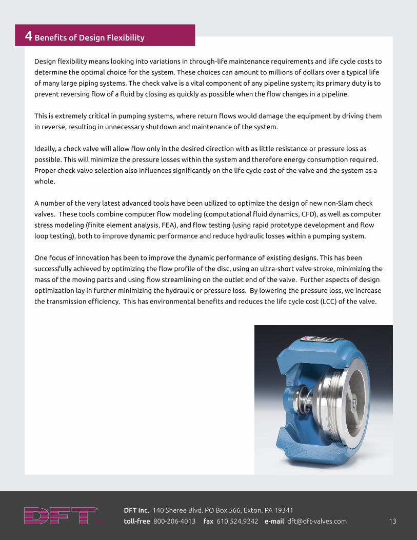
One focus of innovation has been to improve the dynamic performance of existing designs. This has been
successfully achieved by optimizing the flow profile of the disc, using an ultra-short valve stroke, minimizing the
mass of the moving parts and using flow streamlining on the outlet end of the valve. Further aspects of design
optimization lay in further minimizing the hydraulic or pressure loss. By lowering the pressure loss, we increase
the transmission efficiency. This has environmental benefits and reduces the life cycle cost (LCC) of the valve.
4 Benefits of Design Flexibility

DFT Inc. 140 Sheree Blvd. PO Box 566, Exton, PA 19341
toll-free 800-206-4013 fax 610.524.9242 e-mail [email protected] 14
When designing a pumping system it is important to look at the system as a whole. Each check valve or pump
control affects, and is affected by, the other components upstream and downstream in the pipe line. With the
increased power of computer modeling systems, complex systems have become easier to model and analyze
through CFD and FEA. These types of analyses have led to improved valve and system performance resulting in
lowered maintenance and operating costs.
Proper analysis of an entire system now allows the operator to compare and analyze various check valves and
pump controls within the same system to determine the optimum system design. Theoretical analysis of a
system must also be combined with the expert knowledge of how a system works in a more practical sense, as
well as an economic sense.
A theoretically optimal system is a great starting point, but it must also be tempered with the knowledge of
experience in the field. The valves chosen might not be the least expensive valves, or ones that are easiest to
install, but they always need to be the ones that can best handle the job. Properly selected valves will reduce
the full cost of ownership of the system, and provide the desired economics that the operators are looking for.
5 Conclusion