design for ecsl-dp model-integrated computing (mic) is an infrastructure for model-based design of...
TRANSCRIPT

Institute for Software Integrated Systems Vanderbilt University Nashville Tennessee, 37203
TECHNICAL REPORT TR#: ISIS-05-605 Title: A Semantic Unit for Timed Automata Based Modeling Languages Author: Kai Chen, Janos Sztipanovits, Sherif Abdelwahed
1
Abstract
Model-Integrated Computing (MIC) is an infrastructure for model-based design of real-time and embedded software and systems. MIC places strong emphasis on the use of domain-specific modeling languages (DSMLs) and model transformations in design flows. Building on our earlier work on transformational specification of semantics for DSMLs, the paper proposes a “semantic unit” - a common semantic model - for timed automata behavior. The semantic unit is defined using Abstract State Machine (ASM) formalism. We show that the precise semantics of a wide range of timed automata based modeling languages (TAMLs) can be defined through specifying model transformations between a domain-specific TAML and the semantic unit. The proposed method that we call semantic anchoring is demonstrated by developing the transformation rules from the UPPAAL and IF languages to the semantic unit.
2
Table of Contents 1. Introduction 4
2. Overview of Semantic Anchoring 6
3. A Semantic Unit for Timed Automata Based Modeling Languages 8 3.1 Overview of TASU 8 3.2 Abstract Data Model 10 3.3 Operational Semantics 12 3.4 Modeling language specification for TASU 17
4. Semantic Anchoring to TASU 20 4.1 Semantic Anchoring for the UPPAAL Language
4.1.1 Location invariants 20 4.1.2 Urgent/Committed locations 20 4.1.3 Urgent synchronizations 21
4.2 Semantic Anchoring for the IF Language 21 4.2.1 Lazy/Delayable/Eager transitions 22 4.2.2 Unstable locations 22 4.2.3 Asynchronous signal routes 22
5. Conclusions and Future Work 25
References 26
Appendix: Metamodels for Graphical Languages 28
3

1. Introduction Emerging frameworks for model-based design such as Model-Integrated Computing (MIC) [1], Model Driven Architecture (MDA) [2] and Model Driven Design (MDD) [3] share the common vision of raising the level of abstraction in system and software design by placing models that are formal and manipulable in the focus of the design process. In all approaches to model-based design, modeling languages play major roles that fall into the following three categories:
1. Unified (or universal) modeling languages, such as UML [4] and Modelica [5], are designed with goals similar to programming languages; they optimized to be broad and intend to offer the advantage for adopters to remain in a single language framework independently from the domain and system category they concerned with. Necessarily, the core language constructs are tailored more toward an underlying technology (e.g. object modeling) rather then to a particular domain - even if extension mechanisms such as UML profiling allow some form of customizability.
2. Interchange languages, such as the Hybrid System Interchange Format (HSIF) [6], are designed for sharing models across analysis tools (hybrid system analysis). Interchange languages are optimized for providing specific quantitative analysis capabilities in design flows via facilitating the integration of a group of tools. Accordingly, they are optimized to cover concepts related to an analysis technology.
3. Domain-specific modeling languages (DSMLs) [8] are tailored to the particular concepts, constraints and assumptions of application domains. They are optimized to be focused: the modeling language should offer the simplest possible formulation that is still sufficient for the modeling tasks. Model-based design frameworks that aggressively use DSMLs, need to support the composition of modeling languages. For example, the MIC infrastructure uses abstract syntax metamodeling and meta-programmable tool suites [12] for the rapid construction of DSMLs with well defined syntax and semantics.
While abstract syntax metamodeling has been a very important step in model-based design and is used not only in MIC but also in various MDA and MDD frameworks, such as Eclipse [9] and Software Factories [3], explicit and formal specification of semantics has been an unsolved problem whose significance not even recognized. For instance, the SPT profile [7] (UML Profile for Schedulability, Performance and Time) does not have precisely defined semantics [24], which creates possibility for semantic mismatch between design models and modeling languages of analysis tools. This is particularly problematic in safety critical real-time and embedded systems domain, where semantic ambiguities may produce conflicting results across different tools.
There has been much effort in the research community to define semantics of modeling languages by means of informal mathematical text [6] or using formal mathematical notations [10]. In either case, precise semantics specification for DSMLs remains a challenge. To solve this problem, in our former paper [11], we proposed and demonstrated a method and tool infrastructure for semantic anchoring that facilitates the transformational specification of DSML semantics. The proposed semantic anchoring infrastructure includes a set of well-defined “semantic units” that capture the operational semantics of basic dynamic behaviors and models of computations using Abstract State Machines [15] as an underlying formal framework. The semantics of a DSML is defined by specifying the transformation between the abstract syntax metamodel of the DSML and that of the semantic unit.
In this report we build on our earlier result and develop a Semantic Unit for modeling languages that use timed automata semantics. Timed Automata Modeling Languages are widely used for modeling and analysis of real-time and embedded systems. Therefore, we believe that the work can contribute to the establishment of precise semantics for UML-TPC. The proposed Timed Automata Semantic Unit (TASU) is priority-oriented. Both an abstract mathematical definition and formal specification of TASU using the
4
Abstract State Machine Language (AsmL) [17] are presented in this paper. We also show examples for the semantic anchoring process by presenting anchoring rules for the UPPAAL [21] and IF [22] languages.
This report consists of the following sections: Section 2 introduces the concepts of semantic units and semantic anchoring. We specify TASU in Section 3. The semantic anchoring rules from the UPPAAL and IF languages to TASU are illustrated in Section 4. Section 5 is our conclusion and future work. An Appendix introduces the metamodeling concepts used in GME, which are employed in the TASU metamodels.
5

2. Overview of Semantic Anchoring A DSML can be formally defined as a 5-tuple L = <A, C, S, MS, MC> consisting of abstract syntax (A), concrete syntax (C), syntactic mapping (MC), semantic domain (S) and semantic mapping (MS) [25]. The abstract syntax A defines the language concepts, their relationships, and well-formedness rules available in the language. The concrete syntax C defines the specific notations used to express models, which may be graphical, textual, or mixed. The syntactic mapping, MC: C → A, assigns syntactic constructs to elements in the abstract syntax.
The DSML semantics are defined in two parts: a semantic domain S and a semantic mapping MS: A → S. The semantic domain S is usually defined in some formal, mathematical framework, in terms of which the meaning of the models is explained. The semantic mapping relates syntactic concepts to those of the semantic domain.
Although DSMLs use many different modeling and model composition concepts and notations for accommodating needs of domains and user communities, semantic domains for expressing fundamental types of dynamic behaviors are more limited. Broad categories of component behaviors can be represented by behavioral abstractions, such as Finite State Machine, Timed Automaton and Hybrid Automaton. This observation led us to propose a semantic anchoring infrastructure for defining behavioral semantics for DSMLs. The development of a semantic anchoring infrastructure includes the following tasks [11]:
1. Defining a set of modeling languages {Li} for the basic behavioral abstractions and developing the precise specifications for all components of Li = <Ci, Ai, Si, MSi, MCi>. We use the term “semantic units” to describe these basic modeling languages.
2. Defining the behavioral semantics of an arbitrary L = <C, A, S, MS, MC> modeling language by specifying the MA : A → Ai mapping. The MS : A → S semantic mapping of L is defined by the MS = MSi ○ MA composition, which indicates that the semantics of L is anchored to the Si semantic domain of the Li modeling language.
Figure 1: Tool suite for DSML design through semantic anchoring
Figure 1 shows our tool suite to facilitate DSML design through semantic anchoring. It comprises (1) the ASM-based common semantic framework for specifying semantic units and (2) the MIC modeling (GME) and model transformation (GReAT) tool suites that support the specification of transformation between the DSML metamodels and the Abstract Data Models used in the semantic units. In the rest of this section, we give a short introduction to the related tools. Readers can refer [11, 14] for detailed knowledge about the semantic anchoring tool suite.
We selected Abstract State Machine (ASM) [15], formerly called Evolving Algebras [16], as a formal framework for the specification of semantic units. General forms of behavioral semantics can be encoded
6

as (and simulated by) an abstract state machine [15]. AsmL [18], developed by Microsoft Research, provides specification language simulator, test-case generation and model checking tools for ASMs.
The Generic Modeling Environment (GME) tool suite [12] is employed for defining the abstract syntax metamodels for DSMLs using the UML/OCL [4, 18] – based MetaGME as the metamodeling language1. The MA : A → Ai semantic anchoring of L to Li is defined by model transformation rules expressed in the UTM (Unified Transformation Model) language of the GReAT tool suite [13]. In UMT, model transformations are expressed as graph transformations that can be executed (both in interpreted and compiled form) by the GReAT engine. In summary, semantic anchoring specifies DSML semantics by the operational semantics of selected semantic units (defined in AsmL) and by the transformation rules (defined in UTM). The integrated tool suite [14] enables that domain models defined in a DSML are simulated according to their “reference semantics” by automatically translating them into AsmL data models using the transformation rules.
1 In the following discussion the knowledge of the meta-modeling approach used in GME is assumed. The
provides a brief summary, while the GME software distribution contains the precise documentation as well as a detailed tutorial. Appendix: Metamodels for Graphical Languages
7
3. A Semantic Unit for Timed Automata Based Modeling Languages
Timed Automata [19] were proposed for modeling the behavior of real-time systems over time. Several analysis tools for real time systems, such as UPPAAL [21], IF toolset [22] and Kronos [23], were developed based on this modeling approach. They use timed automata based modeling languages (TAMLs) that have tool dependent differences in their approach to express communication among concurrent components and action (transition) priorities. The similarities and differences in the syntax and semantics of varied TAMLs may confuse designers and lead to mistakes. There are plenty of examples for language constructs that may appear similar while they express essentially different semantics and language constructs that appear different but have essentially the same semantics.
In this section, we propose a priority-oriented Timed Automata Semantic Unit (TASU) as a common semantic model for TAMLs. We propose that semantics of different TAMLs are defined by specifying the transformation between them and TASU. The explicit representation of transformation rules, the formal operational semantics specification of TASU and the behavioral simulation support allow designers understanding and comparing languages with different timed automata semantics and help the integration of different analysis tools in design flows.
3.1 Overview of TASU A timed automaton is a finite-state automaton equipped with a finite set of clock variables [19]. In this original specification a strong synchrony assumption is adopted for time progress, which means that all clock variables progress at the same rate. Transitions are executed instantly and time progresses only when an automaton is in a location. Constraints on clock variables can be used as conditions for enabling transitions. Transitions can be associated with actions that reset clock variables.
In order to facilitate modeling concurrent real-time systems, many TAMLs (e.g. UPPAAL and IF) extend the original timed automata with parallel composition to specify networks of automata. The supported communication mechanisms vary across tools. In general, such communication can be categorized into three categories: shared variables, synchronous and asynchronous communication. In most cases, asynchronous communication can be modeled by synchronous communication plus automata representing buffers. To keep balance between the semantic expressivity and complexity, our proposed semantic unit directly supports communication only through shared variables and synchronization. If needed, asynchronous communication is specified via mapping to the synchronous communication through model transformation.
Transition priority is a very useful concept for reducing non-determinism in models and for modeling interrupts or preemption in real-time systems. Also, dynamic priorities match well with practical implementations of real-time systems. Priority information is implicitly expressed in certain language constructs of a TAML. For instance, an urgent location in UPPAAL indicates that transitions out from this location have higher priority than that of time progress [21]. The priority of a transition is, in general, time dependent. For example, a delayable transition in IF semantically implies that the priority of this transition jumps to a higher value than that of time progress when the enabling condition of this transition is about to be violated by time progress [22].
Although priority hierarchies of TAMLs are tool-dependent, they have many common features. In order to compare and integrate models from varied TAMLs, we need to establish a generic priority scheme that is capable of capturing all these priority hierarchies. A fundamental common feature is that all these tool-defined priority schemes are built with respect to the time progress priority, which enables modeling urgency of actions in real-time systems. An urgent action in real-time systems is modeled as a transition having higher priority than that of time progress. In some TAMLs, urgent transitions are additionally
8

divided into two groups: normal urgent transitions and most urgent transitions. A most urgent transition prohibits the execution of any other transitions as well as time progress. This enables modeling of an atomic action that is composed of a sequence of sub-actions. In TASU, the priority hierarchy has three layers: the bottom priority (the time progress priority), the top priority (the priority to model atomic actions), and the urgent priority, which has a series of urgency degrees. We will show that this priority hierarchy is capable of expressing varied priority hierarchies defined by TAMLs.
In the proposed TASU, a real-time system contains a set of concurrent components. Each component is modeled by a timed automaton. Components communicate among each other through shared variables and synchronization. The priority of an action can be dynamically updated with respect to time progress. Enabled actions with higher priorities will block actions with lower priorities. Non-determinism is supported by allowing multiple enabled actions with the same priority. Based on the timed automata model defined in [20], we present an abstract mathematical definition for a timed automaton in the semantic unit.
Given a finite set of variables V, a valuation for the variables is a function ν∈ℜV that assigns a value for each variable from the domain of real numbers. If |V| = n the valuation can be represented as the vector
nv ℜ∈ . We denote the valuation for an element i∈ N as vi. A linear expression )(vφ over V can be
expressed as where (integers) and∑ ii va Ζ∈ia Vvi ∈ . A linear constraint γ is of the form )(νφ op c where
)(vφ is a linear expression over V, op ∈ {=, <, ≤, >, ≥} and c ∈ Ζ. We denote the set of linear constraints
over the set of variables V as LC(V). A linear assignment over V is defined as cv +A , where A is an matrix with coefficients from Z and nn× c is a vector of nZ . We denotes a set of linear assignment over the set of variable V as LA(V). The set of simple assignment SA(V) corresponding to the case when all entries of A are 0 and 0≥c .
A timed automaton is defined over a set C of resetable clocks and a set V of integer variables. A timed automaton in the semantic unit is a 7-tuple iElLVC Pr,,,,,, 0Σ where:
• C is a finite set of n clock variables,
• V is a finite set of integer-valued variables,
• ∑ is a finite set of symbols defining the system events,
• L is a nonempty set of locations,
• is the initial location, Ll ∈0
• LVCVCLE ×∪×∪×∑×⊆ )()()( LASALC is a set of edges. A edge ll ′,,,,, γβϕα represents a transition from location l to location l’ on symbol α. ϕ is a guard over clock and integer variables. β represents simple assignment for clock variables and γ is linear assignment over integer variables,
• is a map that assigns to each edge its priority, which is a non-negative integer value, with respect to a give clock evaluation , so that is the priority of edge e at clock value v.
+→× NREi n:PrnRv∈ ),(Pr vei
A state of the timed automaton is defined as , where ),,( vcl Ll ∈ , c, v are valuation of the clock C and integer V variables, respectively. The set of all state is denoted S. The step relation denotes a jump transition which is a discrete and instantaneous transition that changes the location of the automaton as well as the assignment of the integer variables and clocks. The step relation denotes a time transition
⎯→⎯α
⎯→⎯t
9

that advances all clock variables at the same value. A time transition may affect the priority of edges through the function Pri. The priority of a time transition is assumed a constant value, zero.
The semantics of a timed automaton model iElLVCM Pr,,,,,, 0Σ= in TASU is given as a transition system where S is the set of states, s0 is the initial state where c0 = 0, and the step relation → is the union of the jump transition:
),,( 0 →= sSTM
• iff ),,(),,( vclvcl ′′′⎯→⎯α Elle ∈=∃ ',,,,, γβϕα such that o )()(),( vvcctruevc γβϕ =′∧=′∧= , and o Elle ∈′′′′′=′∀ ,,,,, γβϕα , ),(Pr),(Pr),( ceiceitruevc ′≥⇒=′ϕ .
and time transition: • iff ),,(),,( vtclvcl t +⎯→⎯
Elle ∈=∀ ',,,,, γβϕα and tt ≤≤∀ '0 , 0),(Pr),( =′+⇒=′+ tceitruevtcϕ .
A run of the timed automata is a finite or infinite sequence of alternating jump and time transition of TM : . 4
23
22
11
10 sssss tt ⎯→⎯⎯→⎯⎯→⎯⎯→⎯= ααρ
The operational semantics for TASU is specified as a Control State ASM [15]. The specification includes three parts: an Abstract Data Model, Operations and Transition Rules. In the ASM formulation, the Abstract Data Model captures the abstract syntax of a modeling language defined for TASU. The Operations and Transition Rules form a model interpreter that specifies the operational semantics. An instance of the Abstract Data Model (we will refer to it as Date Model), Operations and the Transition Rules form an ASM that specifies the model semantics. We document the specification in AsmL for the sake of readability. Because of page limitation, we present only a part of the specification together with short explanations. For a detailed exposure to the AsmL specification, please refer to [14].
3.2 Abstract Data Model We choose to define the Abstract Data Model for TASU by using AsmL classes [17]. The Clock defines a type for clock variables. The variable field time represents the logical time of a clock variable. All clock variables progress at the same rate. For the purpose of model simulation, we introduce an AsmL constant CLOCKUNIT to set the granularity of time progress. A system might define a set of global clocks and each component might define its own local clocks. The globalClocks is an AsmL set containing all global clocks. Note that the set globalClocks is empty in the specification of the Abstract Data Model. Elements of this set are model-dependent and will be specified in instances of the Abstract Data Model (in the Data Models). When the Boolean variable TimeBlocked is set to true, the system explicitly blocks time progress.
class Clock
var time as Double = 0
const CLOCKUNIT as Double
var globalClocks as Set of Clock = {}
var TimeBlocked as Boolean = false
Location and Transition are defined as first-class types. The constant fields blockTime and setPrior in Transition indicate whether this transition is a special transition to block time progress or to set the priority of the owner automaton to the top priority. If any automaton is in the top priority, enabled transitions in all other automata as well as time progress will be prohibited. Note: these two special transition types are adopted for software implementation convenience. They are also denoted as edges whose source and destination locations are the same. (See further explanation in the operational semantics specification.) A transition can participate in a synchronous communication in one of two roles: SEND and RECEIVE.
10

class Location
const id as String
const initial as Boolean
const outTransitions as Set of Transition
class Transition
const id as String
const blockTime as Boolean
const setPrior as Boolean
const dstLocationID as String
enum SYNROLE
SEND
RECEIVE
The class SignalChannel captures the synchronous communication among automata. The variable field senders and receivers record a set of signal senders and receivers, respectively. The Boolean field broadcast indicates whether the signal channel is a broadcasting channel. In a broadcasting channel, a sender publishes events without waiting for receivers and the event will be broadcasted to all receivers that are waiting for it. The event will be lost, if there are no receivers that are waiting for it. A non-broadcasting channel is enabled to fire when there are at least one sender and one receiver that are waiting. Only one sender and one receiver can take part in a synchronization communication and a synchronization pair is chosen non-deterministically when several combinations are enabled.
class SignalChannel
const id as String
const broadcast as Boolean
var senders as Set of
(TimedAutomaton, Transition) = {}
var receivers as Set of
(TimedAutomaton, Transition) = {}
The abstract class TimedAutomaton defines the base structure for a timed automaton. The variable field currentLocation refers to the current location of an automaton. Initially, it refers to the AsmL null value. The AsmL construct Location? indicates that the value of this field may refer to either a Location instance or to the null value. When an automaton is in the top priority layer, its prior field is set to true.
The TimedAutomaton class also holds a set of read-only abstract properties and abstract methods. These abstract properties define an abstract data structure that captures the tuple structure of an automaton. For example, the abstract property syns is a map whose domain consists of transitions that require synchronization. If t is a transition in this domain, then syns(t) is a 2-tuple whose first element refers to the corresponding signal channel and whose second element indicates whether t acts as a sender or a receiver. The abstract method TimeGuard(t) and DataGuard(t) return a Boolean-valued expression of time conditions and data conditions that are attached to the transition t, respectively. The abstract method DoAction(t) executes actions attached to a transition t. The abstract method Priority(t) returns the priority of a transition. Since the priority value of a transition might be dynamically updated, Priority(t) returns either an integer value or an integer-valued expression. All these abstract members of TimedAutomaton are model-dependent specifications for the semantic unit and will be further specified by a concrete automaton template.
11

abstract class TimedAutomaton
const id as String
var currentLocation as Location? = null
var prior as Boolean = false
abstract property locations as Set of Location
get
abstract property transitions as Set of Transition
get
abstract property localClocks as Set of Clock
get
abstract property syns as Map of
<Transition, (SignalChannel, SYNROLE)>
get
abstract TimeGuard (t as Transition) as Boolean
abstract DataGuard (t as Transition) as Boolean
abstract DoAction (t as Transition)
abstract Priority (t as Transition) as Integer
The AsmL class RTSystem captures the top-level structure of a real-time system. The components field holds concurrent components contained in the system. Each component is an instance of a concrete automaton template. These components communicate through a set of signal channels, which are recorded in the field signalChannels.
class RTSystem
const components as Set of TimedAutomaton
const signalChannels as Set of SignalChannel
3.3 Operational Semantics We are now ready to specify the operational semantics for TASU as AsmL Operations and Transition Rules, which interpreter the Abstract Data Model defined above. The specifications start from the top-level system, and proceed toward the lower levels.
An active RTSystem instance executes enabled transitions or advances time. The operational rule Run of RTSystem specifies the top-level system operations as a set of updates. (Note that the AsmL keyword step introduces a set of operations that updates the ASM states. All operations within a single step occur simultaneously.) The rule Run first initializes all components in the system, which makes the field currentLocation of each component refer to its initial location. The next step is executed until the operations inside the step causes no state changes in the ASM (fixpoint).
Within the loop, the rule first registers all current transitions that are enabled to participate in synchronization to the corresponding signal channels. A transition is called current if it is a transition out from the current location of an automaton. Then the signal channels are able to judge whether they are enabled to trigger communication among components. Next, the rule checks all current transitions and select an enabled one that has the highest priority as a candidate for the next execution. If such enabled transitions exist, the selected candidate is recorded as a 2-tuple whose first element refers a component and whose second element refers an enabled transition in that component. Otherwise, the second element of the 2-tuple must be a null value. Afterwards, the rule checks a set of current system properties and makes decisions on whether to execute the candidate transition or to advance time. There are four possible cases:
1. If time progress is explicitly set blocked and the system has no enabled transitions, the rule returns an error message that indicates the system will be blocked indefinitely.
12

2. If time progress is explicitly set blocked and the system has a candidate transition, this candidate
transition is executed.
3. If time progress is allowed and the system has no enabled transitions, the rule forces time progress.
4. If time progress is allowed and the system has a candidate transition, the rule checks the priority of this candidate transition. This candidate transition is executed when it has a higher priority than that of time progress. Otherwise, the rule randomly determines to advance time or to execute the candidate transition.
class RTSystem
Run()
step Initialize()
step until fixpoint
step RegisterSignalChannels()
step let T as (TimedAutomaton?, Transition?) = GetNextTransition()
step
if TimeBlocked then
if T.Second = null then
error("The system is blocked.")
else
T.First.DoTransition(t.Second)
else
if T.Second = null then
TimeProgress()
else
if T.First.GetPriority() = 0 and RandomDecisionIsTrue() then
TimeProgress()
else
T.First.DoTransition(t.Second)
The rule GetNextTransition of RTSystem describes the algorithm for the system to select a candidate transition for the next execution. It first looks for components that are in the top priority. If one exists, the subrule GetEnabledTransition of TimedAutomaton is then applied to select an enabled transition from this component. If this component has no enabled transitions, GetEnabledTransition returns a null value. The system will be blocked indefinitely, since a component in the top priority blocks enabled transitions in other components as well as time progress. If no component is in the top priority, the rule chooses a transition with the highest priority from enabled transitions in all components. In short, a block time transition has higher priority than normal transitions. For a normal transition, the larger its priority value, the higher its priority.
13

class RTSystem
GetNextTransition() as (TimedAutomaton?, Transition?)
choose c in components where c.prior
return (c, c.GetEnabledTransition())
ifnone
let EC = {c | c in components where c.HasEnabledTransition()}
choose c in EC where c.GetEnabledTransition().blockTime
return (c, c.GetEnabledTransition())
ifnone
choose c in EC where not
(exists c2 in EC where c2.Priority() > c.Priority())
return (c, c.GetEnabledTransition())
ifnone
return (null, null)
The operational rule IsTransitionEnabled of TimedAutomaton examines if a transition is enabled or not. If a transition t does not need to synchronize with other transitions, the subrule IsSynEnabled(t) returns true. Otherwise, the corresponding signal channel checks whether it is ready to fire. The operational rule GetEnabledTransition chooses a transition with the highest priority from all enabled transitions in a component. It returns a null value if the component has no enabled transition.
The block time transition and the setPrior transition are two special transitions. A block time transition has an implicit guard, which checks if the TimeBlocked field is false, and has an implicit action that sets the TimeBlocked field to true so that all components know time is blocked. A setPrior transition has no guard, but has one more implicit action that sets its owner component as a prior component. It must be enforced immediately after a component enters a location that has a setPrior transition. A setPrior transition is always considered disabled by the rule IsTransitionEnabled of TimedAutomaton, since it must already be executed if a setPrior transition exists in the current location. After an execution of a normal transition, the prior field of a component and the TimeBlocked field of the system will be reset to false if the new current location has no setPrior transition.
14
abstract class TimedAutomaton IsTransitionEnabled (t as Transition) as Boolean
if (TimeBlocked and t.blockTime) or t.setPrior then
return false
else
return t in currentLocation. outTransitions and TimeGuard(t) and
DataGuard(t) and IsSynEnabled(t)
GetEnabledTransition() as Transition?
let ET = {t | t in transitions where IsTransitionEnabled(t)}
if Size(ET) = 0
return null
else
choose t in ET where t.blockTime
return t
ifnone
return (any t | t in ET where not (exists t2 in ET where Priority(t2) >
Priority(t)))
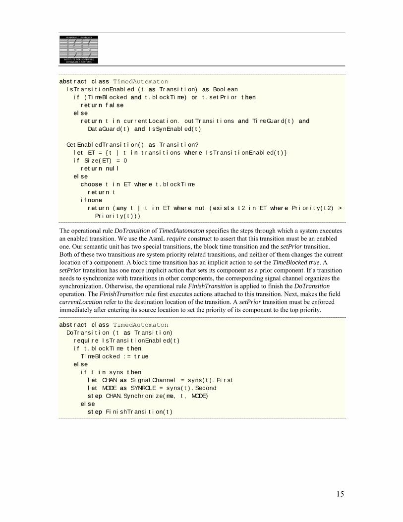
The operational rule DoTransition of TimedAutomaton specifies the steps through which a system executes an enabled transition. We use the AsmL require construct to assert that this transition must be an enabled one. Our semantic unit has two special transitions, the block time transition and the setPrior transition. Both of these two transitions are system priority related transitions, and neither of them changes the current location of a component. A block time transition has an implicit action to set the TimeBlocked true. A setPrior transition has one more implicit action that sets its component as a prior component. If a transition needs to synchronize with transitions in other components, the corresponding signal channel organizes the synchronization. Otherwise, the operational rule FinishTransition is applied to finish the DoTransition operation. The FinishTransition rule first executes actions attached to this transition. Next, makes the field currentLocation refer to the destination location of the transition. A setPrior transition must be enforced immediately after entering its source location to set the priority of its component to the top priority.
abstract class TimedAutomaton DoTransition (t as Transition)
require IsTransitionEnabled(t)
if t.blockTime then
TimeBlocked := true
else
if t in syns then
let CHAN as SignalChannel = syns(t).First
let MODE as SYNROLE = syns(t).Second
step CHAN.Synchronize(me, t, MODE)
else
step FinishTransition(t)
15
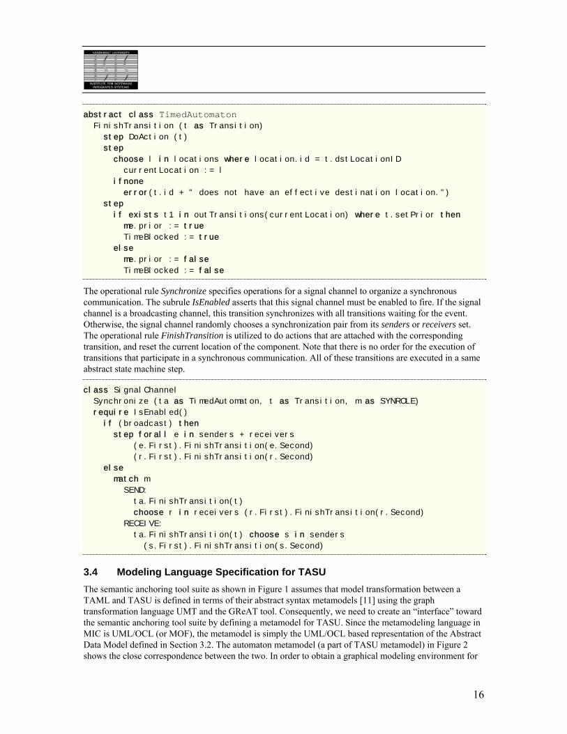
abstract class TimedAutomaton FinishTransition (t as Transition)
step DoAction (t)
step
choose l in locations where location.id = t.dstLocationID
currentLocation := l
ifnone
error(t.id + " does not have an effective destination location.")
step
if exists t1 in outTransitions(currentLocation) where t.setPrior then
me.prior := true
TimeBlocked := true
else
me.prior := false
TimeBlocked := false
The operational rule Synchronize specifies operations for a signal channel to organize a synchronous communication. The subrule IsEnabled asserts that this signal channel must be enabled to fire. If the signal channel is a broadcasting channel, this transition synchronizes with all transitions waiting for the event. Otherwise, the signal channel randomly chooses a synchronization pair from its senders or receivers set. The operational rule FinishTransition is utilized to do actions that are attached with the corresponding transition, and reset the current location of the component. Note that there is no order for the execution of transitions that participate in a synchronous communication. All of these transitions are executed in a same abstract state machine step.
class SignalChannel
Synchronize (ta as TimedAutomaton, t as Transition, m as SYNROLE)
require IsEnabled()
if (broadcast) then
step forall e in senders + receivers
(e.First).FinishTransition(e.Second)
(r.First).FinishTransition(r.Second)
else
match m
SEND:
ta.FinishTransition(t)
choose r in receivers (r.First).FinishTransition(r.Second)
RECEIVE:
ta.FinishTransition(t) choose s in senders
(s.First).FinishTransition(s.Second)
3.4 Modeling Language Specification for TASU The semantic anchoring tool suite as shown in Figure 1 assumes that model transformation between a TAML and TASU is defined in terms of their abstract syntax metamodels [11] using the graph transformation language UMT and the GReAT tool. Consequently, we need to create an “interface” toward the semantic anchoring tool suite by defining a metamodel for TASU. Since the metamodeling language in MIC is UML/OCL (or MOF), the metamodel is simply the UML/OCL based representation of the Abstract Data Model defined in Section 3.2. The automaton metamodel (a part of TASU metamodel) in Figure 2 shows the close correspondence between the two. In order to obtain a graphical modeling environment for
16

TASU, we also specified the metamodel in MetaGME. The MetaGME specification adds concrete syntax information to the metamodel and can be used for “meta-programming” the GME tool suite to create a modeling environment. (Detailed specifications and the full environment can be downloaded from [14].)
Figure 2. The automaton metamodel for TASU
The semantic anchoring tool suite provides a translator, which translates TASU models built in the GME modeling environment into AsmL domain models (i.e. instances of the Abstract Data Model). To illustrate this process, we show in Figure 3 a simple TASU automaton model and its equivalent representation in AsmL. This generated AsmL data model can be simulated according to the operational semantics defined in Section 3.3.
Figure 3. A TASU automaton (ComponentKindA)
17
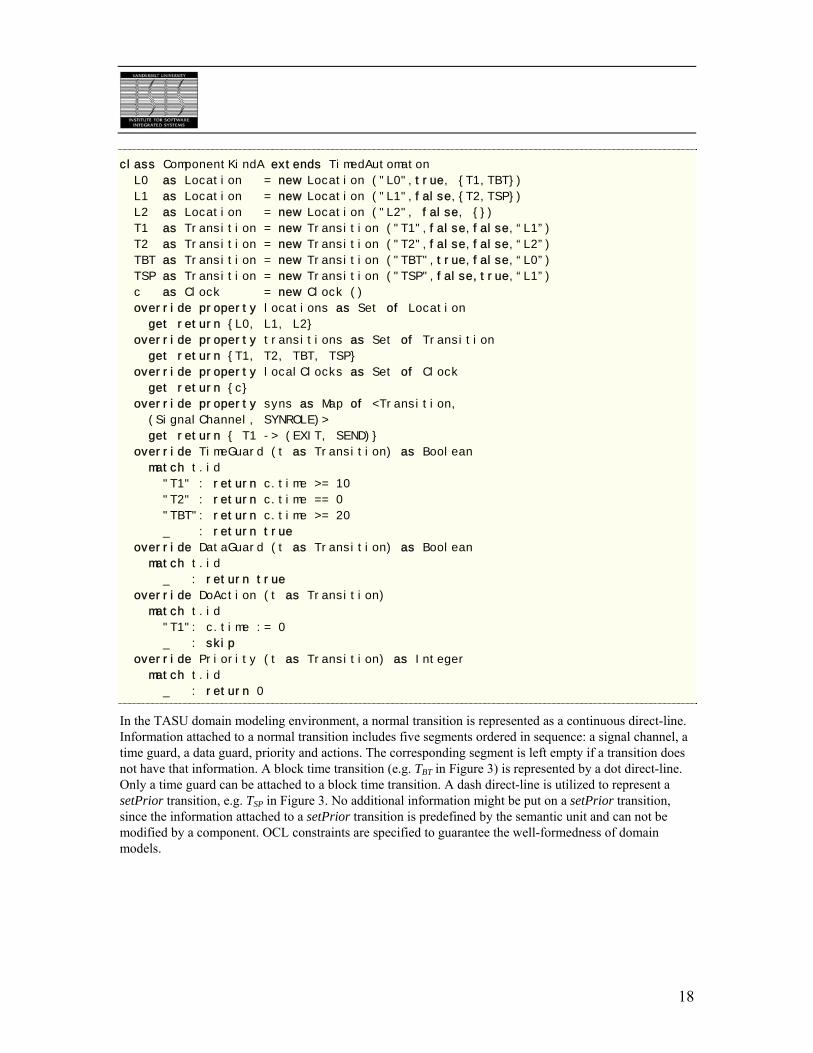
class ComponentKindA extends TimedAutomaton
L0 as Location = new Location ("L0",true, {T1,TBT})
L1 as Location = new Location ("L1",false,{T2,TSP})
L2 as Location = new Location ("L2", false, {})
T1 as Transition = new Transition ("T1",false,false,“L1”)
T2 as Transition = new Transition ("T2",false,false,“L2”)
TBT as Transition = new Transition ("TBT",true,false,“L0”)
TSP as Transition = new Transition ("TSP",false,true,“L1”)
c as Clock = new Clock ()
override property locations as Set of Location
get return {L0, L1, L2}
override property transitions as Set of Transition
get return {T1, T2, TBT, TSP}
override property localClocks as Set of Clock
get return {c}
override property syns as Map of <Transition,
(SignalChannel, SYNROLE)>
get return { T1 -> (EXIT, SEND)}
override TimeGuard (t as Transition) as Boolean
match t.id
"T1" : return c.time >= 10
"T2" : return c.time == 0
"TBT": return c.time >= 20
_ : return true
override DataGuard (t as Transition) as Boolean
match t.id
_ : return true
override DoAction (t as Transition)
match t.id
"T1": c.time := 0
_ : skip
override Priority (t as Transition) as Integer
match t.id
_ : return 0
In the TASU domain modeling environment, a normal transition is represented as a continuous direct-line. Information attached to a normal transition includes five segments ordered in sequence: a signal channel, a time guard, a data guard, priority and actions. The corresponding segment is left empty if a transition does not have that information. A block time transition (e.g. TBT in Figure 3) is represented by a dot direct-line. Only a time guard can be attached to a block time transition. A dash direct-line is utilized to represent a setPrior transition, e.g. TSP in Figure 3. No additional information might be put on a setPrior transition, since the information attached to a setPrior transition is predefined by the semantic unit and can not be modified by a component. OCL constraints are specified to guarantee the well-formedness of domain models.
18
4. Semantic Anchoring to TASU Semantic anchoring of a TAML means defining the transformation to TASU. In MIC, this transformation is defined in terms of the TAML and TASU metamodels. As it is shown in Figure 1, the specification of the transformation (which is the transformational semantics of the selected TAML) can be directly used for automatically generating a model transformer, which can translate TAML models into TASU models. (The TASU models (as we showed it above) can then be translated into AsmL data models if we want to obtain a simulation using the specification of the semantics.) In this section, we illustrate the semantic anchoring from the UPPAAL and IF languages to TASU. It must be noted that we do not consider in this paper the verification of the semantic equivalence between our specification and those used internally by the tools. We also have to restrict the description of the transformations due to space limitations. The full specifications by using our semantic anchoring tool suite can be downloaded from [14].
4.1 Semantic Anchoring for the UPPAAL Language A trivial one-to-one mapping can realize the anchoring for those modeling constructs that are the same both in the UPPAAL language and in TASU. In this section we show examples for transformation rules that map modeling constructs that exist in UPPAAL but not in the semantic unit.
4.1.1 Location invariants
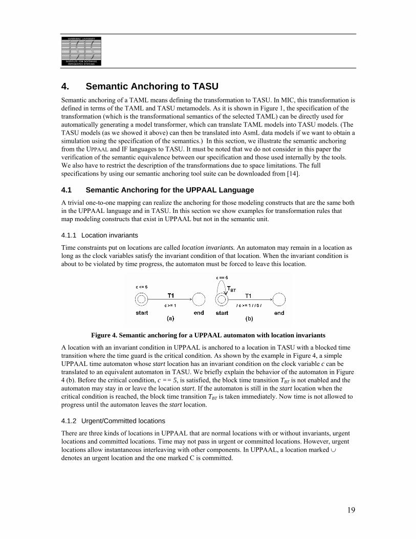
Time constraints put on locations are called location invariants. An automaton may remain in a location as long as the clock variables satisfy the invariant condition of that location. When the invariant condition is about to be violated by time progress, the automaton must be forced to leave this location.
Figure 4. Semantic anchoring for a UPPAAL automaton with location invariants
A location with an invariant condition in UPPAAL is anchored to a location in TASU with a blocked time transition where the time guard is the critical condition. As shown by the example in Figure 4, a simple UPPAAL time automaton whose start location has an invariant condition on the clock variable c can be translated to an equivalent automaton in TASU. We briefly explain the behavior of the automaton in Figure 4 (b). Before the critical condition, c == 5, is satisfied, the block time transition TBT is not enabled and the automaton may stay in or leave the location start. If the automaton is still in the start location when the critical condition is reached, the block time transition TBT is taken immediately. Now time is not allowed to progress until the automaton leaves the start location.
4.1.2 Urgent/Committed locations
There are three kinds of locations in UPPAAL that are normal locations with or without invariants, urgent locations and committed locations. Time may not pass in urgent or committed locations. However, urgent locations allow instantaneous interleaving with other components. In UPPAAL, a location marked ∪ denotes an urgent location and the one marked C is committed.
19
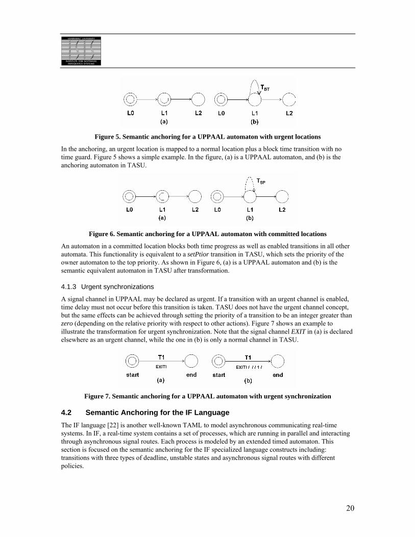
Figure 5. Semantic anchoring for a UPPAAL automaton with urgent locations
In the anchoring, an urgent location is mapped to a normal location plus a block time transition with no time guard. Figure 5 shows a simple example. In the figure, (a) is a UPPAAL automaton, and (b) is the anchoring automaton in TASU.
Figure 6. Semantic anchoring for a UPPAAL automaton with committed locations
An automaton in a committed location blocks both time progress as well as enabled transitions in all other automata. This functionality is equivalent to a setPtior transition in TASU, which sets the priority of the owner automaton to the top priority. As shown in Figure 6, (a) is a UPPAAL automaton and (b) is the semantic equivalent automaton in TASU after transformation.
4.1.3 Urgent synchronizations
A signal channel in UPPAAL may be declared as urgent. If a transition with an urgent channel is enabled, time delay must not occur before this transition is taken. TASU does not have the urgent channel concept, but the same effects can be achieved through setting the priority of a transition to be an integer greater than zero (depending on the relative priority with respect to other actions). Figure 7 shows an example to illustrate the transformation for urgent synchronization. Note that the signal channel EXIT in (a) is declared elsewhere as an urgent channel, while the one in (b) is only a normal channel in TASU.
Figure 7. Semantic anchoring for a UPPAAL automaton with urgent synchronization
4.2 Semantic Anchoring for the IF Language The IF language [22] is another well-known TAML to model asynchronous communicating real-time systems. In IF, a real-time system contains a set of processes, which are running in parallel and interacting through asynchronous signal routes. Each process is modeled by an extended timed automaton. This section is focused on the semantic anchoring for the IF specialized language constructs including: transitions with three types of deadline, unstable states and asynchronous signal routes with different policies.
20

4.2.1 Lazy/Delayable/Eager transitions
The IF language does not support location invariants explicitly, but the same behavior can be achieved through utilizing transitions with different deadlines. An IF transition may have one of three types of deadlines (lazy, delayable and eager), which indicates the priority of a transition with respect to time progress. A lazy transition is never urgent and always allows time progress. An eager transition is urgent and prohibits time progress as soon as it is enabled. A delayable transition becomes urgent when it is about to be disabled by time progress and allows time progress otherwise. A lazy transition is equivalent to a normal transition in TASU with a priority value zero. The same behavior for an eager transition can be achieved by setting the priority of the corresponding transition in TASU to be an integer greater than zero (depending on the relative priority with respect to other actions).
A delayable transition implies that the priority of this transition jumps to a higher value than that of time progress when the enabling condition of this transition is about to be violated by time progress. An example for the transformation is shown in Figure 8. Note that the transition T1 in (a) is an IF delayable transition while the one in (b) is a normal transition in TASU. We give a briefly explanation for the behavior of the IF automaton in (a). During 10 <= c < 20 (where c is a clock variable), the transition T1 is enabled but the system can randomly make choices on whether it takes this transition or advances time. When c == 20 is reached, the transition T1 will be disabled by any further time progress. At this moment, the system should execute T1 before advancing time. The automaton in the Figure 8 (b) employs the expression if c == 20 return1 else return 0 to specify the dynamic priority of this transition. The priority of the T1 transition jumps to a higher value than the time progress priority (zero), which ensures T1 to be executed as soon as c reaches 20, if the automaton is still in the Start location.
Figure 8. Semantic anchoring for an IF automaton with delayable transitions
4.2.2 Unstable locations
Unstable locations in IF have similar meaning to committed locations in UPPAAL. A process entering an unstable location must continue immediately by firing some transitions at that location and soon on, until a stable location will be reached. Unstable locations is an IF way to define an atomic action as a sequence of transitions from one stable location to another stable location. So the anchoring approach for an IF unstable location is also the same as that for a UPPAAL committed location. Like the approach shown in Figure 6, each unstable location in IF is mapped to a normal location with a setPrior transition in the semantic unit.
4.2.3 Asynchronous signal routes
The IF language imports a language construct, the signal route, to facilitate modeling the asynchronous communications among processes. Signal routes can be thought as specialized processes for the delivery of signals between normal processes. The behavior of signal routes is implicitly defined by a set of policies, including: queueing policy (with two options, #fifo and #multiset), reliability policy (with two options, #reliable and #lossy), delivering policy (with three options #peer, #unicast and #multicase) and delaying policy (with three options, #urgent, #delay[a, b] and #rate[a, b]). The option #delay[a, b] means that any message entering the signal route will eventually leave it after a and not later than b units of time. The option #rate[a, b] means that it takes between a and b units of time per message to be delivered by the signal route. Please refer to [22] for the meaning of other policies and options.
21
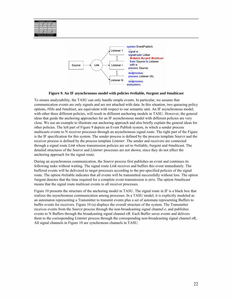
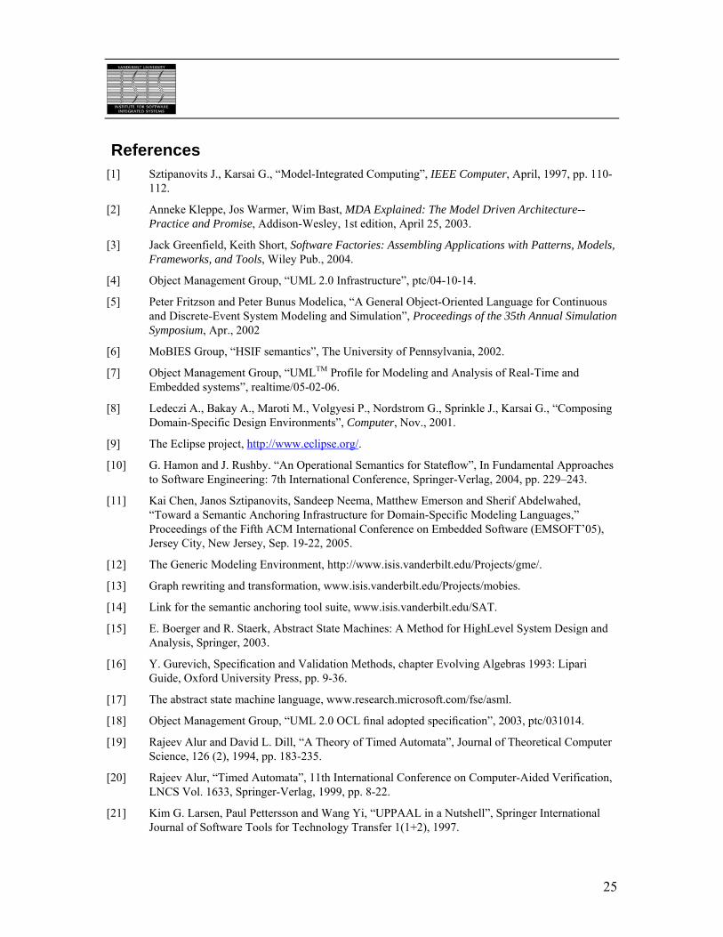
Figure 9. An IF asynchronous model with policies #reliable, #urgent and #multicast
To ensure analyzability, the TASU can only handle simple events. In particular, we assume that communication events are only signals and are not attached with data. In this situation, two queueing policy options, #fifo and #multiset, are equivalent with respect to our semantic unit. An IF asynchronous model, with other three different policies, will result in different anchoring models in TASU. However, the general ideas that guide the anchoring approaches for an IF asynchronous model with different policies are very close. We use an example to illustrate our anchoring approach and also briefly explain the general ideas for other policies. The left part of Figure 9 depicts an Event Publish system, in which a sender process multicasts events to N receiver processes through an asynchronous signal route. The right part of the Figure is the IF specification for this system. The sender process is defined by the process template Source and the receiver process is defined by the process template Listener. The sender and receivers are connected through a signal route Link whose transmission policies are set to #reliable, #urgent and #multicast. The detailed structures of the Source and Listener processes are not shown, since they do not affect the anchoring approach for the signal route.
During an asynchronous communication, the Source process first publishes an event and continues its following tasks without waiting. The signal route Link receives and buffers this event immediately. The buffered events will be delivered to target processes according to the pre-specified policies of the signal route. The option #reliable indicates that all events will be transmitted successfully without loss. The option #urgent denotes that the time required for a complete event transmission is zero. The option #multicast means that the signal route multicast events to all receiver processes.
Figure 10 presents the structure of the anchoring model in TASU. The signal route in IF is a black box that realizes the asynchronous communication among processes. In a TASU model, it is explicitly modeled as an automaton representing a Transmitter to transmit events plus a set of automata representing Buffers to buffer events for receivers. Figure 10 (a) displays the overall structure of the system. The Transmitter receives events from the Source process through the non-broadcasting signal channel e, and publishes events to N Buffers through the broadcasting signal channel eR. Each Buffer saves events and delivers them to the corresponding Listener process through the corresponding non-broadcasting signal channel eRi. All signal channels in Figure 10 are synchronous channels in TASU.
22

Figure 10. The semantic anchoring model for the IF asynchronous model in Figure 9
In this report, we omit the verification for the semantic equivalence between the IF asynchronous model in Figure 9 and the TASU synchronous model in Figure 10. If the policies of an asynchronous model are changed, the synchronous model also needs to be modified to capture the changed behavior. In fact, there may have multiple solutions to capture the changed behavior. However, we give a simple solution as a clue for other possible approaches.
The behavior of the reliability policy #lossy can be achieved through adding transitions in the loaded location of the Transmitter, which randomly drop buffered events. If the signal channel eR is set as a non-broadcasting channel, the model in Figure 10 has the same behavior as the model in Figure 9 with the delivering policy set to #unicast, which means that an event is delivered to a randomly selected receiver process. If the delivery policy is set to #peer, the source process must specify a specific target process to send events. In this case, the synchronous model has only one Listener process and one Buffer process. So, it runs in the same manner as the corresponding asynchronous model applying the delivery policy #peer. The delaying policy #delay[a, b] can be achieved by adding local clock variables to measure the buffered time for each received event, and adding time conditions and dynamic priorities on the publishing events transitions (T2 and T4) of the Transmitter to control the delay for the event delivering. Similarly, the delaying policy # rate[a, b] can be captured through adding a local clock variable to measure the time passing for the Transmitter, and adding time guards and dynamic priorities on the publishing events transitions (T2 and T4) to control the rate of the event delivering.
23

5. Conclusions and Future Work As application of model-based approaches extends to safety critical embedded systems, precise specification of behavioral semantics of DSMLs is becoming a crucial issue. We believe that semantic anchoring can provide a theoretically solid yet practical solution. Essential components of our proposed semantic anchoring infrastructure are the “semantic units”; the core behavioral abstractions that are widely used in many DSMLs. In this report we described considerations we used for defining a common semantic unit for DSMLs that use (possible as a behavioral aspect) timed automata semantics. We have found that complexity of semantic unites needs to be determined by balancing between the needs of understandability and the difficulty of developing transformations. We expect that the existence of well defined and carefully structured semantic units will encourage developers of DSMLs to consider semantic issues much more explicitly than currently. Besides experimenting with semantic unit specifications, we are working on their compositions and on various use cases for deep semantic integration of complex tool chains.
24
References [1] Sztipanovits J., Karsai G., “Model-Integrated Computing”, IEEE Computer, April, 1997, pp. 110-
112.
[2] Anneke Kleppe, Jos Warmer, Wim Bast, MDA Explained: The Model Driven Architecture--Practice and Promise, Addison-Wesley, 1st edition, April 25, 2003.
[3] Jack Greenfield, Keith Short, Software Factories: Assembling Applications with Patterns, Models, Frameworks, and Tools, Wiley Pub., 2004.
[4] Object Management Group, “UML 2.0 Infrastructure”, ptc/04-10-14.
[5] Peter Fritzson and Peter Bunus Modelica, “A General Object-Oriented Language for Continuous and Discrete-Event System Modeling and Simulation”, Proceedings of the 35th Annual Simulation Symposium, Apr., 2002
[6] MoBIES Group, “HSIF semantics”, The University of Pennsylvania, 2002.
[7] Object Management Group, “UMLTM Profile for Modeling and Analysis of Real-Time and Embedded systems”, realtime/05-02-06.
[8] Ledeczi A., Bakay A., Maroti M., Volgyesi P., Nordstrom G., Sprinkle J., Karsai G., “Composing Domain-Specific Design Environments”, Computer, Nov., 2001.
[9] The Eclipse project, http://www.eclipse.org/.
[10] G. Hamon and J. Rushby. “An Operational Semantics for Stateflow”, In Fundamental Approaches to Software Engineering: 7th International Conference, Springer-Verlag, 2004, pp. 229–243.
[11] Kai Chen, Janos Sztipanovits, Sandeep Neema, Matthew Emerson and Sherif Abdelwahed, “Toward a Semantic Anchoring Infrastructure for Domain-Specific Modeling Languages,” Proceedings of the Fifth ACM International Conference on Embedded Software (EMSOFT’05), Jersey City, New Jersey, Sep. 19-22, 2005.
[12] The Generic Modeling Environment, http://www.isis.vanderbilt.edu/Projects/gme/.
[13] Graph rewriting and transformation, www.isis.vanderbilt.edu/Projects/mobies.
[14] Link for the semantic anchoring tool suite, www.isis.vanderbilt.edu/SAT.
[15] E. Boerger and R. Staerk, Abstract State Machines: A Method for HighLevel System Design and Analysis, Springer, 2003.
[16] Y. Gurevich, Specification and Validation Methods, chapter Evolving Algebras 1993: Lipari Guide, Oxford University Press, pp. 9-36.
[17] The abstract state machine language, www.research.microsoft.com/fse/asml.
[18] Object Management Group, “UML 2.0 OCL final adopted specification”, 2003, ptc/031014.
[19] Rajeev Alur and David L. Dill, “A Theory of Timed Automata”, Journal of Theoretical Computer Science, 126 (2), 1994, pp. 183-235.
[20] Rajeev Alur, “Timed Automata”, 11th International Conference on Computer-Aided Verification, LNCS Vol. 1633, Springer-Verlag, 1999, pp. 8-22.
[21] Kim G. Larsen, Paul Pettersson and Wang Yi, “UPPAAL in a Nutshell”, Springer International Journal of Software Tools for Technology Transfer 1(1+2), 1997.
25
[22] Marius Bozga, Susanne Graf, Ileana Ober, Iulian Ober and Joseph Sifakis, “Tools and
Applications II: The IF Toolset”, In Flavio Corradinni and Marco Bernanrdo,editors, Proceedings of SFM'04 (Bertinoro, Italy), LNCS vol. 3185, Springer-Verlag, 2004.
[23] Sergio Yovine, “Kronos: a Verification Tool for Real-time Systems”, Journal on Software Tools for Technology Transfer, 1, October 1997.
[24] Susan Graph, Ileana Ober: “How Useful is the UML profile SPT Without Semantics?”, Workshop on the usage of the UML profile for Scheduling, Performance and Time (SIVOES '04), Toronto Canada, 2004.
[25] Karsai G., Sztipanovits J., Ledeczi A., Bapty T., “Model-Integrated Development of Embedded Software”, Proceedings of the IEEE, Vol. 91, Number 1, January, 2003.
26

27
Appendix: Metamodels for Graphical Languages The Generic Modeling Environment (GME) uses an UML-based approach to define modeling languages. The underlying assumption is that graphical modeling languages have “sentences” formed from objects, i.e. a sentence is a network of objects. A UML class diagram can capture multiple classes, their attributes, and their relationships: inheritance, containment, and general associations. A programmer can instantiate those classes, specify instance attributes, and establish links among objects that correspond to associations in the class diagram. Therefore, a UML class diagram is a finite description of an infinite number of object networks that comply with it, not unlike a context-free grammar is a finite description of a (potentially infinite) language.
Figure11: An example meta-model
Unfortunately, pure UML class diagrams are not well suited for the metaprogramming of modeling environments. The reason is that environments tend to support some core modeling concepts (e.g. containers, ported objects, atomic objects, etc.), which are not UML concepts, yet metamodels should contain hints how UML class diagrams should be interpreted in terms of those concepts. A convenient solution to this problem is to use stereotypes, which mark classes as belonging to a specific category that is meaningful for (and has a specific semantics in) the modeling environment. Stereotypes are part of the UML standard, but in UML they do not have a specific interpretation —they are simply indicators marking classes as members of some category of classes. In the metaprogrammable Generic Modeling Environment this approach has been chosen. Figure1 below illustrates how a UML class diagram can be embellished to define a meta-model for GME. The drawing also summarizes the core model organization concepts supported by GME. GME provides the following set of organization concepts: folders (containers), models (ported hierarchical composite objects), atoms (primitive objects), connections (wires), sets (groups of objects), and references (pointers to models, atoms, sets, or other references). The diagram on Figure1, read as a pure UML diagram, has the following classes: aFolder: an untyped container of objects, aModel: a typed container with model semantics, anAtom and anotherAtom: simple objects, aConnection: an association class relating the classes anAtom and anotherAtom, anotherModel: a container for anotherAtoms and anotherModels, aSet: yet another container containing aSetElement, and aReference: associates with (“points to”) anotherAtoms. The stereotypes map these classes into environment-specific modeling concepts. GME supports <<Model>>-s, which are composite objects with ports containing other objects (including other <<Model>>-s), <<Atom>>-s are primitive objects that have their own graphical icons, <<Set>>-s are special containers that contain objects within the same parent <<Model>> that also contains the set, <<References>> are alias objects which point to (non-

local) objects in the object hierarchy, and <<Connection>>-s are association objects relating and two (or more) iconic objects. All objects except the <<Connection>>-s are iconic. <<Model>>-s can have ports on their icons, and <<Connection>>-s are visualized as lines. It is not shown on the drawing, but many stereotypes have a corresponding “proxy” stereotype, which is semantically equivalent to the base stereotype. These stereotypes can be recognized by their name, which follows the form <<...Proxy>>. A class with name X with stereotype <<S>> can be referred to on another diagram by a class with name X with stereotype <<SProxy>>. The metamodel element appearing on the “other” diagram denotes the same metamodel element as X. This allows reducing visual clutter.
28