design & fabrication of 360° flexible drilling machine · international journal of engineering...
TRANSCRIPT
International Journal of Engineering Trends and Applications (IJETA) – Volume 5 Issue 2, Mar-Apr 2018
ISSN: 2393-9516 www.ijetajournal.org Page 346
Design & Fabrication of 360° Flexible Drilling Machine
G.Prasanth Kumar [1], P.Guna Sekhar [2], P.Nadeem Khan [3]
P.Rajesh [4], B.V.Krishnaiah [5] Under Graduate Student [1], [2], [3], [4], Assistant professor [5]
Department of Mechanical Engineering
Narayana Engineering College, Gudur
Andhra Pradesh – India
ABSTRACT In previous drilling machine many of the problems arise during drilling. Some parts cannot drill due to small work
space between drill bit and work piece. So we use hand drills in this cases but it cause alignment problems. So here i
propose a 360 degree flexible drill that can be mounted on a table or wall and can be used to drill holes horizontally,
vertically or even upside down. So this make it possible for easy drilling in even complicated parts and surfaces.
Keywords:- 360˚, Flexibility, Drill Bit
І. INTRODUCTION Drill machines have been the heart of every industry.
Drilling holes in parts, sheets and structures is a
regular industrial work. Perfect and well aligned
drilling needs fixed and strong drills. Some parts
cannot be drilled using fixed drills due to low space
between drill bit and drill bed. We need to use hand
drills in such cases but hand drills have alignment
problems while drilling. So here i propose a 360º
flexible drill that can be mounted on a table or wall
and can be used to drill holes horizontally , vertically
or even upside down. So this makes it possible for
easy drilling in even complicated parts and surfaces.
Thus i use rotating hinges and connectors with motor
mount and supporting structure to design and
fabricate a 360 degree drilling machine for easy
drilling operations. Drilling machine is one of the
most important machine tools in a workshop. It was
designed to produce a cylindrical hole of required
diameter and depth on metal work pieces. Though
holes can be made by different machine tools in a
shop, drilling machine is designed specifically to
perform the operation of drilling and similar
operations. Drilling can be done easily at a low cost
in a shorter period of time in a drilling
machine.Drilling can be called as the operation of
producing a cylindrical hole of required diameter and
depth by removing metal by the rotating edges of a
drill. The cutting tool known as drill is fitted into the
spindle of the drilling machine. A mark of
indentation is made at the required location with a
center punch. The rotating drill is pressed at the
location and is fed into the work. The hole can be
made up to a required depth. Drilled holes are
characterized by their sharp edge on the entrance side
and the presence of burrs on the exit side (unless they
have been removed). Also, the inside of the hole
usually has helical feed marks. Drilling may affect
the mechanical properties of the work piece by
creating low residual stresses around the whole
opening and a very thin layer of highly stressed and
disturbed material on the newly formed surface.
A. Drilling Machine Construction The basic parts of a drilling machine are its base,
supporting arms, drill head and chuck. The base
made of cast iron or other hard material may rest on a
bench, floor depending upon the design. Larger and
heavy duty machines are grounded on the floor. The
arms are mounted on base with the help of hinge to
rotate about it. It is accurately machined and the arms
can move up, down and rotate about x-axis. The drill
chuck, an electric motor and the mechanism meant
for driving the chuck at different speeds are mounted
on the top of the upper arm. Power is transmitted
from the electric motor to the drill chuck.
B. Drilling Machine Working Principle
The working principle of this flexible drilling
machine is initially started from the D.C. motor
through full wave rectifier. In which there is one
power sources, received from the rectifier. Then the
arm rotates at 360 degree and moves anywhere when
drilling is required up to its maximum arm length.
With the help of my project we can drill in
complicated parts accurately.
ІІ. MATERIALS & METHODS My project even be rotate easily drill at any direction.
So that job setting operation is not complicated as
well as reduces the setting time for the operation. It
also takes into consideration the most effective
RESEARCH ARTICLE OPEN ACCESS

International Journal of Engineering Trends and Applications (IJETA) – Volume 5 Issue 2, Mar-Apr 2018
ISSN: 2393-9516 www.ijetajournal.org Page 347
method of controlling the drilling machine by
manually. Materials like wood, plastic and light
metals drilled with this. The work piece is fixed on
the work table.As the machine tool exert Vertical
pressure to original a hole it loosely called a drill
press. This Drilling is performed for Different
Position Drilling in the working job. Up/Down and
rotating mechanism is available in this Drilling
Machine. One end of the arm is attached to a firm
base while the other has a tool. These arms are made
up of Aluminum. The number of parameters in the
subgroup is called the degrees of freedom of the
joint. Mechanical linkages are usually designed to
transform a given input force and movement into a
desired output force and movement.
Fig. 1: (a) Rotation of Upper Arm about Vertical
Hinge
Fig. 2: (b) Rotation of Bottom Arm about Vertical
Hinge
Fig. 3: (c) Up/Down Movement of Bottom Arm
about Horizontal Hinge
Fig. 4: (d) Up/Down Movement of Upper Arm about
Horizontal Hinge
Fig. 5: – 360 Degree Flexible Drilling Machine
III. LITERATURE REVIEW
In order to model surface roughness, several methods
had been used in previous research. Mr. K. I.
Nargatti, Mr. S. V. Patil , Mr. G. N. Rakate (2016)
developed a model in Multispindle Drilling Head
with Varying Centre Distance. Multiple-spindle
drilling machines are used for mass production, a
great time saver where many pieces of jobs having
many holes are to be drilled. Multi-spindle head
machines are used in mechanical industry in order to
increase the productivity of machining systems. This
machine has two spindles driven by a single motor
and all the spindles are fed in to the work piece
simultaneously. Feeding motions are obtained either
by raising the work table or by lowering the drills
head. As the name indicates multiple spindle drilling
machines have two spindles driven by a single power
head, and these two spindles holding the drill bits are
fed into the work piece simultaneously. The spindles
are so constructed that their centre distance can be
adjusted in any position within the drill head
depending on the job requirement. The positions of
International Journal of Engineering Trends and Applications (IJETA) – Volume 5 Issue 2, Mar-Apr 2018
ISSN: 2393-9516 www.ijetajournal.org Page 348
those parallel shafts holding the drills are adjusted
depending upon the locations of the holes to be made
on the job. Based on the literature review, the most
parameters that widely considered when investigating
the operation of a machine are feed rate, spindle
speed and depth of cut. Most of the researches didn’t
consider the uncontrolled parameters, such as tool
geometry, tool wear, chip loads, and chip formations,
or the material properties of both tool and work
piece.
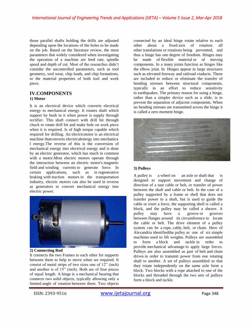
ΙV.COMPONENTS 1) Motor
It is an electrical device which converts electrical
energy to mechanical energy. It rotates shaft which
support by bush in it when power is supply through
rectifier. This shaft connect with drill bit through
chuck to rotate drill bit and make hole on work piece
when it is required. Is of high torque capable which
required for drilling. An electricmotor is an electrical
machine thatconverts electricalenergy into mechanica
l energy.The reverse of this is the conversion of
mechanical energy into electrical energy and is done
by an electric generator, which has much in common
with a motor.Most electric motors operate through
the interaction between an electric motor's magnetic
field and winding currents to generate force. In
certain applications, such as in regenerative
braking with traction motors in the transportation
industry, electric motors can also be used in reverse
as generators to convert mechanical energy into
electric power.
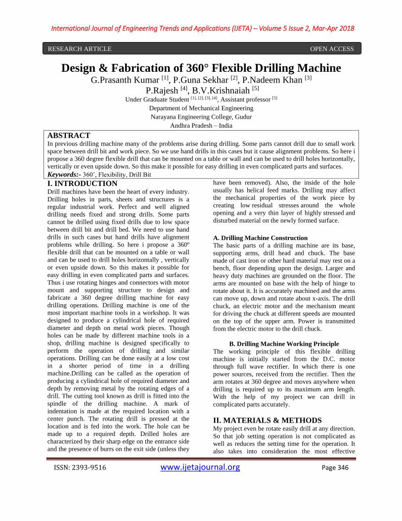
2) Connecting Rod
It connects the two Frames to each other for supports
between them to help to move when we required. It
consist of metal strips of two sizes one of 12” (inch)
and another is of 15” (inch). Both are of four pieces
of equal length. A hinge is a mechanical bearing that
connects two solid objects, typically allowing only a
limited angle of rotation between them. Two objects
connected by an ideal hinge rotate relative to each
other about a fixed axis of rotation: all
other translations or rotations being prevented, and
thus a hinge has one degree of freedom. Hinges may
be made of flexible material or of moving
components. In a many joints function as hinges like
the elbow joint. In Hinges appear in large structures
such as elevated freeway and railroad viaducts. These
are included to reduce or eliminate the transfer of
bending stresses between structural components,
typically in an effort to reduce sensitivity
to earthquakes. The primary reason for using a hinge,
rather than a simpler device such as a slide, is to
prevent the separation of adjacent components. When
no bending stresses are transmitted across the hinge it
is called a zero moment hinge.
3) Pulleys
A pulley is a wheel on an axle or shaft that is
designed to support movement and change of
direction of a taut cable or belt, or transfer of power
between the shaft and cable or belt. In the case of a
pulley supported by a frame or shell that does not
transfer power to a shaft, but is used to guide the
cable or exert a force, the supporting shell is called a
block, and the pulley may be called a sheave. A
pulley may have a groove or grooves
between flanges around its circumference to locate
the cable or belt. The drive element of a pulley
system can be a rope, cable, belt, or chain. Hero of
Alexandria identifiedthe pulley as one of six simple
machines used to lift weights. Pulleys are assembled
to form a block and tackle in order to
provide mechanical advantage to apply large forces.
Pulleys are also assembled as part of belt and chain
drives in order to transmit power from one rotating
shaft to another. A set of pulleys assembled so that
they rotate independently on the same axle form a
block. Two blocks with a rope attached to one of the
blocks and threaded through the two sets of pulleys
form a block and tackle.
International Journal of Engineering Trends and Applications (IJETA) – Volume 5 Issue 2, Mar-Apr 2018
ISSN: 2393-9516 www.ijetajournal.org Page 349
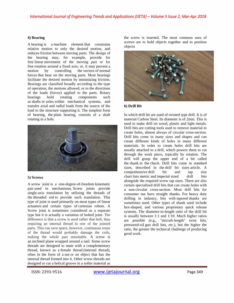
4) Bearing
A bearing is a machine element that constrains
relative motion to only the desired motion, and
reduces friction between moving parts. The design of
the bearing may, for example, provide for
free linear movement of the moving part or for
free rotation around a fixed axis; or, it may prevent a
motion by controlling the vectors of normal
forces that bear on the moving parts. Most bearings
facilitate the desired motion by minimizing friction.
Bearings are classified broadly according to the type
of operation, the motions allowed, or to the directions
of the loads (forces) applied to the parts. Rotary
bearings hold rotating components such
as shafts or axles within mechanical systems, and
transfer axial and radial loads from the source of the
load to the structure supporting it. The simplest form
of bearing, the plain bearing, consists of a shaft
rotating in a hole.
5) Screws
A screw joint is a one-degree-of-freedom kinematic
pair used in mechanisms. Screw joints provide
single-axis translation by utilizing the threads of
the threaded rod to provide such translation. This
type of joint is used primarily on most types of linear
actuators and certain types of cartesian robots. A
Screw joint is sometimes considered as a separate
type but it is actually a variation of bolted joint. The
difference is that a screw is used rather that bolt, thus
requiring an internal thread in one of the jointed
parts. This can save space, however, continuous reuse
of the thread would probably damage the coils,
making the whole part unsuitable. A screw is
an inclined plane wrapped around a nail. Some screw
threads are designed to mate with a complementary
thread, known as a female thread (internal thread),
often in the form of a nut or an object that has the
internal thread formed into it. Other screw threads are
designed to cut a helical groove in a softer material as
the screw is inserted. The most common uses of
screws are to hold objects together and to position
objects
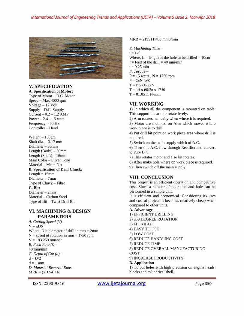
6) Drill Bit
In which drill bit are used of twisted type drill. It is of
material Carbon Steel. Its diameter is of 2mm. This is
used to make drill on wood, plastic and light metals.
Drill bits are cutting tools used to remove material to
create holes, almost always of circular cross-section.
Drill bits come in many sizes and shapes and can
create different kinds of holes in many different
materials. In order to create holes drill bits are
usually attached to a drill, which powers them to cut
through the work piece, typically by rotation. The
drill will grasp the upper end of a bit called
the shank in the chuck. Drill bits come in standard
sizes, described in the drill bit sizes article. A
comprehensive drill bit and tap size
chart lists metric and imperial sized drill bits
alongside the required screw tap sizes. There are also
certain specialized drill bits that can create holes with
a non-circular cross-section. Most drill bits for
consumer use have straight shanks. For heavy duty
drilling in industry, bits with tapered shanks are
sometimes used. Other types of shank used include
hex-shaped, and various proprietary quick release
systems. The diameter-to-length ratio of the drill bit
is usually between 1:1 and 1:10. Much higher ratios
are possible (e.g., "aircraft-length" twist bits,
pressured-oil gun drill bits, etc.), but the higher the
ratio, the greater the technical challenge of producing
good work.
International Journal of Engineering Trends and Applications (IJETA) – Volume 5 Issue 2, Mar-Apr 2018
ISSN: 2393-9516 www.ijetajournal.org Page 350
V. SPECIFICATION A. Specification of Motor:
Type of Motor – D.C. Motor
Speed – Max 4000 rpm
Voltage – 12 Volt
Supply – D.C. Supply
Current – 0.2 – 1.2 AMP
Power – 2.4 – 15 watt
Frequency – 50 Hz
Controller – Hand
Weight – 150gm
Shaft dia. – 3.17 mm
Diameter – 36mm
Length (Body) – 50mm
Length (Shaft) – 16mm
Main Color – Silver Tone
Material – Metal Net
B. Specification of Drill Chuck:
Length = 15mm
Diameter = 7mm
Type of Chuck – Fibre
C. Bit:
Diameter – 2mm
Material – Carbon Steel
Type of Bit – Twist Drill Bit
VI. MACHINING & DESIGN
PARAMETERS A. Cutting Speed (V) –
V = πDN
Where, D = diameter of drill in mm = 2mm
N = speed of rotation in mm = 1750 rpm
V = 183.259 mm/sec
B. Feed Rate (f) –
40 mm/min
C. Depth of Cut (d) –
d = D/2
d = 1 mm
D. Material Removal Rate –
MRR = (πD2/4)f N
MRR = 219911.485 mm3/min
E. Machining Time –
t = L/f
Where, L = length of the hole to be drilled = 10cm
f = feed of the drill = 40 mm/min
t = 0.25 min
F. Torque –
P = 15 watts , N = 1750 rpm
P = 2πNT/60
T = P x 60/2πN
T = 15 x 60/2π x 1750
T = 81.8511 N-mm
VII. WORKING 1) In which all the component is mounted on table.
This support the arm to rotate freely.
2) Arm rotates manually when where it is required.
3) Motor are mounted on Arm which moves where
work piece is to drill.
4) Put drill bit point on work piece area where drill is
required.
5) Switch on the main supply which of A.C.
6) Then this A.C. flow through Rectifier and convert
to Pure D.C.
7) This rotates motor and also bit rotates.
8) After make hole where on work piece is required.
9) Then switch off the main supply.
VIIΙ. CONCLUSION This project is an efficient operation and competitive
cost. Since a number of operation and hole can be
performed in a simple unit.
It is efficient and economical. Considering its uses
and cost of project, it becomes relatively cheap when
compared to other units.
A. Advantage
1) EFFICIENT DRILLING
2) 360 DEGREE ROTATION
3) FLEXIBLE
4) EASY TO USE
5) LOW COST
6) REDUCE HANDLING COST
7) REDUCE TIME
8) REDUCE OVERALL MANUFACTURING
COST
9) INCREASE PRODUCTIVITY
B. Application
1) To put holes with high precision on engine heads,
blocks and cylindrical shell.

International Journal of Engineering Trends and Applications (IJETA) – Volume 5 Issue 2, Mar-Apr 2018
ISSN: 2393-9516 www.ijetajournal.org Page 351
2) Used in furniture making.
C. Future Scope
1) It is used in industries.
2) It is used with automation for automatic drilling.
3) In future it is used in every field where drilling is
required.
4) Also use this method of rotation of arm in other
machining operation.
REFERENCES [1] Mr. Jay M. Patel , Mr. Akhil P. Nair , Prof. Hiral
U.Chauhan , 3-Directional Flexible Drilling
Machine, International Journal for Scientific
Research & Development , Vol. 3, January 2015
, Pages 1262 – 1264
[2] Praveenkumar, B. S., Niranjan Hugar,
Ajithkumar, A. , DESIGN OF ROD
GROOVING MULTISPINDLE DRILLING
UNIT, Asian Journal of Science and Technology
, Vol.07, March,2016 , Pages 2600-2605
[3] Prof. Gadhia Utsav D, Shah Harsh A, Patel Viral
A, Patel Kushang P, Amin Harsh J , DESIGN &
DEVELOPMENT OF UNIVERSAL
PNEUMATIC DRILLING MACHINE: A
REVIEW STUDY, International Journal For
Technological Research In Engineering Volume
3, April-2016 , Pages 1614 – 1616
[4] N.VENKATESH, G.THULASIMANI,
S.NAVEENKUMAR, S.K.MALATHI,
S.PALANISAMY, M.KARTHIKEYAN,
Combined Drilling and Tapping Machine by
using Cone Mechanism, International Journal of
Scientific & Engineering Research, Volume 7,
May-2016 , Pages 11 – 15
[5] Prof. P.R. Sawant, Mr. R. A.Barawade , DESIGN
AND DEVELOPMENT OF SPM-A CASE
STUDY IN MULTI DRILLING AND
TAPPING MACHINE, International Journal of
Advanced Engineering Research and Studies,
Vol. 1, January-March, 2012 , Pages 55-57
[6] Mr. Sakate P.R. , Mr. Jadhav A.S. , Prof.
Bamankar P.B. , Miss. Jagadale A.A. , Miss.
Bhosale P.S. , A Review on Multi Spindle
Drilling Special Purpose Machine with Respect
to Productivity , International Journal for
Scientific Research & Development , Vol. 3,
2015 , Pages 560 – 562
[7] Mr. K. I. Nargatti, Mr. S. V. Patil , Mr. G. N.
Rakate , Design And Fabrication of Multispindle
Drilling Head with Varying Centre Distance ,
International Journal of Trend in Research and
Development, Volume 3(3) , May-Jun 2016 ,
Pages 506 – 508
[8] R.Anandhan, P.Gunasekaran, D.Sreenevasan,
D.Rajamaruthu , Design and Fabrication of
Angular Drilling Machine , International Journal
of Innovative Research in Science, Engineering
and Technology , Vol. 5, May 2016 , Pages 88 -
95
[9] Dnyaneshwar B Bharad, Rahul D Gawande,
Pratik D Ghangale, Rahul K Gunjal,
Prof.A.S.Autade, Prof.P.P.Darade , A Paper on
Two Spindle Drilling Head , International
Research Journal of Engineering and Technology
, Volume: 04 , Apr -2017 , Pages 818 – 821
[10] S. R. Gawande, S. P. Trikal , Development of
Multi Spindle Drilling Machine to Enhance the
Productivity in Amba Stainless Steel Kitchen
Trolley Manufacturer, Amravati , International
Journal of Science and Research , Volume 4 ,
October 2015 , Pages 1659 – 1661