design, fabrication and test of mi niature plastic
TRANSCRIPT

Design, fabrication and test of miniature plastic panomorph lenses with 180° field of view
Simon Thibault*a,b, Jocelyn Parentb, Hu Zhangb and Patrice Rouletb aCOPL, Université Laval, Québec, Canada
bImmerVision, 2020 University, Suite 2320, Montréal, QC, Canada, H3A 2A5
ABSTRACT
We present two miniature all plastic megapixel panomorph lenses for consumer electronics (total track length (TTL) of 6.56 mm) and mobile devices (TTL of 3.80 mm) showing the unique challenges from specification, design, manufacturing and testing phases of these new generation of miniature 180° FoV wide-angle lenses.
Keywords: Miniature lens, panomorph lens, plastic lens.
1. INTRODUCTION
Lenses designed for consumer electronics applications like mobile devices often mean size as small as possible and potential volumes of millions of units [1]. The industry of consumer electronics lenses and camera modules adapted to these specificities over the past 10 years by pushing the limits of the technology. While the processes required to produce narrow-angle lenses (<100° full field of view (FoV)) are mature [2], the additional steps for miniature wide-angle lenses are still relatively new and are constrained by the number of elements and the highly negative meniscus components.
With the growing popularity of wide-angle lenses in all sort of applications including security, photography, medical, automotive or defense, designing miniature wide-angle lenses for consumer electronics applications is highly desirable. A panoramic lens with a TTL between 5 and 7 mm could see applications in webcams, home surveillance, robotized devices, laptop computer, etc. In addition to these applications, a panoramic lens with a TTL less than 5 mm could also be used in modern mobiles devices or other applications requiring ultra-thin lenses.
This paper addresses the challenges of designing and manufacturing miniature panomorph lenses suitable for state of the art megapixels sensor. The section 2 presents the design challenge for such panoramic wide-angle miniature lens design. Section 3 and 4 show two patented panomorph designs, respectively an optimal sensor coverage f/2.8 lens with a TTL of 6.56 mm combining anamorphosis [3] and targeted distortion [4] and a mobile device f/2.8 lens with a TTL of 3.80 mm optimized for mobile video chat. Experimental results from both samples are presented in part 5. Use of de-warping algorithm to correct the distortion is shown at part 6 before concluding the paper with next steps at part 7.
2. CHALLENGES OF MINIATURE PANOMORPH LENSES DESIGN AND MANUFACTURING
Panomorph lenses are modern patented since 2001 [3, 4] wide-angle lenses with a field of view over 120°, usually 180° and beyond, using particular elements to increase the number of pixels in an area of interest [5, 6]. The two features used to increase the number of pixels are an anamorphic ratio to match the sensor optical format [3] and controlled distortion to selectively stretch or compress the number of pixels in areas of interest in the field of view [4]. De-warping algorithms are then used to properly display the final corrected image to users [7, 8]. The following paragraphs present six additional challenges along the design of such miniature all plastic panomorph lenses.
The first challenge is that the total track length is constrained by the minimum central and edge thickness of each plastic element. From experience in designing panomorph lenses of 180° FoV in the visible and NIR spectrum, it usually requires a minimum of 5 to 6 optical elements to reach the specifications. To secure a BFL of at least 1 mm, even with * [email protected]
International Optical Design Conference 2014, edited by Mariana Figueiro, Scott Lerner, Julius Muschaweck, John Rogers, Proc. of SPIE-OSA Vol. 9293, 92931N · © 2014 SPIE
CCC code: 0277-786X/14/$18 · doi: 10.1117/12.2074334
SPIE-OSA/ Vol. 9293 92931N-1
Downloaded From: http://proceedings.spiedigitallibrary.org/ on 01/12/2015 Terms of Use: http://spiedl.org/terms

X
zy
minimal air space between elements, minimal central and edge thickness of between 0.3-0.4 mm force the TTL to be larger than 3 mm at least until new manufacturing process can relax those constrains. During the optimization process of these two panomorph lenses, especially the lens with a TTL of 3.80 mm, a close collaboration with the lens manufacturer helped to reduce the thicknesses to their manufacturing limits for mass production.
The second challenge is balancing of chromatic aberrations, especially lateral color, in the whole FoV of a wide-angle lens with large targeted distortion. It is already challenging when using multiple glass elements with their large range of index of refraction and Abbe numbers. This is in part due to the variation of local focal length across the FoV to create the desired magnification ratio. By designing a panomorph lens with only plastic elements, it is even more complex than with glass material because plastic material Abbe numbers distribution is sparse, with values generally in two regions around 55 and around 25.
The third challenge is that panoramic lens usually requires a very large meniscus negative frontal lens and miniature plastic panomorph lenses make no exception. Consequently, the large convex-concave shape of the first element is highly different than regular miniature lenses elements used in narrow-angle lenses. And even if the mold for this shape can be manufactured and the plastic injected, it is still possible that the resulting element would not perform as designed. For example, a specific attention on the plastic injection process must be applied to avoid any weld line. New manufacturing processes and limits on the meniscus shape were required to efficiently inject the plastic in the molds without creating a weld line. This molding constraint on the meniscus shape affect the maximum targeted distortion variations for a given lens configuration.
The fourth challenge applies to panomorph lenses where an anamorphic ratio is used for optimal sensor coverage. Non-rotationally symmetric elements are required to depart from the traditional circular image of wide-angle lenses. These elements can be cylindrical (curvature on only 1 of X or Y axis), toroidal (different curvatures on both X and Y axis) or any freeform shape. When at least 2 of these non-rotationally symmetric elements are used, a specific feature is required to orient them together. One possibility for such a feature is a D-cut as shown at figure 1. Because of the miniature size of the elements, the required alignment feature is limited in size, limiting the angular accuracy of such a feature to align the elements. With these miniature elements, an angular accuracy of about ± 1° must be taken into account during the tolerancing phase to well control the effect of this error on image quality.
Figure 1. Example of D-cut alignment strategy on elements of cylindrical and of toroidal shapes used to create a 5:4 or 4:3 anamorphic ratio. The D-cut is required to keep their asymmetric axis well oriented. Curvatures and size of D-cut are exaggerated in this figure for demonstration purpose.
The fifth challenge is that wide-angle lenses are usually quite sensitive to production and assembly tolerances, in part because of their large incidence angles on multiples surfaces. To control the image quality in production so that it remains in the specification, special optimization to make sure that the MTF stays within a range of a few % from the nominal MTF for all fields are required. To achieve that, desensitization of the several worst offenders was done during the optical design optimization using typical tolerance guidelines from mobile industry [9].
The last challenge appears during the integration inside the device. In order to capture a FoV over 180° without any mechanical vignetting, the frontal element should protrude outside the device. This exposure to the environment of the front element might be an issue in the case of mobile devices. Different strategies can be applied to protect the exposed surface depending on the use case. For example, in mobile applications that can accommodate a FoV in the range of 170-175°, the front lens vortex can be leveled with the mechanical surrounding or the lens can be behind a thin cover-glass.
SPIE-OSA/ Vol. 9293 92931N-2
Downloaded From: http://proceedings.spiedigitallibrary.org/ on 01/12/2015 Terms of Use: http://spiedl.org/terms

Cylindrical
IRFilter
i aa. _I Toroidal-.s"~1 `r
1.00 Millimeter
3. DESIGN OF 6.56 MM CONSUMER ELECTRONIC PANOMORPH LENS
The first miniature panomorph lens was designed at the end of 2011 for consumer devices. The main requirements were a cost effective solution with a TTL in the range of 6.5 mm including a cover glass of 0.44 mm. Since no plastic miniature wide-angle design existed at that time, the starting point for optimization was a larger panomorph lens with 7 elements. Materials were changed to plastics except for a low power element in the center that was changed to IR filter as per requirements. To reach the desired anamorphic ratio of 5:4, two non-rotationally symmetric elements, as far as possible from each other, were required. The elements #2 and #6 were selected to keep the larger element #1 rotationally symmetric. The resulting design was a lens with 6 plastic elements (with a filter in the middle), a TTL of 6.56 mm (6.40 mm in air), a f/# of 2.8 and anamorphic ratio of 5:4 to optimize the sensor coverage with an elliptical panomorph footprint of 2.55x2.02 mm. The optical layout along the long axis of this lens is shown at figure 2.
Figure 2. Layout of a panomorph lenses with a TTL of 6.56 mm. Elements #2 and #6 are respectively cylindrical and toroidal to achieve the 5:4 anamorphic ratio. Not shown on the image is the 0.44 mm cover glass of the sensor which is included in the TTL measurement of 6.56 mm.
The lens is designed for the full 360° image to fit on a 1.92 MPx 4:3 sensor with 1600 x 1200 pixels of 1.75µm. Margins on the top, bottom, left and right of the lens footprint were required to accommodate the lens-to-sensor centering tolerance. The resulting number of effective pixels inside the elliptical panomorph image is 1.32 MPx. The targeted distortion of this lens is designed to increase the number of pixels/degree toward the edge of the FoV as shown in figure 3. Figure 4 shows the relative illumination for both the long (red) and the short (blue) axis.
SPIE-OSA/ Vol. 9293 92931N-3
Downloaded From: http://proceedings.spiedigitallibrary.org/ on 01/12/2015 Terms of Use: http://spiedl.org/terms

O O F
+
C)
Imag
e po
sitio
n de
rivat
ive
curv
e in
the
radi
al d
irect
ion
(pix
els
/deg
ree)
NA
m.
óiv
N
5.
O
ro ro co rorT
O
1.3
0.9 -
C G.S -0
1.1 -mC
9 0.6 -
0.5 -
!J. 0.< -
0.3 -ID-I
C 0.2 -
0.1 -
0.0 I
18.2 273 51.1 15.5 51.6 65.7 02.0 01.9 91
X Field in DegreesRelative Illumination
Figure 3. The number of pixels of 1.75 µm is increased toward the edge. Top) Image position derivative curve in the radial direction (pixels/degree) in both the long (red) and short (blue) axis. Bottom) Surfacic resolution over the full elliptical panomorph image.
Figure 4. Relative illumination along both the long (red) and the short (blue) axis of the panomorph lenses with a TTL of 6.56 mm.
SPIE-OSA/ Vol. 9293 92931N-4
Downloaded From: http://proceedings.spiedigitallibrary.org/ on 01/12/2015 Terms of Use: http://spiedl.org/terms

1.00 Millimeter
4. DESIGN OF 3.80 MM MOBILE DEVICE PANOMORPH LENS
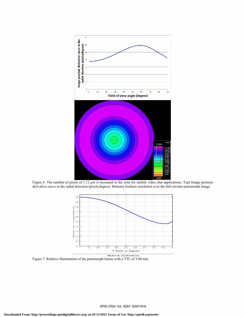
The second miniature panomorph lens was designed at the end of 2013 for mobile device applications. The main requirement was a smaller TTL and diameter. The design starting point was the previous 6.56 mm lens where the two non-rotationally symmetric surfaces were converted back to symmetric in order to miniaturize the lens. The resulting design achieved a TTL of 3.80 mm including a 0.2 mm cover glass (3.72 mm in air). As shown at figure 5, the layout still consist of 6 plastic elements, the shorter TTL being obtained by further compressing every air spaces and lens thickness to their manufacturing limits and placing the IR filter on the sensor cover glass. This f/2.8 lens has a 1:1 anamorphic ratio and use targeted distortion to increase the number of pixels in the zone of interest for mobile video chat applications as shown at figure 6. While defining the distortion profile ratio from minimum to maximum number of pixels/degree, special care was given to make sure the lateral color of the resulting lens remain negligible. The panomorph footprint is 2.01 x 2.01 mm and is designed for the full 360° image to fit the height on a 5.04 MPx 4:3 sensor with 2592 x 1944 pixels of 1.12 µm. The resulting number of effective pixels inside the elliptical panomorph image is 2.53 MPx. Figure 7 shows the relative illumination of this lens.
Figure 5. Layout of a panomorph lenses with a TTL of 3.80 mm using the same scale as figure 2. Not shown on the image is the 0.20 mm cover glass of the sensor which is included in the TTL measurement of 3.80 mm.
SPIE-OSA/ Vol. 9293 92931N-5
Downloaded From: http://proceedings.spiedigitallibrary.org/ on 01/12/2015 Terms of Use: http://spiedl.org/terms
O
Imag
e po
sitio
n de
rivat
ive
curv
e in
the
radi
al d
irect
ion
(pix
els
/deg
ree)
rA
tT
O>
OÑ
A
9!1 1L2 27.9 96.4 45.5 54.6 69.7 723 61.2 21
Y Field in Degrees
Relative Illumination
Figure 6. The number of pixels of 1.12 µm is increased in the zone for mobile video chat applications. Top) Image position derivative curve in the radial direction (pixels/degree). Bottom) Surfacic resolution over the full circular panomorph image.
Figure 7. Relative illumination of the panomorph lenses with a TTL of 3.80 mm.
SPIE-OSA/ Vol. 9293 92931N-6
Downloaded From: http://proceedings.spiedigitallibrary.org/ on 01/12/2015 Terms of Use: http://spiedl.org/terms

3 3
5.85mm
3.25mm
5. ASSEMBLED LENSES PERFORMANCES AND IMAGES
Prototypes samples were built from both miniatures panomorph design theoretically presented at sections 3 and 4. The outside appearance of these lenses as well as their mechanical lengths and diameters are shown at figure 8. Some example captured images from these two panomorph lenses in a video chat configuration are shown at figure 9. For these images, default sensor settings are used and some specific lens/sensor tuning could improve even further the picture quality and color fidelity. Also, low-cost prototype molds were used at this stage and tighter manufacturing accuracy with mass production molds will further improve stability and quality.
Figure 8. Pictures of samples lenses for both panomorph lenses. Left) The lens with a TTL of 6.56 mm has a mechanical length of 5.85 mm and a mechanical diameter of 12.8 mm. Right) The lens with a TTL of 3.80 mm has a mechanical length of 3.25 mm and a mechanical diameter of 6.5 mm.
Figure 9. Sample images captured from both panomorph lenses. Left) The lens with a TTL of 6.56 mm captured on a 2MPx sensor. Right) The lens with a TTL of 3.80 mm captured on a 3MPx sensor.
To measure experimentally the distortion and the FoV of these lenses, pictures were taken using a testing setup for panoramic lenses [10]. The targets consist of alternating black and white rectangles each 2° wide as seen from the center of curvature of the cylindrical setup where the lens is located. Figure 10 and figure 11 show the captured image of the calibration targets for respectively the 6.56 mm and the 3.80 mm lenses as well as their resulting departure from the theoretical position in pixels of respectively 1.75 µm and 1.12 µm. In both cases, real lenses image position curves are well within ± 5 pixels of the theoretical calibration curve, allowing to do perfect software de-warping of the image to correct the distortion as discussed in the next section.
SPIE-OSA/ Vol. 9293 92931N-7
Downloaded From: http://proceedings.spiedigitallibrary.org/ on 01/12/2015 Terms of Use: http://spiedl.org/terms

COrtoiOa
,Vo
iV ^N ri _s _'. :lÇ O 0.*:ZO.20 i0 . .5.0 :=$6.0. 70= 80 90
O 41¡
x ... .GJ
0.--L..1LmO. 4wC
6
Field of view angle (degree)
Dep
artu
re fr
om th
eore
tical
pos
ition
(pix
els
of 1
.12p
m)
ó- ó 8 ó ó ó 8
Figure 10. Using the 6.56 mm lens, Top) Captured image strips in the long (red) and short (blue) axis from panoramic testing targets. Bottom) Departure, measured in pixels of 1.75 µm, in both the long (red) and short (blue) axis from the theoretical position relative to the center at 0° for each 2° wide target.
Figure 11. Using the 3.80 mm lens, Top) Captured image strip from panoramic testing targets. Bottom) Departure, measured in pixels of 1.12 µm, from the theoretical position relative to the center at 0° for each 2° wide target.
SPIE-OSA/ Vol. 9293 92931N-8
Downloaded From: http://proceedings.spiedigitallibrary.org/ on 01/12/2015 Terms of Use: http://spiedl.org/terms

6. 360° VISUALISATION AND DE-WARPING ALGORITHMS The role of the de-warping is to exploit the increase of resolution in a region of interest created by the panomorph lens design while removing the distortion to provide human brain friendly views tailored for specific applications or use cases. Panomorph lenses and associated dewarping techniques can be used in many applications such as surveillance, vehicle surround view, photography, robot vision, endoscopy, camcorder and sport cam. In consumer electronic and mobile device fields, the main use cases are 360° live video chat as shown at figure 12 and selfies as shown at figure 13. In this last example, de-warping is also used to correct the viewpoint to a vertical orientation based on orientation information extracted directly from the device, hence the black lower corners.
Figure 12. Software de-warping example using the 3.80 mm lens in the context of video chat. © ImmerVision
Figure 13. Software de-warping example using the 3.80 mm lens in the context of a selfie photograph. In this example, de-warping also adjust the horizon based on the orientation of the device. © ImmerVision
7. CONCLUSION This paper introduced the two smallest panomorph wide-angle lenses with fields of view of 180°. While the lens with optimal sensor coverage using an anamorphic ratio has a TTL of 6.56 mm, the lens with only targeted distortion to increase the number of pixel in the area of interest reach a TTL of 3.80 mm. Following the successful sampling phase for these two lenses, further improvement of these miniature panomorph designs with mass production in mind is currently in progress. These new lenses will have larger apertures and are targeted for sensors with larger megapixels count. Another goal for the next generation of miniature panomorph lens is achieving even smaller size by reducing the number of element and by using new manufacturing techniques allowing smaller edge and central thickness.
SPIE-OSA/ Vol. 9293 92931N-9
Downloaded From: http://proceedings.spiedigitallibrary.org/ on 01/12/2015 Terms of Use: http://spiedl.org/terms

REFERENCES [1] J. Bareau and P. P. Clark, “The optics of miniature digital camera modules,” Proc. SPIE 6342, International Optical Design Conference, 63421F (2006). [2] R. Bates, “Performance and tolerance sensitivity optimization of highly aspheric miniature camera lenses,” Proc. SPIE 7793, Optical System Alignment, Tolerancing, and Verification IV, 779302 (2010). [3] C. Moustier and B. Blanc, “Method for capturing a panoramic image by means of an image sensor rectangular in shape,” US Patent 6,865,028 B2, Foreign application priority 2001, (2005). [4] J-C. Artonne, C. Moustier and B. Blanc, “Method for capturing and displaying a variable resolution digital panoramic image,” US Patent 6,844,990 B2, Foreign application priority 2001, (2005). [5] S. Thibault, “Distortion control offers optical system design a new degree of freedom,” Photonics Spectra, 80-82, (May 2005). [6] M. Villegas, P. Sergerie, and S. Thibault, “Panomorph for smartphones & tablets: the panomorph technology,” ImmerVision Lab, White Paper. https://www.immervisionenables.com/panomorph-technology/resources/, (2011). [7] S.E. Chen, “QuickTime VR: an image-based approach to virtual environment,” Proceedings of the 22nd annual conference on Computer graphics and interactive techniques, 29-38 (1995). [8] S. Thibault, P. Konen, P. Roulet and M. Villegas, “Novel hemispheric image formation: concepts and applications,” Proc. SPIE 6994, Photon Management III, 699406 (2008). [9] J. P. McGuire and T. G. Kuper, “Approaching direct optimization of as-build lens performance,” Proc. SPIE 8487, Novel Optical Systems Design and Optimization XV, 84870D (2012). [10] A-S. Poulin-Girard, J. Parent, S. Thibault and P. Désaulniers, “Dedicated testing setup for panoramic lenses,” Proc. SPIE 7786, Current Developments in Lens Design and Optical Engineering XI, 77860W (2010).
SPIE-OSA/ Vol. 9293 92931N-10
Downloaded From: http://proceedings.spiedigitallibrary.org/ on 01/12/2015 Terms of Use: http://spiedl.org/terms