design decomposition for selecting an electric arc furnace ... · pdf filedesign decomposition...
TRANSCRIPT

Procedia CIRP 34 ( 2015 ) 143 – 149
Available online at www.sciencedirect.com
2212-8271 © 2015 The Authors. Published by Elsevier B.V. This is an open access article under the CC BY-NC-ND license (http://creativecommons.org/licenses/by-nc-nd/4.0/).Peer-review under responsibility of the organizing committee of 9th International Conference on Axiomatic Designdoi: 10.1016/j.procir.2015.08.009
ScienceDirect
9th International Conference on Axiomatic Design – ICAD 2015
Design decomposition for selecting an electric arc furnace off-gas system for SDI Butler flat roll division
A. J. Spencera and D. S. Cochranb,* aSteel Dynamics Inc. Butler Flat Roll Division, 4500 County Road 59, Butler, IN 46721, USA
b Indiana University Purdue University Fort Wayne, 2101 E. Coliseum Blvd, Fort Wayne, IN, 46805, USA
* Corresponding author. Tel.: +1-260-481-6381; E-mail address: [email protected]
Abstract
This paper illustrates how systems requirements (i.e., safety) are decomposed to define manufacturing process requirements and design. Steelmaking is an energy intensive process; utilizing vast amounts of electricity, oxygen, and natural gas to liquefy scrap steel. While the electric arc furnace process is used extensively around the world to melt steel, it is inefficient. Hot gases are lost to fume collection systems and not reused in other parts of the process. Unknown water leaks inside a furnace can potentially result in catastrophic explosions which can injure personnel or damage equipment. Carbon monoxide (CO), the largest gas by product of steelmaking, has caused several large scale explosions globally resulting in large repair bills. A system to not only detect gases present in the gas steam exiting the furnace but to quantify the amounts being produced can lead to ensuring the furnaces are safer for employees to work around. This paper will break down the decision process in selecting the hybrid probe-laser off-gas system by means of axiomatic design decomposition at an American mini-mill located in Butler, Indiana using the Collective System Design (CSD) methodology utilized at IPFW Center of Excellence in Systems Engineering. © 2015 The Authors. Published by Elsevier B.V. Peer-review under responsibility of the organizing committee of 9th International Conference on Axiomatic Design.
Keywords: Collective system design; off-gas analysis; safety
1. Collective system design methodology
Conventional systems engineering tools act as a tool box; where these tools can be applied to any system. While these tools are beneficial they often lack the real world usefulness when being used in a work environment. The Collective System Design has been developed and being fine-tuned at the IPFW Center of Excellence in Fort Wayne, Indiana. The research presented in this paper utilizes the CSD model to integrate theory and practice into a business decision recently finalized by an American steel company, Steel Dynamics Inc.
The IPFW Center of Excellence was developed to educate students and work with industry in the northeast Indiana area to develop, sustain and grow their business in a manufacturing rich environment. The CSD model can be broken down into a framework of five parts [1,2]: (1) the flame model, (2) CSD language, (3) CSD design map, (4) standard work and (5) PDCA learning loop. These five parts cumulate into a
decomposed process map for industry decision called the Manufacturing System Design Decomposition.
Nomenclature CSD collective system design IPFW Indiana-Purdue Fort Wayne University SDI Steel Dynamics Inc. MSDD manufacturing system design decomposition FR functional requirement PS physical solution FRm function requirement metric PSm physical solution metric PDCA plan-do-check-act MW/min Megawatt per minute CO carbon monoxide CO2 carbon dioxide CH4 natural gas
© 2015 The Authors. Published by Elsevier B.V. This is an open access article under the CC BY-NC-ND license (http://creativecommons.org/licenses/by-nc-nd/4.0/).Peer-review under responsibility of the organizing committee of 9th International Conference on Axiomatic Design
144 A.J. Spencer and D. S. Cochran / Procedia CIRP 34 ( 2015 ) 143 – 149
1.1. The flame model
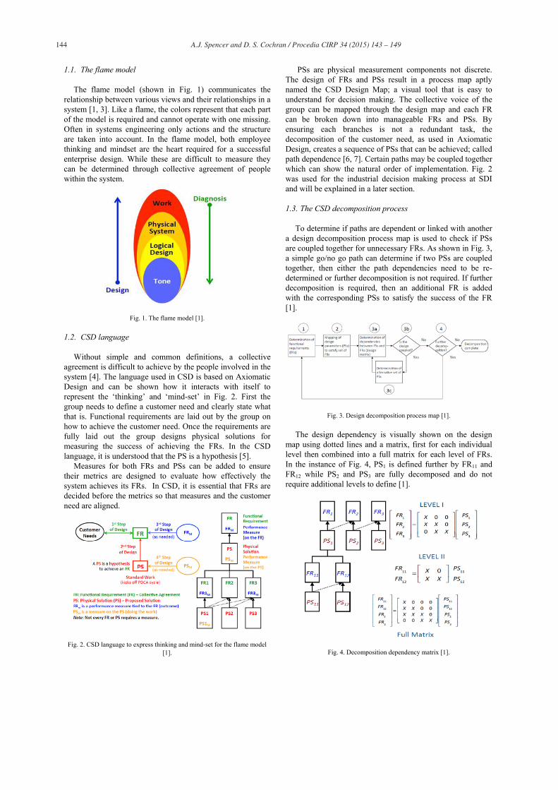
The flame model (shown in Fig. 1) communicates the relationship between various views and their relationships in a system [1, 3]. Like a flame, the colors represent that each part of the model is required and cannot operate with one missing. Often in systems engineering only actions and the structure are taken into account. In the flame model, both employee thinking and mindset are the heart required for a successful enterprise design. While these are difficult to measure they can be determined through collective agreement of people within the system.
Fig. 1. The flame model [1].
1.2. CSD language
Without simple and common definitions, a collective agreement is difficult to achieve by the people involved in the system [4]. The language used in CSD is based on Axiomatic Design and can be shown how it interacts with itself to represent the ‘thinking’ and ‘mind-set’ in Fig. 2. First the group needs to define a customer need and clearly state what that is. Functional requirements are laid out by the group on how to achieve the customer need. Once the requirements are fully laid out the group designs physical solutions for measuring the success of achieving the FRs. In the CSD language, it is understood that the PS is a hypothesis [5].
Measures for both FRs and PSs can be added to ensure their metrics are designed to evaluate how effectively the system achieves its FRs. In CSD, it is essential that FRs are decided before the metrics so that measures and the customer need are aligned.
Fig. 2. CSD language to express thinking and mind-set for the flame model [1].
PSs are physical measurement components not discrete. The design of FRs and PSs result in a process map aptly named the CSD Design Map; a visual tool that is easy to understand for decision making. The collective voice of the group can be mapped through the design map and each FR can be broken down into manageable FRs and PSs. By ensuring each branches is not a redundant task, the decomposition of the customer need, as used in Axiomatic Design, creates a sequence of PSs that can be achieved; called path dependence [6, 7]. Certain paths may be coupled together which can show the natural order of implementation. Fig. 2 was used for the industrial decision making process at SDI and will be explained in a later section.
1.3. The CSD decomposition process
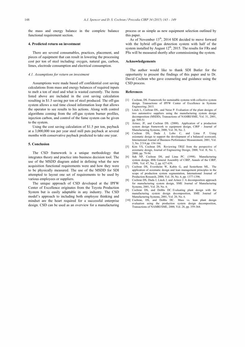
To determine if paths are dependent or linked with another a design decomposition process map is used to check if PSs are coupled together for unnecessary FRs. As shown in Fig. 3, a simple go/no go path can determine if two PSs are coupled together, then either the path dependencies need to be re-determined or further decomposition is not required. If further decomposition is required, then an additional FR is added with the corresponding PSs to satisfy the success of the FR [1].
Fig. 3. Design decomposition process map [1].
The design dependency is visually shown on the design map using dotted lines and a matrix, first for each individual level then combined into a full matrix for each level of FRs. In the instance of Fig. 4, PS1 is defined further by FR11 and FR12 while PS2 and PS3 are fully decomposed and do not require additional levels to define [1].
Fig. 4. Decomposition dependency matrix [1].

145 A.J. Spencer and D. S. Cochran / Procedia CIRP 34 ( 2015 ) 143 – 149
1.4. Plan-Do-Check-Act loop
Each PS is treated as a hypothesis; a small experiment needed to complete a large experiment. So that each PS has as few variables as possible, standard work is defined so that each PS is repeatable with timing and sequencing laid out [1, 8, 9, 10]. The PDCA loop detects shortcomings and failings for path dependencies and is constantly adapting changes needed for the system through the process of a PS hypothesis, implementing the PS, checking the results using an FRm or PSm and finally acting if change is needed. The PDCA is tied in with white and green sheet work as shown in Fig. 5.
Fig. 5. PDCA loop with standard work linked to the CSD map [1].
1.5. Standard work
Standard work is defined by the FR and PS in the planning step. Typical work (white sheet work) is performed as a routine by employees and tested using the FRm and PSm to ensure the FR and PS are being completed as planned [1, 8]. If non routine work (abnormal work) is encountered then change is needed to the FR and PS (green sheet work). This green sheet work requires new planning to ensure the FR and PS are met and new white sheet work is implemented. This PDCA cycle is a continuous improvement loop; changing as change is encountered or required [1].
2. Use of CSD at Steel Dynamics
Using the five steps outlined by CSD, a design maps can be used by companies to improve their overall process flow or broken down for individual parts of their system. The CSD MSDD was used at SDI in the autumn of 2014 for a decision making process that resulted in the purchase of a new $1.6 million system to operate at its furnaces. This system is used to detect, provide feedback and make changes in the furnace based off gases being emitted from the furnace. Using the MSDD, the customer (SDI) laid out the requirements it wanted and presented the results to the three companies who responded to a request for tender. After negotiations, the supplier that was chosen met the needs of each FR and PS shown in Fig. 6. Information that is sensitive to SDI has been left out of the report such as competing suppliers, certain furnace information and return on investment calculations.
2.1. Off-gas role in steelmaking
The role of off-gas in steelmaking processes is of great importance for the production and refinement of the melting process. The gas stream leaving the furnace is a representation of how efficient the melting process is and when additions should be added. The off-gases can indicate whether a water leak is present in the water cooled panels that prevent molten steel from splashing onto the working deck of employees. The off-gases can also predict if large buildups of CO are not combusting to CO2, which can lead to detrimental equipment explosions downstream. An off-gas detection system can accurately detect water leaks, un-combusted CO, show immediate results from a change, and streamline the melting process.
2.2. Electric arc melting process
Two types of steelmaking exist: integrated steelmaking where iron ore is reduced using a blast furnace and then further processed into steel; and non-integrated steelmaking which typically uses an electric arc furnace to re-melt scrap steel. The process involves layering a steel vessel with types of scrap steel and limes critical to creating a slag layer used to purify the molten metal. The contents are emptied into a furnace shell and graphite electrodes arcs electrical energy (1.5MW/min) directly into the scrap casing it to melt. Burners built into the side of the water cooled furnace shell combust natural gas and oxygen at supersonic speeds through the top slag into the steel accelerating the melting process. Injecting carbon through the burners cause a chemical reaction to occur as shown in Eq (1).
(1)
The gas formed bubbles causing the slag to foam helping stabilize the arc and improving the electrical energy delivered into the steel. Once a specific carbon content and temperature are reached in the steel, the entire furnace tilts back and empties the steel into a refractory lined ladle. The ladle of molten steel is taken for additional processing before being cast and rolled into a finished product. After the heat is tapped, the furnace is rocked back filled with new scrap steel and the process is repeated.
2.3. Off-gas system theory
Off-gas detection is not a new technology, it has existed for several years but the real time feedback from inside the gas stream is new in the past five years. There are three main off-gas styles available in the market today: extractive probe, in situ laser, and hybrid probe/laser. The specified mill is looking primarily for a real time water detection but to also give real time feedback of the gases being produced which can result in making the furnaces more efficient.
2.3.1. Extractive probe off-gas system The extractive probe design extracts an off-gas sample
from the duct work, transports it to an analysis laboratory and

146 A.J. Spencer and D. S. Cochran / Procedia CIRP 34 ( 2015 ) 143 – 149
returns the results of the analysis. The extractive probe returns information, but not in a real time situation but is a well know and dependable process. The laboratory is a wet lab with various scrubbers and detectors. Change over procedures require the furnace to be offline for several dozen minutes.
2.3.2. In situ laser off-gas system A laser emitting diode is installed on one side of the duct
work with a detector on the opposing side. A powerful current is sent to the laser which powers several lasers, each laser detecting a specific type of gas. The laser is aligned so that the laser is directed through the center of the gas stream. Lasers with different wave lengths are used to detect different components of the off-gas stream and information is sent via a fiber optic cable to the control computer in seconds. Change over procedures require the furnace to be offline for several dozen minutes.
2.3.3. Hybrid probe-laser off-gas system The hybrid system uses both an extractive probe and lasers.
A gas sample is extracted from the duct work then through various lasers to detect the components in the off-gas system. Information is sent back to the control computer using fiber optic cable where it determines what is occurring inside the furnace in seconds. Each part of the system has been modularized so that changeover time requires minutes.
3. Manufacturing system design decomposition
The complete MSDD for selecting an off-gas system according to SDI is shown in Appendix A. The MSDD has been broken down into five main categories including: safety improvements, water detection, closing of mass balances, reduction in processing time, and reduction in consumable. The listed topics have been used in the section process for an off-gas system for management at SDI. These five topics will be discussed and further explained in the following sections. In the steel industry the main goal of any project is to either: eliminate safety concerns or make steel cheaper without reducing quality. The main functional requirement combines both cheaper and safer steel using an off-gas system. If the system improves both mentioned issues then the system is successful.
3.1. MSDD safety improvements
The first requirement is for an improvement to the SDI monthly safety record. An off-gas measuring system should give insight to what cannot be seen or measured inside a furnace at 1650 C. First a baseline will be created of previous monthly records to compare once the system is installed and working properly. The safety topics include: detecting enough water inside a furnace that requires it to shut down, give employees advanced warning of leaks, and ensure employees are not around a potential leaking water bomb.
The water detection will be detected by the off-gas system and display warnings to employees on the control computer using a moving point algorithm. The algorithm will be setup to determine how much water ‘typically’ goes into the furnace
during the length of a heat. The moving point algorithm should determine water increases and determine when an abnormal amount of water starts appearing in the gas stream leaving the furnace.
When water goes underneath molten steel, it vaporizes quickly causing the water to expand quickly. Steel cannot move as quickly as water vapor, causing the steam to push the molten metal out of the way so that the steam can escape. A plume of steel is shot out in all directions which is a dangerous safety concern for employees.
3.2. MSDD water detection
Explosions caused by water leaks vaporizing can be catastrophic in the steel industry. A working system has the following FRs: detection of 40 liters per minute (lpm) leak, detect the difference between normality and leak conditions, detect with <1% failure rate, and detect consistently.
The 40 lpm will be determined after testing the gas with added water in the furnace. Additional water will be sprayed into the furnace at known amounts to give a baseline of water additions into the furnace. Based off the water leak test, hydrogen vapor and water vapor will be measured to determine if a water leak is present. Spikes in either are a direct result of added water into the furnace. By measuring the gas throughout the heat, the algorithm changes depending on how much total water is detected and burned off. Determining the difference between a false reading and an actual water leak is another physical solution in determining if a water detection system is working correctly. If the system is warning workers without a proper warning, actual water leak warnings might be ignored by furnace operators. If the system is initially not reliable but improves over time, then the system can be considered to be operating correctly. Finally, the system needs to consistently detect leaks. This will happen if the machine is working properly, is maintained, and continually improved. The system can be monitored for several months by visually inspecting the furnace after each heat for dark spots. A dark spot indicates cold areas caused by water leaks. If water leaks are detected and there are severe dark spots, then it is operating correctly.
3.3. MSDD closing mass-energy balances
By completing the balances inside the furnace, process information can be altered and the effects of a change can be understood. For instance, blowing additional oxygen into a furnace may produce a desired effect but be detrimental elsewhere and not noticed. Making steel is energy intensive and roughly 65% of the energy put into melting the steel stays with the steel, the rest is lost to the furnace water panels, slag, and the off-gas. By measuring the gas, a significant portion of the energy leaving the furnace is known. The known energy going into a furnace comes from electrical power and chemical power. Electrical power is delivered through graphite electrodes directly into the steel. The energy delivered into the furnace equals the energy leaving the furnace as shown in Eq. 2. A large portion of the out energy leaves in the off-gas.

147 A.J. Spencer and D. S. Cochran / Procedia CIRP 34 ( 2015 ) 143 – 149
Chemical energy is delivered from combusting natural gas (Eq. 3), from oxidizing metals (Eq. 4), oxidizing carbon with oxygen (Eq. 1), and combusting the CO gas inside a furnace (Eq. 5).
Finding how and where energy is leaving the furnace is the
first step in making the overall process more efficient. An energy balance can be determined for each heat while it is being made. Several variables are needed to accurately calculate an energy balance: electrical power, oxygen, natural gas, injection carbon amount, charge carbon amount, a steel chemistry, a slag chemistry, temperature of the water leaving the furnace shell, temperature of the water leaving the duct work, temperature of the steel, temperature of the slag, temperature of the furnace refractory before and after, and temperature of the off gas. The calculated value can be compared to the values gathered by the off-gas system. Using the data from the off-gas, a better understanding of the energy balance can be understood leading to making the furnace more efficient.
Next, by completing the mass balance, the process can additionally be improved. The amount of material going into the furnace is recorded for every heat produced and scrutinized on a daily basis. The amount of slag taken per heat is recorded and examined. The amount of steel tapped per heat is closely watched. Carbon blown into the furnace and lost to the off-gas is common but the amount lost has never been measured. It is known that a significant amount of material is lost per heat this way but has never been quantified. The mass balance can be finalized once unknown values are determined from the off-gas system.
Once both balances are completed consumable addition times and amounts can be varied to improve the energy and mass balances, making the overall process more efficient. Baseline results will be measured so that future trials can be compared to see about overall improved efficiency and cost reduction.
3.4. MSDD processing reduction time
Processing time refers to the amount of time required to process one heat of steel, the time from tapping one heat until you tap the next heat. The breakdown of time is closely monitored. Future improvements will be based off current and historic baselines for processing time on a daily, weekly, and monthly time frame. Processing time can benefit in three areas from an off-gas system: tap to tap time, power on time, and improvement in scrap pre-heating. The tap to tap time can be reduced if the scrap can melt quicker or more efficient that
current practice. Burner gas ratios and placement have a direct effect on how much scrap melts around the shell of the furnace. Being able to monitor real time changes will improve the burner melting profiles from current setup. The injection of carbon can also be determined when it is absolutely necessary to improve foaming inside the furnace for optimal arc covering, allowing more power to enter the steel. Benefits will include lower costs in gas and electrical bills each month. The bills will be compared against historical trends and a running 12 month average conversion which is used to determine conversion bonuses for all employees.
The off-gas system also provides a harmonics device in the form of a Rogowski coil to measure harmonics coming off the electrodes. This coil can measure the rate of change in current on AC circuits thus giving a feedback of power delivered into the scrap steel. The current power programs are measured by a coil but having additional information tied into a system from the fume system can improve current practice. Determining how to optimize slag volume will allow power programs to run at lower amperages while delivering the same amount of power into the steel. Running lower amperages will lower the monthly power bill and will be inspected on a monthly basis. Finally, scrap pre-heating can reduce the amount of energy required to melt 168 tonnes of scrap steel. Little research has gone into determining optimal scrap preheating practices. Using the off-gas system, a dynamics algorithm will be setup by altering the gas ratios of the burners to optimize heat delivered into the scrap. The gas ratios will be altered on a weekly basis at first until it is optimized for the different seasons. Once a program is setup, the dynamics algorithm will monitor the gases coming off and change to maintain a constant gas stream composition. This will be monitored on a weekly basis in a reporting system and monthly in the gas bills.
3.5. MSDD consumable reduction
Consumables are closely watched, but furnace operators are allowed to use up to a certain amount per heat. Consumables add to the cost per ton in four main areas: carbon, electrode, oxygen, and fluxes. Consumables are currently measured only on a monthly report, but a program is being written to show a variable time frame report. Carbon is injected and charged with the scrap steel. By understanding the mass and energy balance more, these consumables can hopefully be reduced and will be measured on a heat to heat basis, weekly, and monthly reports. These results will be shown and explained to operators who will in turn attempt to operate at a minimum to reduce overall costs.
Fluxes are broken down into two types of lime, calcined and dolomitic, and are monitored by scales. Once mass balances are completed, reduction in fluxes can start and results will be shared with operators on a daily, weekly, and monthly basis. Oxygen and electrode consumption are measured on a monthly basis from bills and inventory analysis reports. These will both continue to be monitored monthly until a real time report can be created to monitor these consumptions. Oxygen will be altered in the reducing processing time functional requirements and monitored using
148 A.J. Spencer and D. S. Cochran / Procedia CIRP 34 ( 2015 ) 143 – 149
the mass and energy balance in the complete balance functional requirement section.
4. Predicted return on investment
There are several consumables, practices, placement, and pieces of equipment that can result in lowering the processing cost per ton of steel including: oxygen, natural gas, carbon, limes, electrode consumption and electrical consumption.
4.1. Assumptions for return on investment
Assumptions were made based off confidential cost saving calculations from mass and energy balances of required inputs to melt a ton of steel and what is wasted currently. The items listed above are included in the cost saving calculation resulting in $1.5 saving per ton of steel produced. The off-gas system allows a real time closed information loop that allows the operator to see results to his actions. Along with control algorithms coming from the off-gas system burner profiles, injection carbon, and control of the fume system can be given to the system.
Using the cost saving calculation of $1.5 per ton, payback at a 3,000,000 ton per year steel mill puts payback at several months with conservative payback predicted to take one year.
5. Conclusion
The CSD framework is a unique methodology that integrates theory and practice into business decision tool. The use of the MSDD diagram aided in defining what the new acquisition functional requirements were and how they were to be physically measured. The use of the MSDD for SDI attempted to layout one set of requirements to be used by various employees or suppliers.
The unique approach of CSD developed at the IPFW Center of Excellence originates from the Toyota Production System but is easily adaptable in any industry. The CSD model’s approach to including both employee thinking and mindset are the heart required for a successful enterprise design. CSD can be used as an overview for a manufacturing
process or as simple as new equipment selection outlined by this paper.
As of November 13th, 2014 SDI decided to move forward with the hybrid off-gas detection system with half of the system installed by August 12th, 2015. The results for FRs and PSs will be measured shortly after commissioning the system.
Acknowledgements
The author would like to thank SDI Butler for the opportunity to present the findings of this paper and to Dr. David Cochran who gave counseling and guidance using the CSD process.
References
[1] Cochran, DS. Framework for sustainable systems with collective system design. Transactions of IPFW Center of Excellence in Systems Engineering; 2015.
[2] Linck L, Cochran DS., and Neise P. Evaluation of the plant designs of two automotive suppliers using the manufacturing system design decomposition (MSDD), Transactions of NAMRI/SME, Vol. 31, 2001, pp. 509-51
[3] Arinez, JF, and Cochran DS. (2000). Application of a production system design framework to equipment design, CIRP - Journal of Manufacturing Systems, 2000, Vol. 30, No. 2.
[4] Cochran DS, Duda J, Lobo C, and Lima P. Using axiomatic design to support the development of a balanced scorecard, International Journal of Business Performance Measurement, 2001, Vol. 3, No. 2/3/4 pp. 154-166.
[5] Kim YS, Cochran DS. Reviewing TRIZ from the perspective of axiomatic design, Journal of Engineering Design, 2000, Vol. II, No. 1, 2000, pp. 79-94.
[6] Suh NP, Cochran DS, and Lima PC. (1998). Manufacturing system design, 48th General Assembly of CIRP, Annals of the CIRP, 1998, Vol. 47, No. 2, pp. 627-639.
[7] Cochran DS, Eversheim W, Kubin G, and Sesterhenn ML. The application of axiomatic design and lean management principles in the scope of production system segmentation, International Journal of Production Research, 2000, Vol. 38, No. 6, pp. 1377-1396.
[8] Cochran DS, Duda J, Linck J, and Arinez J. A decomposition approach for manufacturing system design, SME Journal of Manufacturing Systems, 2001, Vol. 20, No. 6.
[9] Cochran DS, and Dobbs DC. Evaluating plant design with the manufacturing system design decomposition, SME Journal of Manufacturing Systems, 2001, Vol. 20, No. 6.
[10] Cochran, DS, and Dobbs DC. Mass vs. lean plant design evaluation using the production system design decomposition, Transactions of NAMRI/SME, 2000, Vol. 28, pp. 359-364.

149 A.J. Spencer and D. S. Cochran / Procedia CIRP 34 ( 2015 ) 143 – 149
Appendix A. MSDD of off-gas analysis system at SDI