design & construction of p&l railway bridge … · design & construction of p&l...
TRANSCRIPT
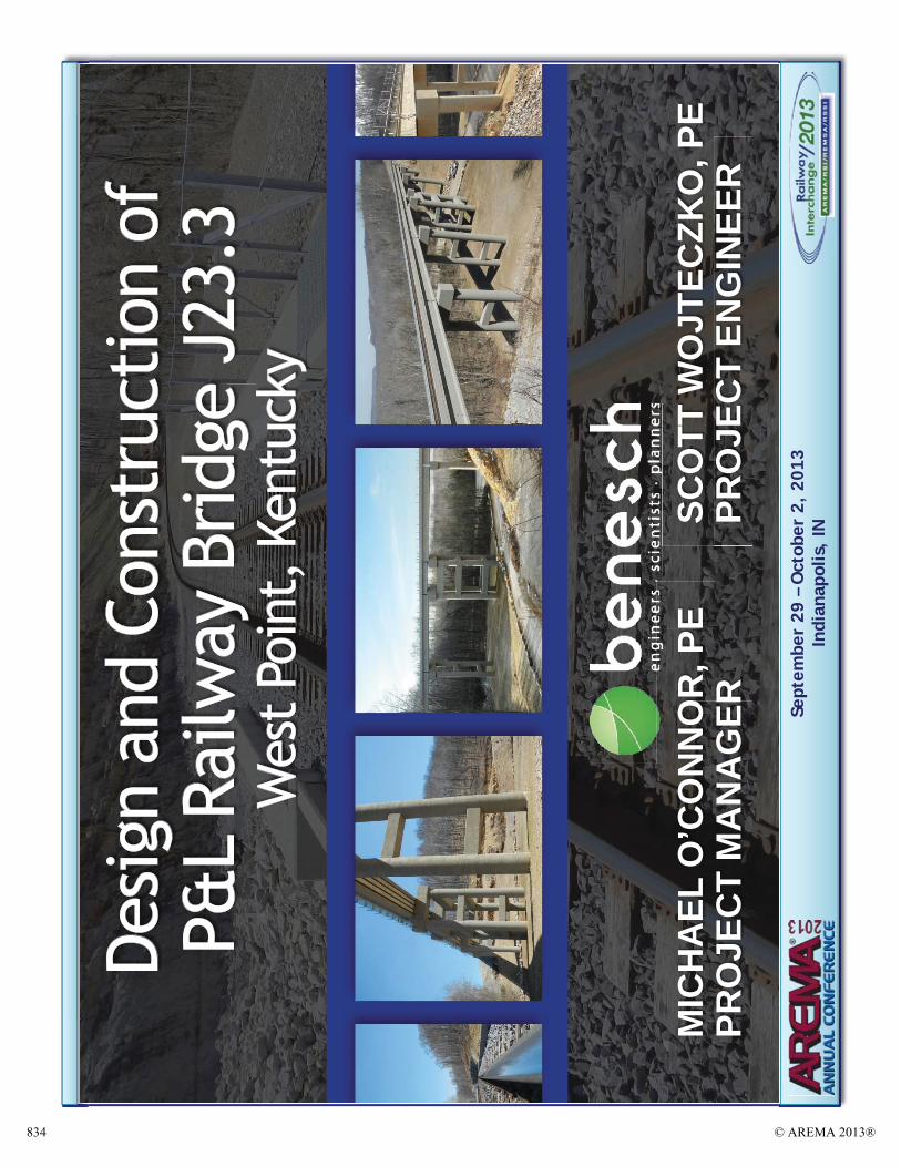
DESIGN & CONSTRUCTION OF P&L RAILWAY BRIDGE J23.3 – WEST POINT, KENTUCKY
AUTHORS:
Michael J. O’Connor, P.E.Alfred Benesch & Company
205 N. Michigan Ave., Suite 2400Chicago, IL 60601P: (312) 565-0450
Scott C. Wojteczko, P.E.Alfred Benesch & Company
205 N. Michigan Ave., Suite 2400Chicago, IL 60601P: (312) 565-0450
[email protected](Primary Author)
Submitted to: AREMA 2013 Annual Conference
WORD COUNT
Text: 3,984 words (excludes captions, acknowledgements and list of figures)Figures and Tables: 3,500 words (14 Figures at 250 words per figure)Total: 7,484 words
ABSTRACT Cutting through mountainous terrain along the bluffs of the Ohio River, Paducah & Louisville Railway (P&L) Bridge J23.3 is an 80’ tall, 120 plus year-old steel trestle structure. Just 0.4 miles down the line is Bridge J23.7, similar in size and type. Together, these bridges serve as part of a critical rail connection to the nearby Fort Knox Army Base. With repair costs mounting, the P&L decided to replace both structures, only there was one significant constraint – the bridges could not be taken out of service.
Bridge J23.3 was slated for completion first as part of Phase I of the project, with J23.7 to follow at an unknown time as part of Phase II. Railroad engineers at Alfred Benesch & Company were challenged to develop a solution that would allow for the bridge structure at J23.3 to be replaced on an alignment that could tie into both the existing alignment across the structure at J23.7 as well as the proposed alignment of the future replacement structure at J23.7, all while allowing for continuous rail operations throughout construction of the new structures.
The design team analyzed multiple corridor alignment alternatives that could meet the complex project constraints. The most efficient and economical solution was determined to be building both Bridges J23.3 and J23.7 on an offset alignment, with less than 30’ offset between the existing and proposed track centers at J23.3. Realignment would allow for a safer and more efficient construction process, as construction activities would be focused outside of live rail traffic.
© AREMA 2013® 817
This paper will examine how the design team pushed the limits of typical rail construction at Bridge J23.3 to minimize both the project costs and environmental impacts associated with realignment. Creativity coupled with skillful engineering resulted in a successful solution to acomplex railroad bridge replacement project.
INTRODUCTION
Paducah and Louisville (P&L) Railway bridges J23.3 and J23.7 are located in West Point,Kentucky, adjacent to the Fort Knox military complex. Alfred Benesch & Company (Benesch) began inspecting the existing steel trestle structures in the late 1980s. The age and condition ofthe structures had necessitated numerous repairs and strengthening measures over the past 20 plus years to maintain continual rail service.
In 2009, the P&L initiated a two-phase program to replace the two aging structures, with J23.3 scheduled for replacement in Phase I and J23.7 in Phase II (note that this paper will focus on the design and construction for Phase I of the project only). A corridor alignment study was completed to develop a revised rail alignment that would meet the two-phase program requirements. The end solution was to offset the new bridge structures from the existing rail alignment to allow for construction to proceed without any impacts on the existing rail traffic.The new bridge structure at J23.3 was to be 534’ long and 80’ tall, offset less than 30’ from the existing rail alignment.
The primary project team for Phase I included the P&L (owner), Benesch (lead engineer), GEMEngineering (geotechnical subconsultant) and Haydon Bridge Company (general contractor). The project posed numerous complex constraints, both geographic (rocky slopes, narrow corridor) and operational (no rail disruptions). The project team took innovative design measures (i.e. long span highway type PPC-I beams, a central rigid braced pier and irregular bearing fixity) and created a detailed site access plan to overcome these constraints and successfully complete Phase I of the project.
BACKGROUND
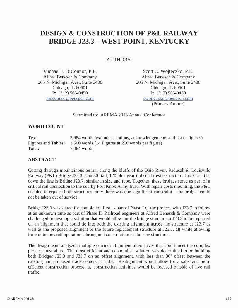
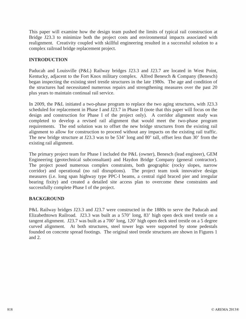
P&L Railway bridges J23.3 and J23.7 were constructed in the 1880s to serve the Paducah and Elizabethtown Railroad. J23.3 was built as a 570’ long, 83’ high open deck steel trestle on a tangent alignment. J23.7 was built as a 700’ long, 120’ high open deck steel trestle on a 5 degree curved alignment. At both structures, steel tower legs were supported by stone pedestals founded on concrete spread footings. The original steel trestle structures are shown in Figures 1 and 2.
© AREMA 2013®818
Figure 1: Original J23.3 Structure
Figure 2: Original (and Existing) J23.7 Structure
© AREMA 2013® 819
Bridge J23.3 crosses the historic Louisville and Nashville (L&N) Turnpike. This roadway was built in the 1830s as the first improved road to provide the area with a route out of the OhioRiver bottomlands. It was closed to public traffic in 1918 after Camp Knox was established due to its proximity to intended artillery ranges.
The P&L Railway is the only railroad providing service to current-day Fort Knox. As such, the section of the railway in and around the army post has been designated as part of the Strategic Rail Corridor Network and as a Defense Connector Line. The military’s reliance on the rail service for quick deployment of military equipment makes it critical that service be maintained at all times.
PROJECT CONSTRAINTS
There were a significant number of constraints identified at the onset of the project that would guide the rail corridor study, structure design and construction plan. These constraints can be split into two primary groups:
Geographic / Topographic ConstraintsOperational Constraints
Geographic / Topographic
The terrain throughout the rail corridor consists of a highly irregular, continuous set of hills.When originally constructed in the 1800s, the railroad was benched into the steep slope of thishillside. For the at-grade portions of the corridor, any realignment on the downhill side of the track would require significant quantities of fill and/or retaining walls; any realignment on the uphill side of the track would require cutting deep into the hillside, with significant quantities of rock blasting and removal required. The extent of fill/removal work was magnified by the fact that existing earth slopes were as steep as 1:1, with vertical rock faces adjacent to the track in certain locations. Figure 3a shows an example of the typically steep rock out-cropping along the tracks between bridges J23.3 and J23.7.
Bridges J23.3 and J23.7 span two significant valleys in the region. Each valley includes a waterway that passes beneath the bridge structures that could not be diverted or modified. The subsurface conditions at the bridge locations are highly irregular, with bedrock elevations often at the surface of the steep valley slopes (see Figure 3b), yet as deep as 40 feet below ground in the main valley.
© AREMA 2013®820

Figures 3a and 3b: Typ. Rocky Terrain at (a) Corridor between Bridges and (b) J23.3 Base
Operational
No significant disruptions to rail operations would be allowed by the P&L during construction. The decision to maintain all rail operations was made both to maintain regularly scheduled freight distributions to all clients along this portion of the line, as well as to allow for immediate usage by Fort Knox in the event of an emergency.
With the project split into two phases, any realignment implemented at J23.3 would have to tie back into the existing alignment before reaching the J23.7 structure. At the time of design, it was unknown how long of a gap would exist between Phase I and Phase II of the project, thus a common tie-in point between the bridges was mandatory.
CORRIDOR STUDY
Whether or not to realign the railroad through the project limits was the most critical decision made during the corridor study. To maintain the existing alignment, new bridge structures would have to be built underneath the existing bridge structures at J23.3 and J23.7. The location and material of the new structures would thus be controlled by the existing steel trestle towers. Additionally, highly coordinated change-outs during rail closures would be required to systematically remove and replace sections of the existing structures. After considering the potential risks associated with in-line construction, the project team came to the conclusion that building new structures on an offset alignment would be the safest, most timely and cost efficient solution.
Realignment at Bridge J23.3 required building the new structure south of the existing structure, on the mountainous side of the region. The extent to which the alignment was offset would have
© AREMA 2013® 821
a direct impact on the amount of hillside to be removed at both ends of J23.3. Due to the shallow bedrock elevations and irregular rock outcroppings, any cuts into the hillside would require controlled rock blasting. To minimize the amount of blasting and the impact on the hillside, the existing alignment was offset by the minimal distance that was anticipated to allow continuous construction without rail disruptions. This offset ended up being approximately 27’ at the east end and 30’ at the west end.
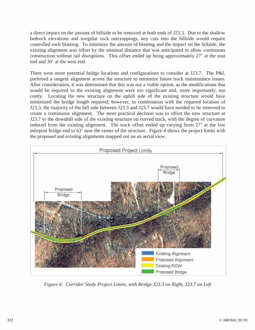
There were more potential bridge locations and configurations to consider at J23.7. The P&L preferred a tangent alignment across the structure to minimize future track maintenance issues. After consideration, it was determined that this was not a viable option, as the modifications that would be required to the existing alignment were too significant and, more importantly, too costly. Locating the new structure on the uphill side of the existing structure would have minimized the bridge length required; however, in combination with the required location of J23.3, the majority of the hill side between J23.3 and J23.7 would have needed to be removed to create a continuous alignment. The most practical decision was to offset the new structure at J23.7 to the downhill side of the existing structure on curved track, with the degree of curvature reduced from the existing alignment. The track offset ended up varying from 27’ at the low milepost bridge end to 63’ near the center of the structure. Figure 4 shows the project limits with the proposed and existing alignments mapped out on an aerial view.
Figure 4: Corridor Study Project Limits, with Bridge J23.3 on Right, J23.7 on Left
© AREMA 2013®822
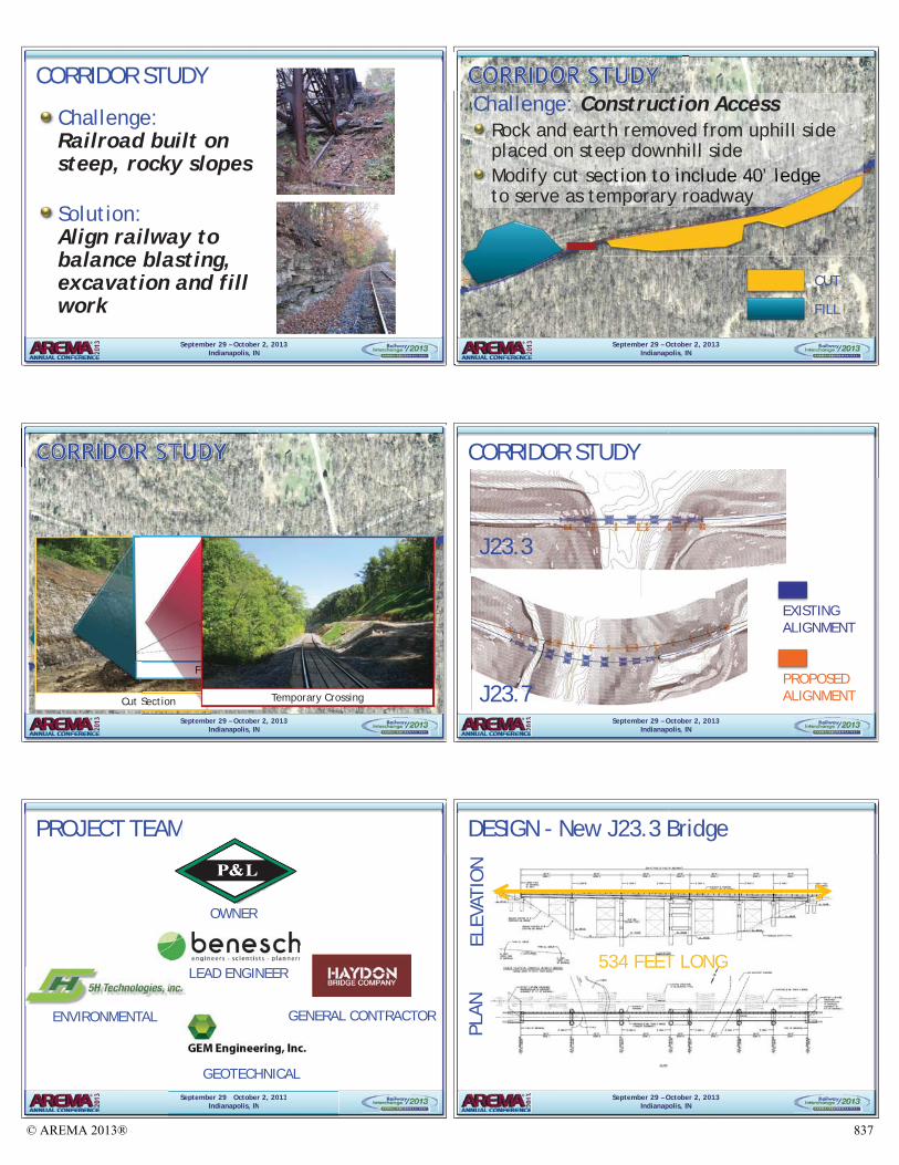
Even with the bridge locations established, significant challenges remained to finalize a revised alignment. For starters, what would be done with the significant amounts of earth and rock being removed from the hillside, and how would the contractor get the necessary construction equipment to the narrow corridor between J23.3 and J23.7? The project team developed a solution that could address both of these problems simultaneously. The large volume of earth and rock removed from the uphill side of the track was placed on the steep downhill side of the track near Bridge J23.7. This built-up fill zone provided a means of access from the bottom of the valley up to track level for construction equipment and haul trucks, as well as a needed construction platform to construct the east end of J23.7.
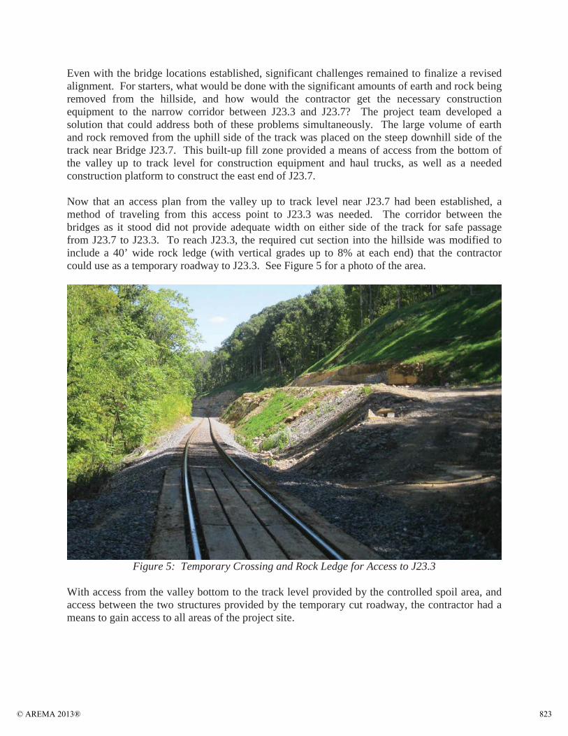
Now that an access plan from the valley up to track level near J23.7 had been established, a method of traveling from this access point to J23.3 was needed. The corridor between the bridges as it stood did not provide adequate width on either side of the track for safe passage from J23.7 to J23.3. To reach J23.3, the required cut section into the hillside was modified to include a 40’ wide rock ledge (with vertical grades up to 8% at each end) that the contractor could use as a temporary roadway to J23.3. See Figure 5 for a photo of the area.
Figure 5: Temporary Crossing and Rock Ledge for Access to J23.3
With access from the valley bottom to the track level provided by the controlled spoil area, and access between the two structures provided by the temporary cut roadway, the contractor had a means to gain access to all areas of the project site.
© AREMA 2013® 823
J23.3 DESIGN FEATURES
With an alignment created that would meet the operational constraints of the railway, the task then fell to the design team to create a bridge design that could fit into the footprint limited by the geographic / topographic constraints of the J23.3 project site. Several unique design features were implemented to meet the project objective and are discussed herein.
Minimal Substructure Footprint
The existing bridge at J23.3 was supported by steel trestle towers, with inclined legs sitting on concrete and stone spread footings. The inclined tower legs and height of the bridge led to a wide placement of tower footings, and thus a potential conflict with the substructure elements of the new bridge foundations. In addition, any new substructure elements could not be located within the limits of Tioga Creek (environmental issues) and the old L&N Turnpike (historic),which both pass beneath the existing structure.
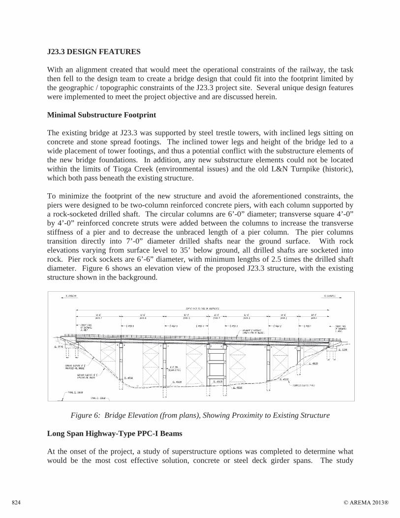
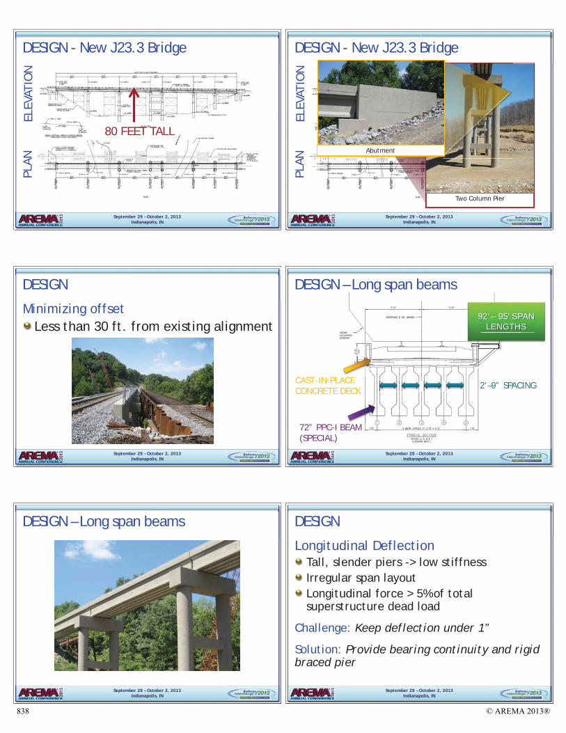
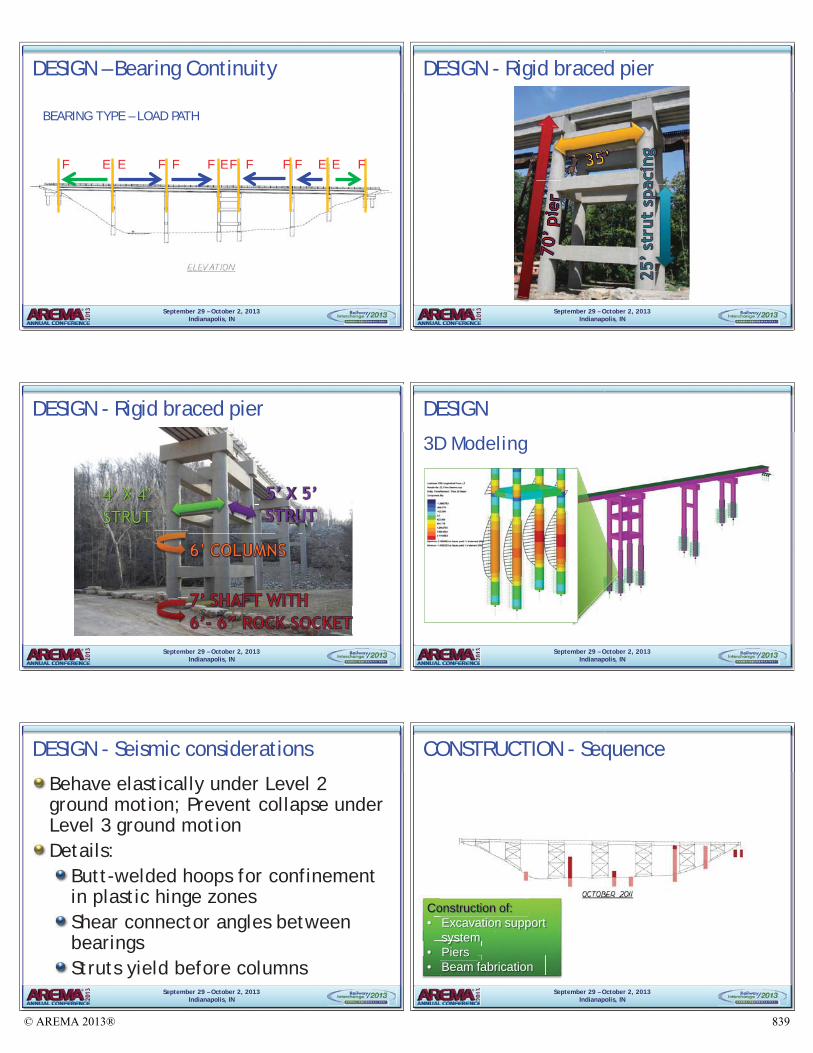
To minimize the footprint of the new structure and avoid the aforementioned constraints, the piers were designed to be two-column reinforced concrete piers, with each column supported by a rock-socketed drilled shaft. The circular columns are 6’-0” diameter; transverse square 4’-0” by 4’-0” reinforced concrete struts were added between the columns to increase the transverse stiffness of a pier and to decrease the unbraced length of a pier column. The pier columns transition directly into 7’-0” diameter drilled shafts near the ground surface. With rock elevations varying from surface level to 35’ below ground, all drilled shafts are socketed into rock. Pier rock sockets are 6’-6” diameter, with minimum lengths of 2.5 times the drilled shaft diameter. Figure 6 shows an elevation view of the proposed J23.3 structure, with the existing structure shown in the background.
Figure 6: Bridge Elevation (from plans), Showing Proximity to Existing Structure
Long Span Highway-Type PPC-I Beams
At the onset of the project, a study of superstructure options was completed to determine what would be the most cost effective solution, concrete or steel deck girder spans. The study
© AREMA 2013®824
considered various span lengths for both materials. The final conclusion was that the most economical option was to use precast, prestressed concrete I-beams (PPC-I beams). Maximizing span lengths would allow for the number of pier units to be minimized, which was essential due to the various foundation constraints.
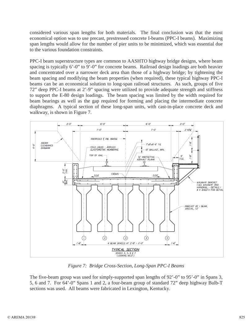
PPC-I beam superstructure types are common to AASHTO highway bridge designs, where beam spacing is typically 6’-0” to 9’-0” for concrete beams. Railroad design loadings are both heavier and concentrated over a narrower deck area than those of a highway bridge; by tightening the beam spacing and modifying the beam properties (when required), these typical highway PPC-Ibeams can be an economical solution to long-span railroad structures. As such, groups of five 72” deep PPC-I beams at 2’-9” spacing were utilized to provide adequate strength and stiffness to support the E-80 design loadings. The beam spacing was limited by the width required for beam bearings as well as the gap required for forming and placing the intermediate concrete diaphragms. A typical section of these long-span units, with cast-in-place concrete deck and walkway, is shown in Figure 7.
Figure 7: Bridge Cross-Section, Long-Span PPC-I Beams
The five-beam group was used for simply-supported span lengths of 92’-0” to 95’-0” in Spans 3, 5, 6 and 7. For 64’-0” Spans 1 and 2, a four-beam group of standard 72” deep highway Bulb-Tsections was used. All beams were fabricated in Lexington, Kentucky.
© AREMA 2013® 825
Rigid Braced Pier 3-4
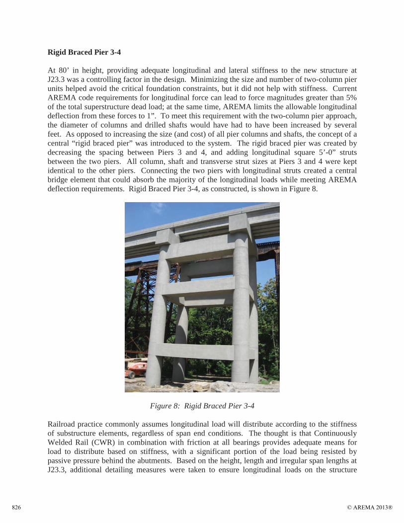
At 80’ in height, providing adequate longitudinal and lateral stiffness to the new structure at J23.3 was a controlling factor in the design. Minimizing the size and number of two-column pier units helped avoid the critical foundation constraints, but it did not help with stiffness. Current AREMA code requirements for longitudinal force can lead to force magnitudes greater than 5% of the total superstructure dead load; at the same time, AREMA limits the allowable longitudinal deflection from these forces to 1”. To meet this requirement with the two-column pier approach, the diameter of columns and drilled shafts would have had to have been increased by several feet. As opposed to increasing the size (and cost) of all pier columns and shafts, the concept of a central “rigid braced pier” was introduced to the system. The rigid braced pier was created by decreasing the spacing between Piers 3 and 4, and adding longitudinal square 5’-0” struts between the two piers. All column, shaft and transverse strut sizes at Piers 3 and 4 were kept identical to the other piers. Connecting the two piers with longitudinal struts created a central bridge element that could absorb the majority of the longitudinal loads while meeting AREMA deflection requirements. Rigid Braced Pier 3-4, as constructed, is shown in Figure 8.
Figure 8: Rigid Braced Pier 3-4
Railroad practice commonly assumes longitudinal load will distribute according to the stiffness of substructure elements, regardless of span end conditions. The thought is that Continuously Welded Rail (CWR) in combination with friction at all bearings provides adequate means for load to distribute based on stiffness, with a significant portion of the load being resisted by passive pressure behind the abutments. Based on the height, length and irregular span lengths at J23.3, additional detailing measures were taken to ensure longitudinal loads on the structure
© AREMA 2013®826
would distribute based on the relative stiffness of the substructure elements, thus ensuring the rigid braced pier would absorb the majority of loads. Spans 3 and 5 were designed as fixed-fixed spans, as opposed to the typical fixed-expansion spans used in railroad design. The introduction of double fixity in these two spans locked the structure together as one unit between Piers 1 and 6. This guarantees uniform pier displacements and prevents tall flexible piers from acting independently and at risk to excessive deflections. The rigid braced pier contributes around 90% of the total longitudinal stiffness in the central bridge unit. Any longitudinal load on the end spans is taken out of the structure at the abutments, where four drilled shafts resist lateral loadingthrough frame action.
Seismic Considerations
P&L Bridge J23.3 is located in an outer ring of the New Madrid Seismic Zone. Seismic analysis and detailing requirements of AREMA Chapter 9 were thoroughly considered in the design of the new structure. Based on the significance of the structure, the project approach was to design J23.3 to behave elastically under Level 2 ground motion and to detail J23.3 to prevent failure under Level 3 ground motion.
AnalysisBridge J23.3 has a multi-span irregular configuration, thus a Modal Analysis procedure was required for seismic consideration. Elastic response spectra were created to define the seismic response amplification at different structural periods. The response spectra were input to LUSAS 3D modeling software, where a multimodal seismic analysis was performed. The program was used to generate the controlling mode shapes and natural frequencies of the structure, which were in turn combined to generate the design seismic loads for all substructure elements.
DetailingAppropriate detailing provisions per AREMA (and supplemented by AASHTO provisions) were incorporated into the structure to meet performance requirements for Level 3 ground motion. The following is a summary of the primary detailing techniques that were implemented to improve ductility and seismic behavior at J23.3:
Butt-welded hoops were used as the confinement reinforcement in all pier columns and shafts, with maximum spacing reduced in plastic hinge zones to meet code requirements.Side retainer angles were detailed between all beam bearings to improve load transfer.CWR is specified across the structure to provide load path redundancy and increase bridge damping.Transverse and longitudinal pier struts were designed to yield prior to column yielding, forcing the initial plastic hinges to form within the secondary strut members.No lapping of vertical reinforcement was allowed in plastic hinge zones (mechanical couplers specified).
© AREMA 2013® 827
LUSAS 3D Modeling
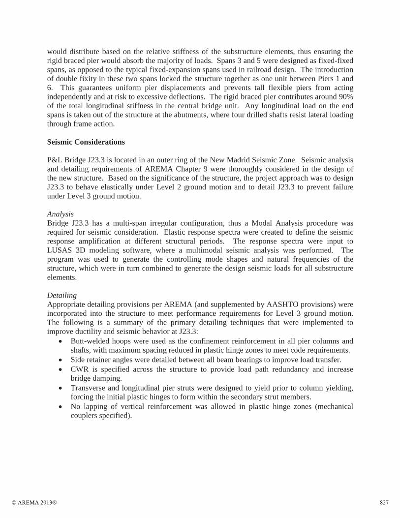
LUSAS 3D modeling software was implemented throughout the design process to consider global structural behavior. As previously mentioned, the global 3D model was used to perform the necessary seismic analyses (see Figure 9 for a model rendering).
Figure 9: LUSAS 3D Model, Isometric View of Bridge J23.3
In addition to seismic analyses, the model was used to estimate longitudinal and transverse pier deflections under loading. Structural models are typically built assuming a point of fixity for all substructure elements, without modeling the soil-structure interaction. The implementation of lateral springs in LUSAS allowed for a full structural model to be created, from the bottom of rock-socket elevation up to the reinforced concrete deck. Subsurface analyses performed using LPILE software was used to determine the appropriate spring stiffness to be used in LUSAS. These spring values were iterated until the resulting pier deflections were matched between the two programs. The models were therefore calibrated to ensure the effective stiffness at each substructure unit was being used in deflection checks.
CONSTRUCTION
Haydon Bridge Company was selected as the general contractor for Phase I of the project. Construction for Phase I began in June of 2011 with a scheduled completion date in August of 2012.
Site Access
Once mobilized, the contractor immediately began developing temporary paths to access critical locations near J23.3 that were otherwise inaccessible (i.e. Piers 1 and 6, to be constructed on the steep valley slopes). These access paths could not extend beyond the right-of-way the P&L had acquired from Fort Knox and/or the temporary easement limits that had been established;
© AREMA 2013®828
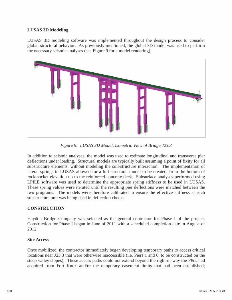
therefore, it was critical that land be used efficiently. Figure 10 shows an aerial view of the J23.3 site taken during the early months of construction.
Figure 10: Aerial View of J23.3 Project Site Early in Construction
Rock Blasting
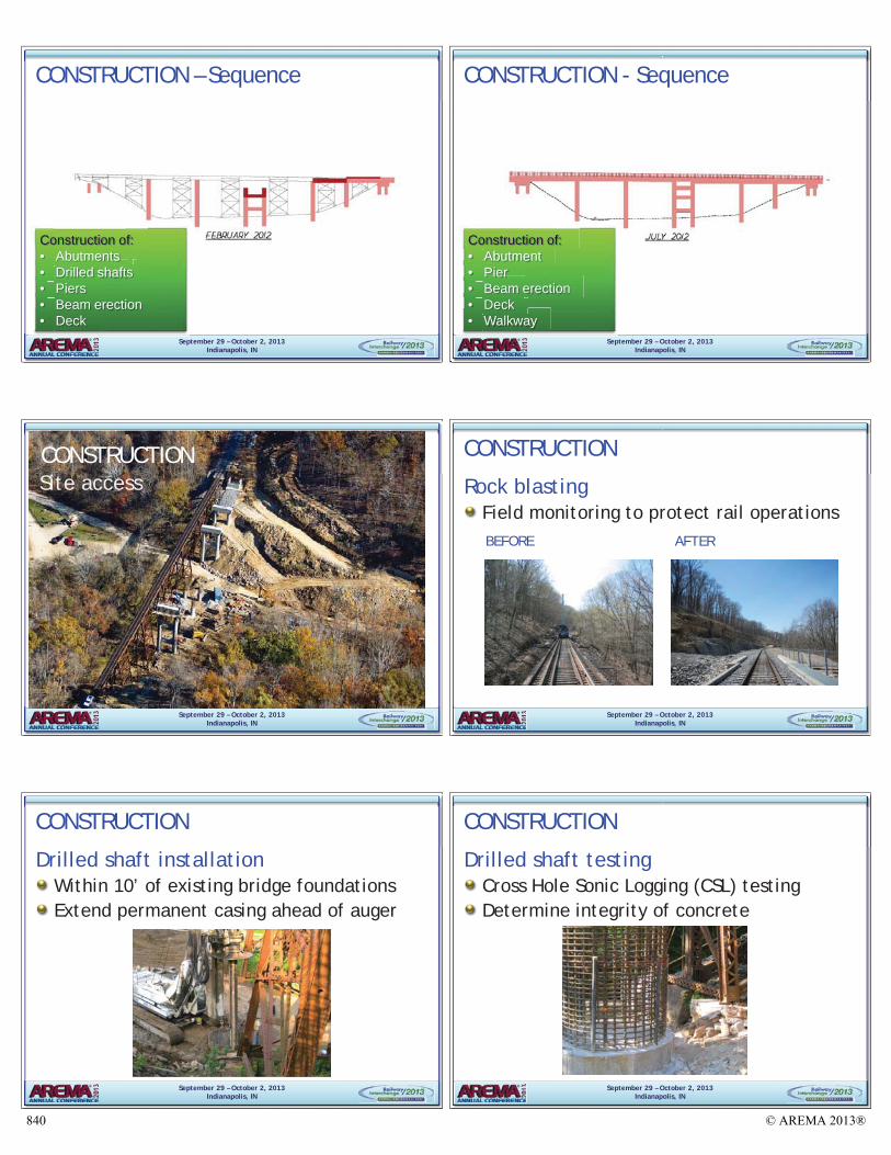
During construction, one of the primary concerns was rock blasting work near live tracks.Several field monitoring requirements were added to the plans and specifications to protect train operations during these activities. During blasting work, the existing track and bridge structures were monitored for movement with field survey. To supplement the field survey at the bridges, seismographs were used for a more precise control method. No issues were reported during construction.
Drilled Shaft Installation
Another primary concern during construction was drilled shaft installation adjacent to the existing J23.3 bridge foundations. Since the new drilled shafts were at times within 10’ of the existing bridge foundations (see Figure 11), the contract plans and specifications included several procedural requirements that impacted the drilled shaft installation plan. First off, the contractor was required to extend a permanent casing ahead of the drilled shaft auger to reduce the risk of undermining the existing footings. Additionally, vibratory head was not allowed. Aswas the case during the rock blasting, the existing footings and track were monitored for movement with field survey and seismographs. No issues were reported during construction.
© AREMA 2013® 829
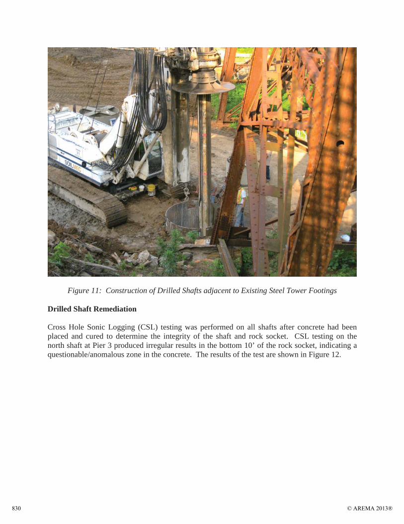
Figure 11: Construction of Drilled Shafts adjacent to Existing Steel Tower Footings
Drilled Shaft Remediation
Cross Hole Sonic Logging (CSL) testing was performed on all shafts after concrete had been placed and cured to determine the integrity of the shaft and rock socket. CSL testing on the north shaft at Pier 3 produced irregular results in the bottom 10’ of the rock socket, indicating a questionable/anomalous zone in the concrete. The results of the test are shown in Figure 12.
© AREMA 2013®830

Figure 12: CSL Test Results at P3-N showing Irregularity in Bottom 10’ of Rock-Socket
To further investigate the test results, the contractor cored a 3” diameter hole in the center of the shaft, full height. The contractor was unable to remove an intact core sample from the anomalous zone, thus he proceeded to insert a camera through the core hole to obtain a visual profile of the concrete sides to the core hole. The video determined there was a void in the shaft where the test results turned irregular, followed by low strength, poor quality concrete. To remediate the rock socket, the contractor drilled out a 3’-0” diameter core the entire length to the low strength concrete. A worker, who had been lowered into the hole, utilized a jackhammer to chip out the low strength concrete. A follow-up video was taken recording the conditions at the bottom of the socket after concrete removal. The video was reviewed by Benesch, and the shaft was re-poured after given approval.
CONCLUSION
Rail traffic was switched onto the new bridge structure at J23.3 in July of 2012 without any setbacks, and more importantly, without adversely impacting train operations. After being removed from service, the existing steel trestle structure was taken apart and physically removed from the site. The Phase I project cost was $6,000,000; the bridge construction cost alone was $4,850,000 ($9,100 per linear foot of bridge).
The new bridge structure at J23.3 provides an efficient replacement to an aging steel trestle structure. From preliminary design through to final construction, the dedicated efforts and well-
© AREMA 2013® 831

organized flow of communication between the members of the project team laid the groundwork for a successful, sustainable bridge replacement project. Figure 13 shows an elevation view of the completed structure.
Figure 13: Elevation View of New Bridge J23.3, Looking Northeast
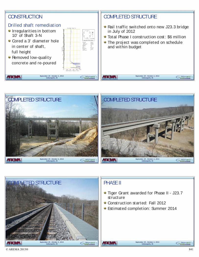
Near the completion of Phase I of the project, the P&L was awarded a Tiger III Grant to assist in funding Phase II, the replacement of Bridge J23.7. The P&L’s Phase I financial commitments to begin the replacement process for these aging structures, in combination with the success of Phase I, were considered key reasons why a grant was awarded. J23.7 construction began in the fall of 2012, with a scheduled completion in the summer of 2014. Figure 14 shows Phase II progress as of April of 2013.
© AREMA 2013®832
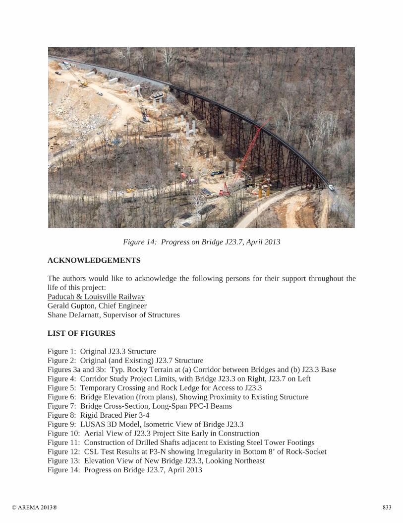
Figure 14: Progress on Bridge J23.7, April 2013
ACKNOWLEDGEMENTS
The authors would like to acknowledge the following persons for their support throughout the life of this project:Paducah & Louisville RailwayGerald Gupton, Chief EngineerShane DeJarnatt, Supervisor of Structures
LIST OF FIGURES
Figure 1: Original J23.3 StructureFigure 2: Original (and Existing) J23.7 StructureFigures 3a and 3b: Typ. Rocky Terrain at (a) Corridor between Bridges and (b) J23.3 Base Figure 4: Corridor Study Project Limits, with Bridge J23.3 on Right, J23.7 on LeftFigure 5: Temporary Crossing and Rock Ledge for Access to J23.3Figure 6: Bridge Elevation (from plans), Showing Proximity to Existing StructureFigure 7: Bridge Cross-Section, Long-Span PPC-I BeamsFigure 8: Rigid Braced Pier 3-4Figure 9: LUSAS 3D Model, Isometric View of Bridge J23.3Figure 10: Aerial View of J23.3 Project Site Early in ConstructionFigure 11: Construction of Drilled Shafts adjacent to Existing Steel Tower FootingsFigure 12: CSL Test Results at P3-N showing Irregularity in Bottom 8’ of Rock-SocketFigure 13: Elevation View of New Bridge J23.3, Looking NortheastFigure 14: Progress on Bridge J23.7, April 2013
© AREMA 2013® 833
Sept
embe
r 29
–O
ctob
er 2
, 20
13In
dian
apol
is,
IN
MIC
HA
EL O
’CO
NN
OR
, PE
PRO
JEC
T M
AN
AG
ERSC
OTT
WO
JTEC
ZKO
, PE
PRO
JEC
T EN
GIN
EER
© AREMA 2013®834

September 29 – October 2, 2013Indianapolis, IN
PRESENTATION OUTLINE
BackgroundExisting StructuresCorridor Study DesignConstructionCompleted Structure Phase II Progress
September 29 – October 2, 2013Indianapolis, IN
September 29 – October 2, 2013Indianapolis, IN
BACKGROUND
Located in West Point, Kentucky
September 29 – October 2, 2013Indianapolis, IN
– October 2, 2013Indianapolis, IN
BACKGROUNDOnly railroad servicing Fort KnoxStrategic Rail Corridor NetworkDefense Connector Line
September 29
Defense Connecto
September 29 – October 2, 2013Indianapolis, IN
– October 2, 2013Indianapolis, IN
BACKGROUND
J23.3 crosses historic L&N TurnpikeJ23.7 is 0.4 miles further west
September 29
J23.3
J23.7
September 29 – October 2, 2013Indianapolis, IN
EXISTING STRUCTURES
120+ years oldOpen deck Steel trestlesTower legs sit onconcrete/stonepedestals
September 29 – October 2, 2013Indianapolis, IN
EXISTING STRUCTURES
J23.3
© AREMA 2013® 835
September 29 – October 2, 2013Indianapolis, IN
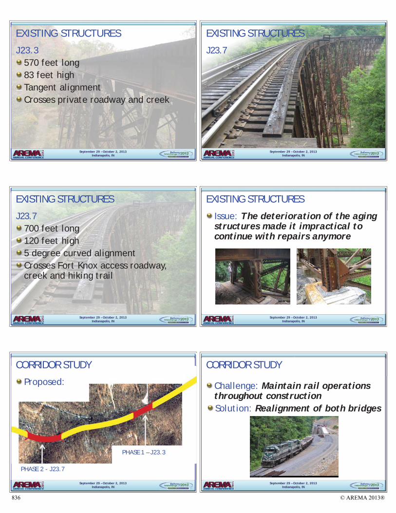
570 feet long83 feet highTangent alignmentCrosses private roadway and creek
EXISTING STRUCTURES
J23.3
September 29 – October 2, 2013Indianapolis, IN
EXISTING STRUCTURES
J23.7
September 29 – October 2, 2013Indianapolis, IN
EXISTING STRUCTURES
J23.7700 feet long120 feet high5 degree curved alignmentCrosses Fort Knox access roadway, creek and hiking trail
September 29 – October 2, 2013Indianapolis, IN
EXISTING STRUCTURES
Issue: The deterioration of the aging structures made it impractical to continue with repairs anymore
September 29 – October 2, 2013Indianapolis, IN
PHASE 1 – J23.3
PHASE 2 - J23.7
CORRIDOR STUDY
Proposed:
September 29 – October 2, 2013Indianapolis, IN
CORRIDOR STUDY
Challenge: Maintain rail operationsthroughout constructionSolution: Realignment of both bridges
© AREMA 2013®836
September 29 – October 2, 2013Indianapolis, IN
CORRIDOR STUDY
Challenge: Railroad built on steep, rocky slopes
Solution: Align railway to balance blasting, excavation and fill work
September 29 – October 2, 2013Indianapolis, IN
Challenge: Construction Access Rock and earth removed from uphill side placed on steep downhill sideModify cut section to include 40’ ledge to serve as temporary roadway
CUT
ction to include 40 ledgeemporary roadway
FILL
September 29 – October 2, 2013Indianapolis, IN
CUT
FILLCut Section
Fill Section - Spoil Area (Pier 2 Shown)
Section
FilFilFilFilFill
Temporary Crossing
September 29 – October 2, 2013Indianapolis, IN
CORRIDOR STUDY
J23.3
J23.7
EXISTINGALIGNMENT
PROPOSEDALIGNMENT
September 29 – October 2, 2013Indianapolis, IN
PROJECT TEAM
September 29 – October 2, 2013Indianapolis, IN
M
OWNER
LEAD ENGINEER
GEOTECHNICAL
GENERAL CONTRACTORENVIRONMENTAL
September 29 – October 2, 2013Indianapolis, IN
DESIGN - New J23.3 Bridge
ELEV
ATIO
NPL
AN
534 FEET LONG
© AREMA 2013® 837
September 29 – October 2, 2013Indianapolis, IN
DESIGN - New J23.3 Bridge EL
EVAT
ION
80 FEET TALL
PLAN
September 29 – October 2, 2013Indianapolis, IN
DESIGN - New J23.3 Bridge
ELEV
ATIO
N
Two Column Pier
Abutment
PLAN
September 29 – October 2, 2013Indianapolis, IN
DESIGN
Minimizing offsetLess than 30 ft. from existing alignment
September 29 – October 2, 2013Indianapolis, IN
DESIGN – Long span beams
CAST-IN-PLACECONCRETE DECK
2’–9” SPACING
72” PPC-I BEAM (SPECIAL)
92’ – 95’ SPAN LENGTHS
September 29 – October 2, 2013Indianapolis, IN
DESIGN – Long span beams
September 29 – October 2, 2013Indianapolis, IN
DESIGN
Longitudinal DeflectionTall, slender piers -> low stiffnessIrregular span layoutLongitudinal force > 5% of total superstructure dead load
Challenge: Keep deflection under 1”
Solution: Provide bearing continuity and rigid braced pier
© AREMA 2013®838
September 29 – October 2, 2013Indianapolis, IN
DESIGN – Bearing Continuity
BEARING TYPE – LOAD PATH
E E E E EF F F F F F F F F
September 29 – October 2, 2013Indianapolis, IN
DESIGN - Rigid braced pier
September 29 – October 2, 2013Indianapolis, IN
DESIGN - Rigid braced pier
September 29 – October 2, 2013Indianapolis, IN
DESIGN
3D Modeling
September 29 – October 2, 2013Indianapolis, IN
DESIGN - Seismic considerations
Behave elastically under Level 2 ground motion; Prevent collapse under Level 3 ground motionDetails:
Butt-welded hoops for confinement in plastic hinge zonesShear connector angles between bearingsStruts yield before columns
September 29 – October 2, 2013Indianapolis, IN
CONSTRUCTION - Sequence
Construction of: • Excavation support
system• Piers• Beam fabrication
© AREMA 2013® 839
September 29 – October 2, 2013Indianapolis, IN
CONSTRUCTION – Sequence
Construction of:• Abutments • Drilled shafts • Piers • Beam erection • Deck
September 29 – October 2, 2013Indianapolis, IN
CONSTRUCTION - Sequence
Construction of: • Abutment• Pier • Beam erection• Deck• Walkway
September 29 – October 2, 2013Indianapolis, IN
CONSTRUCTIONSite access
September 29 – October 2, 2013Indianapolis, IN
CONSTRUCTION
Rock blastingField monitoring to protect rail operationsBEFORE AFTER
September 29 – October 2, 2013Indianapolis, IN
CONSTRUCTION
Drilled shaft installationWithin 10’ of existing bridge foundationsExtend permanent casing ahead of auger
September 29 – October 2, 2013Indianapolis, IN
CONSTRUCTION
Drilled shaft testingCross Hole Sonic Logging (CSL) testingDetermine integrity of concrete
© AREMA 2013®840
September 29 – October 2, 2013Indianapolis, IN
CONSTRUCTION
Drilled shaft remediationIrregularities in bottom10’ of Shaft 3-NCored a 3’ diameter hole
in center of shaft, full height
Removed low-quality concrete and re-poured
September 29 – October 2, 2013Indianapolis, IN
COMPLETED STRUCTURE
Rail traffic switched onto new J23.3 bridge in July of 2012 Total Phase I construction cost: $6 millionThe project was completed on schedule and within budget
September 29 – October 2, 2013Indianapolis, IN
COMPLETED STRUCTURE
September 29 – October 2, 2013Indianapolis, IN
COMPLETED STRUCTURE
September 29 – October 2, 2013Indianapolis, IN
COMPLETED STRUCTURE
September 29 – October 2, 2013Indianapolis, IN
PHASE II
Tiger Grant awarded for Phase II - J23.7 structureConstruction started: Fall 2012Estimated completion: Summer 2014
© AREMA 2013® 841
September 29 – October 2, 2013Indianapolis, IN
PHASE II - J23.7 PROGRESS
September 29 – October 2, 2013Indianapolis, IN
PHASE II - J23.7 PROGRESS
September 29 – October 2, 2013Indianapolis, IN
PHASE II - J23.7 PROGRESS
September 29 – October 2, 2013Indianapolis, IN
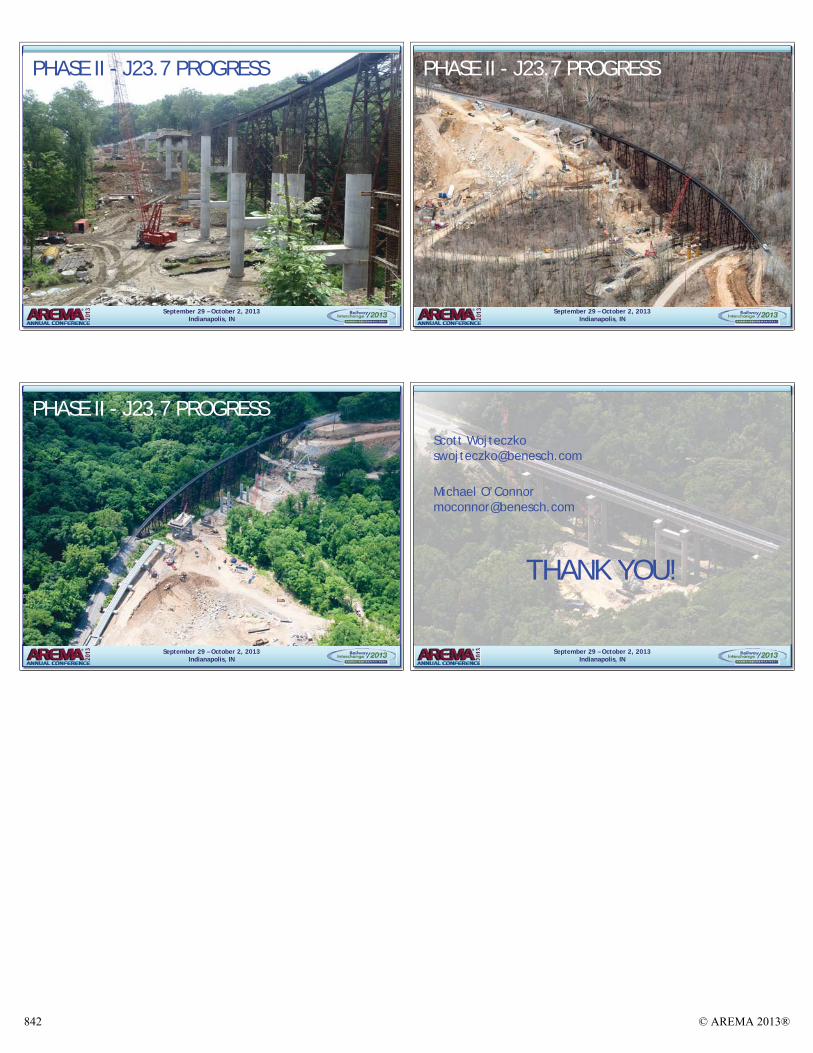
THANK YOU!
Scott [email protected]
Michael O’[email protected]
© AREMA 2013®842