design, construction and testing of an autonomous mine hunter
TRANSCRIPT

N PS ARCHIVE1997.12SCHMIDT, J.
NAVAL POSTGRADUATE SCHOOLMONTEREY, CALIFORNIA
THESIS
ThesisS337222
DESIGN, CONSTRUCTION AND TESTING OF ANAUTONOMOUS MINE HUNTER
by
Jeffrey A. Schmidt
December, 1997
Tjiesis Advisor:
Thesis Advisor:
Richard Harkins
Xiaoping Yun
Approved for public release; distribution is unlimited.

DUDLEY KNOX LIBRARYNAVAL POSTGRADUATE SCMONTEREY CA 93943-51U
DUDLEY KNOX LIBRARYNAVAL POSTGRADUATE SCHOOLMONTEREY, CA 939434101

REPORT DOCUMENTATION PAGE Form Approved OMB No. 0704-01
S
Public reporting burden for this collection of information is estimated to average 1 hour per response, including the time for reviewing instruction, searching existing data sources,
gathering and maintaining the data needed, and completing and reviewing the collection of information. Send comments regarding this burden estimate or any other aspect of this
collection of information, including suggestions for reducing this burden, to Washington Headquarters Services, Directorate for Information Operations and Reports, 1215 Jefferson
Davis Highway, Suite 1204, Arlington, VA 22202-4302, and to the Office ofManagement and Budget, Paperwork Reduction Project (0704-0188) Washington DC 20503.
AGENCY USE ONLY (Leave blank) REPORT DATEDecember 1997.
3 . REPORT TYPE AND DATES COVEREDMaster's Thesis
TITLE OF THESIS. Design, Construction and Testing of an Autonomous
Mine Hunter
6. AUTHOR(S) Schmidt, Jeffrey, A.
FUNDING NUMBERS
7. PERFORMING ORGANIZATION NAME(S) AND ADDRESS(ES)
Naval Postgraduate School
Monterey CA 93943-5000
PERFORMINGORGANIZATIONREPORT NUMBER
9, SPONSORING/MONITORING AGENCY NAME(S) AND ADDRESS(ES) 10. SPONSORING/MONITORINGAGENCY REPORT NUMBER
1 1 . SUPPLEMENTARY NOTES The views expressed in this thesis are those of the author and do not reflect the official
policy or position of the Department of Defense or the U.S. Government.
12a. DISTRIBUTION/AVAILABILITY STATEMENT
Approved for public release; distribution is unlimited.
12b. DISTRIBUTION CODE
1 3 . ABSTRACT (maximum 200 words)
Landmine detection is a immense technological problem. A small, low power metal detector would find application in
concert with other search technologies. A detection circuit was designed and constructed consisting of a search coil and a
CMOS exclusive OR gate forming an oscillator. This was interfaced to a microprocessor which counted the pulses from
the oscillator and decided whether a detection had been made. Detection range for an anti-personnel mine like object was
14 cm at the coil centerline. A robot platform to autonomously search for landmines was constructed..
14. SUBJECT TERMS Landmine, Induction, Robot, Microprocessor. 15. NUMBER OF
PAGES 56
16. PRICE CODE
17. SECURITY CLASSIFICA-
TION OF REPORT
Unclassified
SECURITY CLASSIFI-
CATION OF THIS PAGE
Unclassified
1 9 . SECURITY CLASSIFICA-
TION OF ABSTRACT
Unclassified
20. LIMITATION OFABSTRACTUL
NSN 7540-01-280-5500 Standard Form 298 (Rev. 2-89)
Prescribed by ANSI Std 239-18 298-102


Approved for public release; distribution is unlimited.
DESIGN, CONSTRUCTION AND TESTING
OF AN AUTONOMOUS MINE HUNTER
Jeffrey A. Schmidt
Lieutenant, United States Navy
B.S., University of South Carolina, 1988
Submitted in partial fulfillment
of the requirements for the degree of
MASTER OF SCIENCE IN APPLIED PHYSICS
from the
NAVAL POSTGRADUATE SCHOOLDecember 1997

r\ero AycKiv*
h°i9.a Jmt<^c\wK\cy\, 3\
d.p\

DUDLEY KNOX LIBRARYNAVAL POSTGRADUATE SCHOOLMONTEREY CA 93943-5101
ABSTRACT
Landmine detection is a immense technological problem. A small, low power
metal detector would find application in concert with other search technologies. A
detection circuit was designed and constructed consisting of a search coil and a CMOS
exclusive OR gate forming an oscillator. This was interfaced to a microprocessor which
counted the pulses from the oscillator and decided whether a detection had been made.
Detection range for an anti-personnel mine like object was 14 cm at the coil centerline. A
robot platform to autonomously search for landmines was constructed.

VI

TABLE OF CONTENTS
I. INTRODUCTION 1
II. THEORY 3
A. REVIEW OF SENSING TECHNOLOGIES 3
1. Electromagnetic 3
2. Miscellaneuos 6
B. COIL THEORY 7
1
.
Magnetic Field and Flux 7
2
.
Inductance 8
3. Mutual Induction 9
C. RLC OSCILLATOR THEORY 9
III. CONSTRUCTION AND OPERATION 13
A. SENSING CIRCUIT 13
B. SENSING COIL 15
C OSCILLATOR CIRCUIT CONSTRUCTION 16
D. OSCILLATOR CIRCUIT OPERATION 17
E. COUNTING CIRCUIT 24
F. MICROPROCESSOR 24
G. SAMPLING CIRCUIT OPERATION 25
H. ROBOT 26
1. 68HC11 27
2. 68HC11 / Tiny Giant Interface 28
3. Pulse Width Modulation 28
4. Motor Drive Chip 29
5. Motors and Shaft Encoders 30
6. Wheel / Speed Control 30
IV.TEST RESULTS AND CONCLUSIONS 31
A. TEST RESULTS 31
B. FUTURE WORK 33
C CONCLUSION 33
APPENDIX A. TINY GIANT C CODE 35
APPENDIXB. 68HC11 C CODE 37
LIST OF REFERENCES 43
INITIAL DISTRIBUTION LIST 45
vn

Vlll

ACKNOWLEDGEMENT
I would like to thank my advisors, Richard Harkins and Xiaoping Yun for the
freedom to tie myself in knots, and then the patience to untie me. George Jaksha brought
his mechanical genius to bear many times during this project, and was a reliable sounding
board for my ideas. Warren Rogers went above and beyond the call in explaining the finer
points of circuit analysis. Finally, thanks to my wife Jay and daughter Jessi, for without
whom none of this would mean much.
IX


L INTRODUCTION
A thesis is a long road with many turns. I have always been interested in
computers, and particularly at the level where digital meets analog. I have also been
interested in robotics. This thesis has been an opportunity to explore these areas in more
depth. A circuit for detecting conducting material in the ground, e.g. landmines, had been
developed by Goodnight (Goodnight, 1 996) and needed to be adapted for use on an
autonomous robot. These circumstances lead me to research the landmine issue.
Landmines and unexploded ordnance (UXO) present an almost insurmountable
problem. Detection is a tough technological challenge because the ground is a particularly
hard place in which to search. It's properties vary by geographic area, time of the day and
weather conditions. The object of the hunt is also getting harder to find. Mines are made
today with little or no metal. Ordnance removal is a slow, tedious task with severe
consequences for failure.
The problem is immense, and getting larger. The UN estimates there are over 1 1
million land mines laid, with millions more waiting to be used (UN, 1997). It costs only
$5 to deploy scatterable mines and $200 to $1,000 per mine and one life per 5000 to
remove them. For every mine removed twenty more are laid. At the current clearance
rates, and no new mines laid, it will take 4, 000 years to clear all the mines in Afghanistan.
(Walker, 1995)
They are indiscriminate and long lasting. Eight hundred deaths a month are
attributed to land mines. Last year 40 French farmers were killed from World War II
ordinance in their fields. Significant portions of Cambodia are denied civilian use because
of mines.
Practical detection of landmines is presently done primarily with manual search
techniques. A member of the local population probes the ground with a nonmetallic probe
centimeters at a time. When the probe hits a solid object, it is uncovered and identified.
The rate of clearance is on the order of square meters per day. It is a slow, tedious and

dangerous operation. It would be faster and safer to substitute a robot and automated
detection for the human.
Goodnight 's circuit was not suitable for robot use for several reasons. The circuit
depended on a manually turned inductor to balance the search coil. Adjustments could not
be made by the robot for varying environment conditions. The circuit was also extremely
sensitive to stray capacitance. Therefore I modified the Goodnight circuit to take these
into account.
This then, is the backdrop from which I began to develop a robot and attempt to
find landmines. This thesis will review landmine sensing technologies currently being
researched and briefly review possible robot types. Then a description of the circuit
eventually decided upon, with it's theory of operation, construction details and
experimental results.

H. THEORY
A. REVIEW OF SENSING TECHNOLOGIES
The solution to the landmine dilemma has three generally agreed on phases:
detection, classification, removal. There is much work in the sensing technology area,
which we will cover here. Some of the technologies are suited for ordnance clearance of
old battlefields and training areas, others are directed solely at landmine detection. Many
of these techniques require significant computer processing, are very large, and require
significant electrical power.
No one sensing technology dominates. Solving such a complex problem will
probably involve more than one sensing technique, and the fusion of data from many
sources.
1. Electromagnetic
a. Magneticfield
(1) Proton Precession Magnetometer. Fluid, usually water, is
placed in a container inside a solenoid. The solenoid axis is aligned orthogonally to the
field to be measured. The magnetic spin axis of the water's protons are aligned parallel to
the solenoid's axis when energized. When the solenoid is instantaneously de-energized,
the protons begin to precess about the axis of the magnetic field to be measured. This
procession induces an emf in the solenoid proportional to the magnetic field strength.
Resolution of 0.1 nT at 10 Hz is possible. (Bartington, 1994)
(2) Optically Pumped Magnetometer. This magnetometer uses
the Zeeman effect to measure the ambient field. Circularly polarized light from a cesium
metal vapor lamp is directed along the axis of the field to be measured. The light passes
through an absorption cell containing cesium metal vapor. The intensity of the beam from
the cell is proportional to the magnetic field strength. It has a sensitivity around the 10 pT
level. (Healey, 1995)

(3) Flux Gate. Because of it's small size, low power
requirements and good noise performance, the fluxgate magnetometer is the most versatile
magnetic sensor. It converts a static or slowly varying magnetic flux into an alternating
voltage which can easily be measured. A core of very high relative magnetic permeability
material is surrounded by a solenoid which drives it into saturation. The solenoid current
is alternated so as to saturate the core in different directions. When the driving current is
removed, a back EMF will be generated in the solenoid. If no external field is present, the
EMF will be symmetrical. However, if a field is present, the EMF will be asymmetric,
thus containing information about the field. (Jiles, 1991)
For low power, low bandwidth applications a single core
configuration would be used, where the driving current and back EMF would be applied
from the same coil. Such a configuration has been used for fusing sensors for both land
and sea mines. For greater accuracy, two primary coils surrounding cores wound in an
opposing sense. Two secondary coils are used, so that the driving signal does not appear
in the output. Use of an error feedback signal results in linearity errors as low as 0.001%.
(Bartington, 1994)
(4) Hall effect Magnetometer. Hall effect magnetometers use
the Hall effect to measure fields down to around a few uT in an area of about a mm2.
(5) Magnetoresistors. A relatively new technology involves the
variation in resistance in the presence of a magnetic field of certain materials. The
magnetoresistive effect is generated by the electron spin orbit coupling. The change in
electron distribution changes the scattering of the conduction electrons (Jiles, 1991).
Magnetoresistors used in a Wheatstone bridge circuit with two shielded magnetoresistors
will produce a voltage that varies as the ambient magnetic field changes. This circuit can
be made small and low power, however it detects ferrous materials only. (Healey, 1995)

b. Induction
Induction sensors measure the strength of a secondary magnetic field
induced by a primary coil. The resulting field is measured by a secondary coil. Although
they only detect conducting material, they are valued for their sensitivity.
c. Electromagnetic Radiation
(1) Ground Penetrating Radar. Ground penetrating radars
(GPR) commonly use frequencies of 30 Mhz to 2 Ghz. The strength of the reflected
signal depends on target distance, material, and orientation, and the soil characteristics.
The returned signal is examined for changes in amplitude, time delay, phase, polarization
and propagation direction. GPRs can be placed in four categories: short pulse, video
pulse, synthetic pulse, and frequency modulated continuous wave systems. Commercial
systems can detect wires and pipes at 13 feet underground. (TR-31 1, 1993)
(2) Passive Millimeter Detection. Passive millimeter wave
sensors (radiometers) detect mines by the difference in reflection of the low level radiation
from the sky. Metal and to a lesser extent, plastic, objects appear cold while the
surrounding soil is appears hot. Soil moisture has a large effect on sensor performance.
Success has been reported, (Yujiri 1 996), using a 1 2 Ghz sensor imaging metal and plastic
mines under leaves and sand to a depth of 4 cm. Groot (Groot, 1 996) found that surfaced
anti-personnel mines and buried anti-tank mines were not visible using a 94 Ghz
radiometer.
(3) X-ray Backscatter. Compton Backscatter Imaging (x-ray
backscattering) generates an image by detecting the reflected photons from an object.
Material with lower electron densities scatter more photons than more electron dense
materials do. Since plastics are less electron dense than soil or metal, they can be detected
this way, as can steel, which is more electron dense than soil. Since such high frequencies
are involved penetration depth is not great, but resolution is good. Generation ofx-rays
also requires a large power supply and space. (Keshavmurthy, 1996)

2. Miscellaneous
a. Tactile
Vibrations produced by moving a tactile sensor over a surface are different
for man made and natural materials. Plastic can be differentiated from metal, rock and
wood by the response to a probe inserted in the ground. Many probes can be inserted at
once to allow fairly rapid searching. (Arnot, 1996)
b. Odor Sensor
The sensitivity of dogs and certain insects' sense of smell leads hope that
the explosives in a mine can be detected. Artificial odor detectors exist but operate at
higher concentrations. (Machler, 1995)
c. Ion Mobility Spectrometry
An Ion Mobility Spectrometer detects the presence of a particular molecule
by ionizing it and then measuring the time to travel through a magnetic field in a tube.
The device is fast and can be compact, but it's sensitivity is not very high. (Machler, 1995)
d Reversal Electron Attachment
The NO2 compound in explosives has a high affinity for electrons.
Electrons at very low energies that hit the compound form characteristic anions or
disassociates in a unique pattern. A detector is being developed that can sense these
anions or disassociation patterns. (Chemical and Engineering News, 1997)
e. Nuclear Quadrupole Resonance
Some nuclei, such as nitrogen- 14 possess quadrupole moments. When
subjected to radio frequency radiation they respond with unique signals depending on the
nucleus and it's chemical environment. (Chemical and Engineering News, 1997)

f. Neutron analysis
A target illuminated with both fast and slow neutron beams will emit y-rays
of characteristic energies. Y-rays are analyzed from interactions from nuclei reacting with
fast and slow neutrons. Identification is based on the combined y-ray information.
(Chemical and Engineering News, 1 997)
B. COIL THEORY
1. Magnetic Field and Flux
All current carrying conductors produce a magnetic field. A conductor formed
into a coil will produce a magnetic field that can be calculated from the Biot-Savart law:
2(R 2 + x2
)A
where x is the distance on the axis from the coil, R is the coil radius, fi is the permeability
of free space and / is the current through the coil.
The flux of the magnetic field, <2>s„ is defined as
Ob =JB»ds.
A coil with constant current will produce a constant magnetic field and flux.
Faraday discovered that relative motion between a conductor and a magnetic field
will generate an electro-motive force (ernf) in the conductor. The emf generated is given
by:
dt
The minus sign indicates that the induced emf will oppose the change in flux.

Ifwe vary the current in the coil, the magnetic field will vary likewise, and
according to Faraday, 's law, an emf will be generated in the coil, opposing the change in
current.
2. Inductance
If the current is changed in coil, the emf induced by the changing flux will oppose
the current change. Inductance, L, is defined as:
L = -di//dt
For a flat packed coil ofN turns, the flux set up in each turn is the same for all turns. Thus
the emf generated would be:
d<$>Bs - -n—-—
.
dt
Equating the emfs generated gives:
d$>B di-n—— = -L—,
dt dt
and the inductance of the coil, can be written as the proportionality constant between the
current and the flux :
r&B = Li (1)
3. Mutual Induction
A changing magnetic field creates an electric field:
a

If conducting material is within the magnetic field of the coil with varying current,
the varying electric field will induce circulating currents, called eddy currents, in the
material:
J = aE
The eddy currents will circulate in a direction that will oppose the change that produced
them, according to Lenz's Law. These eddy currents will generate a magnetic field of
their own, and that will oppose the field that created them. This means that the lines of
flux through the original coil will be reduced. From equation (1), we see that if the flux is
decreased the inductance will be also. We will use this interaction to detect the presence
of conducting material.
C. RLC OSCILLATOR THEORY
The relationship between voltage, current and energy storage for a capacitor and
inductor is given in Table 1
.
Device Voltage Current Energy Storage
Capacitor v(t) = -ji(t)dtdv
C{v(t))-
Inductor v(/) = -Ldi{t)
dti(t) = j]v{t)dt = ^L(i(t))
:
Table 1 . Capacitor and inductor characteristics
The energy storage of a capacitor depends on the voltage across it, which can be a
function of time. Since a discontinuity in energy as a function of time would require an
infinite amount of power, energy, hence voltage, must be a continuous function of time for
a capacitor. Similarly, the current through an inductor must be a continuous function of
time.

The LC circuit shown in Figure 1 contains two energy storage devices, the
capacitor and the inductor. At time t = 0, a switch was closed, giving the circuit shown,
with the capacitor having an initial voltage V , and i = 0.
R
o—H(—O-
vc
+
Figure 1 . RLC Circuit
With the current direction as shown, and using the relationships in Table 1, the differential
equation for the circuit is:
di(t) 1 f
Differentiating once yields:
d%t) R di(t) 1
This is a homogeneous differential equation whose solution is of the form i(t) - Ke st
. The
characteristic equation for this RLC series circuit is obtained by substituting the assumed
solution into the differential equation and is:
^(r/M ]
/lc) = °-
The characteristic equation has two roots:
R
and.
2L
R_
2L
+\R l
J_4L2 ~ LC'
I *L _L4L2 LC
10

Depending on the values of R, L, C the roots may be real and equal, {R2/4L2
) = (l/LC),
real and unequal, [R2
J4L2
) > (l/LC), or imaginary and complex conjugates of each other,
(R2/4L2
) < (yLC) . The first two cases are the over damped and critically damped cases
and do not concern us.
The imaginary roots can be written as sl2 = a ±jj3 , where = {R/2LJ , and
P = tJ{\/LC) - [R2/4L2
) . The assumed solution has to be modified for this case to :
i(t) = Kxe-
{a -lP)t +K2e-
{a+,P)t. (2)
Using the initial condition of no current, gives Kl+K
2=0. The other initial condition,
di/dt = -[V /Lj, is determined by the capacitor initial voltage ofV
gwesK^-K2=:-(vj2jLp).
Substituting the constant values in equation 2 and applying Euler's identity gives
the current as a function of time:
i{t) = -{vjLp)e-«smtp. (3)
Using the relationship from Table 1 for the voltage of a capacitor yields:
vc (t) = (v /j3ylLC)e-atco!{tp -arctan(a //?)]. (4)
The results, equations 3 and 4, show that the voltage across the capacitor (which is
the voltage across the resistor and inductor) is almost 180 degrees out of phase with the
circuit current. The oscillations result from the continuous exchange of energy between
the capacitor and inductor.
Figure 2 shows the curves for the circuit in Figure 1 with values R = 2 ohms, L =
1 mH, C = |j.F, and initial capacitor voltage of 1 V.
11

12
10
8-
I 1 1 1 1 1 1
1 1 1 1 1 1 1
1 1 1 1 1 1 1
\ T~~.—
i
i 1~1 r
~1
\ i i i i i i i
\ i i i i i ii.1r
, , ! ! T !
\ 1 1 1 1 1 II\ Voltage i i i i i i
\ i i i i i i i
\ i i i i i i i— \ - t 1 i 1 1 -t 1
\ i i i i i i i
\ '~ »i ^\ i i i i i
\ _ -fCtirrenti-Z -\j , 1 + 1
\ ' f bC \ i i i i
\ ' / /\ '\ '^—^~^ ' '
i
i
i
i
i
i-2 -
0.005 0.01 0.015 0.02 0.025
Time - Seconds
0.03 0.035 0.04
Figure 2. RLC Circuit Response
12

in. CONSTRUCTION AND OPERATION
A. SENSING CIRCUIT
The circuit developed was based on Anglin, 1 977, shown in Figure 3
.
3-18V
VOLUME
36 pf
X403C
tO niH
SEARCH COIL
(AWG 18, UC TURNS. 6 IN. DIAMETER)
TWIN-OSCILLATOR METAL DETECTOR—Metatobject near search coll changes frequency of
oscillator A, which is initially tuned to 160 kHz,
thereby changing frequency of 1-kHi output de-
rived by mixing with 161 -kHz output of Aj. Sen-
sitivity, determined largely by cBmensions of
search coil, is sufficient to detect coins about 1
foot away.—M. E. AngRn, CMOS Twin Oscil-
lator Forms Micropower Metal Detector, elec-
tronics. Dee. 22, 1877, p 78.
Figure 3 . Twin Oscillator Metal Detector
The circuit output of Figure 3 is a tone that varies when conducting material is
encountered. The signal from the detecting circuit is mixed with a generated signal that
produces a 1 KHz tone. This frequency changes and is detected by an operator on
headphones. Since the circuit is to be interfaced to a microprocessor, it's output must be
converted to a digital form. The best approach was to count the frequency coming from
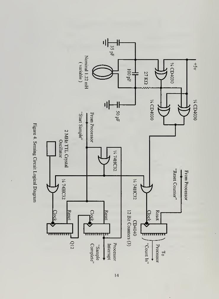
the sensor circuit directly. The circuit developed is shown in Figure 4. The various parts
of the circuit's operation and construction will be explained in the following paragraphs.
13
eg
o>
4^
C/3CDS3
— •
iOQ
n
|«-*
roOQ.o'P3
P3OQ
1
sir ±^CD
CD
5 3oGO
O
V
d •-0
o oc o13 ft)p* on
C/1
r o
Ho
14

B. SENSING COIL
Various coils were constructed from thirty gauge wire wound on circular forms.
They were of different diameters and number of windings, listed in Table 2, and shown in
Figure 5.
Diameter
(cm)
Turns Measured
Inductance
(mH)
Operating
Frequency
(KHz)
10 26 .159 1000
15 49 .855 387
20 13 .093 1200
20 25 .342 614
20 34 .633 425
20 49 1.22 280
30.5 70 3.51 169
Table 2. Sensing Coil Measurements
Figure 5. Search Coil
15

C. OSCILLATOR CIRCUIT CONSTRUCTION
The circuit was initially constructed entirely on a breadboard, with a coaxial cable
connecting the coil and the oscillator. While the circuit operated properly, the oscillation
frequency was not constant. As will be discussed later, the frequency pulses are counted
for a constant period of time. The number of counts varied from sample to sample by up
to ten with no conductor present. This noise reduced the sensitivity of the detector to an
unacceptable degree. The circuit was also very sensitive to movement, temperature and
human presence.
Since the LC circuit uses such a small capacitance ( 1 00 pF), it was extremely
sensitive to stray capacitance caused by the movement of the coil leads, the movement of
wires on the breadboard, and human limbs that happened to be nearby. The oscillator
circuit was moved to a small circuit board next to the coil, as can be seen in Figure 6.
::^;|- ::mkUi\mmmM^-I -1*j |§§j
:
Figure 6. Oscillator Circuit Board
The circuit board was constructed with the components as close together as
practicable and on a ground plane. The ground plane removes any stray capacitance
influence on the oscillator.
Placing the oscillator as close as possible to the coil had three beneficial effects.
The coaxial cable connecting the coil and oscillator, at 200pF per foot intrinsic
capacitance, had twice the capacitance as the LC circuit capacitor. Eliminating this
capacitance let the circuit oscillate at a much higher frequency with a given coil. The
cable capacitance also had a temperature dependence, as seen when warmed just a few
16

degrees. The circuit operation was more stable since the length of the un-amplified
oscillator signal was reduced to the absolute minimum. A coaxial cable was used to
connect the amplified oscillator output and the counter circuit, with the outer conductor
tied to the ground plane, to prevent the position of the output wire affecting oscillator
frequency by stray capacitance.
Capacitors used in the initial construction were of an unknown specification.
Operation outside was more variable than inside due to the temperature characteristics of
the capacitors. Capacitors of the COG specification were used and operation improved.
Standard CMOS construction techniques were used in constructing the circuit. A
small bypass capacitor was placed across the power supply pins of the CD4030 to reduce
the power supply line fluctuations caused when the chip suddenly turns on. The unused
inputs were grounded to prevent oscillation.
D. OSCILLATOR CIRCUIT OPERATION
Figure 7 shows the oscillator portion of the sensing circuit. The key to the
operation of the circuit is the LC tank formed by the capacitor C3 and inductor L, the
search coil. The tank's frequency will change in the presence of conducting material as
described before.
^^v.+5
vc,
Figure 7. Oscillator Circuit Diagram
17

The logic gate in Figure 7 is a CD4030 CMOS exclusive OR gate (XOR). Since
on input is tied to logic one (+5 Vdc), the output of the gate will be opposite of the other
input. A voltage level of 3. 1 55 Vdc or higher on the input is a logic level one, and a logic
level zero is 2.45 Vdc or below. When the gate is on, it supplies 5 Vdc through the upper
FET in it's output stage. See Figure 8.
X
Hi1 zr
?Ja
2
Vcc
WfhH1
Figure 8. CD4030 Gate Schematic
When the output is logic level zero, it connects the output to ground through the lower
FET, and is essentially at ground potential.
The sensing circuit was simulated on MicroSim_8, a circuit simulation program
based on PCSPICE. Since the simulation library for the CD4030 chip was not available,
circuit simulation was divided into 2 phases. When the XOR gate outputs a logic one, it
was replaced with a 5 volt source. When the gate outputs a logic level zero, it was
replaced by a ground.
The simulation started with all voltages and currents zero. Since the gate output a
logic level one, it was replaced with a 5 volt source. The voltage at the upper terminal of
C2 (VC2 in Figure 7) was monitored and the simulation continued until it reached the
logic one level, 3.155 Vdc. The voltages of the capacitors and current through the
inductor was recorded and entered as initial conditions for the other phase of the
simulation.
Since at 3.155 Vdc the XOR gate output will go low, it was replaced with a
ground. The initial conditions were entered. The VC2 was monitored until it reached
18

2.45 Vdc, the logic zero level. The voltages and currents were recorded and used as
initial conditions for the other phase.
Circuit voltages were measured with a digital storage oscilloscope at the output
and the upper terminals of CI (VC1) and C2 (VC2). From VC1 and VC2 the voltage
across the coil and resistor R of Figure 7 was calculated. The measured waves are plotted
in Figures 9, 10, 11 and 12. The results of the SPICE simulation are plotted in Figures 13
and 14. Figure 13 shows the voltages across CI, C2, the coil and the output. Figure 14
plots the currents through the inductor L (the search coil), capacitors CI, C2 and C3, and
through R. All currents are positive from the top of a component downward.
As can be seen, the shapes of the simulated waves matches well with those
measured. The period of oscillation was faster than actual, and the voltage across the coil
larger than measured. However, the wave forms did match well with the measured waves.
The value of this simulation was the current waves, which are not easily measured.
When the XOR gate is at logic one, current is coming from the gate through
resistor R. The power delivered by the gate makes up for the losses suffered in the
oscillator by the circuit resistance. As the gate comes on the voltage across the coil is
nearly zero, and current is through the coil and C3 is nearly at it's maximum. Current and
voltage are almost 180 degrees out of phase, as seen in the discussion of the RLC circuit
previously. The current is going through the coil from bottom to top and the current
through C3 is going in the opposite direction. Current is circulating around the tank
circuit. Some of the gate current is also charging capacitor CI, while C2 is discharging.
As the currents die away, the voltage across the coil becomes a maximum and the currents
a minimum. Current in the tank circuit begins circulating in the opposite direction, and C2
begins charging up.
When the voltage on C2 reaches 3.155 Vdc, the gate turns off. This makes no
immediate difference to the current circulating in the tank circuit. However, current is
now flowing back through resistor R to ground, through the turned offXOR gate. As can
be seen from the measured voltages in Figure 9, the output square wave is not a 50% duty
cycle, it is on more than it is off.
19

vc2
6
5
4
' 2
1
I I I I I I I I
ri
1 i
1
I
*W ;
1
0.5 1 1.5 2 2.5
time - seconds
3.5 4.5
x 10
Figure 9. C2 Voltage Vs Output Voltage
vc1
5 ---
CD
D)CO
-1
I I I I I I I
Mi
i j L.
J
1
1
"
-X_ ' « 1 ^--i**w
0.5 1 1.5 2 2.5 3 3.5
time - seconds
Figure 10. CI Volateg Vs Ouput Voltage
4 4.5
x10'6
20

6
vcoil
i i i i I I I I
b
4
3
a> 2
1 1
o
-ri
Y*W-TT --,--i
-, \
1
-2
-3
0.5 1 1.5 2 2.5
time - seconds
3.5 4.5
x 10"
Figure 1 1 . Voltage Across the Coil Vs Output Voltage
vr
5—
-
Q) 2
1 1
-1
-2
I I I I
1 1 I 1
I I 1 I
1 1 1 i
i
i
!f—
-
i
i i i i
i i i i
i
i
i i i
i i i i
i
i
i
Y»W
i i i i
i i i i
i i i i
i i i i
1_ --j r- -i~-
i i i i
i i i i
i i i i
Ji
j
i
1
i
i
i
™*fi i i i
i i i i
i i iJr\ \
i
j
0.5 1.5 2 2.5 3
time - seconds
3.5
x 10
4.5
6
Figure 12. Resistor Voltage Vs Ouput Voltage
21

I
Ln
Figure 13. SPICE Simulation Circuit Voltages
22

n 01
n
o
H o |
I-1
en -!
cw 1
<
H
nto M
|
t»
o -J
£ !
H-
to
O -t
U1
oC
C
Figure 14. SPICE Simulation Circuit Currents
23

E. COUNTING CIRCUIT
The output of the coil circuit is monitored by counting the pulses of the square
wave it produces. The coil output is counted by a CMOS CD4040 12 bit counter.
CMOS was used because of it's low power requirements and good noise immunity. Since
only the lower 8 bits vary from sample to sample, one counter is sufficient even though it
does roll over.
The pulse generator provides the time base for counting pulses from the coil.
More important than the exact time of the pulse is consistency from pulse to pulse.
Crystal oscillators are very stable and so was used here, and in the TTL package required
no further circuitry. CMOS CD4040 12 bit counters were used to divide down the crystal
frequency. To get the desired pulse length two counters were cascaded. The most
significant bit of the lower counter was the clock for the upper counter. This also
facilitated changing the pulse length by simply moving the "Sample Complete" line (Figure
4) to a different counter output. The counting circuit was constructed on a breadboard,
which was suitable for initial construction and allowed rapid changes.
F. MICROPROCESSOR
The controller used to direct operations is a Tiny Giant from Z-World Engineering.
It uses a Z180 microprocessor running at a clock speed of 9.216 MHz. It has 256K bytes
of battery back static RAM and 256K EEPROM. It has two serial ports and 16 general
purpose digital I/O lines arranged in two 8 bit ports, PA and PB. The I/O lines can be bit
configured for input or output, and the input lines can generated processor interrupts.
The 12 bits of the coil counter are connected to I/O lines PBO to PB6 and PAO to
PA4. Input bit PB7 generates the processor interrupt, "Count Complete". Lines PA5
through PA7 are outputs, PA7 "Reset", PA6 "Start count", and PA5 indicates mine found.
The Tiny Giant is programmed with Z-World's Dynamic C compiler, a near ANSI
C compliant compiler. Maximum program size is 4,000 lines.
24

G. SAMPLING CIRCUIT OPERATION
The processor prepares for a sample cycle by asserting the "Start Sample" line
high. Bringing "Start Sample" high forces the first OR gate output high, which in turn
forces the second level OR gates to go high, blocking the pulse trains of the coil and 2
MHz crystal from their respective counters. The "Start Sample" line high also resets the
pulse counters. The "Reset Counter" line is then brought high, then low, clearing the coil
counters.
The sample is initiated by de-asserting the "Start Sample" line. This forces the
output of the first OR gate low, since the pulse counters have been cleared, and their
output is low also. The outputs of the second level OR gates now depend on the coil and
crystal outputs. Since the these OR gate outputs are the counter clock inputs, the
counters begin counting.
The pulse counters count until the output that has the "Sample Complete" line on
it goes high. When this happens, the first level OR gate's output is forced high. This in
turn forces the second level OR gates high, blocking the coil and crystal pulse trains,
stopping the counters. The "Sample Complete" line going high also interrupts the Tiny
Giant. The processor then reads the number of pulses from the coil counter. Refer to
lines 102 through 108, in Appendix A for details.
To allow for the variation of coil counts due to noise while no conductors are
present, the microprocessor computes a 16 count moving average while the next count is
being taken. A detection is signaled if the latest count is greater than 5 above the running
average. Refer to lines 82 through 87, in Appendix A for details.
The sensor coil used oscillates in the circuit at 425 KHz. To obtain an adequate
number of counts to get reliable detections, a pulse length time of 0. 13 seconds was best.
It was a trade off between number of counts difference in a pulse and the speed of advance
that this would allow the robot.
25

EL ROBOT
A three wheel configuration using differential drive front wheels with a single
passive rear wheel was built. To get sufficient ground clearance, 25 cm diameter tires
were fitted. The treads were made of packing foam with a 10 cm tread to minimize
footprint pressure. The wheels are driven by two 24 volt DC motors using two 3 amp-
hour 12 volt DC batteries. The motors are powered by a SGS-Thomson dual full bridge
driver chip controlled by a Technological Arts ADAPT 1 1 68HC1 1 microprocessor. See
Figure 15.
11^
Figure 1 5 . The Robot
26
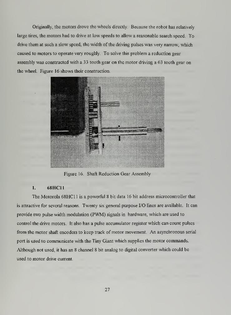
Originally, the motors drove the wheels directly. Because the robot has relatively
large tires, the motors had to drive at low speeds to allow a reasonable search speed. To
drive them at such a slow speed, the width of the driving pulses was very narrow, which
caused to motors to operate very roughly. To solve this problem a reduction gear
assembly was constructed with a 33 tooth gear on the motor driving a 63 tooth gear on
the wheel. Figure 16 shows their construction.
:iMSWMMWWWZM>M^:
Figure 16. Shaft Reduction Gear Assembly
1. 68HC11
The Motorola 68HC1 1 is a powerful 8 bit data 16 bit address microcontroller that
is attractive for several reasons. Twenty six general purpose I/O lines are available. It can
provide two pulse width modulation (PWM) signals in hardware, which are used to
control the drive motors. It also has a pulse accumulator register which can count pulses
from the motor shaft encoders to keep track of motor movement. An asynchronous serial
port is used to communicate with the Tiny Giant which supplies the motor commands.
Although not used, it has an 8 channel 8 bit analog to digital converter which could be
used to motor drive current.
27

The ADAPT 1 1 board comes with the 68HC1 1 and a Xicor X68C75
Microperipheral chip. The X68C75 has 8K EEPROM and two 8 bit I/O port replacement.
All bus signals for the 68HC1 1 and X68C75 are brought out to a 50 pin header.
The 68HC1 1 is programmed with a near ANSI C compiler from ImageCraft. It
supports floating point data types, has a multitasking library, and allows imbedded
assembly language programming. Interrupt routines can be written in the C language.
2. 68HC1 1 / Tiny Giant interface
The Tiny Giant sends motor control commands to the 68HC 1 1 over a
asynchronous serial link. The Tiny Giant uses a supplied library function to send the
commands, which are the bit masks the 68HC1 1 will use to control the motor.
Commands consist of three ASCII characters, the first indicating the directions of the two
motors and the last two indicating the speed of each wheel.
The 68HC1 1 uses an interrupt routine to handle the incoming characters. When
the serial port has received a character an interrupt is raised, and program control is
vectored to the routine. Since three characters will be sent, the interrupt routine first
disables further interrupts and waits for the next two characters. All three characters are
placed in global variables, and a flag is set to let the main program know that a new motor
command has been received. The applicable code is on lines 159 through 175 in Appendix
B.
3. Pulse Width Modulation
The PWM signals are generated by the 68HC1 1 hardware after initialization and
the loading of the appropriate register with the desired pulse length. The pulses are
generated by an internal 68HC1 1 free running 16 bit clock and three compare registers.
The timer counts up to 65,536 (216
) and then rolls over to zero and counts up again. A
68HC1 1 register, the Output Compare register 1 (OC1), is configured to force two output
pins, (PA5 and PA6), high when the free running timer is zero. Output Compare registers
OC2 and OC3 are configured to bring PA5 and PA6 low when the counter equals the
values in their Timer Output Compare registers TOC2 and TOC3.
28

The free running timer is driven at one-fourth of the system clock, which 8 MHz.
This yields a clock pulse of 0.5 |o.sec. The timer will roll over in 65,536 counts of 0.5 usee
or 32.77 msec, which will be the period for the PWM. The motor orders received from
the Tiny Giant are placed in the TOC2 and TOC3 registers and thus control the motor
speed.
4. Motor Drive Chip
The SGS-Thomson L298 Dual Full Bridge Driver is a one chip motor drive
solution. It allows motor operation in forward and reverse directions from a single
polarity power source. Motor direction is controlled by two inputs, Input 1 and Input2 of
Figure 17. When one input is logic level high and the other low, opposite FETs conduct
(1 and 4 or 2 and 3 of figure 17) and the motor spins in one direction. When the input
signals are reversed, the opposite FETs conduct and the motor spins in the opposite
direction. The Enable input must be high for any of the FETs to conduct, and the PWM
signal is applied to here. Motor drive voltage can be as high as 42 volts, and two amps
per bridge can be supplied. The logic voltage supply is 5 volts.
Leads to motors Motor power supply
Input 1
Input 2
Enable
Ground
Figure 17. L298 Motor Control Schematic
29

5. Motors and Shaft Encoders
The motors have an integral reduction gear and shaft encoder. The reduction ratio
is 19.7 to 1 . The shaft encoder generates two channels of 100 pulses per motor revolution
which are offset by 90 degrees allowing a determination of the direction of rotation of the
motor shaft. The motor reduction ratio of 19.7: 1 and the outer gear box reduction of
1.91 : 1 gives 3760 pulses per revolution of the robot tires. The tire diameter of 25
centimeters yields approximately 47 pulses per centimeter of robot travel.
6. Wheel / Speed Control
Terrain unevenness and small differences in tire diameter will caused the robot to
follow a curved path when a straight one has been ordered. To compensate for this, the
pulses from the encoders are periodically compared, and the pulse width of the motor
drive changed appropriately.
The 68HC1 1 has a register associated with one input line, the Pulse Accumulator,
that will count the pulses on the input line. One shaft encoder is tied to this input. The
other shaft encoder is tied to the clock input of a CD4020 1 2 bit binary counter. The
seventh bit of the counter is connected to an interrupt input of the 68HC1 1 . When the
counter sets the seventh bit, the processor is interrupted. The interrupt routine, lines 88
through 107 of Appendix B, reads the Pulse Accumulator and resets it to zero. It then
compares that value to the known number of pulses that causes the interrupt. A
proportional amount is either added or subtracted from one of the TOC registers to
balance the uneven pulses.
This correction is not needed if the robot has been commanded to turn, and the
main program will clear the binary counter if it receives a motor command that is not
forward or reverse at equal speeds.
30

IV. TEST RESULTS AND CONCLUSIONS
A. TEST RESULTS
1. Detection Ranges in Air
The detection ranges for different coils was tested in air, with a mine simulant.
The simulant is a metal can 5.4 cm in diameter and 7.6 cm tall, which is smaller than the
American M-14 antipersonnel mine. The simulant was placed on the coil centerline at
various depths, measured to the top of the simulant. Detections were signaled when the
counts of a sample period, 0. 13 sec, were 5 above a running average of the last 16
sample periods. The range that produced consistent detections was recorded. Table 3
contains the results. The best performing coil, 20/25 could detect an American World
War II anti -tank mine, 19 cm diameter 7.6 cm tall, at 28 cm below it's centerline. The
30/70 and 20/13 coils were unstable, periodically signaling false detections.
Coil
Diameter (cm)
/ Turns
Detection
Range (cm)
10/26 8.9
15/49 10.5
20/13 14.3
20/25 14.0
20/34 12.4
20/49 11.1
30/70 8.8
Table 3 . Detection Ranges
The sensitivity of the 20 cm diameter coils increases with decreasing turns. As the
number of turns decreases the frequency of coil oscillation goes up. Since the detection
circuit counts the pulses from the circuit, more pulses in a sampling period will give a
bigger change in counts in the presence of conducting material. The difference in counts
31

was recorded when the mine simulant was placed 10.5 cm below the coil on it's centerline
for the 20/ 25, 20/34, 20/49 coils, and tabulated in Table 4. As shown the difference in
counts varied linearly with oscillation frequency.
Coil
Diameter (cm)
/ Turns
Operating
Frequency
(KHz)
Freq
Change
(%)
Count
Difference
Count
Change
(%)
20/49 280 - 8 -
20/34 425 150 12 150
20/25 614 220 16 200
Table 4. Coil Sensitivity
The 20/25 coil was tested for radial sensitivity. The distance from the coil
centerline to the center of the simulant at various depths was recorded. Again, the
recorded range produced consistent detections. No angular dependence in detection was
noted. Figure 18 displays the results. The mine simulant, whose top was just on the
surface, could be detected up to 5. 1 cm beyond the radius of the coil. This is most likely
due to end effects of the coil magnetic field detecting the bottom of the target.
Q.
Q
u i1
' ' r 1
'1 4"
4-2.
-f
-4 + "
+-6
++
-8+
++
10
+
++
12
H
++
+
i
-140 4 6 8 10 12 14 16
Distance from coil centerline - cm18
Figure 18. Detection Distance Vs Target Distance From Coil Centerline
32

2. Robot Performance
Due to an equipment casualty, the robot was not field tested, nor was the
integration of the sensor tested.
B. FUTURE WORKThe main area for continued work could be completing the integration of the
detector with the robot. Further research could focus on the controlling microprocessor,
robot size and capabilities. The efficiency of various search behaviors could be explored.
Actions after detection have not be explored.
The Tiny Giant is a large microcontroller board, with many capabilities not needed
in the operation of the detection circuit. There are many smaller alternatives, particularly
the PicStic© from Circuit Cellar Inc. It has most of the capabilities needed in an area of
less than 2.5 cm2, requiring much less power.
Much work is being done in smaller wheeled and walking robots. The tradeoffs
between computer power, robot capabilities, and power requirements needs to be
explored. The usefulness of the swarming behavior of a large number of relatively dumb
may be effective in finding mines.
C. CONCLUSION
The adaptation of the sensing circuit has been successful. A 20 cm coil can detect
metallic anti-personnel at 14 cm on it's axis and an anti-tank mine at 28 cm. Further
investigation into the controlling microprocessor should yield a detector that is small and
uses very little power. It should compliment other sensing technologies very well.
33

34

APPENDIX A1
2
3
4
5
6
7
8
9
10
11
12
13
14
15
16
17
18
19
2021
22
23
24
25
26
27
282930
31
32
33
3435
36
3738
39
4041
4243
4445
4647
484950
51
52
53
5455
5657
// search .
c
// revised 14 Sep 97 - 24 Aug 97
// Show all counts with running ave.
#INT VEC PIOB VEC INT1
int datah, datal;int data_avail;
main (
)
{
int i ;
int index;unsigned int ave;unsigned int total;int counts [16];int ans
;
int num;
// PA6,7,5 output, all others input// PA6 Start count, active low// PA7 Reset, active high// PA5 interrupt ledoutport( PIOCA, Oxff );
outport( PIOCA, Oxlf );
// All input, PB7 interruptoutport( PIOCB, Oxff );
outport( PIOCB, Oxff );
outport( PIOCB, PIOB_VEC );
outport( PIOCB, 0xf7 );
outport( PIOCB, 0x7f );
data_avail = 0;
index = 0;
total = 0;
num = 0;
while ( index < 16 ) {
if ( data_avail ) {
outport ( PIODA, OxcO);outport( PIODA, 0x40);outport ( PIODA, 0x00);data_avail = 0;
total += datah;counts [ index ] = datah;index++;
} // end if} // end while
// reset, stop count// un-reset, stop count// start count
35

58
59
6061
62
63
64
65
66
67
68
69
70
71
72
73
74
75
76
77
78
79
80
81
82
83
84
85
86
87
88
89
90
91
92
93
94
95
96
97
98
99
100
101
102
103
104
105
106
107
108
109
110
111
112
index = ;
ave = total >> 4;
while
if data avail {
ave + 5
// reset, stop count// un-reset, stop count// start count
if ( datah >
num++;printf( "Got it! %x\n", datahoutport ( PIODA, OxcO)outport( PIODA, 0x40)outport ( PIODA, 0x00)data_avail = 0;
)
else {
printf ( "data %x, ave %x\n", datah, ave );
outport ( PIODA, OxcO); // reset, stop countoutport ( PIODA, 0x4 0); // un-reset, stop countoutport ( PIODA, 0x00); // start countdata_avail = 0;
total -= counts [ index ]
;
total += datah;counts [ index ] = datah;index++;index &= OxOf;ave = total >> 4;
} // end if ( datah > ( ave + 5 ) )
} // end if ( data_avail )
// end while
// end main
interrupt reti INT1(){
EI ( ) ;
datal = inport ( PIODB )
;
datah = inport ( PIODA )
;
datah &= Oxlf;datah <<= 7;
datal &= 0x7 f;
datah |= datal;data_avail = 1;
return;
} // end int
36

APPENDIX B1
2
3 /*
4 * base .
c
5
6 * Controls the motor operations. Receives commands from the7 * Tiny Giant via the serial port.8
9 * 3 Sep 9710 *
11 * Pin connections -
12 *
13 * Outputs : pins14 *
15 * 68HC11 ADAPT11 Colors of plug wires16 *
17 * PA5 8 PWM of 1 motor, 6811 OC3, L298 (EnableB, pin 11]
18 * White19 * PA6 7 PWM of r motor, 6811 OC2, L298 (EnableA, pin 6)
20 * Yellow21 * XPB7 42 nc22 * XPB6 41 12 volt relay23 * Yellow24 * XPB5 40 shaft counter reset25 * XPB4 39 24 volt relay26 * Orange27 * XPB3 38 right motor direction (L298 Input2, pin 7)
28 * Green29 * XPB2 37 right motor direction (L298 Inputl, pin 5)
30 * Blue of blue/green31 * XPB1 36 left motor direction (L298 Input4, pin 121
32 * Red33 * XPBO 35 left motor direction (L298 Input3, pin 10;
34 * Blue of blue/red35
36 * XPA7 14 Debugging info LEDs37
38 *
39
40 *
41
4243
4445 * Inputs
:
46 *
47 * PD0 48 Serial in from Tiny Giant48 * PA7 6 Shaft encoder input, Pulse Accumulator49 * PA0 13 Shaft counter interrupt, IC350 * PA1 12 STOP ! interrupt51
52 */53
54
55 #include <stdio.h>56 #include <hcll.h>57 #include <xicor.h>
37
XPBl 36
XPBO 35
XPA7 14XPA6 15XPA5 16XPA4 17
XPA3 18
XPA2 19
XPA1 20XPA0 21

58 #include "hcll_def.h"59
60 #define SHAFT_INC 12861 #define SHAFT_TOL 5
62 #define CORR_FACTOR 3
63
64 /* Global data *,
65
66 char robot_dir;67 char l_mtr_spd;68 char r_mtr_spd;69 char sci_status; '
70 char no_order;71 int s_travel;72 int diff;73 int lspeed, rspeed;74
75 /*
7g *****************************************************************
77 shafts ()
78
79 Check pulses from both shafts. If not equal, adjust both80 to maintain equal travel.gj *****************************************************************
82 */
83
84 #pragma interrupt_handler shafts85 void shafts () {
86
87 sjravel = PACNT;88 PACNT = 0;
89
90 diff = s_travel - SHAFT_INC;91 if ( diff > SHAFTJTOL ) {
92 lspeed = TOC2
;
93 rspeed = TOC3;94 lspeed += diff « CORR_FACTOR;95 rspeed -= diff « CORR_FACTOR;96 TOC2 = lspeed;97 TOC3 = rspeed;98 }
99 else if ( diff > -SHAFTJTOL ) {
100 diff = - diffj101 lspeed = TOC2,102 rspeed = TOC3,103 lspeed -= diff « CORR_FACTOR;104 rspeed += diff « CORR_FACTOR;105 TOC2 = lspeed;106 TOC3 = rspeed;107 }
108
109 } /* end shafts () */
110
111
112
113 /*
jj4 *****************************************************************
115 stop()
38

116
117
118
119
120
121
122
123
124
125
126
127
128
129
130
131
132
133
134
135
136
137
138
139
140
141
142
143
144
145
146
147
148
149
150
151
152
153
154
155
156
157
158
159
160
161
162
163
164
165
166
167
168
169
170
171
172
173
Handle the suicide button, connected to IC2, PA1, pin 12.
Will denergize the 24 volt relay after stopping PWM,wait a little, then denergize the 12 volt relay, puttingitself to sleep forever.Don't bother to clear the interrupt flag, since don'texpect to return!
******************************************************************/
#pragma interrupt_handler stopvoid stop ( ) {
int j ;
OC1M = 0x00;for ( j = 0; j < 40000; j++XPORTB &= V24_OFF;for ( j = 0; j < 40000; j++XPORTB &= V12 OFF;
/* Stop PWM/* Wait for things/* to setle down
/* Bye . . .
*/*/*/
*/
/ end stop ( ) */
/******************************************************************
order_in (
)
Handle SCI input.Designed to get characters that will be sentin threes by the Tiny Giant-
1. direction, robot_dir2. left speed, l_mtr_spd3. right speed, r_mtr_spd
******************************************************************/
#pragma interrupt__handler order_invoid order in ( ) {
XPORTA = Oxff;sci_status = SCSR;robot_dir = SCDR;
SCCR2 = 0x04;
/* debugging, we're here!/* necessary to clear int flag
/* disable interrupt, we'll wait
while ((SCSR & 0x20) = 0) ; /* check RDRF flagl_mtr_spd = SCDR;
while ((SCSR & 0x20) == 0) ;
r_mtr spd = SCDR;
*/*/
*/
*/
SCCR2 = 0x24;
no order = 0;
/* OK, interrupt on next command.
/* let 'em know they got work.
*/
*/
39

174
175
176
177
178
179
180
181
182
183
184
185
186
187
188
189
190
191
192
193
194
195
196
197
198
199
200201
202
203
204205
206
207208
209210
211
212
213
214215
216
217
218219220
221
222223
224225
226227228229230231
XPORTA =0; /* debugging
} /* end order in */
+ ** + + + + * + * + * + + *** + + * + + + + + + * + + + ** + * + + + + + + + + **** + * + ** + + + + + + + + + * + * +
main (
)
main ( ) {
char dummy;int j ;
int temp;
/* Initialize stuffno_order = 1;
XCR = 0x0c; /* XPORTA, XPORTB outputXPORTB = V12 ON;
/* setup the suicide switchTMSK1 = 0x02; /* IC2 interrupt enabledTCTL2 = 0x08; /* IC2 capture falling edge
/* setup serial commsBAUD = 0x32; /* 2400 bauddummy = SCDR; /* dummy read to flush rec bufferSCCR2 = 0x24; /* enable SCI rx, rx interrupt
/* setup the L298XPORTB |= 0x05;XPORTB |= V2 4 ON;
/* setup PWMOC1M = 0x60;OC1D = 0x60;TCTL1 = OxaO;
TOC1 = 0;
TOC2 = 0x0001;TOC3 = 0x0001;
asm( "cli" ) ;
while ( 1 )
/* initially forward/* turn 24v relay on before PWM
/* enable OC1M5 & OC1M6/* put 1 on pins PA5 & PA6/* OC2 & OC3 to zero with successfulcompare */
/* when TCNT = 0, OCl goes high/* smallest PWM to start
/* enable interrupts
*/
*/
*/
*/
*/*/*/*/
*/*/
*/
*/*/
V*/*/
40

232
233
234235
236
237
238
239
240
241
242
243
244
245
246
247
248
249
250
251
252253
254255
256
257
258
259
260
261
262
263
264265
266
267268
269
270
wait for the next order
/* clear shaft counter, nocounting, don't want intr */
/
/*
/*
zero PWM
clear mtr control bitsset new direction, set bythe interrupt routine
while ( no_order ) ;
/* got one . .
.
no_order = 1;
XPORTB |= CTR_RESET;/*
TOC2 = 0x01;T0C3 = 0x01;
dummy = XPORTB;dummy &= OxfO;dummy |= robot_dir;XPORTB = dummy;
temp = l_mtr_spd <<TOC3 = temp;
temp = r_mtr_spd <<TOC2 = temp;
if ( robot_dir = 0x05 && r_mtr_spd == l_mtr_spd ) {
XPORTB &= CTR CNT; /* want shaft counters
/* debugging infoXPORTA = robot_dir;for ( j = 0; j < 50000; j++ ) ;
XPORTA = l_mtr_spd;for ( j = 0; j < 50000; j++ ) ;
XPORTA = r_mtr_spd;for ( j = 0; j < 50000; j++ ) ;
*/
*/
*/
*/
*/
*/
} /* end while (i;
/* end main */
7
41

42

LIST OF REFERENCES
Anglin, Mark, "CMOS Twin Oscillator Forms Micropower Metal Detector", Electronics,
1977.
Arnot, J., Bourdin, R., Hanson, A., Skoczylas, P., "A Mechanical Means of Land Mine
Detection Winning Land Mine Detection Project",
http://fararnir.rnece.ualberta.ca/landmine/winning.htrnl, 1996.
Chemical and Engineering News, "Searching for better land mine detectors", American
Chemical Society, March 10, 1997.
Bartington, G., "Sensors for Low Level, Low Frequency Magnetic Fields", Report for the
IEEE Colloquium 'Low Level Low Frequency Magnetic Fields', London, 1994.
Goodnight, C. J., "Design and Evaluation of Mine and UXO Detectors for Autonomous
Mobile Robots", Master's Thesis, Naval Postgraduate School, Monterey, 1996.
Groot, J., Dekker, R., van Ewijk, L., "Landmine Detection With an Imaging 94ghz
Radiometer" in Detection and Remediation Technologies for Mines and Minelike Targets,
Proceedings SPIE 2765, 1996.
Healey, A. J., Webber, W.T., "Sensors for the Detection of Land Based Munitions", NPS-
ME-95-003, Naval Postgraduate School, 1995.
Jiles, D., "Introduction to Magnetism and Magnetic Materials", Chapman and Hall, 1991.
Keshavmurthy, E. T., "Analytical Studies of a Backscatter X-ray Imaging Landmine
Detection System", in Detection and Remediation Technologies for Mines and Minelike
Targets, Proceedings SPIE 2765, 1996.
Machler, P., "Detection Technologies for Anti-Personnel Mines", in Proceedings of the
Autonomous Vehicles in Mine Countermeasures Symposium, Monterey, 1995.
Motorola Inc., "M68HC1 1 E Series Technical Manual", http://mot-
sps.com/books/mcu/m68hcl 1/lletd.pdf, 1996.
National Semiconductor, "CD4030M Quad EXCLUSIVE-OR Gate Datasheet", 1988.
SGS-Thomson Microelectronics, "L298 Full Bridge Driver Datasheet", 1995.
Walker, J., "Minerats: Moore's Law in the Minefield", presentation to IEEE Asilomar
Microprocessor Workshop, http://www.fourmilab.ch/minerats/asilomar95.html, 1995.
43

Yujiri, L., Fornaca, S., Hauss, B., Shoucri, M., Talmadge, S., "Detection of Metal and
Plastic Mines Using Passive Millimeter Waves", in Detection and Remediation
Technologies for Mines and Minelike Targets, Proceedings SPEE 2765, 1996.
NAVEODTECHCEN Technical Report TR-3 11, "Final Report - Technology Assessment
for the Detection of Buried Metallic and Non-metallic Cased Ordnance", Naval Explosive
Ordnance Disposal Technology Center, 1994.
United Nations, http://www.un.org/Depts/Landmine, 1997.
44

INITIAL DISTRIBUTION LIST
1
.
Defense Technical Information Center
8725 John J. Kingman Rd., Ste 0944
Ft. Belvoir, VA 22060-6218
2. Dudley Knox Library
Naval Postgraduate School
411 DyerRd.
Monterey, CA 93943-5 101
3 . LCDR Richard Harkins .
209 Timber Ridge Road
Chesapeake, VA 23320
4. Xiaoping YunDepartment ofECE, EC/YxNaval Postgraduate School
Monterey, CA 93943-5121
5. LT Jeffrey Schmidt
20A S.W. Cutoff
Northboro, MA 01532
45


DUDLEY KNOX LIBRARY
NAVAL POSTGRADUATE SCHOOLMONTEREY CA 93943-5101

DUDLEY KNOX LIBRAR\
3 2768 00342802 "o"