design, construction, and maintenance of open...
TRANSCRIPT

NATIONAL ASPHALTPAVEMENT ASSOCIATION
Information Series 115
Design, Construction,and Maintenance ofOpen-Graded AsphaltFriction Courses

National Asphalt Pavement Association5100 Forbes Boulevard Lanham, Maryland 20706-4407
888-468-6499 (toll free) 301-731-4748 301-731-4621h [email protected] www.asphaltpavement.org
Contact information for NAPA elsewhere in this recently digitized document may be out of date. Please use the contact information on this page if you wish to reach the assocation.

This publication is provided by the members of the National Asphalt Pavement Association (NAPA),who are the nation’s leading Hot Mix Asphalt (HMA) producer/contractor firms and those furnishingequipment and services for the construction of quality HMA pavements.
NAPA Members are dedicated to providing the highest quality HMA paving materials and pavements,and to increasing the knowledge of quality HMA pavement design, construction, maintenance andrehabilitation. NAPA also strongly supports the development and dissemination of research, engineer-ing and educational information that meets America‘s needs in transportation, recreational andenvironmental pavements.
This publication is designed to provide information of interest to NAPA members and is not tobe considered a publication of standards or regulations. The views of the author expressedherein does not necessarily reflect the decision making process of NAPA with regard to adviceor opinions on the merits of certain processes, procedures or equipment.
COPYRIGHT NOTICEPublications produced and published by the National Asphalt Pavement Association (NAPA) arecopyrighted by the Association and may not be republished or copied (including mechanical reproduc-tions) without written consent. To obtain this consent, contact the National Asphalt PavementAssociation, NAPA Building, 5100 Forbes Blvd., Lanham, MD 20706-4407, USA, www.hotmix.org,E-mail: [email protected], Tel: 301-731-4748, Fax: 301-731-4621, Toll Free: 888-468-6499.
© 2002 National Asphalt Pavement Association
Information Series 115
Printed 5/02
NATIONAL ASPHALTPAVEMENT ASSOCIATION
NATIONAL ASPHALTPAVEMENT ASSOCATION
NAPA Building ■ 5100 Forbes Blvd. ■ Lanham, MD 20706-4407Toll Free: 888-468-6499 ■ Tel: 301-731-4748 ■ Fax: 301-731-4621
www.hotmix.org ■ [email protected]
Information Series 115
by
Prithvi S. Kandhal, P.E., Associate DirectorNational Center for Asphalt Technology
Design, Construction, and Maintenance ofOpen-Graded Asphalt Friction Courses
Introduction ......................................................................................................... 1Background and History ............................................................................... 1U.S. Experience ............................................................................................ 2European Experience ................................................................................... 2
Performance Benefits ......................................................................................... 3Safety ........................................................................................................... 3Environment ................................................................................................. 5Noise Reduction ........................................................................................... 5
Mix Design ........................................................................................................... 8Step 1. Materials Selection .......................................................................... 8Step 2. Selection of Design Gradation ......................................................... 8Step 3. Determine Optimum Asphalt Content ........................................... 10Step 4. Evaluate Mix for Moisture Susceptibility ........................................ 11
Mix Production and Placement ........................................................................ 11Asphalt Plant Modifications ........................................................................ 11Asphalt Plant Production ............................................................................ 12Hauling ....................................................................................................... 12Placement .................................................................................................. 12
Pavement Design Considerations ................................................................... 13Thickness ................................................................................................... 13Structural Coefficient .................................................................................. 13Where Not to Use OGFC............................................................................ 13
Maintenance and Rehabilitation ...................................................................... 14Winter Maintenance.................................................................................... 14General Maintenance ................................................................................. 14Rehabilitation .............................................................................................. 14
Summary ........................................................................................................... 14
References ......................................................................................................... 16
Appendix A: Example of Determining VCADRC and VCAMIX
for Checking Stone-on-Stone Contact in OGFC .......................... 19
Appendix B: Summary of Standard Practice for Designing Open-Graded Asphalt Friction Course Mixtures ................................................. 21

Abstract
Open-graded asphalt friction course (OGFC) is an open-graded Hot Mix Asphalt(HMA) mixture with interconnecting voids that provides improved surface drainageduring rainfall. The rainwater drains vertically through the OGFC to an imperme-able underlying layer and then laterally to the daylighted edge of the OGFC. Inaddition to minimizing hydroplaning potential during rainfall and providing im-proved friction values on wet pavements, the OGFC offers the following advantagescompared to other dense-graded surfaces: (a) reduced vehicle splash and spray be-hind vehicles, (b) enhanced visibility of pavement markings, (c) reduced nighttimesurface glare in wet weather, and (d) reduced tire-pavement noise.
Numerous states in the US currently using OGFC have experienced excellentperformance in terms of safety (improved surface friction) and durability. The fol-lowing problems, which were experienced by some states during OGFC trials in the1970s, have been solved: (a) raveling, (b) delamination, (c) loss of permeabilityafter a few years in service. This has been accomplished by one or more of thefollowing: use of polymer-modified asphalt binders, relatively high asphalt content(by using fibers), and/or relatively open gradations.
Based on the experience of the successful states in the US, experience in severalcountries in Europe, and the recent National Center for Asphalt Technology (NCAT)research, a mix design method has been developed for a new-generation OGFC. Inaddition to using polymer-modified asphalt binder and fiber, the new-generationOGFC is highly open-graded with high permeability. The mix design procedureaddresses the concerns of the northern tier states with cold climates by includingabrasion tests on new and aged mixtures, and subjecting the OGFC mix to freezeand thaw cycles.
The recommendations discussed in this report for materials selection, mix de-sign, construction, pavement structural design, winter maintenance, and rehabilita-tion should provide the necessary guidance to maximize the potential for OGFC.
Key Words
OGFC, open graded friction course,Hot Mix Asphalt, HMA, mixture design,
plant production, construction, maintenance,snow and ice removal, rehabilitation,
structural design, friction,skid resistance, noise
NATIONAL ASPHALT PAVEMENT ASSOCIATION • IS 115 1
INTRODUCTIONBackground and History
In the United States, open-graded asphalt frictioncourse (OGFC) evolved from experimentation with plantmix seal coats. Plant mix seal coats were developed toprovide enhanced performance relative to seal coats orchip seals. A seal coat (or chip seal) application con-sists of applying an asphalt binder, followed by thespreading of cover aggregate which is rolled lightly toembed the aggregate in the asphalt binder. This treat-ment is primarily used on low-volume roads to seal theroad surface and provide improved friction or skid re-sistance. However, the disadvantages of chip seal appli-cation include bleeding, raveling, loose stone, and a rela-tively short performance life.
The California Department of Highways began ex-perimenting with plant mix seal coats in 1944.1 Thecover aggregate, typically 9.5 to 12.5 mm (3/8 to 1/2 in)maximum nominal size, was mixed with a relatively highpercentage of asphalt cement in a conventional Hot MixAsphalt (HMA) plant, and placed 15 to 20 mm (5/8 to3/4 in) thick. This plant mix seal offered the same ben-efits but eliminated many of the problems associatedwith chip seals. The plant mix seal was more durable,provided some improvement in ride quality, reducednoise, and eliminated damage from loose chips (such asbroken windshields).
In the early 1970s, many states in the western UnitedStates began placing plant mix seals in response to theFederal Highway Administration’s (FHWA) program toimprove the overall frictional resistance of the road sur-faces in the US. The FHWA considered plant mix seal
as one of the tools to accomplish this objective, and theterm open-graded asphalt friction course (OGFC) wasdeveloped. For OGFC,2 the FHWA also developed a mixdesign method. OGFC is also known by other names inthe United States such as plant mix seal, popcorn mix,asphalt concrete friction course, and Permeable Euro-pean Mix (PEM) or porous asphalt.
OGFC was designed as an open mix with intercon-necting voids that provided drainage during heavy rain-fall. The rainwater drains vertically through OGFC toan impermeable, underlying layer and then laterally tothe daylighted edge of the OGFC. In addition to mini-mizing hydroplaning and providing high frictional re-sistance on wet pavements, it was realized that OGFCas compared to other dense surfaces had the followingadvantages:
1. Reduce splash and spray;
2. Enhance visibility of pavement markings;
3. Reduce nighttime surface glare in wet weather;
4. Reduce tire-pavement noise; and
5. Permit use of thin layers (minimize material).
According to a 1998 National Center for AsphaltTechnology (NCAT) survey,3 numerous states in the UScurrently using OGFC have experienced excellent per-formance in terms of safety (improved surface friction)and durability. The following problems which were ex-perienced by some states during OGFC trials in the1970s, have been solved: (a) raveling, (b) delamination,and (c) loss of permeability after a few years in service.This has been accomplished by one or more of the fol-lowing: use of polymer-modified asphalt binders, rela-tively high asphalt content (by using fibers), and/or
Design, Construction, andMaintenance of Open-Graded
Asphalt Friction Courses
2 NATIONAL ASPHALT PAVEMENT ASSOCIATION • IS 115
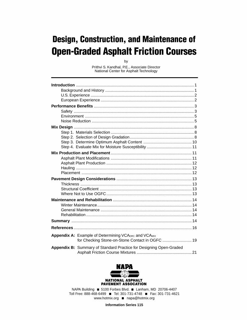
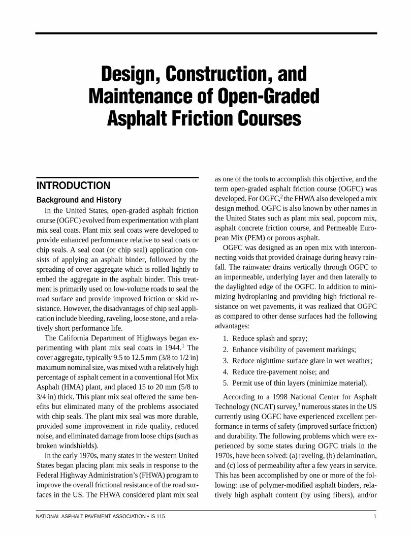
relatively open gradations. The survey3 also concludedthat good design and construction practice was the keyto improved performance of OGFC mixes. Figures 1and 2 show good examples of in-service OGFC pave-ments in Washington and Nevada, respectively.
U.S. ExperienceThe Oregon Department of Transportation (DOT) has
been using OGFC on its highway system since the late1970s. OGFC has become their preferred choice for asurface course due to its excellent performance. Morethan 3000 km (2000 lane miles) of Oregon highwaysare paved with OGFC. Class F, OGFC mix has a nomi-nal maximum aggregate size of 25 mm (1 in) and isgenerally used with a thickness of 50 mm (2 in).
The Washington State DOT had placed more than386,000 tons of OGFC by the end of 1993. In addition ,OGFC is extensively used in California and Nevada.Washington and California use 20 mm (3/4 in) and Or-egon uses 50 mm (2 in) thickness of OGFC.
Arizona and Florida are using OGFC extensively oninterstate and non-interstate pavements. Georgia requiresthe use of OGFC on all interstate highways. It is usu-ally placed 20 mm (3/4 in) in thickness.
Specifications and mix design methods (described later)have now been developed based on research conductedby NCAT and experience gained in the US and Europe.4, 5
European ExperienceAfter OGFC was developed in the US in the early
1970s, it has been increasingly used in many Europeancountries. It is called porous asphalt in Europe. It isfrequently used in Germany, Netherlands, France,Italy, United Kingdom, Belgium, Spain, Switzerland,and Austria.
Unlike the OGFC used in the US in the 1970s, theporous asphalt evolved in Europe with coarser grada-tion, higher in-place air voids (generally between 17 to22 percent range) and, therefore, higher permeabil-ity, and generally placed in thicknesses of 40 to 50 mm(1 1/2 to 2 in). Nominal maximum aggregate size rangesfrom 11 mm (7/16 in) to 16 mm (5/8 in). Smaller andlarger size aggregates are used less frequently. Poly-mer modified binders or fibers, and sometimes both, areused in the OGFC mixtures to obtain thick and strongbinder film thus maximizing resistance to aging andraveling.6 OGFC is used successfully in Europe in afull range of climate, from hot and dry to cold and wet.
There were some 400,000 m2 of OGFC on Germanfederal roads in 1992. Although eight years old, theseOGFC pavements were in excellent condition in 1992.
The primary reason for using OGFC in the Nether-lands was for noise reduction; the safety aspect wasappreciated more later.
FIGURE 1OGFC on Interstate 5 in Washington
NATIONAL ASPHALT PAVEMENT ASSOCIATION • IS 115 3
PERFORMANCE BENEFITS
The following benefits are derived from the use ofOGFC in terms of safety and environment.
SafetyImproved Wet Pavement Frictional Resistance
The following research conducted in the US, Canada,and Europe clearly indicates the superior wet pavementfrictional resistance of OGFC in comparison to denseHMA and portland cement concrete (PCC) surfaces. Theresulting reduction in wet weather accidents has alsobeen documented.
The Bureau of Public Roads (now the Federal High-way Administration) tested the frictional resistance of15 OGFC projects at 40 and 50 miles per hour with askid trailer in the summer of 1967.7 Frictional resistance(expressed as friction number) of a pavement surfacedecreases as the speed is increased. The rate of decreaseof frictional number (FN) per mile increase in the speedis called friction gradient, which is mix specific. Obvi-ously a low friction gradient is desirable. The averageloss in frictional resistance from 40 to 50 mph was onlyone FN point for OGFC in this study. This would give afriction gradient of 0.1 FN per mile per hour. This isconsiderably lower than dense-graded HMA surfaces.
In other words, the OGFC would be far superior to theother dense pavement surfaces at a design speed of 60mph if both had the same FN measured at the usual test-ing speed of 40 mph.
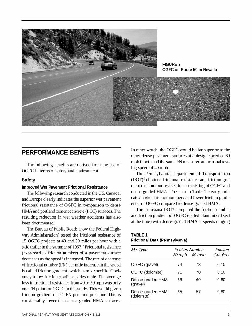
The Pennsylvania Department of Transportation(DOT)8 obtained frictional resistance and friction gra-dient data on four test sections consisting of OGFC anddense-graded HMA. The data in Table 1 clearly indi-cates higher friction numbers and lower friction gradi-ents for OGFC compared to dense-graded HMA.
The Louisiana DOT9 compared the friction numberand friction gradient of OGFC (called plant mixed sealat the time) with dense-graded HMA at speeds ranging
FIGURE 2OGFC on Route 50 in Nevada
TABLE 1Frictional Data (Pennsylvania)
Mix Type Friction Number Friction30 mph 40 mph Gradient
OGFC (gravel) 74 73 0.10
OGFC (dolomite) 71 70 0.10
Dense-graded HMA 68 60 0.80(gravel)
Dense-graded HMA 65 57 0.80(dolomite)
4 NATIONAL ASPHALT PAVEMENT ASSOCIATION • IS 115
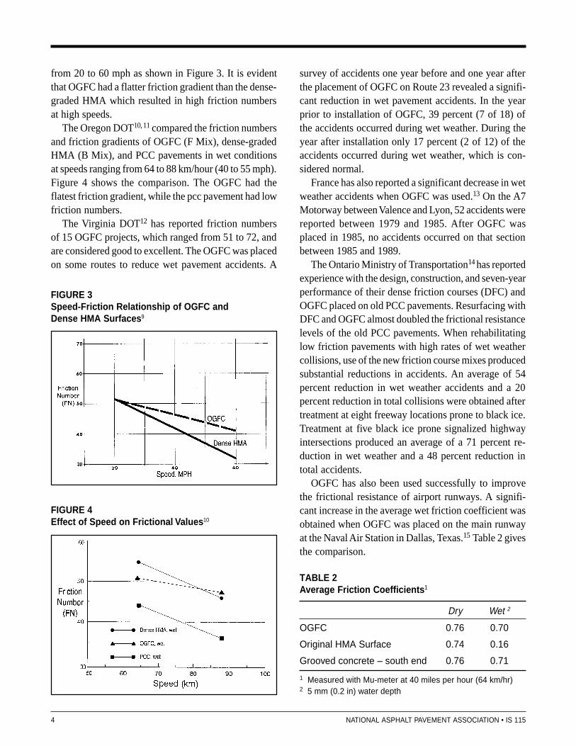
from 20 to 60 mph as shown in Figure 3. It is evidentthat OGFC had a flatter friction gradient than the dense-graded HMA which resulted in high friction numbersat high speeds.
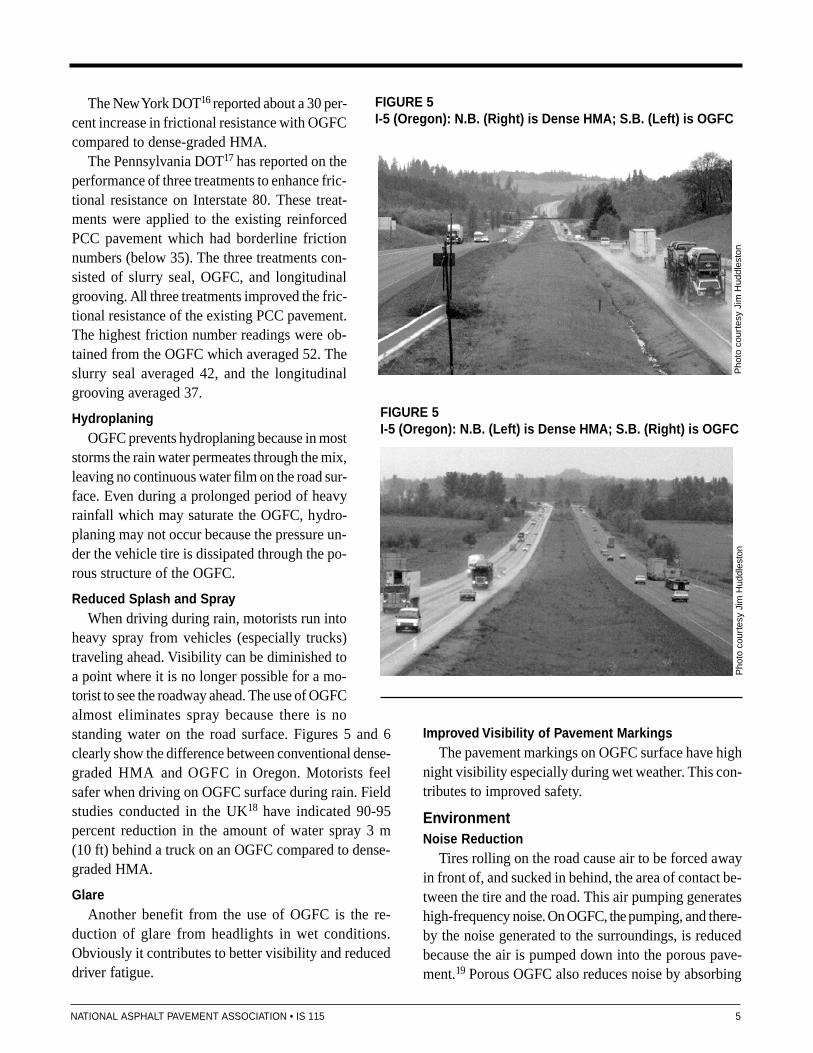
The Oregon DOT10, 11 compared the friction numbersand friction gradients of OGFC (F Mix), dense-gradedHMA (B Mix), and PCC pavements in wet conditionsat speeds ranging from 64 to 88 km/hour (40 to 55 mph).Figure 4 shows the comparison. The OGFC had theflatest friction gradient, while the pcc pavement had lowfriction numbers.
The Virginia DOT12 has reported friction numbersof 15 OGFC projects, which ranged from 51 to 72, andare considered good to excellent. The OGFC was placedon some routes to reduce wet pavement accidents. A
survey of accidents one year before and one year afterthe placement of OGFC on Route 23 revealed a signifi-cant reduction in wet pavement accidents. In the yearprior to installation of OGFC, 39 percent (7 of 18) ofthe accidents occurred during wet weather. During theyear after installation only 17 percent (2 of 12) of theaccidents occurred during wet weather, which is con-sidered normal.
France has also reported a significant decrease in wetweather accidents when OGFC was used.13 On the A7Motorway between Valence and Lyon, 52 accidents werereported between 1979 and 1985. After OGFC wasplaced in 1985, no accidents occurred on that sectionbetween 1985 and 1989.
The Ontario Ministry of Transportation14 has reportedexperience with the design, construction, and seven-yearperformance of their dense friction courses (DFC) andOGFC placed on old PCC pavements. Resurfacing withDFC and OGFC almost doubled the frictional resistancelevels of the old PCC pavements. When rehabilitatinglow friction pavements with high rates of wet weathercollisions, use of the new friction course mixes producedsubstantial reductions in accidents. An average of 54percent reduction in wet weather accidents and a 20percent reduction in total collisions were obtained aftertreatment at eight freeway locations prone to black ice.Treatment at five black ice prone signalized highwayintersections produced an average of a 71 percent re-duction in wet weather and a 48 percent reduction intotal accidents.
OGFC has also been used successfully to improvethe frictional resistance of airport runways. A signifi-cant increase in the average wet friction coefficient wasobtained when OGFC was placed on the main runwayat the Naval Air Station in Dallas, Texas.15 Table 2 givesthe comparison.
FIGURE 3Speed-Friction Relationship of OGFC andDense HMA Surfaces9
FIGURE 4Effect of Speed on Frictional Values10
TABLE 2Average Friction Coefficients1
Dry Wet 2
OGFC 0.76 0.70
Original HMA Surface 0.74 0.16
Grooved concrete – south end 0.76 0.71
1 Measured with Mu-meter at 40 miles per hour (64 km/hr)2 5 mm (0.2 in) water depth
NATIONAL ASPHALT PAVEMENT ASSOCIATION • IS 115 5
The New York DOT16 reported about a 30 per-cent increase in frictional resistance with OGFCcompared to dense-graded HMA.
The Pennsylvania DOT17 has reported on theperformance of three treatments to enhance fric-tional resistance on Interstate 80. These treat-ments were applied to the existing reinforcedPCC pavement which had borderline frictionnumbers (below 35). The three treatments con-sisted of slurry seal, OGFC, and longitudinalgrooving. All three treatments improved the fric-tional resistance of the existing PCC pavement.The highest friction number readings were ob-tained from the OGFC which averaged 52. Theslurry seal averaged 42, and the longitudinalgrooving averaged 37.
HydroplaningOGFC prevents hydroplaning because in most
storms the rain water permeates through the mix,leaving no continuous water film on the road sur-face. Even during a prolonged period of heavyrainfall which may saturate the OGFC, hydro-planing may not occur because the pressure un-der the vehicle tire is dissipated through the po-rous structure of the OGFC.
Reduced Splash and SprayWhen driving during rain, motorists run into
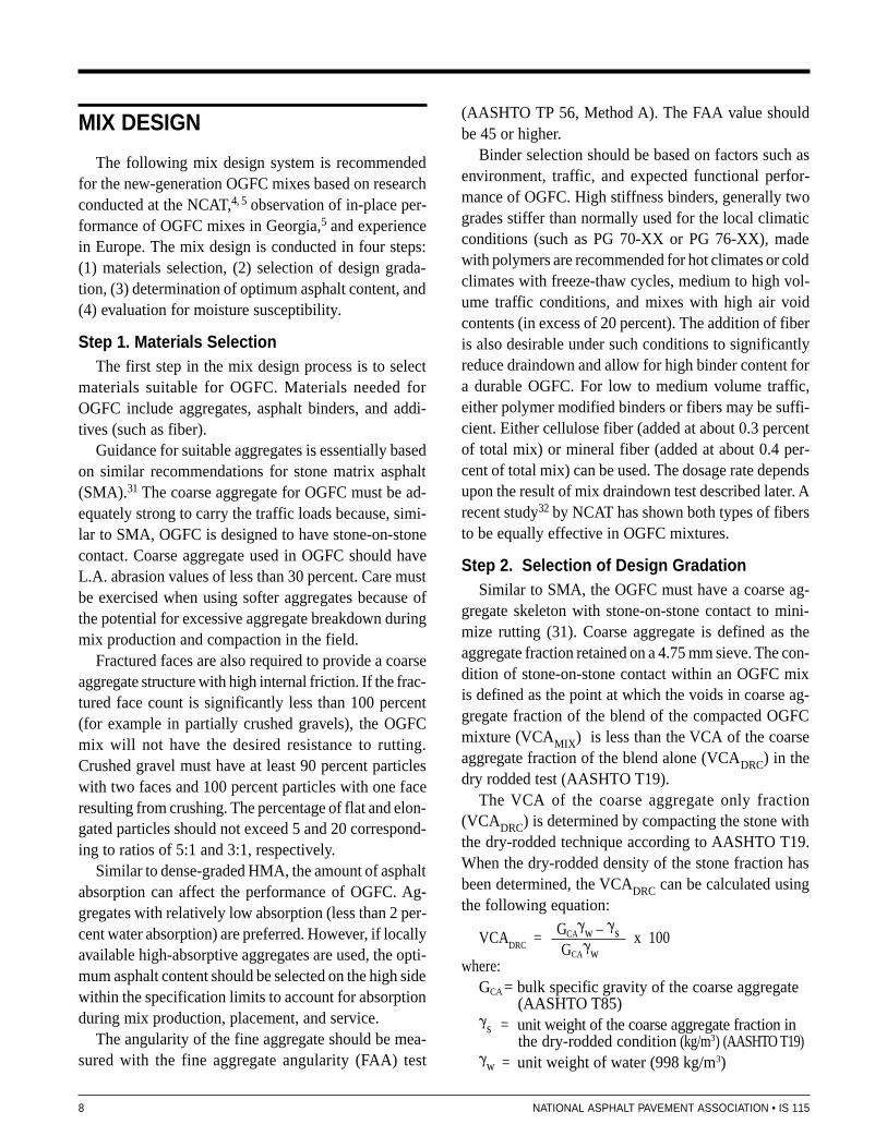
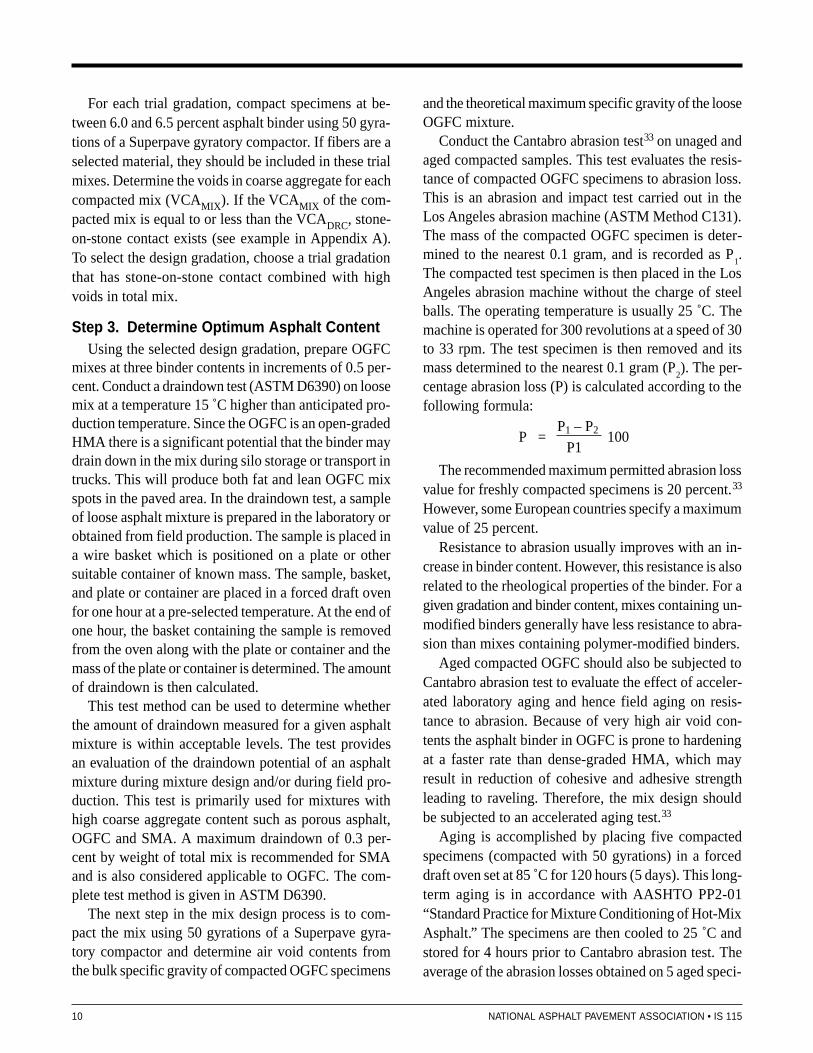
heavy spray from vehicles (especially trucks)traveling ahead. Visibility can be diminished toa point where it is no longer possible for a mo-torist to see the roadway ahead. The use of OGFCalmost eliminates spray because there is nostanding water on the road surface. Figures 5 and 6clearly show the difference between conventional dense-graded HMA and OGFC in Oregon. Motorists feelsafer when driving on OGFC surface during rain. Fieldstudies conducted in the UK18 have indicated 90-95percent reduction in the amount of water spray 3 m(10 ft) behind a truck on an OGFC compared to dense-graded HMA.
GlareAnother benefit from the use of OGFC is the re-
duction of glare from headlights in wet conditions.Obviously it contributes to better visibility and reduceddriver fatigue.
FIGURE 5I-5 (Oregon): N.B. (Right) is Dense HMA; S.B. (Left) is OGFC
Pho
to c
ourt
esy
Jim
Hud
dles
ton
FIGURE 5I-5 (Oregon): N.B. (Left) is Dense HMA; S.B. (Right) is OGFC
Pho
to c
ourt
esy
Jim
Hud
dles
ton
Improved Visibility of Pavement MarkingsThe pavement markings on OGFC surface have high
night visibility especially during wet weather. This con-tributes to improved safety.
EnvironmentNoise Reduction
Tires rolling on the road cause air to be forced awayin front of, and sucked in behind, the area of contact be-tween the tire and the road. This air pumping generateshigh-frequency noise. On OGFC, the pumping, and there-by the noise generated to the surroundings, is reducedbecause the air is pumped down into the porous pave-ment.19 Porous OGFC also reduces noise by absorbing

6 NATIONAL ASPHALT PAVEMENT ASSOCIATION • IS 115
some of the noise emitted by vehicles. On dense sur-faces, the noise emitted towards the pavement is reflectedto the surroundings.
Various research studies have been conducted in theUS and Europe to evaluate the noise reduction capabili-ties of OGFC compared to other pavement surface types.A brief discussion of these studies follows.
The variation of tire/road contact noise (both outsideand inside a car traveling at 80 km/h) within differentsurface types (OGFC, dense-graded HMA, surfacedressing or chip seal, PCC, and stone paving) has beenreported20 as shown in Figure 7. The OGFC had the low-est average and the least variation in noise levels.
Measurements made on dry pavements in the Neth-erlands21 have also shown approximately 3 dB(A) re-duction in noise levels when OGFC is substituted fordense-graded HMA. Effects of noise reduction are gen-erally more pronounced (up to about 8 dB(A)) in wetweather. Measurements were made at speeds of morethan 80 km/hr because the noise produced between thetires and road surface tends to increase at higher speeds.The difference in texture between OGFC and dense-graded HMA not only causes a reduction in noise levelon an OGFC surface, but also produces shifts in thesound spectrum. Less noise is generated and more noiseis absorbed into the relatively open structure of OGFC.The benefits of OGFC in relation to barriers or othernoise abatement methods can readily be quantified.21
The Federal Highway Administration22 conducted acomparative noise level study of OGFC, dense-graded
FIGURE 7Variation of Tire-Pavment Contact Noise (outside andinside a car at 80 km/hour) on Various Surface Types20
HMA, PCC pavement, and chip seal in Arizona, Cali-fornia, and Nevada. It was determined that OGFC hadthe lowest noise level compared to the other pavementsurfaces. The following average sound levels, dB(A),were measured 15 m (50 ft) from the roadway when astation wagon with radial recap tires was operated at105 km/h (65 mph):
OGFC 67Dense-graded HMA 69PCC 70Chip Seal 72
Because of its noise reducing capability, the OGFCis known in Germany as “Fliisterasphalt,” that is “whis-pering” asphalt. A number of full-scale trial sections ofOGFC were constructed between 1986 and 1990 onGerman motorways and trunk roads to investigate thelong-term noise reduction effects of OGFC.23 Reduc-tions in rolling noise of up to 6 dB(A) were measuredand this value has since been adopted as the basis forcalculating the noise reducing properties of OGFC.
Figure 8 shows the reduction in noise levels for bothlight and heavy vehicles when OGFC was substitutedfor dense HMA. This study conducted by the Transpor-tation Research Laboratory in the UK24 also demon-strated that the noise level reductions were maintainedover a long period of time. Compared with hot rolledasphalt surfacings (used in UK) the OGFC was quieterby about 4 decibels in dry conditions and up to 8 deci-bels in the wet condition.25 Compared with broomedPCC surface, the benefit is even more dramatic —a further reduction of 2-3 decibels.
FIGURE 8Reduction in Noise Level when OGFC Substitutedfor Dense HMA24

NATIONAL ASPHALT PAVEMENT ASSOCIATION • IS 115 7
Research in France26 has shown that traffic noise inthe frequency range of 500 to 1500 Hz is reduced tohalf by a 40 mm (1.5 in) thick OGFC. ExperimentalOGFC pavements have been constructed ranging from12.5 mm (0.5 in) to 610 mm (24 in) in thickness in aneffort to determine the optimum layer thickness for noisereduction. It has been found that 40 mm (1.5 in) is neededto get effective noise reduction, and the thicker layerstend to absorb lower frequencies. Since high-pitched,whining noises tend to be the most annoying, the 40mm (1.5 in) thickness is considered to be optimum toreduce noise.26
A joint Nordic project27 found that the noise fromroad traffic can be reduced by 3-5 dB(A) if OGFC isused in lieu of dense-graded HMA. This was observedboth in urban traffic (free flowing traffic at 50-70 km/h)and in highway traffic (70-100 km/h). The quietestOGFC contained a maximum aggregate size of 10-12mm and an air voids content of 22-23 percent.
The mechanism of noise generation and propagationfrom vehicle and tire/road surface has been reported byby the Transport Research Laboratory (TRL)in UK28 Experimental OGFC test sections(containing 20 mm maximum size aggregate)laid on the M1 and M4 motorways reducedthe noise levels by between 5.2 and 6.6 dB(A)compared to conventional asphalt surfaces.28
The Danish Road Institute29 constructedexperimental test sections of OGFC in 1990and 1991 to examine their noise reducing po-tential. Replacement of the existing dense-graded HMA with OGFC resulted in a 4dB(A) reduction in traffic noise at speeds ofabout 50 km/hour. The noise levels of OGFCand dense-graded HMA surfaces were mea-sured annually from 1990 to 1995. After fiveyears, the OGFC still had a noise reduction of3 dB(A) on a highway. The same noise reduc-tion can be achieved by a 50 percent reduc-tion of the traffic volume.30
The Danish government has planned to re-duce the number of dwellings exposed to noiselevels above 65 dB(A) by 66 percent by year2010. Four different pavements were laid in1999 to develop and test two-layer porousasphalt or OGFC as a noise-reducing tool
under Danish conditions. The two-layer porous asphaltwas developed in the Netherlands, where it has beenused since 1990 on urban roads. The bottom layer con-sists of a large aggregate size (11-16 mm). The top layerconsists of a small aggregate size (4-8 mm) to ensure asmooth surface, to reduce the rolling noise, and to keepthe debris from clogging the pores. The large size ag-gregate in the bottom layer ensures that dirt and waterpenetrating the surface can be led away without clog-ging the pores.19
Placing an OGFC overlay may be a viable alterna-tive to the construction of sound barriers to mitigate traf-fic noise. Barriers usually cost between $15 and $20 perlinear foot and generally reduce the noise level by 3 to 5decibels. To reduce the noise level by 3 dB(A), eitherthe traffic volume has to be cut by half or the noise pro-tection distance to the road has to be doubled. Noisebarriers or earth berms have been used for noise re-duction but they are partially effective and do not offerequal noise reduction in every direction as illustratedin Figure 9.27
FIGURE 9Conceptual Differences in the Effectiveness of OGFCand Noise Barriers 27
No improvement forthis part of the building
Noise barrier Noise barrier
Same improvementfor whole building
Quiet road pavement
8 NATIONAL ASPHALT PAVEMENT ASSOCIATION • IS 115
MIX DESIGN
The following mix design system is recommendedfor the new-generation OGFC mixes based on researchconducted at the NCAT,4, 5 observation of in-place per-formance of OGFC mixes in Georgia,5 and experiencein Europe. The mix design is conducted in four steps:(1) materials selection, (2) selection of design grada-tion, (3) determination of optimum asphalt content, and(4) evaluation for moisture susceptibility.
Step 1. Materials SelectionThe first step in the mix design process is to select
materials suitable for OGFC. Materials needed forOGFC include aggregates, asphalt binders, and addi-tives (such as fiber).
Guidance for suitable aggregates is essentially basedon similar recommendations for stone matrix asphalt(SMA).31 The coarse aggregate for OGFC must be ad-equately strong to carry the traffic loads because, simi-lar to SMA, OGFC is designed to have stone-on-stonecontact. Coarse aggregate used in OGFC should haveL.A. abrasion values of less than 30 percent. Care mustbe exercised when using softer aggregates because ofthe potential for excessive aggregate breakdown duringmix production and compaction in the field.
Fractured faces are also required to provide a coarseaggregate structure with high internal friction. If the frac-tured face count is significantly less than 100 percent(for example in partially crushed gravels), the OGFCmix will not have the desired resistance to rutting.Crushed gravel must have at least 90 percent particleswith two faces and 100 percent particles with one faceresulting from crushing. The percentage of flat and elon-gated particles should not exceed 5 and 20 correspond-ing to ratios of 5:1 and 3:1, respectively.
Similar to dense-graded HMA, the amount of asphaltabsorption can affect the performance of OGFC. Ag-gregates with relatively low absorption (less than 2 per-cent water absorption) are preferred. However, if locallyavailable high-absorptive aggregates are used, the opti-mum asphalt content should be selected on the high sidewithin the specification limits to account for absorptionduring mix production, placement, and service.
The angularity of the fine aggregate should be mea-sured with the fine aggregate angularity (FAA) test
(AASHTO TP 56, Method A). The FAA value shouldbe 45 or higher.
Binder selection should be based on factors such asenvironment, traffic, and expected functional perfor-mance of OGFC. High stiffness binders, generally twogrades stiffer than normally used for the local climaticconditions (such as PG 70-XX or PG 76-XX), madewith polymers are recommended for hot climates or coldclimates with freeze-thaw cycles, medium to high vol-ume traffic conditions, and mixes with high air voidcontents (in excess of 20 percent). The addition of fiberis also desirable under such conditions to significantlyreduce draindown and allow for high binder content fora durable OGFC. For low to medium volume traffic,either polymer modified binders or fibers may be suffi-cient. Either cellulose fiber (added at about 0.3 percentof total mix) or mineral fiber (added at about 0.4 per-cent of total mix) can be used. The dosage rate dependsupon the result of mix draindown test described later. Arecent study32 by NCAT has shown both types of fibersto be equally effective in OGFC mixtures.
Step 2. Selection of Design GradationSimilar to SMA, the OGFC must have a coarse ag-
gregate skeleton with stone-on-stone contact to mini-mize rutting (31). Coarse aggregate is defined as theaggregate fraction retained on a 4.75 mm sieve. The con-dition of stone-on-stone contact within an OGFC mixis defined as the point at which the voids in coarse ag-gregate fraction of the blend of the compacted OGFCmixture (VCAMIX) is less than the VCA of the coarseaggregate fraction of the blend alone (VCADRC) in thedry rodded test (AASHTO T19).
The VCA of the coarse aggregate only fraction(VCADRC) is determined by compacting the stone withthe dry-rodded technique according to AASHTO T19.When the dry-rodded density of the stone fraction hasbeen determined, the VCADRC can be calculated usingthe following equation:
VCADRC = GCA�w – �s x 100
GCA�w
where:GCA
= bulk specific gravity of the coarse aggregate (AASHTO T85)
�s = unit weight of the coarse aggregate fraction in
the dry-rodded condition (kg/m3) (AASHTO T19)�w = unit weight of water (998 kg/m3)

NATIONAL ASPHALT PAVEMENT ASSOCIATION • IS 115 9
An example of determining VCADRC and VCAMIX (ofthe compacted OGFC mixture) is given in Appendix A.
The conceptual differences between VCADRC, VCAMIX,and VMA are explained in Figure 10.
The master gradation band given in Table 3 is rec-ommended.
Selection of the design gradation should entail blend-ing selected aggregate stockpiles to produce three trialblends. It is suggested that the three trial gradations fallalong the coarse and fine limits of the gradation rangealong with one falling in the middle. For each trial gra-dation, determine the dry-rodded voids in coarse aggre-gate of the coarse aggregate fraction (VCADRC) usingAASHTO T19.
TABLE 3Recommended Gradation for OGFC
Sieve Percent Passing
19 mm 100
12.5 mm 85-100
9.5 mm 35-60
4.75 mm 10-25
2.36 mm 5-10
0.075 mm 2-4
FIGURE 10Conceptual Differences between VCADRC, VCAMIX, and VMA
Figure A: VCADRC is obtained from the DryRodded Unit Weight of just thecoarse aggregate.
Figure B: VCAMIX is calculated to includeeverything in the mix except thecoarse aggregate.
Figure C: VMA includes everything in themix except the aggregate (bothcoarse and fine). For the VCAMIX
and VMA calculations, asphaltabsorbed into the aggregate isconsidered part of the aggregate.
Figure A
Figure B Figure C
30-40%of VolumeVCADRC
▲
▼
VMAVCAMIX
▲
▼
Dry RoddedUnit Weight
Fine plus CoarseAggregate
EffectiveAsphalt Content
EffectiveAsphalt Content▼
▲
10 NATIONAL ASPHALT PAVEMENT ASSOCIATION • IS 115
For each trial gradation, compact specimens at be-tween 6.0 and 6.5 percent asphalt binder using 50 gyra-tions of a Superpave gyratory compactor. If fibers are aselected material, they should be included in these trialmixes. Determine the voids in coarse aggregate for eachcompacted mix (VCAMIX). If the VCAMIX of the com-pacted mix is equal to or less than the VCADRC, stone-on-stone contact exists (see example in Appendix A).To select the design gradation, choose a trial gradationthat has stone-on-stone contact combined with highvoids in total mix.
Step 3. Determine Optimum Asphalt ContentUsing the selected design gradation, prepare OGFC
mixes at three binder contents in increments of 0.5 per-cent. Conduct a draindown test (ASTM D6390) on loosemix at a temperature 15 ˚C higher than anticipated pro-duction temperature. Since the OGFC is an open-gradedHMA there is a significant potential that the binder maydrain down in the mix during silo storage or transport intrucks. This will produce both fat and lean OGFC mixspots in the paved area. In the draindown test, a sampleof loose asphalt mixture is prepared in the laboratory orobtained from field production. The sample is placed ina wire basket which is positioned on a plate or othersuitable container of known mass. The sample, basket,and plate or container are placed in a forced draft ovenfor one hour at a pre-selected temperature. At the end ofone hour, the basket containing the sample is removedfrom the oven along with the plate or container and themass of the plate or container is determined. The amountof draindown is then calculated.
This test method can be used to determine whetherthe amount of draindown measured for a given asphaltmixture is within acceptable levels. The test providesan evaluation of the draindown potential of an asphaltmixture during mixture design and/or during field pro-duction. This test is primarily used for mixtures withhigh coarse aggregate content such as porous asphalt,OGFC and SMA. A maximum draindown of 0.3 per-cent by weight of total mix is recommended for SMAand is also considered applicable to OGFC. The com-plete test method is given in ASTM D6390.
The next step in the mix design process is to com-pact the mix using 50 gyrations of a Superpave gyra-tory compactor and determine air void contents fromthe bulk specific gravity of compacted OGFC specimens
and the theoretical maximum specific gravity of the looseOGFC mixture.
Conduct the Cantabro abrasion test33 on unaged andaged compacted samples. This test evaluates the resis-tance of compacted OGFC specimens to abrasion loss.This is an abrasion and impact test carried out in theLos Angeles abrasion machine (ASTM Method C131).The mass of the compacted OGFC specimen is deter-mined to the nearest 0.1 gram, and is recorded as P
1.
The compacted test specimen is then placed in the LosAngeles abrasion machine without the charge of steelballs. The operating temperature is usually 25 ˚C. Themachine is operated for 300 revolutions at a speed of 30to 33 rpm. The test specimen is then removed and itsmass determined to the nearest 0.1 gram (P
2). The per-
centage abrasion loss (P) is calculated according to thefollowing formula:
P = P1 – P2 100
P1
The recommended maximum permitted abrasion lossvalue for freshly compacted specimens is 20 percent.33
However, some European countries specify a maximumvalue of 25 percent.
Resistance to abrasion usually improves with an in-crease in binder content. However, this resistance is alsorelated to the rheological properties of the binder. For agiven gradation and binder content, mixes containing un-modified binders generally have less resistance to abra-sion than mixes containing polymer-modified binders.
Aged compacted OGFC should also be subjected toCantabro abrasion test to evaluate the effect of acceler-ated laboratory aging and hence field aging on resis-tance to abrasion. Because of very high air void con-tents the asphalt binder in OGFC is prone to hardeningat a faster rate than dense-graded HMA, which mayresult in reduction of cohesive and adhesive strengthleading to raveling. Therefore, the mix design shouldbe subjected to an accelerated aging test.33
Aging is accomplished by placing five compactedspecimens (compacted with 50 gyrations) in a forceddraft oven set at 85 ̊ C for 120 hours (5 days). This long-term aging is in accordance with AASHTO PP2-01“Standard Practice for Mixture Conditioning of Hot-MixAsphalt.” The specimens are then cooled to 25 ˚C andstored for 4 hours prior to Cantabro abrasion test. Theaverage of the abrasion losses obtained on 5 aged speci-

NATIONAL ASPHALT PAVEMENT ASSOCIATION • IS 115 11
mens should not exceed 30 percent, while no individualresult should exceed 50 percent.
The laboratory permeability testing (ASTM PS 129)of compacted OGFC specimens is optional. Laboratorypermeability values greater than 100 m/day are recom-mended. The optimum asphalt binder content is selectedwhen the OGFC mixture meets the following criteria:1. Air Voids. A minimum of 18 percent is acceptable,
although higher values are desirable. The higher theair voids are, the more permeable the OGFC.
2. Abrasion Loss on Unaged Specimens. The abra-sion loss from the Cantabro test should not exceed20 percent.
3. Abrasion Loss on Aged Specimens. The abrasionloss from the Cantabro test should not exceed 30percent.
4. Draindown. The maximum draindown should notexceed 0.3 percent by total mixture mass.
If none of the binder contents tested meet all fourcriteria, remedial action will be necessary. Air voidswithin OGFC are controlled by the binder content andaggregate gradation. If air voids are too low, the asphaltbinder content should be reduced. If the abrasion losson unaged specimens is greater than 20 percent, moreasphalt binder is needed. Abrasion loss values of agedspecimens in excess of 30 percent can be remedied byeither increasing the binder content or changing the typeof binder additive. If draindown values are in excess of0.3 percent, the amount of binder and/or type of binderor fiber additive can be adjusted. Fiber stabilizers aretypically incorporated into the mix at a rate of 0.2 to 0.5percent by weight of the total mix.
Step 4. Evaluate Mix for Moisture SusceptibilityThe mix designed with Steps 1 through 3 should be
evaluated for moisture susceptibility using the modifiedLottman method (AASHTO T283) with five freeze/thawcycles in lieu of one cycle. The retained tensile strength(TSR) should be at least 80 percent. The AASHTO T283should be modified as follows: (a) specimens compactedwith 50 gyrations of SGC should be used, (b) apply apartial vacuum of 26 inches Hg for 10 minutes to satu-rate the compacted specimens to whatever saturationlevel is achieved, and (c) keep the specimens submergedin water during freeze cycles to maintain saturation.
A summary of recommended standard practice fordesigning OGFC mixtures is given in Appendix B.
MIX PRODUCTION ANDPLACEMENT
There are some significant differences between theprocedures of producing and placing OGFC and con-ventional HMA mixtures. Specific modifications mustbe made to standard HMA production facilities equip-ment, plant operations, and field construction tech-niques.31. 34. 35
Asphalt Plant ModificationsThe main modification required to a standard HMA
production facility is the addition of a mineral fiber orcellulose fiber feed device. Typical dosage rates are 0.4percent for mineral fiber and 0.3 percent for cellulosefiber by total mixture mass. Generally, fibers can be pro-duced in two forms: loose fibers and pelletized fiber.Fibers in a dry, loose state are supplied packaged in plas-tic bags or in bulk. Both fiber types have been addedsuccessfully into batch or drum plants.
In case of a batch plant, the packaged loose fiber isadded to the pugmill during each dry mix cycle. Thebags are carried to the pugmill platform by the use of aconveyor belt. In this rather labor intensive method, theworkers throw an appropriate number of bags into thepugmill. The bags melt and the fiber is thoroughly mixedwith heated aggregate during the dry mix cycle.31
Loose fibers can also be blown into the weigh hop-per or pugmill of a batch plant at the appropriate time.Machines typically designed and supplied by the fibermanufacturers are used. The dry, loose fiber is fed intothe hopper of the machine where it is fluffed by largepaddles. The fluffed fiber enters into an auger systemwhich conditions the material to a known density. Themachine then meters the fiber by mass or volume andblows it into the weigh hopper or pugmill. The samefiber blowing method can also be used in a drum plantby simply blowing the fiber continuously into the drum.The fiber line should be placed within one foot upstreamof the asphalt binder line so that the fibers are capturedby the asphalt binder before getting exposed to the highvelocity gases in the drum. If the fiber is carried by thegas stream it will enter the dust control system of theplant.31
The pelletized form of fibers can be used in both batchand drum plants. The pellets contain a given amount of

12 NATIONAL ASPHALT PAVEMENT ASSOCIATION • IS 115
asphalt binder (to bind the fibers) that must be accountedfor in the total asphalt content of the HMA mixture.The pelletized fiber is placed in a hopper from where itis metered and conveyed to the pugmill of a batch plantor to the drum of a drum plant. The pellets are mixedwith heated aggregate thus melting the asphalt binderand allowing the fiber to mix with the aggregate.31
It is very important that the fiber addition, whether itis bulk or pelletized, be calibrated to ensure the consis-tency of the fiber content in the mix. Fat spots are likelyto result on the surface of the finished OGFC pavementif the fiber is not thoroughly dispersed in the mix and/orthe fiber content is not controlled.
Asphalt Plant ProductionWhen mineral fibers or cellulose fibers are used in
OGFC mixtures, it is necessary to increase both the drymixing time and the wet mixing time when using a batchHMA facility.34 This ensures a thorough dispersion offibers during the dry mixing cycle and a uniform coat-ing of all aggregate particles by the asphalt binder dur-ing the wet mixing cycle.
The screening capacity of the screen deck in a batchplant must also be considered. Since the OGFC predomi-nantly consists of a single size aggregate, override ofthe screen deck and hot bins is likely to occur at lowermix production levels compared to conventional HMAmixtures.34
The OGFC mixture should not be stored in surge binsor silos for extended periods of time due to potentialdraindown problems.
HaulingSince the polymer-modified asphalt binder in the
OGFC has a tendency to bond, it is necessary to apply aheavy and thorough coat of an asphalt release agent totruck beds. Also, truck beds should be raised after spray-ing to drain any puddles of the release agent. Thepuddled release agent, if not removed, will cool theOGFC and cause cold lumps in the mix.34
Tarping each load of OGFC is essential to preventexcessive crusting of the mix during transportation. Thecold lumps do not break down readily and cause pullsin the mat.34 A long haul distance will compound thisproblem. The Oregon DOT limits the haul distance to56 km (35 miles), with 80 km (50 miles) as the absoluteupper limit.35
The HMA production, hauling, and paving shouldbe coordinated so that paving continues smoothly with-out stops. Too few trucks will cause the paver to stop,thus producing bumps. Too many trucks will cause de-lays in unloading thereby resulting in cooling of theOGFC mix and formation of cold lumps.
PlacementThe OGFC should only be placed on an imperme-
able asphalt course unless the pavement is specificallydesigned to be permeable. Otherwise, during rainfall,the water will pass through the OGFC and be trapped inthe underlying pavement layer, resulting in potentialmoisture damage (stripping). A freshly compacteddense-graded HMA course may have as much as 8 per-cent air voids in the mat and thus may be permeable towater. Therefore, it is essential to provide a uniform tackcoat at an adequate application rate to fill and seal thesurface voids of the underlying layer. The FHWA sug-gests sealing the underlying pavement by applying a 50percent diluted slow-setting emulsion tack coat at a rateof 0.05 to 0.10 gallon per square yard.36 The applica-tion rate should be high enough to completely fill thesurface voids. A slow-setting emulsion tack coat is likelyto penetrate the surface voids more effectively than anasphalt cement tack coat. Most dense-graded HMA sur-faces become reasonably impervious after two to threeyears of traffic. Such surfaces will not need any sealingprior to placing OGFC. The OGFC mat should bedaylighted on the shoulder so that rain water percolat-ing through the OGFC can drain out freely at its edge.
The use of a remixing material transfer device fortransferring the OGFC from the trucks to the paver isoptional, but highly recommended.34 It remixes mostcold lumps produced during transportation, and alsoallows continuous operation of the paver for smoothersurfaces.
Conventional asphalt pavers are used to place theOGFC. However, a hot screed is very important to pre-vent pulling of the mat. A propane torch can be used toheat the screed before each use.34
Conventional steel wheel rollers are used to compactthe OGFC. No pneumatic tire rolling is required. It iscritical to keep the roller within 15 m (50 ft) of the paverto compact the OGFC while it is still hot and workable.The breakdown roller usually completes one to two com-plete coverages of the mat in static mode to compact a

NATIONAL ASPHALT PAVEMENT ASSOCIATION • IS 115 13
thin lift (20 mm or 3/4 in) OGFC. The breakdown rollermay have to be operated in a vibratory mode at trans-verse joints and occasionally longitudinal joints to helpknock down a high joint. Generally, use of vibratorycompaction should be discouraged.
OGFC containing polymer modified asphalt binder(especially containing fiber too) is an extremely harshmix and does not lend itself to raking unlike conven-tional HMA. Raking, if attempted, produces rough ar-eas with excessive voids in the finished mat. Therefore,it is very important to have the entire screed heated wellto avoid any raking.
Longitudinal joints in the OGFC pavement are con-structed by placing the mix approximately 1.5 mm (1/16in) above the previously placed and compacted lane.Therefore, it is important for the edge of the screed orextension to follow the joint exactly to prevent exces-sive overlap. Transverse joints placed against a previ-ously laid OGFC are constructed by starting with thescreed one foot behind the joint and laying the screedflat on the previously laid OGFC mat. The hot OGFCmix is augered in front of the screed and then drug offthe new joint when travel begins. The joint should thenbe cross rolled with a steel wheel breakdown roller.34
PAVEMENT DESIGNCONSIDERATIONS
The following discussion addresses the use of OGFCin pavement structure.
ThicknessIn the US, 20 mm (3/4 in) is a common thickness for
OGFC, although Oregon generally uses 50 mm (2 in).Thicknesses of OGFC generally range from 20 to 50mm in Europe. A thickness of 50 mm is used in Europeto significantly reduce noise levels.
Structural CoefficientThe California Department of Transportation (Caltrans)
conducted a laboratory and field study37 to evaluate thestructural properties of both OGFC and asphalt treatedpermeable base. Laboratory testing included resilientmodulus. The field investigations consisted of Dynaflectmeasurements before and after placement of the layer.
It was recommended to assign the same gravel equiva-lent factor (analogous to structure coefficient) to bothOGFC and permeable base.
The Oregon Department of Transportation uses thesame structural coefficient for OGFC as dense-gradedHMA.11 Deflections taken on OGFC pavements afterbeing placed have shown the estimated deflection re-duction was comparable to that expected from typicaldense-graded HMA overlays of similar thickness.
Where Not To Use OGFC
Long Haul. Jobs with extremely long haul distancesfrom the HMA plant site to project site are not suit-able due to potential draindown and/or cooling of theOGFC mix. Although success has been achieved withone-way haul distances up to 110 km (70 miles), thecurrent policy in Oregon is to restrict haul distance to56 km (35 miles).
Inlays. The OGFC must be allowed to drain by day-lighting the mix on the shoulder. Therefore, it cannotbe used as an inlay pavement layer.
Hand Work. The OGFC mix is very difficult to rake.Don’t place OGFC when there is an abundance of handwork involved on the project. For example, OGFCshould not be specified for tapers, road approaches,or for city streets where there are lots of inlets andmanholes.
Snow Zones. Some problems have been noted in snowzones where extensive snow plowing is required. Theplow blade can catch on the coarse aggregate and maycause raveling in some cases.
Critical Pavement Locations. OGFC may ravel orshove when used at intersections, locations with heavyturning movements, ramp terminals, curbed sections,and other adverse geometric locations.36
Permeable Underlying Layer. Except for the rarelydesigned, full-depth, porous pavement, it is of para-mount importance to place OGFC on an imperme-able pavement course. This allows the water at thebottom of OGFC to flow outwards on the surface ofthe underlying layer rather than penetrating it andcausing moisture damage. If OGFC must be placedover a freshly compacted dense-graded HMA coursewith high air void content, the surface should be sealedas discussed under placement in the last chapter.
14 NATIONAL ASPHALT PAVEMENT ASSOCIATION • IS 115
MAINTENANCE ANDREHABILITATION
Winter MaintenanceWinter maintenance (snow and ice removal) has been
often cited and assumed to be a serious problem withOGFC. However, there has been little difficulty in thisregard in Europe. OGFC has different thermal and ic-ing properties than conventional dense-graded HMA,and needs its own winter maintenance regimen. OGFChas a different thermal conductivity (40 to 70 percentless than dense-graded HMA) and, therefore, acts likean insulating layer. OGFC may have a temperature of2 ˚C lower than dense-graded HMA. Frost and ice willaccumulate earlier, more quickly, and more frequentlyon OGFC compared to other surfaces. Construction oflong, continuous stretches of highways using OGFC isdesirable. Alternate applications of dense-graded HMAand OGFC can present the motoring public with sud-den changes in skid resistance.38
It is important to give special and repeated trainingto drivers of snow-plows and spreaders. “Preventivesalting” of the OGFC at the right time is important. Salt-ing is only successful on a dry pavement when tem-peratures are lower than –10 ˚C. A combination of 70percent dry salt and 30 percent salt water solution (20percent calcium chloride) applied at the rate of 10-20g/m2 has been determined to be effective in Austria.38 Ithas been found in Holland that the use of brine is ex-tremely effective and reduces the salt consumption toonly 15 percent of normal. Brine cannot be used effec-tively on dense surfaces because it would run offquickly.24 According to experience in Netherlands39
about 25 percent more salt is necessary. The timing ofapplication is very important.
Black ice can also form on the OGFC if water is al-lowed to accumulate on curves in the road, and on thetransition areas between OGFC and dense-graded HMA.
General MaintenanceIf a relatively dense-graded OGFC is used, it may
gradually be choked and partially lose permeability.Therefore, frequent cleaning may be necessary. Threemethods of cleaning OGFC: (a) cleaning with a fire hose,(b) cleaning with a high pressure cleaner, and (c) clean-
ing with a specially manufactured cleaning vehicle.These techniques were tested for effectiveness in Swit-zerland (40). The special cleaning vehicle manufacturedby FRIMOKAR of Switzerland40 can wash and vacuumclean the surface in one pass. Deposited dirt in the OGFCis washed out by a high pressure water stream with aworking pressure of about 500 psi from a front washingbeam, mounted on the vehicle. The water-dirt mixtureon the pavement is then sucked into a dirt container bya heavy duty vacuum cleaner. Method (b), cleaning witha high pressure cleaner, was found to be most effectivebased upon permeability tests after cleaning.
If OGFC is placed on airport runways used by jetaircraft, it is necessary to keep the OGFC swept cleanat all times to avoid ingress of loose aggregates into thejet engines.
RehabilitationMost agencies do not apply a dense-graded HMA
over OGFC at the end of its service life. Studies havefound that this will trap water in the OGFC and causedeterioration of the pavement. Generally, it is recom-mended to mill off the existing OGFC prior to replac-ing with a new OGFC or any other HMA course.
SUMMARY
Open-graded friction course (OGFC), also calledporous asphalt in Europe, is an open-graded HMA mix-ture with interconnecting voids that provides drainageduring rainfall. In addition to minimizing hydroplaningduring rainfall, OGFC offers the following advantages:
■ High skid resistance on wet pavements. Researchdata obtained by several agencies indicate signifi-cantly higher skid resistance of OGFC compared todense pavements. The high skid resistance resultsfrom the increased macrotexture of the OGFC sur-face and is also maintained at high operating speeds.
■ Reduced splash and spray. The safety of the mo-toring public is improved due to reduced splash andspray from the vehicles driving ahead.
■ Enhanced visibility of pavement markings. Thesafety of the motoring public is also increased be-cause the visibility of pavement markings on OGFCsurface is enhanced, especially in inclement weather.

NATIONAL ASPHALT PAVEMENT ASSOCIATION • IS 115 15
• Reduced tire-pavement noise. Research data indi-cates a reduction in noise levels up to about 6 dB(A)when OGFC is substituted for dense-graded HMA.
The National Center for Asphalt Technology (NCAT)has developed a new-generation OGFC based upon anNCAT research project, experience of states in the U.S.which have placed durable OGFC pavements, and ex-perience in Europe. This report has covered the follow-ing topics:
■ New Mix Design Method. The mix design is con-ducted using 50 gyrations of a Superpave gyratorycompactor. High quality, angular aggregates areused. High stiffness binders such as PG 76-XX madewith polymers are used in the OGFC. The use ofcellulose or mineral fiber is recommended. The se-lected gradation should be within a recommendedband and should provide stone-on-stone contact inthe coarse aggregate (material retained on 4.75 mmsieve). The optimum asphalt content for the selectedOGFC gradation is established to meet the follow-ing criteria: (a) 18 percent minimum air voids; (b)abrasion loss from the Cantabro test (conducted in aLos Angeles abrasion machine) not to exceed 20percent for unaged compacted specimens and 30percent for aged specimens; (c) draindown not toexceed 0.3 percent; and (d) the retained tensilestrength of the compacted specimens subjected tofive freeze/thaw cycles in modified Lottman method(AASHTO T283) should be at least 80 percent.
■ Mix Production and Placement. The primary modi-fication required for a standard HMA facility is theaddition of a fiber feed device. The method of incor-porating both loose or pelletized fibers has been de-scribed. Both dry and wet mixing times need to beincreased to obtain good dispersion of fibers andgood coating of aggregate particles.
The OGFC mix should be protected from coolingduring transportation to minimize cold lumps which maycause pulls in the mat during paving. The use of a re-mixing material transfer device is highly recommendedto obtain a uniform mix and ensure continuous opera-tion of the paver so the newly placed surface is free frombumps. The paver screed must be heated before begin-ning the paving operations to ensure a smooth laydown.The OGFC mix with polymer-modified binder andfiber is a very harsh mix and cannot be raked easily.Avoid handwork if possible.
Use conventional steel rollers in static mode. One totwo complete passes over the mat are sufficient to com-pact a thin lift (20 mm) of OGFC.
■ Pavement Design Considerations. A thickness of20 mm (3/4 in) is most commonly used in the U.S.for OGFC, except Oregon which uses 50 mm (2 in).At least 50 mm thickness is used to cause signifi-cant reduction in noise levels. The Oregon Depart-ment of Transportation uses the same structuralcoefficient for OGFC as dense-graded HMA basedon a study using deflection measurements.
■ Maintenance and Rehabilitation. The report de-scribes procedures for snow and ice control onOGFC pavements. Undertaking “preventive salting”of the OGFC at the right time is important. At theend of its service life, OGFC should be milled offprior to replacing with a new OGFC or any other
HMA course

16 NATIONAL ASPHALT PAVEMENT ASSOCIATION • IS 115
1. Huber, G. Performance Survey on Open-Graded Friction Course Mixes. TRB, Synthesis of HighwayPractice 284, 2000.
2. Smith, R.W., J.M. Rice, and S.R. Spelman. Design of Open-Graded Asphalt Friction Courses.Report FHWA-RD-74-2, Federal Highway Administration, January 1974.
3. Kandhal, P.S., and R.B. Mallick. Open-Graded Friction Course: State of the Practice. TransportationResearch Circular E-C005, TRB, December 1998.
4. Kandhal, P.S. and R.B. Mallick. Design of New-Generation Open-Graded Friction Courses.National Center for Asphalt Technology, Research Report 99-3, December 1999.
5. Mallick, R.B., P.S. Kandhal, L.A. Cooley, and D.E. Watson. “Design, Construction, and Performanceof New-Generation Open-Graded Friction Courses.” Asphalt Paving Technology, Vol. 69, 2000.
6. Tappeiner, W.J. Open-Graded Asphalt Friction Course. Information Series 115, NAPA, March 1993.
7. Hewett, J.W. “Open-Graded, Plant-Mixed Seals.” Highway Research Record 300, 1970.
8. Brunner, R.J. Open-Graded Asphalt Friction Course. Pennsylvania DOT Research Project 74-8,February 1975.
9. Adam, V. and S.C. Shah. “Evaluation of Open-Graded Plant Mix Seal Surfaces for Correction ofSlippery Pavements.” Louisiana Dept. of Highways. Paper presented at 53rd Annual Meetingof Highway Research Board, January 1974.
10. Huddleston, I.J., H. Zhou, and R.G. Hicks. “Evaluation of Open-Graded Asphalt Concrete MixturesUsed in Oregon.” Transportation Research Record 1427, 1993.
11. Scott, K., J. Gower, R.G. Hicks, and D.F. Rogge. “Overview on Use of Porous Asphalt Pavementsin Oregon.” Asphalt Paving Technology, Volume 69, 2000.
12. Maupin, G.W. “Virginia’s Experience with Open-Graded Surface Mix.” Paper presented to theTransportation Research Board, January 1976.
13. Chaignon, F. “Porous Asphalt in France.” The Asphalt Year Book, The Institute of Asphalt Technology,U.K., 1993.
14. Kamel, N. and G.R. Musgrove. “Design and Performance of Bituminous Friction Course Mixesin Ontario.” Tribune DE L’ARTC, Vol. 5, No. 3, 1981.
15. Jones, M.P. “Friction Overlay Improves Runway Skid Resistance.” Civil Engineering – ASCE, March 1973.
16. “Open-Graded Asphalt Gives 30% Greater Skid Protection.” Better Roads, March 1975.
17. Brunner, R.J. and D.B. Mellott. Skid Resistance Treatments on I-80. Pennsylvania Dept. of Transportation,Research Project 75-9, December 1976.
18. Nicholls, J.C. Review of UK Porous Asphalt Trials. TRL Report 264, Transportation Research Laboratory,London, U.K., 1997.
19. “Noise-Reducing Pavements for Urban Roads.” Nordic Road & Transport Research, No. 3, 1999.
20. “Open Graded Asphalt – Conclusions from PIARC Publication “Porous Asphalt” (1993).” Asphalt Review,Vol. 12, No. 4, Australian Asphalt Pavement Association, December 1993.
21. Van der Zwan, T. Goeman, H.J. Gruis, J.H. Swart, and R.H. Oldenburger. “Porous Asphalt Wearing Coursesin the Netherlands: State of the Art.” Transportation Research Record 1265, 1990.
REFERENCES
NATIONAL ASPHALT PAVEMENT ASSOCIATION • IS 115 17
22. Kay, R.A. and J.K. Stephens. “Porous Friction Courses and Roadway Surface Noise.” Federal HighwayAdministration, Implementation Package, March 1975.
23. Schmitt, E. “Winter Maintenance on Porous Asphalt.” The European Asphalt Magazine, Volume 2,European Asphalt Pavement Association, 1994.
24. Fabb, T.R.J. “The Case for the Use of Porous Asphalt in the U.K.” The Asphalt Year Book, The Instituteof Asphalt Technology, U.K., 1993.
25. Daines, M.E. “Trials of Porous Asphalt and Rolled Asphalt on the A38 at Burton.” TRRL ResearchReport 323, 1992.
26. Hines, M. “Enrobe Drainant at Montelimar, France.” Koch Materials Company Newsletter, Fall 1993.
27. “Optimum Drainage Asphalt Reduces Noise Emissions.” Nordic Road & Transport Research, Vol. 1, 1994.
28. Nelson, P.M. “Designing Porous Road Surfaces to Reduce Traffic Noise.” Transportation Research Labora-tory, U.K., Annual Review, 1994.
29. “Porous Road Surfaces Reduce Noise.” Nordic Road & Transport Research, No. 3, 1992.
30. “Noise Reduction by Drainage Asphalt.” Nordic Road & Transport Research, Vol. 1, 1997.
31. Brown, E.R. and L.A. Cooley. “Designing Stone Matric Asphalt Mixtures for Rut-Resistant Pavement.”NCHRP Report 425, TRB, 1999.
32. Cooley, L.A., E.R. Brown, and D.E. Watson. “Evaluation of OGFC Mixtures Containing Cellulose Fibers.”NCAT Report 00-05, December 2000.
33. Porous Asphalt. Manual 17, Sabita Ltd., Roggebaai, South Africa, November 1995.
34. APAC – Georgia Inc. “Construction Techniques for Modified OGFC.” NAPA, Hot Mix Asphalt Technology,1996 (page 25).
35. Geistlinger, L. “Open-Graded Friction Courses.” Roads & Bridges, September 1996.
36. “Open Graded Friction Courses.” The Federal Highway Administration Technical Advisory T5040.31,December 26, 1990.
37. Moore, R.L. “Structure Value of Asphalt Treated Permeable Base and Open-Graded Asphalt Concrete.”California Department of Transportation, Report No. FHWA/CA/TL-89/11, October 1989.
38. Weyringer, H.W. “In the Bleak Mid-Winter.” World Highways, January/February 1993.
39. Westerop, A.J.M. “Porous Asphalt in the Netherlands.” The Institute of Asphalt Technology, U.K.,The Asphalt Year Book, 1993.
40. Hiersche, E.U. and Freund, H.J. “Technology and In-Situ Trial of a Noise Absorbing Pavement Structure.”Proceedings, Seventh International Conference on Asphalt Pavement, University of Nottingham, U.K.,August 1992.
41. Kooij Van der and H.A. Verburg. “Mixings of High Penetration Bitumens Duruing Hot Mix Recyclingof Porous Asphalt.” Proceedings of Eurasphalt and Eurobitume, Vol. 3, Strasbourg, France, May 1996.

18 NATIONAL ASPHALT PAVEMENT ASSOCIATION • IS 115

NATIONAL ASPHALT PAVEMENT ASSOCIATION • IS 115 19
TABLE A-1Gradations of the Three Trial Blends
Percent Passing by Volume
Sieve Size (mm) Trial Blend 1 Trial Blend 2 Trial Blend 3
19.0 100 100 100
12.5 95 95 95
9.5 55 65 75
4.75 10 15 25
2.36 5 7 10
0.075 3.0 3.0 3.0
GCA* 2.688 2.688 2.688
* GCA
–coarse aggregate bulk specific gravity
TABLE A-2Unit Weight and VCADRC for the Three Trial Blends
Blend No. VCADRC (%) Dry RoddedUnit Weight, kg/m3
1 41.7 1564.27
2 41.0 1582.75
3 40.3 1601.53
Three trial gradations were selected for evaluation asshown in Table A-1.
Determination of Voids in the Coarse Aggregate —Dry-Rodded Condition (VCADRC)VCA
DRC was determined for three blends of coarse ag-
gregate fractions according to AASHTO T 19. TheVCA
DRC was determined for the aggregate fraction
coarser than the 4.75 mm sieve. Two replicates for eachtest were performed. The average results are given inTable A-2.
The calculation for VCADRC
for blend 1 is shown below.
VCADRC
= G
CA�
w – �
s
x 100 GCA
�w
VCADRC
= (2.688) (998) – 1564.27
x 100 (2.688) (998)
VCADRC = 41.7 %
where,�s = unit weight of the coarse aggregate fraction
in the dry rodded condition (kg/m3)�w = unit weight of water (998 kg/m3), and GCA= combined bulk specific gravity of the coarse
aggregate (Table A-1).
Compact SpecimensFor each of the trial blends, three samples were pro-
duced at 6.0% asphalt binder by total mix mass usingthe Superpave Gyratory Compactor (SGC). The bulkspecific gravities (G
mb) of these specimens were then
determined after compaction according to AASHTOT 166. Also for each trial blend the maximum theoreti-cal specific gravity (G
mm) was determined for one sample
according to AASHTO T 209. The air voids and VCAMIX
were then determined. These results are summarized inTable A-3.
TABLE A-3Test Results for Three Trial Gradation Blends
Property Trial Blend 1 Trial Blend 2 Trial Blend 3
Gmb 1.996 2.007 2.030
Gmm 2.449 2.451 2.455
Air Voids, % 18.5 18.1 17.3
VCAMIX, % 33.2 36.5 43.3
APPENDIX A
Example of Determining VCADRC and VCAMIX
for Checking Stone-on-Stone Contact in OGFC Mixtures
20 NATIONAL ASPHALT PAVEMENT ASSOCIATION • IS 115
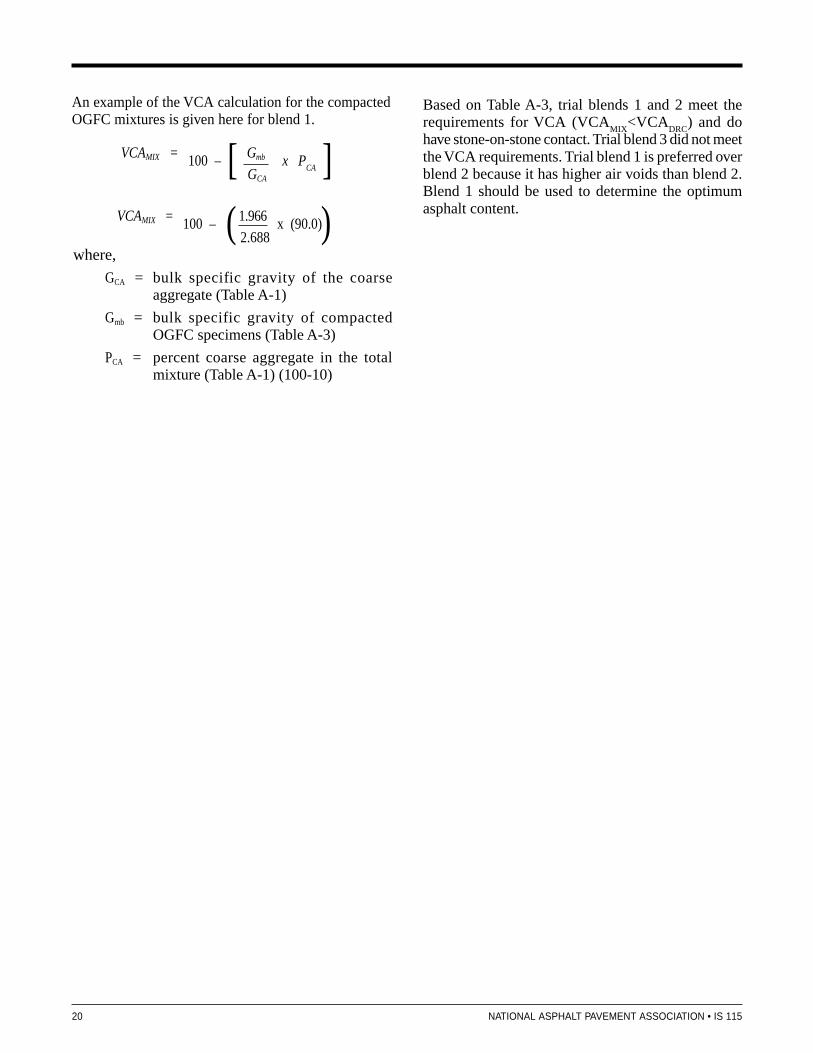
An example of the VCA calculation for the compactedOGFC mixtures is given here for blend 1.
VCAMIX = 100 – 1.966
x (90.0) 2.688
[ ]
( )
VCAMIX = 100 – Gmb
x P
CA GCA
where,
GCA = bulk specific gravity of the coarseaggregate (Table A-1)
Gmb = bulk specific gravity of compactedOGFC specimens (Table A-3)
PCA = percent coarse aggregate in the totalmixture (Table A-1) (100-10)
Based on Table A-3, trial blends 1 and 2 meet therequirements for VCA (VCA
MIX<VCA
DRC) and do
have stone-on-stone contact. Trial blend 3 did not meetthe VCA requirements. Trial blend 1 is preferred overblend 2 because it has higher air voids than blend 2.Blend 1 should be used to determine the optimumasphalt content.

NATIONAL ASPHALT PAVEMENT ASSOCIATION • IS 115 21
Summary of Recommended Practice for DesigningOpen-Graded Friction Course Mixtures
APPENDIX B
The following is an abbreviated outline of the mixdesign procedure contained in the main body of thisreport.
Step 1. Materials SelectionCoarse Aggregates:
• L.A. Abrasion ≤ 30%• Fractured faces ≥ 90% two fractured faces
100% one fractured face• Flat and Elongated ≤ 5% 5:1 ratio
≤ 20% 2:1 ratioFine Aggregate:
• Fine Aggregate Angularity (FAA) ≥ 45
Asphalt Binder:• High stiffness binder generally two grades stiffer
(high temperature designation) than normally usedfor the local climate.
• Polymer modification recommended for mediumto high traffic.
• Fibers recommended to prevent draindown.• For low to medium traffic either polymer modi-
fied binder or fiber may be sufficient
Step 2. Selection of Design Gradation
Recommended Gradation for OGFC
Sieve Percent Passing
19 mm 100
12.5 mm 85-100
9.5 mm 55-75
4.75 mm 10-25
2.36 mm 5-10
0.075 mm 2-4
• Blend selected aggregate stockpiles to producethree trial blends.– One near the coarse side of gradation band– One near the fine side of the gradation band– One near the middle of the gradation band.
• Determine the dry-rodded voids in coarse aggre-gate of the coarse aggregate fraction (VCA
DRC).
Coarse aggregate is defined as the aggregate frac-tion retained on the 4.75 mm sieve.– Compact coarse aggregate according
to AASHTO T19– Calculate VCA
DRC
VCADRC
= G
CA�
w – �
s
x 100 GCA
�w
where,GCA= bulk specific gravity of the coarse
aggregate (AASHTO T85)�s = unit weight of the coarse aggregate
fraction in the dry-rodded condition(kg/m3) (AASHTO T19)
�w = unit weight of water (998 kg/m3)
• For each trial gradation prepare three batches atbetween 6.0 and 6.5 asphalt binder. Include fibersif used.
• Compact two specimens from each trial gradationusing 50 gyrations of the Superpave gyratory com-pactor.– Determine the bulk specific gravity (G
mb) of
each specimen.– Determine the VCA
MIX each compacted
specimen.
VCAMIX
= 100 – Gmb
x PCA GCA
where:GCA = bulk specific gravity of the coarse
aggregate
Gmb = bulk specific gravity of compactedOGFC specimens
PCA = percent coarse aggregate in thetotal mixture
[ ]

22 NATIONAL ASPHALT PAVEMENT ASSOCIATION • IS 115
• Use the remaining sample from each trial grada-tion to determine the Theoretical MaximumSpecific Gravity (G
mm) of each trial.
• Compare VCAMIX
to VCADRC
for each trialgradation.
• To select design gradation, choose trial gradationwith VCA
MIX < VCA
DRC with high air voids.
Step 3. Determine Optimum Asphalt Content
• Using the selected design gradation, prepareOGFC mixes at three binder contents in incrementsof 0.5 percent.
• Conduct draindown test (ASTM D6390) on loosemix at a temperature 15 ̊ C higher than anticipatedproduction temperature.
• Compact mix using 50 gyrations of a Superpavegyratory compactor and determine air void con-tents.
• Conduct the Cantabro abrasion test on unagedand aged (7 days @ 60 ˚C samples.
• The asphalt content that meets the following cri-teria is selected as optimum asphalt content.
Air Voids ≥ 18%Cantabro Abrasion Test (unaged) ≤ 20 %Cantabro Abrasion Test (Aged) ≤ 30 %Draindown ≤ 0.3 %
Step 4. Evaluate Mix for MoistureSusceptibility
• Test final mix for moisture susceptibility usingthe modified Lottman method (AASHTO T283)– Compact using 50 gyrations of Superpave
gyratory compactor– Apply partial vacuum of 26 inches Hg for
10 minutes to whatever saturation is achieved.– Use five freeze/thaw cycles in lieu of
one cycle.– Keep specimens submerged in water during
freeze cycles• Retained tensile strength (TSR) ≥ 80%.

NAPA: THE SOURCEThis publication is one of the many technical, informational, and promotional publications available fromthe National Asphalt Pavement Association (NAPA). To obtain a publications catalog, contact NAPA at:
Publications DepartmentNational Asphalt Pavement Association1500 Forbes Boulevard, Lanham, MD 20706-4407Toll Free: 888-468-6499, Tel: 301-731-4748, Fax: [email protected]

National Asphalt Pavement AssociationNAPA Building5100 Forbes Blvd.Lanham, Maryland [email protected]: 301-731-4748Fax: 301)-731-4621Toll Free: 1-888-468-6499