design considerations for nonclog … pumps, as defined by the hydraulic institute (ansi/hi standard...
TRANSCRIPT

Richard J. Cronin is a Senior Engineerfor Mechanical Solutions, Inc., in Elders-burg, Maryland. He has more than 15 yearsof experience in the design, development,analysis, and troubleshooting of rotatingequipment. While at Ingersoll-DresserPump (Flowserve), he was the leadmechanical design engineer for the de-velopment of their line of submersiblesewage pumps (MSX) and vertical turbinenonclog pumps (QMN). He received three
United States and international patents for work performed onthese developments.
Mr. Cronin has a BSME degree from the University of Marylandat College Park, and he is a registered Professional Engineer in theStates of Virginia and Maryland.
David A. House is a Principal Engineerfor Flowserve Pump Division, in Taney-town, Maryland. He has more than 30years of experience in the application,design, development, analysis, and trou-bleshooting of nonclog and water pumpingequipment. He has been the principalmechanical design engineer for productenhancements to the Flowserve line of drypit nonclog pumps, and he has overseen thedevelopment of many new sizes of dry pit
nonclog pumps (MF and MN) and new sizes of vertical turbinenonclog pumps (QMN) over the past 20 years.
Mr. House has a BSME degree from the University of Marylandat College Park.
Alan C. Miller is the Senior UpgradesEngineer for the Flowserve Pump Division,in Taneytown, Maryland. He has more than34 years of experience dealing with turbo-machinery, especially pumps. His ex-perience includes: test engineering,product engineering and design, qualityassurance, and engineering management.Currently he develops and applies up-grades to customers’ existing pumps,
providing savings in capital and maintenance expense whileincreasing pump life.
Mr. Miller has a BSME from the Pennsylvania State Universityat State College.
ABSTRACT
Nonclog pumps, as defined by the Hydraulic Institute (ANSI/HIStandard 1.3, 2000), are “pumps designed to assure maximumfreedom from clogging when handling liquids containing solids orstringy material.” These pumps are also commonly known as solidshandling or sewage pumps. The category of nonclog pumpsencompasses a broad range of pump sizes and designs representingone of the largest market segments available. This paper focuses oncentrifugal nonclog pumps 3 bhp and greater with a dischargediameter larger than 3 inch. The available types, operation, designelements, materials, driver configuration, and variable speedoperation are presented herein. Typical field problems with theirresolution, vibration analysis, and equipment upgrades are alsodiscussed.
INTRODUCTION
Design
The typical nonclog pump is a single volute with the casing andimpeller designed with wide passages to pass solids. The impelleris overhung on the shaft and the rotating assembly is back pull-outso it may be removed without disturbing the pump casing orsuction head. Nonclog pump designs are available in specificspeeds Ns = 1500 to 5000 with most designs in the range of Ns =2000 to 3500. Flows are available from 100 to 100,000� gpm withheads from 10 ft to 250 ft TDH.
Applications
A nonclog pump is used when the liquid being pumped has theability to adversely affect a pump’s performance through the accu-mulation of problem materials in choke points such as the impellereye and wear rings. The liquid pumped is typically raw or in-process sewage but nonclog pumps can also be found in minedewatering, construction, industrial processes with solids insuspension, raw water intake, and cooling water.
Solid Size
A nonclog pump specification should designate the maximumdiameter of the solid expected to pass through the pump withoutclogging. The minimum solid size diameter accepted as standard by
116
DESIGN CONSIDERATIONS FOR NONCLOG PUMPS
byRichard J. CroninSenior Staff Engineer
Mechanical Solutions Incorporated
Eldersburg, Maryland
David A. HousePrincipal Engineer
andAlan C. Miller
Senior Upgrades Engineer
Flowserve Corporation, Pump Division
Taneytown, Maryland
many US states is 3 inch. By consequence, the minimum nonclogpump size is 3 inch discharge to allow passage of the 3 inchdiameter solid into and out of the pump. The maximum nonclogpump size is limited only by the requirements of the end users whobase their pump sizes on commercially available pipe used in theconstruction of wastewater processing plants. This effectively limitsthe available pumps size to 60 inch discharge diameter. A 60 inchdischarge diameter pump specification is rare and more commonlyseen pump sizes range from 3 inch to 48 inch discharge diameter.
Stringy Material
In addition to passing a minimum diameter solid, a nonclogpump is expected to pass stringy material, rags, other problemsolids such as hair and grease conglomerates, and a minimum of 2percent solids in suspension. That is not to say that nonclog pumpswill not clog if faced with difficult solids they were not designed topass. Should a nonclog pump designed to pass a 3 inch diametersolid be expected to pass a 12 inch long by 3 inch wide rag simplybecause it has little thickness? Of course not since the rag willlikely wrap around the impeller suction vanes tips. The HydraulicInstitute (ANSI/HI Standard 1.3, 2000) recognizes such problemsand recommends comminution and/or adequate bar screens beprovided upstream of the pumps when necessary.
APPLICATIONS
Wastewater Collection
Nonclog pumps used for domestic wastewater can be classifiedinto pre and postwastewater treatment. The pretreatment pumps areused to collect raw wastewater and transfer it to the wastewatertreatment plant. The first collection station and stations thereafterare located at the point of lowest hydraulic grade. Raw wastewatergravity feeds from its source to the collection station where its totaldynamic head (TDH) is raised to allow flow to the next collectionstation. The next station downstream may have a number ofsmaller stations feeding it and so its size is larger than the first. Thesize of the collection stations continually increases until the rawwastewater reaches the wastewater treatment plant.
Wastewater Treatment
In the wastewater treatment plant nonclog pumps are used totransfer wastewater through the various stages in the treatmentprocess such as primary, secondary, and tertiary treatment. Most ofthe large solids are removed in the primary treatment and it is herethat nonclog pumps see the most use. Nonclog pumps in thesecondary process are used as sludge pumps to transfer solids insuspension between tanks. At the end of the treatment process, thetreated water is pumped back to the environment using effluentpumps that many times are a nonclog design.
Collection Station Configuration
There are two methods in wide use in the design of wastewatercollection stations. In both design methods wastewater flows into acollection chamber called the wet-well. The wet-well is a pit duginto the earth and is located at the point of lowest hydraulic grade.
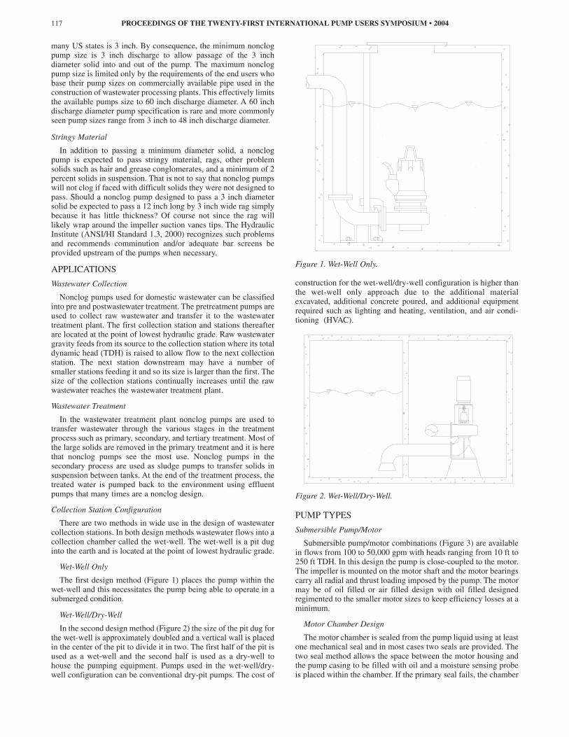
Wet-Well Only
The first design method (Figure 1) places the pump within thewet-well and this necessitates the pump being able to operate in asubmerged condition.
Wet-Well/Dry-Well
In the second design method (Figure 2) the size of the pit dug forthe wet-well is approximately doubled and a vertical wall is placedin the center of the pit to divide it in two. The first half of the pit isused as a wet-well and the second half is used as a dry-well tohouse the pumping equipment. Pumps used in the wet-well/dry-well configuration can be conventional dry-pit pumps. The cost of
Figure 1. Wet-Well Only.
construction for the wet-well/dry-well configuration is higher thanthe wet-well only approach due to the additional materialexcavated, additional concrete poured, and additional equipmentrequired such as lighting and heating, ventilation, and air condi-tioning (HVAC).
Figure 2. Wet-Well/Dry-Well.
PUMP TYPES
Submersible Pump/Motor
Submersible pump/motor combinations (Figure 3) are availablein flows from 100 to 50,000 gpm with heads ranging from 10 ft to250 ft TDH. In this design the pump is close-coupled to the motor.The impeller is mounted on the motor shaft and the motor bearingscarry all radial and thrust loading imposed by the pump. The motormay be of oil filled or air filled design with oil filled designedregimented to the smaller motor sizes to keep efficiency losses at aminimum.
Motor Chamber Design
The motor chamber is sealed from the pump liquid using at leastone mechanical seal and in most cases two seals are provided. Thetwo seal method allows the space between the motor housing andthe pump casing to be filled with oil and a moisture sensing probeis placed within the chamber. If the primary seal fails, the chamber
PROCEEDINGS OF THE TWENTY-FIRST INTERNATIONAL PUMP USERS SYMPOSIUM • 2004117

Figure 3. Wet-Well Submersible.
begins to fill with water and the moisture sensor alerts the stationoperator of a primary seal failure. The secondary seal acts toprevent the admission of oil and water into the motor housing inthe event of primary seal failure.
Power Cables
Power is supplied to the motor using cables listed to NFPA 70(National Electric Code) Section 400. The cables are designatedfor extra hard usage, employ thermoset plastic insulation and oil-resistant thermoset jackets, and are suitable for submersion inwater.
Motor Cooling
The motor is cooled through convection from the motor shell tothe fluid in the wet-well. Additional cooling may be supplied bytransferring heat from the motor to the pumped fluid using acirculated cooling system that can be supplied as either a closedloop or open loop system. In the closed loop system a clean fluidis circulated around the motor and the heat is transferred to thepumped fluid using a heat exchanger integral with the motor. Theopen loop system bleeds off a portion of the pumped fluid,circulates it around the motor, and then returns it to the pump. Overtime the open loop system may accumulate grit, grime, grease,sewage, etc., on the shell of the motor housing. This accumulationreduces the ability of the motor to transfer heat and results inincreased motor operating temperatures.
Wet-Well Use
Submersible pump/motors installed in a wet-well are typicallymounted on rails and lowered into the wet-well and accessed formaintenance via the rails. Large pump/motors can be difficult tohandle in and out of the wet-well due to their size, weight, andrigging requirements. Bosserman and Behnke (1998) havesuggested that brake horsepower (bhp) for wet-well submersiblepumps be limited to 150 bhp to keep the size of the unitsreasonable for handling. If the wet-well is rated as a hazardouslocation then the motor must be certified for use in thatenvironment.
Dry-Well Use
Submersible pump/motors can be installed in a dry-pit (Figure4) instead of, or as a replacement for, a conventional vertical
frame-mounted pump. A circulating cooling system must be usedor the motor must be derated since many pump/motor combina-tions rated for use in wet-wells cannot be used in a dry-well orcontinually operated in a wet-well with the fluid level below themotor housing without overheating the motor. If the pumped fluidis circulated around the motor, then ensure that the jacket is peri-odically cleaned or the motor is derated to account for theaccumulation of particulates/sludge on the jacket and the corre-sponding reduction in heat transfer.
Figure 4. Dry-Well Submersible.
Vertical Turbine Nonclog Pumps
Vertical turbine nonclog pumps (Figure 5) are available in flowsfrom 1500 to 70,000 gpm with heads ranging from 10 ft to 100 ftTDH/stage. Vertical turbine nonclog pumps combine the proventechnologies of vertical turbine type pumps with that of a nonclogpump design. Most of the pump uses standard vertical turbinepump (VTP) technology such as column pipe, shafting, bearings,and discharge head. It differs from standard VTP pumps by usingan overhung impeller with no bearing in the suction bell (tailbearing), a nonclog impeller, a nonclog diffuser (bowl) with two orthree vanes, and a splitter in the column and discharge elbow toprevent the accumulation of material at the intersection of theenclosing tube with the discharge head elbow. The line shaft andbowl bearing are flushed with clean water from an external source.The pump is operated submerged in the wet-well and the motor ismounted above the wet-well and is therefore protected fromflooding by the pumped fluid. The motor carries the hydraulicthrust of the pump and the motor thrust bearing must be sizedaccordingly. The entire pump must be pulled for maintenance.
Dry Pit
Conventional dry-pit nonclog pumps are available in flows from100 to 100,000� gpm with heads ranging from 10 ft to 250 ftTDH. The available design variants are horizontally-mounted,vertical frame-mounted, and vertical long-shafted.
Horizontally-Mounted
A horizontally-mounted nonclog pump (Figure 6) places thepump and driver on a common baseplate in the dry-pit. Thisconfiguration exposes both the pump and motor to flooding, placesall equipment together for ease of maintenance, requires no verticalfloor penetrations, and minimizes height requirements. However,
DESIGN CONSIDERATIONS FOR NONCLOG PUMPS 118

Figure 5. Vertical Turbine Nonclog Pump.
what would have gone up must now be laid on its side and hori-zontally-mounted units take up more square footage of floor spacethan their vertical frame-mounted cousins. The coupling placedbetween the driver and the pump can be a gear, flexible-disc,elastomeric, or spring-grid design. The use of a spacer couplingbetween the driver and pump allows the removal and maintenanceof the pump pull-out assembly without disturbing the driver. Thepump normally carries all hydraulic loading and vibration isminimal due to rigid mounting.
Figure 6. Horizontal Nonclog Pump.
Vertical Frame-Mounted
A vertical frame-mounted nonclog pump is mounted verticallyin the dry-well with the motor mounted directly to it using a motorstand. This configuration exposes both the pump and motor toflooding and places all equipment together for ease ofmaintenance. It requires less floor space than horizontally-mounted equipment but requires more vertical rise. The couplingplaced between the driver and the pump can be a gear, flexible-disc, elastomeric, or spring-grid design. The pump normallycarries all hydraulic loading.
Reed-Critical Frequency—The rise in vertical height makes thevertical frame-mounted pump susceptible to higher vibration levels
since the point of rotation for the unit center of gravity is about thebase and allows a small force to create a larger moment. Vibrationlevels on a vertical frame-mounted unit will be higher than those ofidentical units that are either horizontally-mounted or are verticallong-shafted. In addition, the direct mounting of the motor above thepump adds to system flexibility and the reed-critical frequency ofthe assembled motor/pump/foundation system can be considerablybelow that calculated for the pump or the motor alone. It is notuncommon for the assembled reed-critical frequency to be on theorder of 50 percent of that calculated for the motor alone.
Motor Stand Mounting—Mounting of the motor stand to thepump is accomplished by either mounting to the casing pressureflange or to feet cast integral with the casing.
On pumps 24 inch discharge diameter and less the motor standis usually mounted to the casing pressure flange (Figure 7). Theoverall stiffness of this mounting is low due to flexibility of thecasing wall and casing flexing due to pressure pulsations canincrease the motor vibration levels. The addition of the motor standcan limit available space to work on couplings and seals.
Figure 7. Vertical Frame Mounted (Casing Pressure Flange)Nonclog Pump.
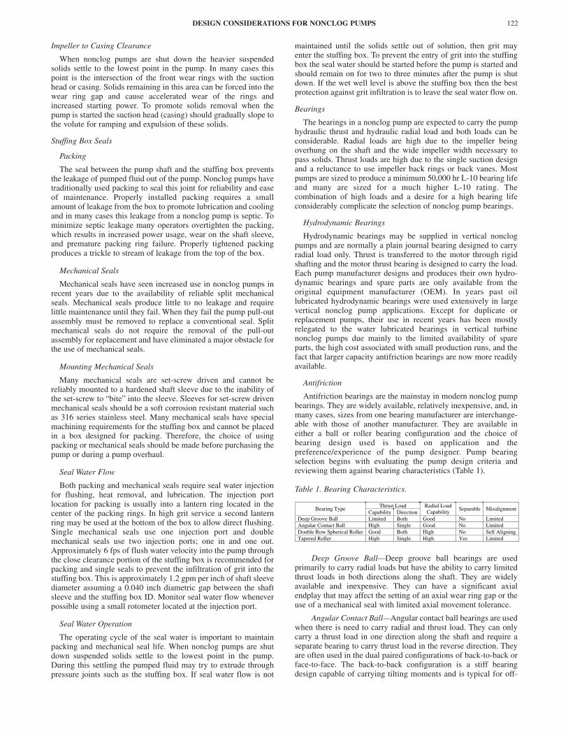
On pumps 30 inch discharge diameter and larger the motor standwill normally be mounted on feet cast integral with the casing(Figure 8). The feet should be located near the outer periphery ofthe pump casing so that the motor load is transferred directly to thefoundation where possible. This will provide high stiffness, rigidmounting, and good vibration levels. Mounting the motor stand onfeet cast integral with the casing also minimizes vibration increaseas a result of pressure fluctuations within the casing and potentiallyprovides more room to work on the coupling and seal. Theseadvantages result in increased cost for both the casing casting andthe motor stand weldment.
Vertical Long-Shafted
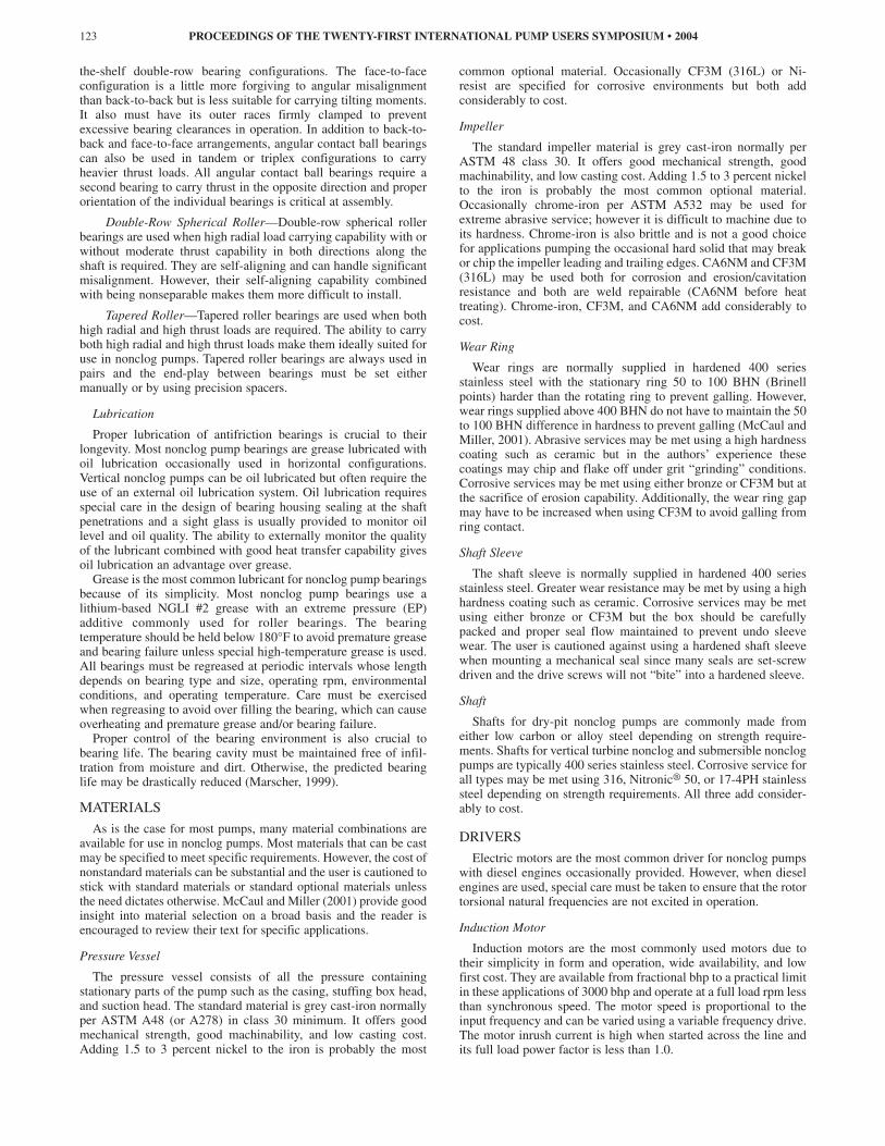
In a vertical long-shafted unit (Figure 9) the pump is mountedvertically in the dry-well and the motor is mounted on a floor(s)above. This configuration exposes the pump to flooding butprotects the motor, which is easily damaged and expensive torepair. The pump and driver are connected using intermediatedriveshaft(s) of universal-joint, flexible-disc, or solid shaftingdesign. The combined length of the intermediate driveshaft(s) isnot limited but the length of the individual sections is limited by
PROCEEDINGS OF THE TWENTY-FIRST INTERNATIONAL PUMP USERS SYMPOSIUM • 2004119
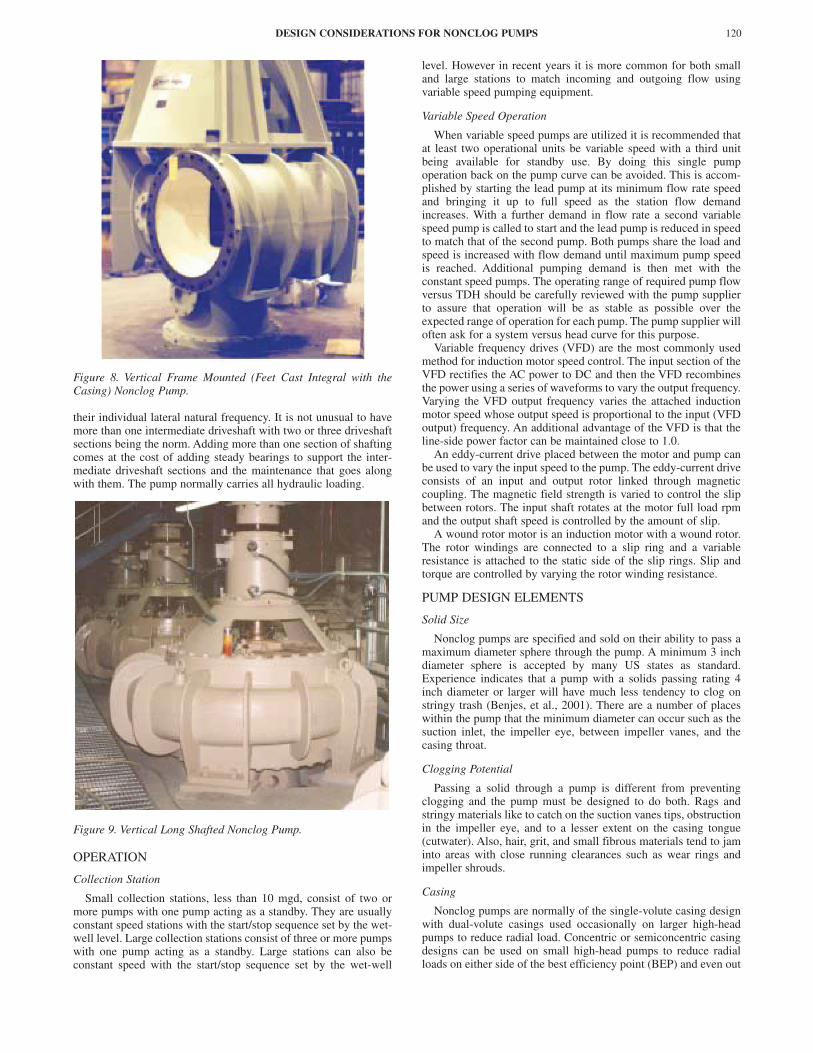
Figure 8. Vertical Frame Mounted (Feet Cast Integral with theCasing) Nonclog Pump.
their individual lateral natural frequency. It is not unusual to havemore than one intermediate driveshaft with two or three driveshaftsections being the norm. Adding more than one section of shaftingcomes at the cost of adding steady bearings to support the inter-mediate driveshaft sections and the maintenance that goes alongwith them. The pump normally carries all hydraulic loading.
Figure 9. Vertical Long Shafted Nonclog Pump.
OPERATION
Collection Station
Small collection stations, less than 10 mgd, consist of two ormore pumps with one pump acting as a standby. They are usuallyconstant speed stations with the start/stop sequence set by the wet-well level. Large collection stations consist of three or more pumpswith one pump acting as a standby. Large stations can also beconstant speed with the start/stop sequence set by the wet-well
level. However in recent years it is more common for both smalland large stations to match incoming and outgoing flow usingvariable speed pumping equipment.
Variable Speed Operation
When variable speed pumps are utilized it is recommended thatat least two operational units be variable speed with a third unitbeing available for standby use. By doing this single pumpoperation back on the pump curve can be avoided. This is accom-plished by starting the lead pump at its minimum flow rate speedand bringing it up to full speed as the station flow demandincreases. With a further demand in flow rate a second variablespeed pump is called to start and the lead pump is reduced in speedto match that of the second pump. Both pumps share the load andspeed is increased with flow demand until maximum pump speedis reached. Additional pumping demand is then met with theconstant speed pumps. The operating range of required pump flowversus TDH should be carefully reviewed with the pump supplierto assure that operation will be as stable as possible over theexpected range of operation for each pump. The pump supplier willoften ask for a system versus head curve for this purpose.
Variable frequency drives (VFD) are the most commonly usedmethod for induction motor speed control. The input section of theVFD rectifies the AC power to DC and then the VFD recombinesthe power using a series of waveforms to vary the output frequency.Varying the VFD output frequency varies the attached inductionmotor speed whose output speed is proportional to the input (VFDoutput) frequency. An additional advantage of the VFD is that theline-side power factor can be maintained close to 1.0.
An eddy-current drive placed between the motor and pump canbe used to vary the input speed to the pump. The eddy-current driveconsists of an input and output rotor linked through magneticcoupling. The magnetic field strength is varied to control the slipbetween rotors. The input shaft rotates at the motor full load rpmand the output shaft speed is controlled by the amount of slip.
A wound rotor motor is an induction motor with a wound rotor.The rotor windings are connected to a slip ring and a variableresistance is attached to the static side of the slip rings. Slip andtorque are controlled by varying the rotor winding resistance.
PUMP DESIGN ELEMENTS
Solid Size
Nonclog pumps are specified and sold on their ability to pass amaximum diameter sphere through the pump. A minimum 3 inchdiameter sphere is accepted by many US states as standard.Experience indicates that a pump with a solids passing rating 4inch diameter or larger will have much less tendency to clog onstringy trash (Benjes, et al., 2001). There are a number of placeswithin the pump that the minimum diameter can occur such as thesuction inlet, the impeller eye, between impeller vanes, and thecasing throat.
Clogging Potential
Passing a solid through a pump is different from preventingclogging and the pump must be designed to do both. Rags andstringy materials like to catch on the suction vanes tips, obstructionin the impeller eye, and to a lesser extent on the casing tongue(cutwater). Also, hair, grit, and small fibrous materials tend to jaminto areas with close running clearances such as wear rings andimpeller shrouds.
Casing
Nonclog pumps are normally of the single-volute casing designwith dual-volute casings used occasionally on larger high-headpumps to reduce radial load. Concentric or semiconcentric casingdesigns can be used on small high-head pumps to reduce radialloads on either side of the best efficiency point (BEP) and even out
DESIGN CONSIDERATIONS FOR NONCLOG PUMPS 120

radial loads across the performance curve. The use of a concentricor semiconcentric casing typically results in a reduction in pumpefficiency. All casing designs must be provided with wellrounded/blunt cutwaters to minimize clogging.
Impeller
Nonclog pump designs are available in specific speeds Ns =1500 to 5000 with most designs in the range of Ns = 2000 to 3500.Flows are available from 100 to 100,000� gpm, heads from 10 ftto 250 ft TDH, and synchronous shaft speeds from 300 to 2000rpm. Most impellers fall into the mixed flow regime and are char-acterized by a wide discharge, large eyes, and as few blades aspractical.
Number of Vanes
Minimizing the number of vanes increases the potential solidsize rating by increasing the distance between blades and reducingthe impeller eye blockage. By reducing the number of vanes theopportunity for clogging is also reduced. For example, a two vaneimpeller has two-thirds the opportunity for rags catching on thevanes as a three vane impeller per shaft revolution. In most casesreducing the number of vanes comes with cost. Minimizing thenumber of blades can affect pump performance through areduction in pump efficiency, an increase in vane loading, anincrease in the slope of the head-capacity curve, an increase inpressure pulsation, and an increase in torque pulsation. Therefore,nonclog pump impellers are designed with as few blades aspractical to meet the specified conditions-of-service withoutexcessive clogging.
Single Bladed Impeller
A single bladed impeller offers the lowest number of bladespossible for conventional nonclog centrifugal impeller design.However, it is difficult to achieve balance of the impeller inoperation since impellers are traditionally balanced dry and operatewet. When balancing dry there is no weight present for the off shaftcenter, center-of-gravity (cg) of the water mass within an operatingsingle vane impeller. If the impeller is in balance dry, it will be outof balance in operation. Some manufacturers purposefully balancetheir single vane impellers with a specific imbalance designed tocounteract the off shaft center cg of the impeller water mass.Therefore, single vane impellers should not be further recut tochange performance without correctly adjusting the imbalance orsignificant vibration can result.
Impeller and Casing Multiplicity
Most manufacturers have multiple impeller designs for casingswithin their product line. This allows the manufacturer to meetdifferent specified conditions with minimum capital investment. Inaddition, most nonclog impellers can be cut down to approximately80 percent of their full diameter to meet a specific condition-of-service. When a system is designed for both present and futureconditions-of-service the designer may be able to achieve bothconditions using a combination of techniques. The existingcondition may be met using a minimum diameter impeller and theninstalling a larger diameter impeller in the casing to meet the futureconditions. Or future conditions may be met by installing a newhigher capacity impeller in the existing casing. Motor bhp require-ments and the impeller interface with other components such as theshaft, wear rings, and suction head must be considered.
Impeller Eye
The impeller eye design is constrained by the need to keep theimpeller eye large to pass solids and at the same time keep it smallto minimize loading and wear. A large eye minimizes clogging andnet positive suction head required (NPSHR) and maximizes solidsize capability. A large eye may also increase the casing or suctionhead size and decreases the impeller diameter available to trim. A
small eye minimizes axial load and impingement velocity at theoutside diameter of the suction vane tips.
Attachment to Shaft
The attachment of the impeller to the shaft must be designed toprevent protrusions of sharp edges into the flow stream. Acontoured impeller nut with a recessed fastener(s) works well. Themounting face of the nut on the impeller should be placed toprevent sharp intersection with the suction vane tips.
Wear Ring Design
A wear ring is used to supply a renewable gap at the intersectionof the impeller with the casing. Nonclog pumps traditionally use onlyone set of wear rings located at the inlet eye to the impeller. Highhead pumps may use an additional set of back wear rings located onthe rear shroud of the impeller to reduce the high axial loads causedby the higher pressures over the imbalanced areas. All wear ringdesigns for nonclog pumps should be of a smooth surface withoutirregularities for debris in the pumped liquid to catch or lodge.
Types and Location
Front wear rings come in axial and radial wear ring configura-tion. Axial wear rings place the wearing gap on a planeperpendicular to the shaft axis and protect the nose of the impellerfrom wear. The gap is normally adjustable using shims orjackscrews located exterior to the pressure containing parts. Thisallows the axial wear ring gap to be adjusted to compensate forwear and/or to clear clogged debris from the wear ring gap. Radialwear rings place the wearing gap parallel to the shaft axis and areavailable in the two basic types of straight and L-type rings. Radialwear rings are nonadjustable and the gap is controlled either bycontrolling the component tolerances or by manually setting the gapduring installation of the pull-out assembly into the pump casing.L-type rings protect the nose of the impeller and suction head fromwear and thereby offer a slight advantage over straight radial rings.
Flush Wear Rings
Pumping fluids with high concentrations of abrasives and/orsmall fibrous materials may require using clean water to flush thewear ring gap. If supplied, flush wear rings should be designed toprovide a minimum of 6 fps of flow velocity toward the dischargefrom the wear ring gap. To achieve the desired flow the wear ringinner diameter (ID) gap will normally be tighter than that to theouter diameter (OD) gap (Figure 10).
Figure 10. Flush Wear Ring Design.
PROCEEDINGS OF THE TWENTY-FIRST INTERNATIONAL PUMP USERS SYMPOSIUM • 2004121
Impeller to Casing Clearance
When nonclog pumps are shut down the heavier suspendedsolids settle to the lowest point in the pump. In many cases thispoint is the intersection of the front wear rings with the suctionhead or casing. Solids remaining in this area can be forced into thewear ring gap and cause accelerated wear of the rings andincreased starting power. To promote solids removal when thepump is started the suction head (casing) should gradually slope tothe volute for ramping and expulsion of these solids.
Stuffing Box Seals
Packing
The seal between the pump shaft and the stuffing box preventsthe leakage of pumped fluid out of the pump. Nonclog pumps havetraditionally used packing to seal this joint for reliability and easeof maintenance. Properly installed packing requires a smallamount of leakage from the box to promote lubrication and coolingand in many cases this leakage from a nonclog pump is septic. Tominimize septic leakage many operators overtighten the packing,which results in increased power usage, wear on the shaft sleeve,and premature packing ring failure. Properly tightened packingproduces a trickle to stream of leakage from the top of the box.
Mechanical Seals
Mechanical seals have seen increased use in nonclog pumps inrecent years due to the availability of reliable split mechanicalseals. Mechanical seals produce little to no leakage and requirelittle maintenance until they fail. When they fail the pump pull-outassembly must be removed to replace a conventional seal. Splitmechanical seals do not require the removal of the pull-outassembly for replacement and have eliminated a major obstacle forthe use of mechanical seals.
Mounting Mechanical Seals
Many mechanical seals are set-screw driven and cannot bereliably mounted to a hardened shaft sleeve due to the inability ofthe set-screw to “bite” into the sleeve. Sleeves for set-screw drivenmechanical seals should be a soft corrosion resistant material suchas 316 series stainless steel. Many mechanical seals have specialmachining requirements for the stuffing box and cannot be placedin a box designed for packing. Therefore, the choice of usingpacking or mechanical seals should be made before purchasing thepump or during a pump overhaul.
Seal Water Flow
Both packing and mechanical seals require seal water injectionfor flushing, heat removal, and lubrication. The injection portlocation for packing is usually into a lantern ring located in thecenter of the packing rings. In high grit service a second lanternring may be used at the bottom of the box to allow direct flushing.Single mechanical seals use one injection port and doublemechanical seals use two injection ports; one in and one out.Approximately 6 fps of flush water velocity into the pump throughthe close clearance portion of the stuffing box is recommended forpacking and single seals to prevent the infiltration of grit into thestuffing box. This is approximately 1.2 gpm per inch of shaft sleevediameter assuming a 0.040 inch diametric gap between the shaftsleeve and the stuffing box ID. Monitor seal water flow wheneverpossible using a small rotometer located at the injection port.
Seal Water Operation
The operating cycle of the seal water is important to maintainpacking and mechanical seal life. When nonclog pumps are shutdown suspended solids settle to the lowest point in the pump.During this settling the pumped fluid may try to extrude throughpressure joints such as the stuffing box. If seal water flow is not
maintained until the solids settle out of solution, then grit mayenter the stuffing box. To prevent the entry of grit into the stuffingbox the seal water should be started before the pump is started andshould remain on for two to three minutes after the pump is shutdown. If the wet well level is above the stuffing box then the bestprotection against grit infiltration is to leave the seal water flow on.
Bearings
The bearings in a nonclog pump are expected to carry the pumphydraulic thrust and hydraulic radial load and both loads can beconsiderable. Radial loads are high due to the impeller beingoverhung on the shaft and the wide impeller width necessary topass solids. Thrust loads are high due to the single suction designand a reluctance to use impeller back rings or back vanes. Mostpumps are sized to produce a minimum 50,000 hr L-10 bearing lifeand many are sized for a much higher L-10 rating. Thecombination of high loads and a desire for a high bearing lifeconsiderably complicate the selection of nonclog pump bearings.
Hydrodynamic Bearings
Hydrodynamic bearings may be supplied in vertical nonclogpumps and are normally a plain journal bearing designed to carryradial load only. Thrust is transferred to the motor through rigidshafting and the motor thrust bearing is designed to carry the load.Each pump manufacturer designs and produces their own hydro-dynamic bearings and spare parts are only available from theoriginal equipment manufacturer (OEM). In years past oillubricated hydrodynamic bearings were used extensively in largevertical nonclog pump applications. Except for duplicate orreplacement pumps, their use in recent years has been mostlyrelegated to the water lubricated bearings in vertical turbinenonclog pumps due mainly to the limited availability of spareparts, the high cost associated with small production runs, and thefact that larger capacity antifriction bearings are now more readilyavailable.
Antifriction
Antifriction bearings are the mainstay in modern nonclog pumpbearings. They are widely available, relatively inexpensive, and, inmany cases, sizes from one bearing manufacturer are interchange-able with those of another manufacturer. They are available ineither a ball or roller bearing configuration and the choice ofbearing design used is based on application and thepreference/experience of the pump designer. Pump bearingselection begins with evaluating the pump design criteria andreviewing them against bearing characteristics (Table 1).
Table 1. Bearing Characteristics.
Deep Groove Ball—Deep groove ball bearings are usedprimarily to carry radial loads but have the ability to carry limitedthrust loads in both directions along the shaft. They are widelyavailable and inexpensive. They can have a significant axialendplay that may affect the setting of an axial wear ring gap or theuse of a mechanical seal with limited axial movement tolerance.
Angular Contact Ball—Angular contact ball bearings are usedwhen there is need to carry radial and thrust load. They can onlycarry a thrust load in one direction along the shaft and require aseparate bearing to carry thrust load in the reverse direction. Theyare often used in the dual paired configurations of back-to-back orface-to-face. The back-to-back configuration is a stiff bearingdesign capable of carrying tilting moments and is typical for off-
DESIGN CONSIDERATIONS FOR NONCLOG PUMPS 122
Thrust Load Bearing Type
Capability Direction Radial Load Capability
Separable Misalignment
Deep Groove Ball Limited Both Good No Limited Angular Contact Ball High Single Good No Limited Double Row Spherical Roller Good Both High No Self Aligning Tapered Roller High Single High Yes Limited
the-shelf double-row bearing configurations. The face-to-faceconfiguration is a little more forgiving to angular misalignmentthan back-to-back but is less suitable for carrying tilting moments.It also must have its outer races firmly clamped to preventexcessive bearing clearances in operation. In addition to back-to-back and face-to-face arrangements, angular contact ball bearingscan also be used in tandem or triplex configurations to carryheavier thrust loads. All angular contact ball bearings require asecond bearing to carry thrust in the opposite direction and properorientation of the individual bearings is critical at assembly.
Double-Row Spherical Roller—Double-row spherical rollerbearings are used when high radial load carrying capability with orwithout moderate thrust capability in both directions along theshaft is required. They are self-aligning and can handle significantmisalignment. However, their self-aligning capability combinedwith being nonseparable makes them more difficult to install.
Tapered Roller—Tapered roller bearings are used when bothhigh radial and high thrust loads are required. The ability to carryboth high radial and high thrust loads make them ideally suited foruse in nonclog pumps. Tapered roller bearings are always used inpairs and the end-play between bearings must be set eithermanually or by using precision spacers.
Lubrication
Proper lubrication of antifriction bearings is crucial to theirlongevity. Most nonclog pump bearings are grease lubricated withoil lubrication occasionally used in horizontal configurations.Vertical nonclog pumps can be oil lubricated but often require theuse of an external oil lubrication system. Oil lubrication requiresspecial care in the design of bearing housing sealing at the shaftpenetrations and a sight glass is usually provided to monitor oillevel and oil quality. The ability to externally monitor the qualityof the lubricant combined with good heat transfer capability givesoil lubrication an advantage over grease.
Grease is the most common lubricant for nonclog pump bearingsbecause of its simplicity. Most nonclog pump bearings use alithium-based NGLI #2 grease with an extreme pressure (EP)additive commonly used for roller bearings. The bearingtemperature should be held below 180°F to avoid premature greaseand bearing failure unless special high-temperature grease is used.All bearings must be regreased at periodic intervals whose lengthdepends on bearing type and size, operating rpm, environmentalconditions, and operating temperature. Care must be exercisedwhen regreasing to avoid over filling the bearing, which can causeoverheating and premature grease and/or bearing failure.
Proper control of the bearing environment is also crucial tobearing life. The bearing cavity must be maintained free of infil-tration from moisture and dirt. Otherwise, the predicted bearinglife may be drastically reduced (Marscher, 1999).
MATERIALS
As is the case for most pumps, many material combinations areavailable for use in nonclog pumps. Most materials that can be castmay be specified to meet specific requirements. However, the cost ofnonstandard materials can be substantial and the user is cautioned tostick with standard materials or standard optional materials unlessthe need dictates otherwise. McCaul and Miller (2001) provide goodinsight into material selection on a broad basis and the reader isencouraged to review their text for specific applications.
Pressure Vessel
The pressure vessel consists of all the pressure containingstationary parts of the pump such as the casing, stuffing box head,and suction head. The standard material is grey cast-iron normallyper ASTM A48 (or A278) in class 30 minimum. It offers goodmechanical strength, good machinability, and low casting cost.Adding 1.5 to 3 percent nickel to the iron is probably the most
common optional material. Occasionally CF3M (316L) or Ni-resist are specified for corrosive environments but both addconsiderably to cost.
Impeller
The standard impeller material is grey cast-iron normally perASTM 48 class 30. It offers good mechanical strength, goodmachinability, and low casting cost. Adding 1.5 to 3 percent nickelto the iron is probably the most common optional material.Occasionally chrome-iron per ASTM A532 may be used forextreme abrasive service; however it is difficult to machine due toits hardness. Chrome-iron is also brittle and is not a good choicefor applications pumping the occasional hard solid that may breakor chip the impeller leading and trailing edges. CA6NM and CF3M(316L) may be used both for corrosion and erosion/cavitationresistance and both are weld repairable (CA6NM before heattreating). Chrome-iron, CF3M, and CA6NM add considerably tocost.
Wear Ring
Wear rings are normally supplied in hardened 400 seriesstainless steel with the stationary ring 50 to 100 BHN (Brinellpoints) harder than the rotating ring to prevent galling. However,wear rings supplied above 400 BHN do not have to maintain the 50to 100 BHN difference in hardness to prevent galling (McCaul andMiller, 2001). Abrasive services may be met using a high hardnesscoating such as ceramic but in the authors’ experience thesecoatings may chip and flake off under grit “grinding” conditions.Corrosive services may be met using either bronze or CF3M but atthe sacrifice of erosion capability. Additionally, the wear ring gapmay have to be increased when using CF3M to avoid galling fromring contact.
Shaft Sleeve
The shaft sleeve is normally supplied in hardened 400 seriesstainless steel. Greater wear resistance may be met by using a highhardness coating such as ceramic. Corrosive services may be metusing either bronze or CF3M but the box should be carefullypacked and proper seal flow maintained to prevent undo sleevewear. The user is cautioned against using a hardened shaft sleevewhen mounting a mechanical seal since many seals are set-screwdriven and the drive screws will not “bite” into a hardened sleeve.
Shaft
Shafts for dry-pit nonclog pumps are commonly made fromeither low carbon or alloy steel depending on strength require-ments. Shafts for vertical turbine nonclog and submersible nonclogpumps are typically 400 series stainless steel. Corrosive service forall types may be met using 316, Nitronic® 50, or 17-4PH stainlesssteel depending on strength requirements. All three add consider-ably to cost.
DRIVERS
Electric motors are the most common driver for nonclog pumpswith diesel engines occasionally provided. However, when dieselengines are used, special care must be taken to ensure that the rotortorsional natural frequencies are not excited in operation.
Induction Motor
Induction motors are the most commonly used motors due totheir simplicity in form and operation, wide availability, and lowfirst cost. They are available from fractional bhp to a practical limitin these applications of 3000 bhp and operate at a full load rpm lessthan synchronous speed. The motor speed is proportional to theinput frequency and can be varied using a variable frequency drive.The motor inrush current is high when started across the line andits full load power factor is less than 1.0.
PROCEEDINGS OF THE TWENTY-FIRST INTERNATIONAL PUMP USERS SYMPOSIUM • 2004123

Synchronous Motor
Synchronous motors operate at a full load operating rpm equalto synchronous speed. They are started as a conventional inductionmotor and therefore have the same high inrush current when startedacross the line. When the motor is close to full load speed thewindings are energized and the motor pulls into synchronousspeed. Synchronous motors are used for large constant speed loadapplications in a range of 500 to 3000 bhp. Synchronous motorsmay be more expensive than induction motors but they operate ata power factor of 1.0 or greater and with proper sizing can signifi-cantly reduce the power cost for the entire plant. They areparticularly advantageous in slow speed applications whereinduction motors typically have significantly lower power factors.Synchronous motors can be operated variable speed using a loadcommutated inverter (LCI) drive.
VIBRATION
Acceptance Criteria
Nonclog pump specifications typically reference ANSI/HIStandard 9.6.4 (2000) to specify acceptable vibration limits.ANSI/HI Standard 9.6.4 (2000) bases the allowable vibration levelon the bhp produced during measurement and whether the pumpis horizontally or vertically oriented. All measurements areunfiltered, root-mean-square (RMS) averaged, and vibration at themotor is not part of the specification. Allowable vibration levelsmeasured at the pump bearing housing range from 0.22 to 0.34 ipszero-to-peak RMS unfiltered. These are reasonable vibration levelsfor the pump but vibration levels at the motor, which is normally amore expensive machine than the pump, have to be specified froma different source such as ISO 10816.
Lilly and Marscher (1998) have suggested a conservativeapproach to vibration acceptance testing based on vibration meas-urements not exceeding any of the following three vibration levels atany frequency: 2.0 mils peak-to-peak, 0.25 ips zero-to-peak, and 1.0 g peak. Applying the criteria to nonclog pumps seems acceptableexcept in the frequency range covered by vane pass frequency wherethe 2.0 mils peak-to-peak criterion may fail large slow speed pumpslikely to give good service life. Applying a criterion of 0.25 ips zero-to-peak at vane pass frequency is more suitable.
Lilly and Marscher (1998) also recognize that the vibration atthe top of a motor mounted to a tall vertical pump will be signifi-cantly higher than it is at the pump bearing frame due to rotationof the unit about the pump anchorage. Increasing the acceptancecriteria based on a ratio of heights above the pump anchorageseems reasonable.
Vibration Diagnosis
Much has been written about the diagnosis of machineryvibration based on measurements of frequency, phase, andamplitude and it does not need repeating here. The reader isencouraged to review Table 22-1 of Lilly and Marscher (1998) foran excellent review of vibration troubleshooting tips targeted atpump vibration diagnosis.
Problem Sources
The three excitation frequencies of 1�, 2�, and vane pass canalways be counted on to show up in the vibration spectra forproperly designed nonclog pumps. 1� shows up due to residualimbalance and coupling misalignment. 2� shows up due tocoupling misalignment and as the universal-joint coupling’sexcitation frequency. Vane pass shows up as a strong excitation dueto the low number of vanes used. For example, a two vane 200 bhpmachine produces 100 bhp from each blade and the blade passesthe cutwater twice in a revolution. Pressure and torque pulsationsare the result.
Nonclog pump impellers are run at full load speeds ranging from360 rpm to 2000 rpm and the number of impeller vanes varies from
a minimum of one at 1800 rpm to a maximum of five or more inthe larger low speed pumps. This can result in vane passfrequencies ranging from below 10 hz to over 60 hz. Unfortunatelythe majority of structural natural frequencies for vertical units willfall within this range. Combining the vane pass frequencyexcitation with 1� and 2� excitation produces a range of excitationsources that are difficult to avoid. The possibility of exciting astructural resonant frequency is very high, especially if the unit isvariable speed.
UPFRONT VIBRATION ANALYSIS
An accurate upfront vibration analysis provides the best chanceof not encountering vibration problems in the field that are in mostcases difficult to correct and in all cases expensive to correct.Upfront vibration analysis consists of accurately predicting thenatural frequencies and placing their occurrence at frequenciesleast likely to harm the equipment. Upfront analysis should only beperformed by personnel experienced with what it takes to performan accurate analysis. It does not make sense to spend money on ananalysis that is not consistent with the field vibration measuredsimply because the analyst was not familiar with currenttechniques and/or methods. The following can be consideredminimum analysis requirements:
• A structural natural frequency analysis should include the motor,pump, foundation, attached piping, and entrained water.
• A rotor lateral natural frequency analysis should include shafts,bearing stiffness, couplings, masses, inertias, and entrained water.
• A rotor torsional natural frequency analysis should includeshafts, couplings, masses, and inertias for both the motor andpump.
Vertical Frame-Mounted
Vertical frame-mounted nonclog pumps have the largestpotential for exciting a structural resonance. A structural lateralnatural frequency analysis of the motor/pump assembly should beperformed on all new designs that do not have a history of beingsold and on all variable speed units larger than 100 bhp. The needfor upfront vibration analysis work on constant speed units largerthan 100 bhp should be determined by using the motor reed-criticalfrequency as a guide. Assume the mounted motor reed-criticalfrequency will be on the order of 50 percent of that calculated bythe motor vendor and compare it to the excitation frequencies.Upfront analysis work on units less than 100 bhp may be moreexpensive than field fixes and therefore may not make economicsense for all applications. A torsional natural frequency analysisshould be performed for all units.
Vertical Long-Shafted
Constant speed vertical long-shafted nonclog pumps have littlepossibility of exciting a structural natural frequency unless thepump or the motor is mounted to a nonrigid structure, which isquite often the case for the motors of these units. A structurallateral natural frequency analysis of the motor and/or the pumpshould be performed on all variable speed units larger than 100bhp, and on all equipment not mounted to a rigid structure. Thetorsional natural frequencies of the entire drive train and the lateralnatural-frequencies of the intermediate driveshaft should becalculated for all units.
Vertical Turbine Nonclog
Vertical turbine nonclog pumps have a large potential forexciting a structural resonance. A structural lateral naturalfrequency analysis of the motor/pump/column assembly should beperformed on all units regardless of history. A torsional and lateralnatural frequency analysis of the entire drive-train should beperformed for all units.
DESIGN CONSIDERATIONS FOR NONCLOG PUMPS 124

Horizontal Units
Horizontal nonclog pumps have little possibility of exciting ashafting lateral natural frequency or a structural natural frequencyunless they are not directly mounted to a substantial foundation ora variable speed drive is used. The only upfront analysis worktypically required is to calculate the torsional natural frequency ofthe entire drive-train.
TYPICAL PROBLEMS AND SOLUTIONS
Table A-1 (please refer to APPENDIX A) lists symptoms,diagnoses, and solutions for typical problems seen with nonclogpumps excepting vibration, which is covered under the sectionentitled Vibration Diagnosis.
EQUIPMENT UPGRADES
Introduction
Water treatment plant personnel and their consultants face a longlist of issues exacerbated by ever tightening environmentalregulations. Just to mention a few:
• Plant capacity mismatched to base and peak loads
• Obsolete equipment
• Restricted funding
• Cannot shut the plant down to work on subsystems
• Unreliable equipment
How then can plant capacity be modified, and obsoleteequipment modernized and upgraded with minimum expendituresall while operating the plant? In particular, how can nonclog pumpsbe upgraded? The answer is to specify the purchase and installationof modern pull-out-assemblies (POA) and upgrades one pump at atime. The POA consists of the pump bearing frame, shaft, impellerwith wear rings, and the stuffing box. Okay, sounds easy but:
• Our pumps are 70 years old! Surely they need to be replaced.
• We have built the plant around the pumps so now we would haveto demolish walls, conduits, ventilation ducts, and floors just togain access.
• We need to increase pump flow by 50 percent, so we must neednew pumps.
• All of the patterns for my pumps have been destroyed. It willcost too much to make a POA.
• Our pumps were manufactured by “XYZ Pump Co.” who nolonger is in the business.
• We need VFDs but who would handle the torsional and lateralcritical frequency issues?
Answers to these questions and more:
How Old is too Old?
The age of a pump has little bearing on the application of a POAto upgrade it. In fact, the older volute designs are, in many cases, atrue involute spiral not a modern shape that has been squeezed tominimize cost at the expense of pump efficiency. This means thatthe distance from the centerline of the suction to the centerline ofthe discharge is greater in older pumps than in their modern coun-terparts. This fact adds cost to complete pump replacement becausethe piping must be demolished and reconstructed to adapt themodern dimensions.
Recent experience suggests that large sewage pump casingshave very long service lives. In fact, the older units exhibit muchless wear, as a percentage of original wall thickness, than modernpumps. There are two reasons for this observation. Competitionhas forced pump designers to increase flow velocity while reducingcasting wall thickness. Simply stated, high fluid velocity (with
suspended abrasive solids) combined with thin casing sections,means shorter casing life. Wear in sewage pumps is generallylimited to rings, bearings, and impellers.
Fitness-for-Use Inspection
When a pump upgrade is being considered, a fitness-for-useinspection should be conducted (Figure 11). These inspectionsshould include an ultrasonic thickness test of the casing at knownwear locations along with a visual check of suspect areas and thevolute cutwater. In unusual cases, some wall thickness reduction isobserved but the pump OEM can calculate the “retiring” thicknessin a specific example that usually results in many additional yearsof pump life. Casing cutwater wear can be repaired by fieldmachining the case to accept a fabricated cutwater extension. Insituations where casing locating fits have worn the mating partsmay be assembled, adjusted for internal alignment, then taperdoweled into position.
Figure 11. Fitness for Use Inspection.
Changing Performance
Treatment plants that are faced with the need to increase orreduce pump flow can also use the POA technique on existingcasings. Volute pumps in the specific speed range normallyassociated with sewage pumps are surprisingly insensitive tovolute to impeller match. To appreciate this, review a manufac-turer’s catalog performance curves and you should find that aparticular pump model (size) shows several different performancecurves for different impeller designs in the same casing. Forexample, one manufacturer catalogs nine different impellerhydraulic designs for one volute design! Using a POA with a newor different impeller than the original may allow the performanceto be changed and the equipment life to be extended.
POA or New Pumps?
Once the decision to upgrade a pump or set of pumps is made,an assessment of the site conditions must be made.
In many cases pumps in the lower levels of the plant cannot beremoved without total demolition of a building. In a largewastewater treatment plant in New Jersey, the five 42 inchdischarge primary effluent pumps are installed in a long straightline, up against the wet well. There is access to the pumps on theopposite side of the room but the walkway is not as wide as thepump casing. Since the access hatch is located at one end of theline of pumps, there is no way to replace the last casing withoutremoving the first four pumps (Figure 12). Of course, that wouldmean shutting down the entire plant for months—not an option.On the other hand, a POA is typically less than 30 percent of thewidth of an entire pump so it may be transported through tightspaces.
PROCEEDINGS OF THE TWENTY-FIRST INTERNATIONAL PUMP USERS SYMPOSIUM • 2004125
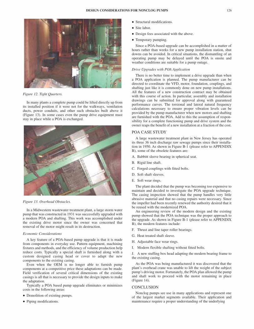
Figure 12. Tight Quarters.
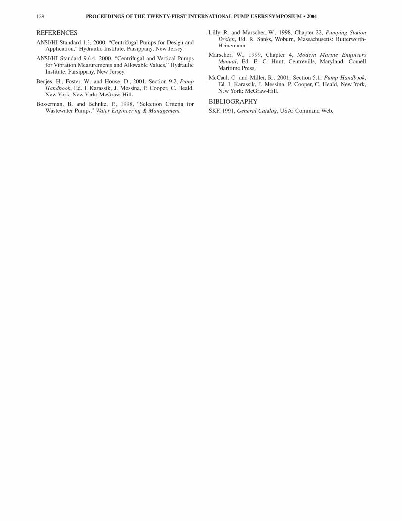
In many plants a complete pump could be lifted directly up fromits installed position if it were not for the walkways, ventilationducts, power conduits, and other such obstacles built above it(Figure 13). In some cases even the pump drive equipment muststay in place while a POA is exchanged.
Figure 13. Overhead Obstacles.
In a Midwestern wastewater treatment plant, a large storm waterpump that was constructed in 1931 was successfully upgraded witha modern POA and shafting. This work was accomplished underthe existing drive motor since the owner was concerned thatremoval of the motor might result in its destruction.
Economic Considerations
A key feature of a POA-based pump upgrade is that it is madefrom components in everyday use. Pattern equipment, machiningfixtures and methods, and the efficiency of volume production helpreduce costs. Typically a special shaft is furnished along with acustom designed casing head or cover to adapt the newcomponents to the existing casing.
Even when the OEM is no longer able to furnish pumpcomponents at a competitive price these adaptations can be made.Field verification of several critical dimensions of the existingcasings is all that is necessary to provide the design inputs to makethe adaptation.
Typically a POA based pump upgrade eliminates or minimizescosts in the following areas:
• Demolition of existing pumps.
• Piping modifications.
• Structural modifications.
• Site labor.
• Design fees associated with the above.
• Temporary pumping.
Since a POA-based upgrade can be accomplished in a matter ofhours rather than weeks for a new pump installation station, shutdowns can be avoided. In critical situations, the dismantling of anoperating pump may be delayed until the POA is onsite andweather conditions are suitable for a pump outage.
Drive Upgrades with POA Application
There is no better time to implement a drive upgrade than whena POA application is planned. The pump manufacturer can bedirected to coordinate the VFD, motor, foundation, couplings, andshafting just like it is commonly done on new pump installations.All the features of a new construction contract may be obtainedwith this course of action. In particular, assembly and installationdrawings can be submitted for approval along with guaranteedperformance curves. The torsional and lateral natural frequencycalculations necessary to ensure proper vibration levels can beprovided by the pump manufacturer when new motors and shaftingare furnished with the POA. Add to this the assumption of respon-sibility for a complete functioning pump and drive system and theowner reaps the benefit of a new installation at a fraction of the cost.
POA CASE STUDY
A large wastewater treatment plant in New Jersey has operatedits three 36 inch discharge raw sewage pumps since their installa-tion in 1950. As shown in Figure B-1 (please refer to APPENDIXB), some of the obsolete features are:
A. Babbitt sleeve bearing in spherical seat.
B. Rigid line shaft.
C. Forged couplings with fitted bolts.
D. Soft shaft sleeves.
E. Soft wear rings.
The plant decided that the pump was becoming too expensive tomaintain and decided to investigate the POA upgrade technique.The casing inspection showed that the pump handles very littleabrasive material and that no casing repairs were necessary. Sincethe impeller had been recently renewed the authority desired that itbe reused with the modernized POA.
An engineering review of the modern design and the existingpump showed that the POA technique was the proper approach tothe upgrade. As shown in Figure B-1 (please refer to APPENDIXB), the modern features include:
F. Thrust and line taper roller bearings.
G. Heat treated shaft sleeve.
H. Adjustable face wear rings.
I. Modern flexible shafting without fitted bolts.
J. A new stuffing box head adapting the modern bearing frame tothe existing casing.
As the POA was being manufactured it was discovered that theplant’s overhead crane was unable to lift the weight of the subjectpump’s driving motor. Fortunately, the POA plan allowed the pumpand shaft work to proceed with the motor remaining in place(Figure 14).
CONCLUSIONNonclog pumps see use in many applications and represent one
of the largest market segments available. Their application andmaintenance require a proper understanding of the underlying
DESIGN CONSIDERATIONS FOR NONCLOG PUMPS 126

Figure 14. New POA in Place.
design issues associated with their use. Hopefully the reader is nowcognizant of these design issues and will be able to apply them tothe underappreciated, inglorious workhorse of our domesticwastewater system. Without them we would be up to our ears in,well, let’s say alligators.
NOMENCLATURE
ANSI = American National Standards InstituteBEP = Best efficiency point. The point on
the pump curve corresponding topeak pump efficiency.
BHN = Brinell hardness numbercg = Center of gravityClose-coupled = Pump with impeller mounted on the
motor shaft.COS = Condition of service. The operating
point on the pump curve representedby flow, head, and rpm.
Dry-well = A below ground pit in whichpumping equipment is mounted in anormally dry environment. Used inconjunction with a wet-well.
HI = Hydraulic InstituteOverhung impeller = Impeller located outboard of the
bearings.POA = Pull-out assembly. Pump assembly
consisting of the pump rotatingcomponents and the stationarycomponents used for their mounting,i.e., shaft, bearings, shaft sleeve,impeller, stuffing box head, bearingframe, bearing frame covers, etc.
Rotating assembly = Pump assembly consisting of thepump rotating components, i.e., shaft,bearings, shaft sleeve, impeller.
Specific speed = A dimensionless number repre-senting the hydraulic design type ofthe pump. Simplistically, a lowspecific speed represents low flowand high head and a high specificspeed represents high flow and lowhead.
System versus head curve = A curve(s) of system resistance(TDH) versus flow. Where thesystem versus head curve crosses thepump curve is the point of pumpoperation. The system resistanceconsists of piping losses, form losses(elbows, valves, etc.), and static head(height of water above or belowpump)
TDH = Total dynamic headVFD = Variable frequency driveVTP = Vertical turbine pumpWet-well = A below ground pit with or without
pumping equipment used to collectpumpage prior to processing.
PROCEEDINGS OF THE TWENTY-FIRST INTERNATIONAL PUMP USERS SYMPOSIUM • 2004127

APPENDIX A
Table A-1. Typical Problems and Solutions.
APPENDIX B
Figure B-1. Case Study New/Existing Pump Drawing.
DESIGN CONSIDERATIONS FOR NONCLOG PUMPS 128
Problem Symptom Diagnosis Solution Ring binding Pump stalls
Pump won’t start Rotor will not turn by hand No blockage in impeller Rotor turns free after clearing rings.
Fill all ring retaining screw heads with Devcon Increase ring gap Implement ring gap flushing Increase driver torque
Impeller Eye clogging
Reduction in flow. Increased vibration and/or noise
Remove hand-hole cover and inspect impeller eye. Remove any discontinuities in impeller eye and impeller retaining screw. . Change operating sequence. Operating the pump near shutoff for a short period of time to induce recirculation and clear the eye. Increase closing time of discharge check valve to allow back flow through the pump which will clear the eye at shut down.
Abrasive wear Erosion on pressure side of vane and casing cutwater
Components look like they have been scoured Coat repairable components with Devcon in areas of wear Replace with a more durable material
Low NSPHA Continuous rock tumbling noise Less TDH than expected Less Power draw than expected
Review of NPSHA vs. NPSHR shows pump has insufficient NPSHA Closing discharge valve reduces noise Increasing wet well level reduces noise. For severe lack of NPSHA, inspection of impeller shows cavitation damage on non-pressure side of vane.
Increase the wet well level Restrict single pump operation to portions of pump curve where NPSHR are met. Use new material for impeller to allow operation if TDH can be met Use an impeller with lower NPSHR
Operation in Recirculation
Discontinuous rock tumbling noise that comes and goes.
Review of NPSHA vs. NPSHR show pump has sufficient NPSHA Opening discharge valve reduces noise (suction recirculation) For severe recirculation, inspection of impeller shows cavitation like damage on pressure side of vane.
New material for impeller to allow operation Use an impeller with different recirculation characteristics
Bearings Overheat
Bearing frame hot with temperature above 160oF
Grease is black/burnt Grease is liquefied and pours out frame when grease plugs are removed Grease has impurities Check bearing rollers and cages for wear
Repack bearings and do not over grease Replace bearings Remove grease plugs after re-greasing and run pump until excess grease is purged to ensure bearings are not over greased.
Short Packing Life
Packing replaced frequently Packing is burnt Shaft sleeve is damaged
Repack box and replace sleeve Tighten packing gland to provide trickle of water from stuffing box. Ensure that 1.2 GPM of flush water is provided to each inch of shaft sleeve diameter
Power Consumption High
Power use exceeds that shown on the pump curve
Check power meter calibration and power calculation Check TDH and flow against curve Check for free turning rotor Check for tight packing Check for bound wear rings Check for bad bearings
Replace/or repair components
REFERENCES
ANSI/HI Standard 1.3, 2000, “Centrifugal Pumps for Design andApplication,” Hydraulic Institute, Parsippany, New Jersey.
ANSI/HI Standard 9.6.4, 2000, “Centrifugal and Vertical Pumpsfor Vibration Measurements and Allowable Values,” HydraulicInstitute, Parsippany, New Jersey.
Benjes, H., Foster, W., and House, D., 2001, Section 9.2, PumpHandbook, Ed. I. Karassik, J. Messina, P. Cooper, C. Heald,New York, New York: McGraw-Hill.
Bosserman, B. and Behnke, P., 1998, “Selection Criteria forWastewater Pumps,” Water Engineering & Management.
Lilly, R. and Marscher, W., 1998, Chapter 22, Pumping StationDesign, Ed. R. Sanks, Woburn, Massachusetts: Butterworth-Heinemann.
Marscher, W., 1999, Chapter 4, Modern Marine EngineersManual, Ed. E. C. Hunt, Centreville, Maryland: CornellMaritime Press.
McCaul, C. and Miller, R., 2001, Section 5.1, Pump Handbook,Ed. I. Karassik, J. Messina, P. Cooper, C. Heald, New York,New York: McGraw-Hill.
BIBLIOGRAPHYSKF, 1991, General Catalog, USA: Command Web.
PROCEEDINGS OF THE TWENTY-FIRST INTERNATIONAL PUMP USERS SYMPOSIUM • 2004129