design considerations for a minimally invasive high .... as a result several prototypes have be...
TRANSCRIPT
Abstract—Design aspects of a minimally invasive high-
throughput automation system for radiation biodosimetry are
reported. The system, currently under development, relies on
robotic devices and advanced high-speed automated image
acquisition to perform mass triage following a radiological
event. A design concept of the automation system is proposed
based on the use of an input stage, a centrifuge module, a cell
harvesting system, a liquid handling module, an imaging system
and a service robot. The biological assays are described along
with an analysis of the throughput requirements. The special
requirements imposed by bioassay automation, system
throughput and minimal invasiveness lead to the design of a
custom-made multipurpose gripper and a cell harvesting
module. Results on the embodiment design of these modules are
provided. A prototype of the automation system is described.
I. INTRODUCTION
OLLOWING a radiological event there will be a need
for mass triage requiring analysis of tens to hundreds of
thousands of samples. An example of this is the incident at
Goiânia, Brazil [1] in 1987. In the first few days after the
incident became known, about 130,000 people, out of the 1.3
million inhabitants of Goiânia arrived at screening locations
and were monitored for radiation exposure. Only those
showing both internal and external contamination were
examined using biodosimetric techniques as existing systems
for performing biodosimetric assays can handle at most a few
hundred samples per machine.
The development of automated, high-throughput systems
for biodosimetry has been declared top priority by the office
of science and technology policy and the homeland security
council [2].
During the last decade many engineers and scientists have
teamed-up in the quest for designing automated systems for
medical applications featuring higher and higher
This publication was supported by grant number U19 AI067773, the
Center for High-Throughput Minimally Invasive Radiation Biodosimetry,
from the National Institutes of Health / National Institute of Allergy and
Infectious Diseases. ∗ A. Salerno, J. Zhang, A. Bhatla, N. Simaan and Y. L. Yao are with the
Department of Mechanical Engineering, Columbia University, New York,
NY 10027 (as2948|jz2181|ab2575|ns2236|[email protected]) # O. V. Lyulko, G. Garty, G. Randers-Pehrson and D. J. Brenner are with
the Radiological Research Accelerator Facility, Columbia University,
Irvington, NY 10533 (ovl1|gyg2101|gr6|[email protected]) † J. Nie and A. Dutta are with the Center for Radiological Research,
Columbia University, New York, NY 10032
(jn2244|[email protected])
throughputs. As a result several prototypes have been
designed. Meldrum et al. have recently demonstrated a
capillary-based fluid handling system, the ACAPELLA-5K
(A5K), capable of processing genomic and chemical samples
at a throughput of 5,000 preparations/8 hours [3]. Kachel et
al. designed a custom-made automated system capable of
isolating DNA plasmids at a rate of 1,600 plasmids/12 hours
[4]. Prasanna et al. reported on the automation of cytogenetic
biodosimetry featuring a throughput of 500 samples/week
[5]. Soldatova et al. have commissioned a new robotic
system for investigations of gene function in S. cerevisiae
investigation capable of initiating more than 1,000
experiments a day [6].
Several attempts have already been made to automate
biodosimetric assays; however efforts were directed toward
automating the imaging system rather than the biological
processing itself. A rare exception to this is the work of [7]
who attempted to automate the extraction of chromosomes
from lymphocytes. The system throughput was, however
lower than that of a skilled lab technician. Even so,
throughputs are rather low, with each sample requiring
several minutes or more for imaging alone, resulting in very
low throughputs of a few tens to hundreds of samples per
day.
This work deals with the design of a minimally invasive
high-throughput automation system for radiation
biodosimetry. The goal of this paper is twofold. First, an
overview of the automation process, excluding the imaging
system, is presented within the general context of the clinical
requirements of the biodosimetry workstation. Second, a
flexible automation system is presented with the relevant
design considerations allowing the processing of 30,000
samples a day. This system is capable of process two distinct
biological assays.
The paper is divided in six sections. In Section II an
overview of the system is provided. A design concept of the
automation system is proposed along with a description of
the biological assays. Design and throughput requirements
are then discussed. Section III analyzes the design challenges
faced in achieving an embodiment of a multipurpose gripper
while Section IV provides the reader with a detailed
mechanical design of the cell-harvesting module. Finally,
section V outlines the prototype.
II. SYSTEM OVERVIEW
The proposed automation system consists of several
Design Considerations for a Minimally Invasive High-Throughput
Automation System for Radiation Biodosimetry
A. Salerno*, J. Zhang
*, A. Bhatla
∗, O. V. Lyulko
#, J. Nie
†, A. Dutta
†, G. Garty
#,
N. Simaan*, G. Randers-Pehrson
#, Y. L. Yao
* and D. J. Brenner
#
F
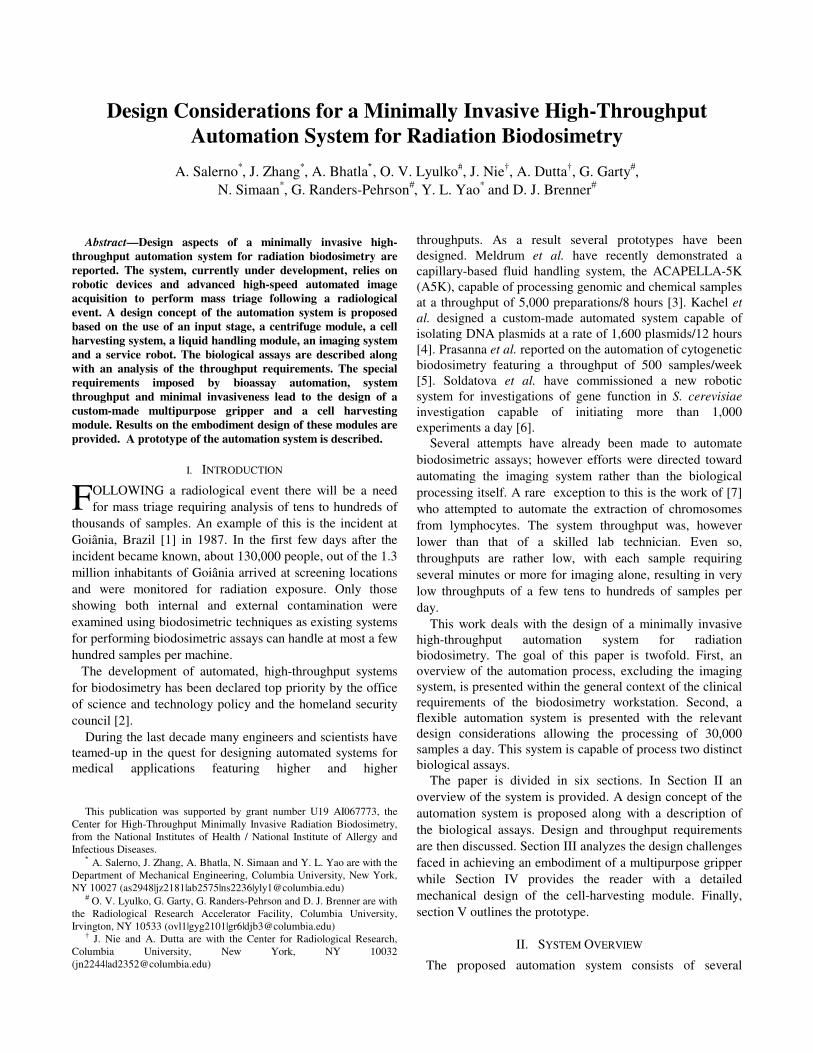
modules: input stage, centrifugation, cell-harvesting, liquid
handling, incubation and a high-speed, dedicated image
acquisition system. Excluding the latter, an overview of the
system is reported in Fig. 1.
Fig. 1. Design concept of the automation system
The input stage is a FIFO stack for interfacing the human
user and the automation system. The centrifuge module is
needed to separate lymphocytes from red blood cells (RBC).
The cell-harvesting module is responsible for imaging,
triaging and isolating the lymphocyte band. The liquid
handling module automates the biological assays for
lymphocytes. The service robot transfers samples between
modules using a multipurpose gripper.
A. Design Challenges
The automation system is designed in two phases. The
phase 1 prototype aims to achieve a 6,000 samples/day
throughput, while the phase 2 prototype is intended to meet a
minimum throughput of 30,000 samples a day. In our design
we require that these throughputs be achieved during an 18
hour duty cycle leaving six hours for any prescribed
maintenance.
The system is minimally invasive. Blood samples are
collected by a finger stick. The nominal volume of each
sample is 50µl. Additionally, the system is designed to be:
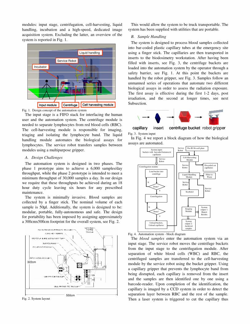
modular, portable, fully-autonomous and safe. The design
for portability has been imposed by assigning approximately
a 300cmx500cm footprint for the overall system, see Fig. 2.
Fig. 2. System layout
This would allow the system to be truck transportable. The
system has been supplied with utilities that are portable.
B. Sample Handling
The system is designed to process blood samples collected
into bar-coded plastic capillary tubes at the emergency site
using a finger stick. The capillaries are then transported in
inserts to the biodosimetry workstation. After having been
filled with inserts, see Fig. 3, the centrifuge buckets are
loaded into the automation system by the operator through a
safety barrier, see Fig. 1. At this point the buckets are
handled by the robot gripper, see Fig. 3. Samples follow an
unmanned series of operations that automate two different
biological assays in order to assess the radiation exposure.
The first assay is effective during the first 1-2 days, post
irradiation, and the second at longer times, see next
Subsection.
Fig. 3. System input
In Fig. 4 we report a block diagram of how the biological
assays are automated.
Fig. 4. Automation system - block diagram
The blood samples enter the automation system via an
input stage. The service robot moves the centrifuge buckets
from the input stage to the centrifugation module. After
separation of white blood cells (WBC) and RBC, the
centrifuged samples are transferred to the cell-harvesting
module by the service robot using the bucket gripper. Using
a capillary gripper that prevents the lymphocyte band from
being disrupted, each capillary is removed from the insert
and the samples are then identified one by one using a
barcode-reader. Upon completion of the identification, the
capillary is imaged by a CCD system in order to detect the
separation layer between RBC and the rest of the sample.
Then a laser system is triggered to cut the capillary thus
Input module Centrifuge
Service Robot
Cell harvesting module
Liquid handling
Incubator
Input module Centrifuge
Service Robot
Cell harvesting module
Liquid handling
Incubator
550cm
322cm
550cm
322cm
capillary insert centrifuge bucket robot grippercapillary insert centrifuge bucket robot gripper
Service
Robot
Centrifugation module
Pre-ID 96-well plate
Load bucket into
centrifuge
Centrifugation
Unload buckets,
Unload capillaries
Liquid Handling
Module
Filter-to-
Waste
Cell-Harvesting
Module
Imaging
Module
System input:
buckets with barcoded hematocrit
capillaries
Y
N
N
Y
System
output 2:
Archived
samples
System
output 1:
Report
Results
Service
Robot
Service
Robot
Done?
Done?
Service
Robot
Service
Robot
Incubator
Discarded cut
capillaries
separating the sample into two parts one of which is
disposed, namely the one with RBC. However, before
performing the cut, the sample is imaged by the CCD system
also for outputting an early assessment of radiation exposure.
The thickness of the lymphocyte band is measured and an
alarm signal is given in output if the value is low, see Fig. 5.
Fig. 5. Sample handling on the cell harvesting module
Each cut capillary, which contains now a sample of WBC
of a single individual, is transferred to a specific well of an
automation-compatible microplate by means of the capillary
gripper which prevents the lymphocytes from falling under
gravity, see Section III. The fully-harvested microplate, now
containing the lymphocyte samples of 96 different
individuals, is then transferred by the service robot onto the
deck of a liquid handling module where the lymphocytes
undergo to a series of washes and reagent addition.
According to the type of biological assay used, the samples
will be transferred to an incubator or a FIFO stacker, see
Section IV. After having completed the biological assay, the
filters of the microplates (to which the samples are attached)
are imaged by a dedicated high-speed acquisition system and
a report is produced summarizing the radiation exposure of a
single individual, see next Subsection. The samples are then
archived.
C. Selection of Biological Assays
Although the range of potential biodosimeters is rather
extensive, most of them are inappropriate for high
throughput automation due to their complexity or the
difficulty to rapidly obtain samples [8, 9]. Out of the assays
described in [8], two assays were chosen as being the most
suitable for use in the robotic biodosimetry workstation: the
micronucleus assay and the γ-H2AX assay.
Micronuclei in lymphocytes
Micronuclei are a well characterized endpoint for
radiation dosimetry and the cytokinesis-blocked
micronucleus assay [10] is recommended as a biodosimeter
by the International Atomic Energy Agency [11]. They have
also recently been shown to be a good predictor of cancer
risk in humans [12]. Elevated micronucleus yields were also
observed in exposed individuals following the incidents at
Chernobyl [13] and Goiânia [14].
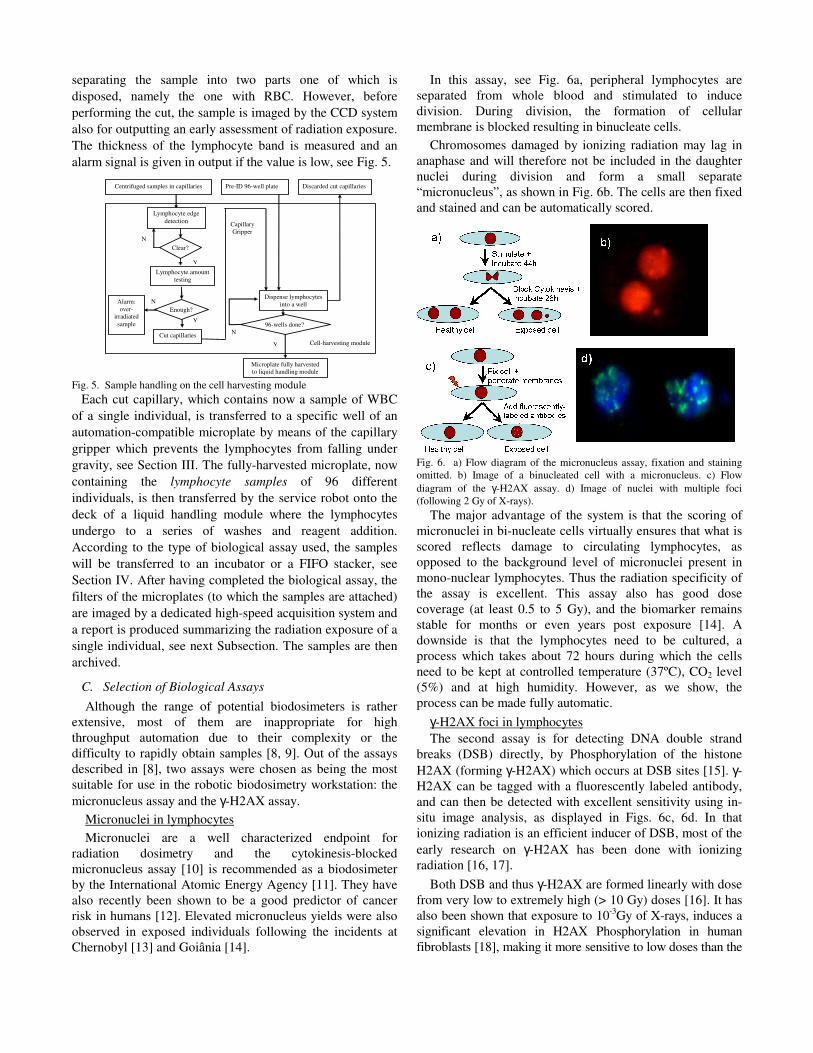
In this assay, see Fig. 6a, peripheral lymphocytes are
separated from whole blood and stimulated to induce
division. During division, the formation of cellular
membrane is blocked resulting in binucleate cells.
Chromosomes damaged by ionizing radiation may lag in
anaphase and will therefore not be included in the daughter
nuclei during division and form a small separate
“micronucleus”, as shown in Fig. 6b. The cells are then fixed
and stained and can be automatically scored.
Fig. 6. a) Flow diagram of the micronucleus assay, fixation and staining
omitted. b) Image of a binucleated cell with a micronucleus. c) Flow
diagram of the γ-H2AX assay. d) Image of nuclei with multiple foci
(following 2 Gy of X-rays).
The major advantage of the system is that the scoring of
micronuclei in bi-nucleate cells virtually ensures that what is
scored reflects damage to circulating lymphocytes, as
opposed to the background level of micronuclei present in
mono-nuclear lymphocytes. Thus the radiation specificity of
the assay is excellent. This assay also has good dose
coverage (at least 0.5 to 5 Gy), and the biomarker remains
stable for months or even years post exposure [14]. A
downside is that the lymphocytes need to be cultured, a
process which takes about 72 hours during which the cells
need to be kept at controlled temperature (37ºC), CO2 level
(5%) and at high humidity. However, as we show, the
process can be made fully automatic.
γ-H2AX foci in lymphocytes
The second assay is for detecting DNA double strand
breaks (DSB) directly, by Phosphorylation of the histone
H2AX (forming γ-H2AX) which occurs at DSB sites [15]. γ-
H2AX can be tagged with a fluorescently labeled antibody,
and can then be detected with excellent sensitivity using in-
situ image analysis, as displayed in Figs. 6c, 6d. In that
ionizing radiation is an efficient inducer of DSB, most of the
early research on γ-H2AX has been done with ionizing
radiation [16, 17].
Both DSB and thus γ-H2AX are formed linearly with dose
from very low to extremely high (> 10 Gy) doses [16]. It has
also been shown that exposure to 10-3
Gy of X-rays, induces a
significant elevation in H2AX Phosphorylation in human
fibroblasts [18], making it more sensitive to low doses than the
Cell-harvesting module
Centrifuged samples in capillaries
Alarm:
over-
irradiated
sample
Clear?
Lymphocyte amount
testing
Enough?
Cut capillaries
Pre-ID 96-well plate Discarded cut capillaries
Dispense lymphocytes
into a well
96-wells done?
Y
N
Y
N
N
Y
Capillary
Gripper
Microplate fully harvested
to liquid handling module
Lymphocyte edge
detection

micronucleus assay. No data have yet been published for γ-
H2AX foci in human lymphocytes.
The γ-H2AX system well complements the micronucleus
system as a radiation biodosimeter [19], requiring much
shorter processing times as the cells do not have to be
cultured 72 hours for the assay. Furthermore, the γ-H2AX
foci reach their maximum value within about 30 minutes of
irradiation [19], decaying over 24-36 hours post-exposure
[20] this is contrasted with micronuclei that appear about 24
hours post-exposure and decay over months or years [14].
D. Throughput Requirements
The phase 1 prototype is currently under development and
it is the focus of this paper. Nevertheless, we report also the
phase 2 prototype specifications in this Subsection. The
allowable centrifugation time is estimated for different sizes
of the centrifugation batch, see Fig. 7. The phase 1 system
features a 20-minute centrifugation at 40g with temperatures
between 4ºC and 37 ºC.
Fig. 7. Allowable centrifugation time.
The cell-harvesting and imaging module have been
identified as the bottleneck of the system. These modules
process samples individually while the rest of the
biodosimetry components process several samples in parallel
(e.g. 96, 384 and 576 samples).
The phase 2 system is designed to use a two-speed
configuration protocol, equivalent to an 8-minute
centrifugation at 40g followed by a 3-minute centrifugation
at 160g. Sharp separation is obtained with the phase 1
centrifugation protocol, as shown in Fig. 8, while the phase 2
centrifugation protocol is currently being refined. As far as
the remaining modules are concerned, the phase 1 system
specifications impose a throughput of 10 sec/sample.
However, the phase 2 system specifications assign a 2
sec/sample throughput. In order to verify that the current
prototype, see Section V, would be compliant with the phase
2 system specification, throughput experiments were
performed with the cell-harvesting module. Particular focus
was given to the laser-based separation of lymphocytes from
RBC. Experiments conducted with the current prototype
resulted in a separation time of 2.5 seconds with a rotational
speed of the capillary of 30 rpm and a laser power of 0.53
Watt. A design of experiments is undergoing for identifying
the optimal parameters, namely rotational speed and laser
power, which return a minimum separation time. The
conceptual design, not reported here, of a multi-capillary
gripper capable of simultaneously gripping 24 capillaries at a
time and of a gravity/back-fed capillary holder for the phase
2 system is also carried-out. Provision for the existing liquid
handling module has been made in order to use a 384-
position dispenser for the phase 2. For the phase 1 system a
robotic incubator capable of simultaneously hosting 220
microplates has been selected: the STX220 from Liconic Inc.
Fig. 8. Centrifuged capillary showing red blood cells (RBC - bottom) and
WBC band.
III. CENTRIFUGATION MODULE AND MULTI-PURPOSE
GRIPPER
The design of the input stage is shown in Fig. 9a. This
subsystem is responsible for moving four centrifuge buckets
at the pick location of the service robot.
Fig. 9. Input stage: a) loading and b) safe user access. Centrifuge module:
c) unloading and d) loading
In the current design, four centrifuge buckets are filled
with three inserts, each carrying 48 capillaries, for a total
batch of 576 capillaries per centrifugation cycle. When the
centrifugation ends, the service robot transfers the empty
centrifuge buckets back on the input stage after capillaries
have been transferred to the cell-harvesting module. The
input stage is also responsible for simultaneously i) moving
the used centrifuge buckets (without capillaries) out of the
system and ii) introducing a new set of centrifuge buckets
(filled with capillaries) by performing a 180o rotation. This
ensures continuity of the input to the automatic system. The
input stage serves as a point of interface with the human user
who is separated by the automation system by a safety wall,
see Fig. 9b. The service robot is responsible for moving the
buckets, one by one, from the input stage to the centrifuge
module, see Figs. 9c-d. The reach of the service robot is
augmented by a custom-made link endowed with a
Allowable Centrifugation Time
(30000 samples in 18 hours per day)
3.456
6.91210.368
13.824
17.2820.736
24.192
27.64831.104
34.5638.016
41.472
44.92848.384
51.84
55.29658.752
62.208
65.664
0
10
20
30
40
50
60
70
96 192 288 384 480 576 672 768 864 960 1056 1152 1248 1344 1440 1536 1632 1728 1824
Number of Capillaries Each Centrifugation
Ce
ntr
ifu
ga
tio
n T
ime
(m
in)

multipurpose gripper capable of i) capillary handling and of
ii) buckets and microplates handling. The capillary gripper is
composed of a passive spring-plunger-collet unit and of an
active gear-motor-shaft unit. The former is responsible for
gripping the capillary without the use of any motor. The
latter is responsible for the rotation of the capillary during
cutting in order to guarantee an even distribution of the
power, thus minimizing thermal effects and contamination
generated by the laser-based cutting.
The bucket/microplate gripper is composed of a
pneumatically-actuated two-jaw unit and two miniature self-
contained photoelectric sensors, namely two 06 38F from
Banner Engineering Corp. Each jaw is composed of two
sections: one for gripping the bucket and one for gripping the
plate. The former is a custom-made jaw that seats into the
side slots of the bucket when grip takes place. The latter is a
rubber-padded jaw that grips microplates.
The centrifuge will be equipped with an electro-
mechanical clutch that locks the rotor in place after it stops
rotating. The optical sensors are in charge of detecting the
centrifuge rotor arm. This operation guarantees a reference
to the gripper when loading the buckets in the centrifuge.
The gripper design, see Fig. 10, is modular and lightweight.
Fig. 10. a) Mulipurpose gripper. b) capillary gripper and rotary stage. c)
capillary gripper
The hollow structure allows for the passage of both
pneumatic and electrical lines. The link length can be easily
changed without having to change the mechanical interface
with the robot. The two grippers, capillary and
bucket/microplate, can be mounted independently on the
service robot flange. Details on the design of the capillary
gripper mechanism are reported in Fig. 10. When the
capillary is gripped, the collet slides onto the capillary
performing a vertical move thanks to the built-in linear
actuator of the service robot. The gripping operation ends
when the capillary comes into contact with the tip of the
plunger. The latter prevents the lymphocytes to fall under
gravity after cutting the capillary. The plunger is also
endowed with air-conductive channels that allow dispensing
positive pressure for transferring lymphocytes into the
microplate well after the capillary has been cut, i.e. after
RBC have been removed.
IV. CELL-HARVESTING AND LIQUID HANDLING MODULES
After centrifugation, centrifuge buckets are transferred to
the cell-harvesting module by the service robot using the
bucket gripper. The cell-harvesting module is responsible for
obtaining the lymphocytes from centrifuged blood samples,
see Fig. 11.
Fig. 11. Cell harvesting module
The cell-harvesting module consists of a laser system with
a galvo head, a barcode reader, a Hawkeye 1525 from RVSI,
a CCD camera, a CV-M4+CL from JAI (in combination with
a frame grabber, a 1426 from National Instruments) for
image segmentation, see Fig. 12, and a custom-made holder
for microplates and centrifuge buckets.
Fig. 12. Image segmentation of capillary. Note outline around RBC layer in
b) and d).
The barcode reader identifies the capillary right before the
CCD imaging. The barcoded capillaries have been registered
at the collection site by using a commercial tracking and
database system, like the EMTrack (patient tracking) by
EMSystem. The barcode reader allows tracking the sample
after it has been transferred to a pre-id microplate. The
holder hosts i) three microplate stacks, each made of 21
microplates, ii) four centrifuge buckets iii) a microplate
reference location, where the wells are filled with
lymphocytes iv) a gravity-based capillary disposal unit.
The inputs to the module are centrifuged capillaries in
buckets and sterile automation-compliant microplates. The
outputs of the system are cut capillaries, which are disposed,
and microplates containing lymphocytes transferred from
Nd: YVO4
LASER CAVITY
GALVO HEAD
CAMERA AND BARCODE READER
DISPOSAL OF
CUT CAPILLARIES
MICROPLATES
CENTRIFUGED
BUCKETS
Nd: YVO4
LASER CAVITY
GALVO HEAD
CAMERA AND BARCODE READER
DISPOSAL OF
CUT CAPILLARIES
MICROPLATES
CENTRIFUGED
BUCKETS
Uppersupport
Snap ring
Shaft
Collet
Plunger
Spring
Connector
Snap ring
Gear
BearingBearingcover
Motor
Bucket/Microplate gripper
Capillary gripper
b) c)
a)
Mounting plate for service robot interface
Compressed Air
Uppersupport
Snap ring
Shaft
Collet
Plunger
Spring
Connector
Snap ring
Gear
BearingBearingcover
Motor
Bucket/Microplate gripper
Capillary gripper
b) c)
a)
Mounting plate for service robot interface
Uppersupport
Snap ring
Shaft
Collet
Plunger
Spring
Connector
Snap ring
Gear
BearingBearingcover
Motor
Bucket/Microplate gripper
Capillary gripper
b) c)
a)
Uppersupport
Snap ring
Shaft
Collet
Plunger
Spring
Connector
Snap ring
Gear
BearingBearingcover
Motor
Bucket/Microplate gripper
Capillary gripper
Uppersupport
Snap ring
Shaft
Collet
Plunger
Spring
Connector
Snap ring
Gear
BearingBearingcover
Motor
Uppersupport
Snap ring
Shaft
Collet
Plunger
Spring
Connector
Snap ring
Uppersupport
Snap ring
Shaft
Collet
Plunger
Spring
Connector
Snap ring
Gear
BearingBearingcover
Gear
BearingBearingcover
Motor
Bucket/Microplate gripper
Capillary gripper
Bucket/Microplate gripper
Capillary gripper
b) c)
a)
Mounting plate for service robot interface
Compressed Air
Compressed Air

capillaries. Two software-outputs are the data associated
with the barcode-based identification of the capillaries and to
the lymphocyte thickness estimation. The operation of the
module follows a sequential routine outlined below.
The microplate gripper transfers a multi-well plate from
the stack to the reference location. The capillary gripper is
then deployed to service each capillary. The capillary is
moved in the field of view of the barcode reader for
identification. After reading, a vertical move is performed by
the service robot and the capillary is moved in the field of
view of a CCD camera for detection of the separation band
between RBC and the rest of the sample. Upon detection of
the band, the laser performs the cut while the capillary is
rotated by the rotary stage of the gripper. During imaging, an
estimation of the lymphocyte band thickness is also
performed by using the same machine vision system. Upon
cutting the capillary, the part containing RBC is disposed
into a biohazard waste container by means of gravity, see
Fig. 13. The cut capillary, containing lymphocytes and
plasma, is moved above the well of the microplate in the
reference location where lymphocytes are dispensed using
the capillary gripper. The cut capillary is then disposed into a
biohazard waste container. During this operation the service
robot will move downward while the collet will move
upward until the inner wall of the collet is in contact with the
outer surface of the capillary. When the foregoing contact
ends the capillary falls under gravity. The capillary will then
be disposed into a biohazard waste container. Once a multi-
well plate is fully harvested the service robot transfers it to
the liquid handling module, see Fig. 14.
Fig. 13. Cell-harvesting module – detailed top view
The liquid handling module is responsible for the
automation of both micronuclei and γ-H2AX assays for
lymphocytes. This is accomplished by a sequence of washes
and reagent addition. As the phase 1 system is designed for a
throughput of 6,000 samples per day, using 96-well plates,
and the assay duration is 72hr approximately, the incubator
should be capable of storing at least 189 microplates
simultaneously. To this effect the STX220 incubator is
integrated with the liquid handling module as shown in Fig.
14. While running the micronucleus protocol, see Subsection
II.C, the service robot places the microplate in the lower left
position on the deck of the liquid handling robot. After a
wash and the addition of culture medium the microplate is
transferred to the incubator. The microplate is then
transferred back to the liquid handling robot for the addition
of Cytochalasin-B. The microplate is then transferred into
the incubator for the last incubation cycle. After the latter the
protocol continues in the liquid handling module. In the case
of γ-H2AX protocol, see Subsection II.C, the initial
operation consists of moving the microplate to the lower left
position of the liquid handling robot. After a wash and the
addition of the permealization buffer, the microplate is
transferred to a FIFO stacker for 20 minutes. The plate then
moves back to the liquid-handling robot where blocking
reagents are added. The microplate is then transferred back
on to the FIFO stacker for other 30 minutes and then returns
to the liquid-handling robot deck. Then the protocol
continues on the liquid handling robot.
The fully-integrated liquid handling module is composed
of a gantry system, an ultrasonic wash-station, a bulk-
dispenser, a positive pressure unit, a filter-to-waste unit, a
fixed-cannula array and a microplate gripper. The gantry
system moves the microplate gripper, the fixed-cannula array
(or the positive pressure unit) and the bulk dispenser at one
of the specified microplate locations on the operation deck.
The filter-to-waste unit collects the result of the well washes.
The ultrasonic wash-station guarantees avoidance of reagent-
mixing by washing the metallic fixed-cannula array tips
before changing reagent. The microplate gripper moves the
plates or/and their lids across the deck.
Fig. 14. Sample transfer from liquid handler to robotic incubator
V. PROTOTYPE
In order to develop the prototype, see Fig. 15, a room was
selected in such a way to impose dimensional constraints that
would increase system portability.
The automated biodosimetry room is located in the Mudd
Engineering building at Columbia University Morningside
Campus within the Department of Mechanical Engineering.
The biodosimetry workstation features an RS80 from Staubli
Inc., an O-Sprey UV laser system from Quantronix, a
Sciclone ALH 3000 from Caliper Life Sciences Inc., a
5810RA centrifuge from Eppendorf AG and a main frame
computer from iBASE Technology Inc. running the RTAI
for Linux for the low level control.
The specific liquid handler was selected for the following
characteristics that meet the biodosimetry requirements: i)
bulk reagent dispenser is capable of continuously dispensing
10-2,500µl of a single reagent simultaneously in eight wells
with a coefficient of variation less than 2-3%, ii) fixed-
cannula array guarantees the same coefficient of variation
and it is capable of dispensing up to 25 µl of a reagent
simultaneously in 96 wells, iii) absence of disposable tips is

intentional in the design of the system1. The foregoing
SCARA robot was selected for its open architecture
controller and for the +/-0.025mm repeatability, needed for
the robotic-assisted laser-based cutting. The above-
mentioned laser machine was chosen because the system is
capable of barcoding and cutting plastic capillary tubes.
Finally the specific centrifuge was selected because it meets
the requirements of temperature control and throughput.
Fig. 15. Prototype
Several custom-made components have been designed,
namely an automatic centrifuge brake and lid, two grippers
(bucket and capillary), the input stage and cell harvesting
sub-component fixtures and layout.
VI. CONCLUSION
This paper presented an overview of an ongoing project
on developing a novel high throughput automation system
for radiation biodosimetry. The driving clinical needs, the
alternatives for processing the incoming blood samples using
γ-H2AX or micronuclei assays, and the corresponding
automation cycles for a single incoming micro-pipette were
detailed. The key robotic components of this automation
system were presented together with custom designed
multipurpose grippers and a novel cell harvesting module.
The grippers were designed to accept micro-pipettes,
centrifuge buckets, and microplates. The cell-harvesting
module was designed to harvest the lymphocytes from a
centrifuged micro-pipette while using vision algorithms to
segment the lymphocyte layer and to detect low lymphocyte
volumes in patient samples that require triage. The cell-
harvesting module also included a laser machine for
contactless cutting of micropipettes.
1 Relying on this type of consumables would strongly hamper the use in
an emergency condition of the system. The use of metallic tips makes the
system operation independent on the availability of disposable tips.
Although this paper is focused on automation for high
throughput biodosimetry, we believe that the system at hand
is relevant to many automation systems geared towards high
throughput handling of blood samples. As a matter of fact
the biodosimetry workstation can be used in the γ-H2AX
configuration with modified reagents for detecting the
presence and inter-cell distribution of other proteins and can
therefore be used for mass screening of various diseases such
as cancer, HIV or Hepatitis.
REFERENCES
[1] International Atomic Energy Agency, The radiological accident at
Goiânia, ed. I.A.E.A. 1988, Vienna.
[2] T.C. Pellmar and S. Rockwell, Priority list of research areas for
radiological nuclear threat countermeasures. Radiation Research,
2005. 163: p. 115-123.
[3] Meldrum, D.R., et al., Sample Preparation in Glass Capillaries for
High-Throughput Biochemical Analyses, in International Conference
on Automation Science and Engineering. 2005: Edmonton, Canada.
[4] V. Kachel, G.Sindelar, and S. Grimm, High-throughput isolation of
ultra-pure plasmid DNA by a robotic system. BMC Biotechnology,
2006. 6(9).
[5] Prasanna, P.G.S., et al., Cytogenetic Biodosimetry for Radiation
Disasters: Recent Advances. 2005, Technical Report. (AFRRI CD 05-
2). Armed Forces Radiobiology Research Institute.
[6] Soldatova, L.N., et al., An ontology for a robot scientist.
Bioinformatics, 2006. 22(14): p. 464-471.
[7] Hayata, I., et al., Robot system for preparing lymphocyte
chromosome. J. Radiation Research, 1992. 33(Supplement): p. 231-
241.
[8] Amundson, S.A., et al., Biological indicators for the identification of
ionizing radiation exposure in humans. Expert Rev. Mol. Diagn.,
2001. 1: p. 211-219.
[9] Durante, M., Potential applications of biomarkers of radiation
exposure in nuclear terrorism events. Phisica Medica, 2003. XIX(3):
p. 191-212.
[10] M. Fenech and A.A. Morley, Measurement of Micronuclei in
Lymphocytes. Mutation Research, 1985. 147(1-2): p. 29-36.
[11] International Atomic Energy Agency, Cytogenetic analysis for
radiation dose assessment : a manual, ed. I.A.E.A. 2001, Vienna.
127 p.
[12] Bonassi, S., et al., An increased micronucleus frequency in
peripheral blood lymphocytes predicts the risk of cancer in humans.
Carcinogenesis, 2007. 28(3): p. 625-631.
[13] Livingston, G.K., et al., Radiobiological evaluation of immigrents
from the vicinity of Chernobyl. International Journal of Radiation
Biology, 1997. 72: p. 703-713.
[14] da Cruz, A.D., et al., Human micronucleus counts are correlated with
age, smoking and cesium-137 dose in the Goiânia (Brazil)
radiological accident. Mutation Research, 1994(313): p. 57-68.
[15] Rogakou, E.P., et al., DNA Double-stranded Breaks Induce Histone
H2AX Phosphorylation on Serine 139. J. Biol. Chem., 1998. 273(10):
p. 5858-5868.
[16] MacPhail, S., et al., Expression of phosphorylated histone H2AX in
cultured cell lines following exposure to X-rays. International Journal
of Radiation Biology, 2003. 79(5): p. 351-358.
[17] Rogakou, E.P., et al., Megabase chromatin domains involved in DNA
double-strand breaks in vivo. J. Cell Biol., 1999. 146: p. 905-916.
[18] K. Rothkamm and M. Lobrich, Evidence for a lack of DNA double-
strand break repair in human cells exposed to very low X-ray doses.
Proc. Natl. Acad. Sci. USA, 2003. 100: p. 5057-5062.
[19] Pilch, D.R., et al., Characteristics of gamma-H2AX foci at DNA
double strand breaks sites. Biochemistry and cell biology, 2003.
81(3): p. 123-129.
[20] J. P. Banath, S. H. Macphail, and P.L. Olive, Radiation sensitivity,
H2AX phosphorylation, and kinetics of repair of DNA strand breaks
in irradiated cervical cancer cell lines. Cancer Research, 2004. 64: p.
7144-7149.