design consideration of beam ducts for...
TRANSCRIPT

DESIGN CONSIDERATION OF BEAM DUCTS FOR QUADRUPOLE CORRECTORS IN J-PARC RCS
J. Kamiya#, M. Kinsho, N. Hayashi, H. Hotchi, N. Ogiwara, N. Tani, and Y. Watanabe JAEA/J-PARC, Tokai, Naka, Ibaraki, Japan
Abstract
In J-PARC 3GeV synchrotron (RCS), new quadrupole magnets (quadrupole correctors) are planned to be installed in order to correct the edge focusing effect and tune. In this report, we describe a deliberation flow about the design of the beam ducts, which is installed in the quadrupole corrector. The effects of eddy current were examined in the case of the titanium duct. The calculated results showed that the temperature rise was too much (up to over 350oC) and the magnetic field in the beam duct is largely distorted. Therefore we decided to employ an alumina ceramics beam duct. The stress and displacement, which are caused by the atmospheric pressure, were estimated by simulating the realistic equipments in the beam line. It was found that there was no large stress and displacement by installing the alumina ceramics duct.
INTRODUCTION New quadrupole magnets are planned to be installed in
J-PARC 3GeV synchrotron (Rapid Cycling Synchrotron: RCS) during the shutdown in 2013. The new quadrupole magnets have two roles. One is to correct unwanted edge focusing effect at the entrance and exit of the injection bump magnets [1]. The other is to correct tune, which changes during the beam acceleration period of 20 ms, in order to keep the beam inside stability region in the tune space [2]. In order to achieve these purposes, six quadrupole correctors are installed at both ends of each long straight section as shown in the past report [1]. Bore diameter and the pole length of the quadrupole correctors is 290 mm and 150 mm, respectively [3]. Time response of the magnetic field of the quadrupole correctors are shown as a black curb in Fig. 1. The repetition rate is 25 Hz.
This report is aimed to show the examination items and results of the examination in designing beam duct, which are installed in the aperture of the quadrupole correctors. For design consideration of the beam duct, we take the following steps. First we start with a titanium duct. The effect of the eddy current is anticipated to be large because of the large time rate of change of the magnetic field (maximum 318 T/s at a duct position). Therefore we examine the magnetic field distortion inside a titanium duct and the thermal distribution of the duct, which are caused by the eddy current. If the thermal elevation and the magnetic field distortion are too large, we select the alumina ceramics for the material of the vacuum chamber. In that case, we have to examine the stress originating from the atmospheric pressure by using a model of the realistic beam line in order to verify that the maximum
stress and the displacement are not too large. From above aspects, first we will mention about the
effect of the eddy current when we use a titanium duct. Second, we will mention about the structure analysis to examine the stress and displacement in the case that an alumina ceramics duct is installed in the beam line. Finally, the design of the beam duct will be mentioned.
Figure 1: Black curb: time response of the absolute magnetic field of the quadrupole corrector. Red dotted curb: corresponding power, which is generated in a titanium duct by the eddy current.
EXAMINATION IN DESIGNING THE BEAM DUCT
Examination of the Eddy Current Effect in the Case of Titanium Duct
Designing the beam duct for the quadrupole corrector, we begin to consider with pure titanium as a duct material. Pure titanium is used for the beam ducts and bellows in J-PARC because of its low activation and good vacuum characteristics [4]. In order to reduce the eddy current, the thickness of the duct wall should be as thin as possible. Circumferential stress for a thin cylinder t is given as σ = , where each symbol represents p: pressure, r:
radius, t: thickness, respectively. Buckling load for a thin
cylinder t,cr is given as σ , = , where each
symbol represents E: Young modulus (106 MPa for titanium), : Poisson ratio (0.34 for titanium), respectively. Table 1 shows circumferential stress and bucking load for a thin cylinder changing the thickness of the wall. When the wall thickness is less than ~2.1 mm, the circumferential stress becomes larger than buckling load, which means the cylinder collapses.
0
0.05
0.1
0.15
0.2
0
1 104
2 104
3 104
4 104
0 5E-3 1E-2 1.5E-2 2E-2
|GL
| [T
] Po
wer [W
]
Time [sec]
Edge focus correctionduring injection
Tune correctionduring acceleration
{
___________________________________ #[email protected]
Proceedings of IPAC2013, Shanghai, China THPFI016
07 Accelerator Technology and Main Systems
T14 Vacuum Technology
ISBN 978-3-95450-122-9
3327 Cop
yrig
htc ○
2013
byJA
CoW
—cc
Cre
ativ
eC
omm
onsA
ttri
butio
n3.
0(C
C-B
Y-3.
0)
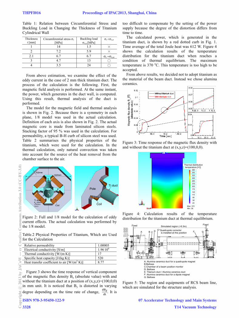
Table 1: Relation between Circumferential Stress and Buckling Load in Changing the Thickness of Titanium Cylindrical Wall
Thickness t [mm]
Circumferential stress t
[MPa] Buckling load t,cr [MPa]
t t,cr
1 14 1.5 × 2 7.2 5.9 ×
2.1 6.7 6.7 t t,cr 3 4.7 13 ○ 4 3.5 24 ○
From above estimation, we examine the effect of the
eddy current in the case of 2 mm thick titanium duct. The process of the calculation is the following. First, the magnetic field analysis is performed. At the same instant, the power, which generates in the duct wall, is computed. Using this result, thermal analysis of the duct is performed.
The model for the magnetic field and thermal analysis is shown in Fig. 2. Because there is a symmetry in each plane, 1/8 model was used in the actual calculation. Definition of each axis is also shown in Fig. 2. The actual magnetic core is made from laminated silicon steels. Stacking factor of 95 % was used in the calculation. For permeability, a typical B-H curb of silicon steel was used. Table 2 summarises the physical properties of the titanium, which were used for the calculation. In the thermal calculation, only natural convection was taken into account for the source of the heat removal from the chamber surface to the air.
Figure 2: Full and 1/8 model for the calculation of eddy current effects. The actual calculation was performed by the 1/8 model.
Table.2 Physical Properties of Titanium, Which are Used for the Calculation
Relative permeability 1.00005 Electrical conductivity [S/m] 1.96.106 Thermal conductivity [W/(m K)] 17 Specific heat capacity [J/(kg K)] 520 Heat transfer coefficient to air [W/(m2 K)] 8.77
Figure 3 shows the time response of vertical component
of the magnetic flux density By (absolute value) with and without the titanium duct at a position of (x,y,z)=(100,0,0) in mm unit. It is noticed that By is distorted in varying
degree depending on the time rate of change, . It is
too difficult to compensate by the setting of the power supply because the degree of the distortion differs from time to time.
The calculated power, which is generated in the titanium duct, is shown by a red dotted curb in Fig. 1. Time average of the total Joule heat was 612 W. Figure 4 shows the calculation results of the temperature distribution for the titanium duct when reaches a condition of thermal equilibrium. The maximum temperature is 370 oC. This temperature is too high to be accepted.
From above results, we decided not to adopt titanium as the material of the beam duct. Instead we chose alumina ceramics.
Figure 3: Time response of the magnetic flux density with and without the titanium duct at (x,y,z)=(100,0,0).
Figure 4: Calculation results of the temperature distribution for the titanium duct at thermal equilibrium.
Figure 5: The region and equipments of RCS beam line, which are simulated for the structure analysis.
Coil
Ti ductPole
Thermal distributiontemperature [oC]
380
350
320
290
260
230
200
170
140
110
80
50
20
Max: 372Min: 38Max
Min
A: Alumina ceramics duct for a quadrupole magnetB:BellowsC:Chamber of a beam position monitorD: BellowsE: Titanium duct / Alumina ceramics ductF: Alumina ceramics duct for a dipole magnetG: Bellows
Simulated region (~6.3m)
A B C D EF G
Fixed Fixed
*Quadrupole correctoris installed at this position
THPFI016 Proceedings of IPAC2013, Shanghai, China
ISBN 978-3-95450-122-9
3328Cop
yrig
htc ○
2013
byJA
CoW
—cc
Cre
ativ
eC
omm
onsA
ttri
butio
n3.
0(C
C-B
Y-3.
0)
07 Accelerator Technology and Main Systems
T14 Vacuum Technology

Table 3: Maximum Stresses [Mpa] in Each Equipment. Symbol A-G Corresponds to the Equipment ID in Fig. 5
A B C D E F G Case 1 21.6 17.7 12.4 6.6 30.5 56.4 42.1 Case 2 21.3 13.7 10.4 10.9 17.8 56.4 38.3
Figure 6: The contour figures of the displacements. Symbols A-G correspond to the equipments in Fig. 5.
Structure Analysis in the Case of Alumina Ceramics Duct
For alumina ceramics duct, we have many experiences to produce them in J-PARC [5,6]. And the shape of the beam duct for the quadrupole corrector (simple cylinder) is not so difficult to produce comparing with the mass-produced ceramics duct [6]. However, it is very important to examine the stress and displacement, which is generated by the atmospheric pressure in actual beam line. Therefore the structure analysis was performed about one of the six regions, where the quadrupole correctors are installed.
Figure 5 shows the object region and equipments of the RCS beam line. The equipments in the region between two fixed points, which are anchored by the support post of stainless steel, were simulated. The calculation was performed for two cases. One (case 1) is about the present system, where the titanium duct is installed at the position E in Fig. 5. The other (case 2) is about the upgraded system, where the alumina ceramics duct is installed in E. While the titanium vacuum chamber is anchored by the support post, it is impossible to make such a fixed point for the alumina ceramics duct. Therefore the alumina ceramics duct is installed on the support, which is made from glass fibre re-inforced epoxy resin. The support of each equipment was also simulated. Here, not mention the details of the boundary conditions, the both ends of the simulated region and the lower part of each support were
set to be fixed. The atmospheric pressure and the weight of the equipments were taken into account for the loading conditions.
The maximum stresses in each equipment are summarized in Table 3. Figure 6 shows the contour figures of the displacements. There is almost no difference of the stress due to the replacement of vacuum chamber and the supports. The stress for the alumina ceramics is much lower than its fracture strength [6]. The displacement of each equipment becomes less after installing the vacuum chamber for the quadrupole corrector, which is because the body of the vacuum chamber is firmly supported by two supports of glass fibre re-inforced epoxy resin.
DESIGN OF THE BEAM DUCT FOR THE QUADRUPOLE CORRECTOR
We briefly mention about the design of the alumina ceramics vacuum chamber. Figure 7 shows the outline view of the alumina ceramics vacuum chamber for the quadrupole corrector. Total length of the chamber is set to 675 mm. A bellows should be put in this length in order to easily attach to the adjacent equipment without applying a load to the ceramics chambers. Therefore the bellows is directly welded to the sleeve, which is brazed to the metalized end face of the alumina ceramics chamber. The sleeves, flanges, and bellows are made from pure titanium. For the RF shield, copper foil of 0.5 mm thickness and 5 mm width are held onto outside of the alumina ceramics duct with two-component epoxy resin. Capacitors are welded in order to electrical contact between RF shield and the titanium flanges. Inner surface of the alumina ceramics are coated by TiN in order to reduce the secondary electron coefficient of the surface. The thickness of the TiN coating is 10-50 nm. Detail of the manufacturing process is written in [5,6]. Now the first chamber was successfully produced and under some tests. We will produce all six chambers until the end of this year.
Figure 7: Outline view of the alumina ceramics duct for the quadrupole corrector.
REFERENCES [1] H. Hotchi, et al., Proceedings of HB2012, Beijing, China,
MOP211. [2] H. Hotchi, private communication. [3] N. Tani, private communication. [4] N. Ogiwara, Proceedings of IPAC2011, San Sebastian, Spain,
971. [5] M. Kinsho, et al., Vacuum 81 (2007) 808. [6] M. Kinsho, et al., Vacuum 73 (2004) 175.
Proceedings of IPAC2013, Shanghai, China THPFI016
07 Accelerator Technology and Main Systems
T14 Vacuum Technology
ISBN 978-3-95450-122-9
3329 Cop
yrig
htc ○
2013
byJA
CoW
—cc
Cre
ativ
eC
omm
onsA
ttri
butio
n3.
0(C
C-B
Y-3.
0)