design concept of the bridge for manageing the river3whrm-kamoto.com/assets/files/design concept of...
TRANSCRIPT

Design Concept of the Bridge for managing the river
Kamoto MinoruChief Researcher, ICHARM
23 May 2013
1
Contents of this PPT (53 slides)Contents of this PPT (53 slides)
1. Damage of Bridges2. River and Discharge2. River and Discharge3. Permission by River Law & Dike/Revetment4. Bridge Design5 Other Examples5. Other Examples
2

Unique features of Japan’s rivers When it rains, water flows into rivers, resulting in rapid elevation in water level.
Flooding (July 3, Yamakuni River, Yamakunigawa waterway)Kyushu Regional Bureau, MLITg ( y , , g y)
Sogi, Honyabakei-town
Sogi, Honyabakei-towny y
Aono-Zenkai Bridge, located at 16.4 km on the left bank of the Yamakuni River
Normal water level near the Aono-Zenkai Bridge
Aono-Zenkai Bridge, located at 16.4 km on the left bank of the Yamakuni River
Swollen stream near the Aono-Zenkai Bridge(J l 3 10 40AM)
Photo 1-1 Normal Photo 1-2 Flooded3
(July 3 10:40AM)
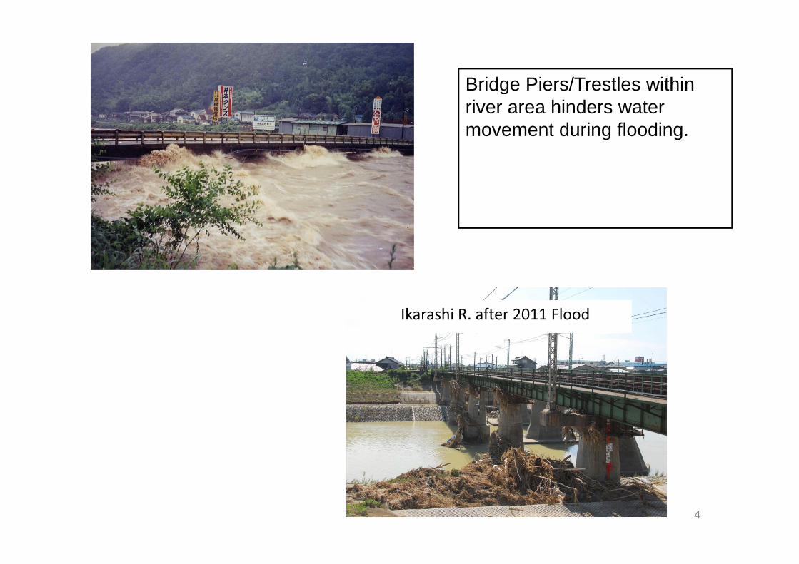
Bridge Piers/Trestles withinBridge Piers/Trestles within river area hinders water movement during flooding.
Ikarashi R. after 2011 Flood
4

Photo 2‐1 dam up the water level and detour /circuit stream by bridge pier(example at Agaga River)(example at Agaga River)
Photo 2‐2 Complex stream around bridge pier (example at Kokai river)
5

Photo 2‐3 Collapse of bridge by score of abutment
6
p g y(example of Yosasa river)

Photo 2‐4 Collapse of bridge by local scour of
7
Photo 2 4 Collapse of bridge by local scour of surrounding pier(example at Fuji river)

Photo 1‐5 Local scour of surrounding pier(example at Sakawa river)
Source of photos : Manual for planning river-crossing bridge constructions (preliminary version; published i J l 2009 b th J I tit t f C t ti E i i ; JICE bli ti N 109001)
8
in July 2009 by the Japan Institute of Construction Engineering; JICE publication No. 109001)

Brake 1
サツキ(皐月)
ツツジ(躑躅) l
9
ツツジ(躑躅):azalea
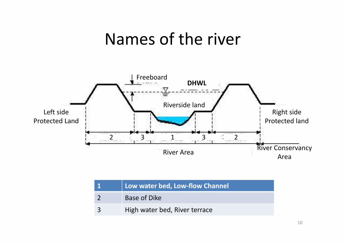
Names of the riverNames of the river
FreeboardDHWL
Riverside landRight side
Protected landLeft side
Protected Land
River Conservancy
Protected landProtected Land
2 3 1 3 2
River Area River Conservancy Area
1 Low water bed, Low‐flow Channel
2 Base of Dike
3 High water bed, River terrace
10

Classification of River AdministratorsClassification of River Administrators
11

Specific Discharge MethodThe specific discharge is the flood peak discharge per unit catchment area.
Generally the specific discharge for small rivers is comparatively larger than that ofGenerally, the specific discharge for small rivers is comparatively larger than that of the bigger rivers.
Q = A q (q = Q/A) Equation (a)Q = A q (q = Q/A) Equation (a)Where :q : specific discharge (m3/s/km2)Q : design discharge (m3/s)
)1( 048.0−A
Q : design discharge (m /s)A : catchment area (km2)
)1( −⋅= AAcq Equation (b) Where: c : constant (Table 5.2a)A t h t (k 2)A : catchment area (km2).
Table : Constant (c ) for Regional Specific Discharge
Region Return Period2-year 5-year 10-year 25-year 50-year 100-year15 66 17 48 18 91 21 51 23 83 25 37
( ) g p gCurve in Philippines
12
15.66 17.48 18.91 21.51 23.83 25.37Visayas 6.12 7.77 9.36 11.81 14.52 17.47
8.02 9.15 10.06 11.60 12.80 14.00
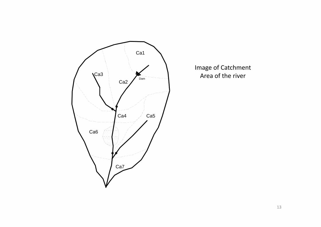
Ca1
Ca2Ca3
Dam
Image of Catchment Area of the river
Ca4 Ca5
Ca6
C 7Ca7
13

Generally, the specific discharge for small rivers is comparatively larger than that of the bigger rivers The specific discharge curve explains this From this curve designthe bigger rivers. The specific discharge curve explains this. From this curve, design discharge is roughly calculated even without any runoff analysis. The reliability of the design discharge estimated by runoff methods can be easily assessed by comparing it with specific discharge method.with specific discharge method.
100Laoag River Basin
Agno River Basin
Cagayan River Basin
Sacobia-Bamban-Abacan River
LuzonC = 25.37
10
q, m
³/s/k
m²
Sacobia-Bamban-Abacan River BasinPampanga River Basin
Pasig-Marikina-San Juan
Malabon-Navotas
Panay River BasinVisayas
C = 17.47
1Spec
ific
Dis
char
ge Jalaur River Basinr
Ilog-Hilabangan River Basin
River Basin in Iloilo City
Tagoloan River Basin
Agusan River Basin
MindanaoC = 14.00
0 1
g
Cotabato River Basin
Luzon
Visayas
Mindanao
14
0.11 10 100 1,000 10,000 100,000
Catchment Area A, km²

LUZON Specific Discharge (q) (m3/s/km2)
Philippines caseLUZON
C (constant)
Specific Discharge (q) (m /s/km )
20 km2 100 km2 1,000 km2 10,000 km2
2-year 15.66 10.484 6.283 2.229 0.583
5-year 17.48 11.703 7.013 2.488 0.651
10-year 18.91 12.660 7.587 2.692 0.704
25-year 21.51 14.401 8.630 3.062 0.801
50-year 23.83 15.954 9.560 3.392 0.887
100 year 25 37 16 985 10 178 3 612 0 944100-year 25.37 16.985 10.178 3.612 0.944
VISAYASC (constant)
Specific Discharge (q) (m3/s/km2)
20 km2 100 km2 1,000 km2 10,000 km2
2-year 6.12 4.097 2.455 0.871 0.228
5-year 7.77 5.202 3.117 1.106 0.289
10-year 9.36 6.266 3.755 1.332 0.348
25-year 11.81 7.907 4.738 1.681 0.440
50 14 52 9 721 5 825 2 067 0 54050-year 14.52 9.721 5.825 2.067 0.540
100-year 17.47 11.696 7.009 2.487 0.650
MinadanaoC (constant)
Specific Discharge (q) (m3/s/km2)
20 km2 100 km2 1,000 km2 10,000 km2C (constant) 20 km 100 km 1,000 km 10,000 km
2-year 8.02 5.369 3.218 1.142 0.298
5-year 9.15 6.126 3.671 1.303 0.341
10-year 10.06 6.735 .036 1.432 0.374
25-year 11.60 7.766 4.654 1.651 0.432
50-year 12.80 8.570 5.135 1.822 0.476
100-year 14.00 9.373 5.617 1.993 0.52115

Peak discharge (1/50) in Philippines by f d h h dspecific discharge method
20 km^2 100 km^2 1000 km^2 10000 km^220 km 2 100 km 2 1000 km 2 10000 km 2
Luzon 319 m^3/s 956 m^3/s 3392 m^3/s 8870 m^3/s
VISAYAS 194.4 m^3/s 582.5 m^3/s 2067 m^3/s 5400 m^3/s
Mindanao 171.4 m^3/s 513.5 m^3/s 1822 m^3/s 4760 m^3/s
16

Manning’s Equation
1
Manning s Equation
)/(1 2/13/2 smSRn
V ⋅=
Where:V : Average river velocity (m/s)R : Hydraulic radius (m)Where: R = A/P
P : wetted perimeter (m)A : Average river cross-sectional area (m2)R h if th i idth i t l l th d thR : h, if the river width is extremely larger than depthh : flow depth S : Riverbed gradientn Manning’s coefficient of roughnessn :Manning’s coefficient of roughness
17

Uniform Flow is described by the formula :Q A V E ti ( )Qc = A V Equation (c)
)/(1 32/13/2 smSRAn
QC ⋅⋅⋅= Equation (d)n
Where:QC : Existing discharge capacity (m3/s) ( )A : Average river cross-sectional area (m2)
Using those equations, we can estimate g qriver width and depth at peek discharge
period18
period
Brake 2Brake 2
菖蒲
あやめ:iris
菖蒲
19

River Law : Article 24.(Permission for Land Occupancy )
• Any person who intends to occupy land within a river zone (excluding land administered by a person ( g y pother than the river administrator on the basis of his title; hereinafter the same in the following article) shall ; g )obtain the permission of the river administrator as may be provided for in detailadministrator as may be provided for in detail by Ministry of Land Infrastructure Transport d T i O diand Tourism Ordinance .
20
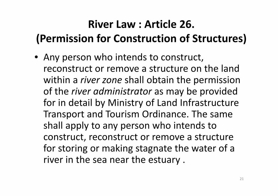
River Law : Article 26.(Permission for Construction of Structures)
h i d• Any person who intends to construct, reconstruct or remove a structure on the land within a river zone shall obtain the permission of the river administrator as may be provided for in detail by Ministry of Land Infrastructure Transport and Tourism Ordinance. The same shall apply to any person who intends to construct, reconstruct or remove a structure for storing or making stagnate the water of a river in the sea near the estuary .
21

DikeDike
• A dike is an embankment or levee constructed along the banks of a stream, river, lake or gother body of water for the purpose of protecting from overflowing floodwater byprotecting from overflowing floodwater by confining the stream flow in the regular channel River improvement should bechannel. River improvement should be planned with non‐diked river if possible to have efficient drainage conveyance.
22

RIVERSIDE LANDSIDE
Freeboard
Dike Crest ShoulderShoulderRIVER SIDE LAND SIDE
DFL Freeboard
Slope
Slope Ground LevelDike Height
S
Toe of Dike Slope
Base of DikeToe of Dike Slope
Parts of DikeParts of Dike23

1
There is a possibility that, by the force of stream during flood, the bank and river front will be scrapped and those will be collapsed.
2 Bank is stable from the friction between sand particles and water
When water% is increased, the bank becomes unstable, because the density of sand is declined. Through infiltration, sand will run out with water.
Water & Air
sand particles
During the flood, even if the water level is bellow the bank top, there is a possibility that, owing to the infiltration of river water into the bank and weakening it, then the bank will be collapsed.
3
24
Because a bank is made by earth, there is a possibility that once river flow over topped from the bank, it will scrape against the earth, then the bank will be collapsed.
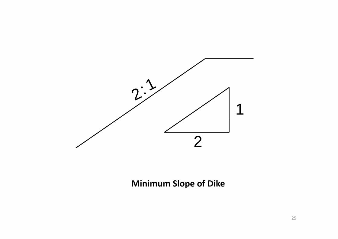
2:11
2 :
22
Minimum Slope of Dike
25

Design flood discharge Freeboard g g
Q3
(m)
(m3/s)
Less than 200 0.6
200 and up to 500 0.8
500 and up to 2 000 1 0500 and up to 2,000 1.0
2,000 and up to 5,000 1.2
5,000 and up to 10,000 1.5
10 000 and over 2 010,000 and over 2.026

Design flood discharge, Q Crest Width g g , Q(m3/sec) (m)
Less than 500 3Less than 500 3500 and up to 2,000 42 000 d t 5 000 52,000 and up to 5,000 55,000 and up to 10,000 610,000 and over 7
27

RevetmentRevetment
• Function of revetment is to protect the collapse of riverbank due to erosion, scouring p gand/or riverbed degradation.
28
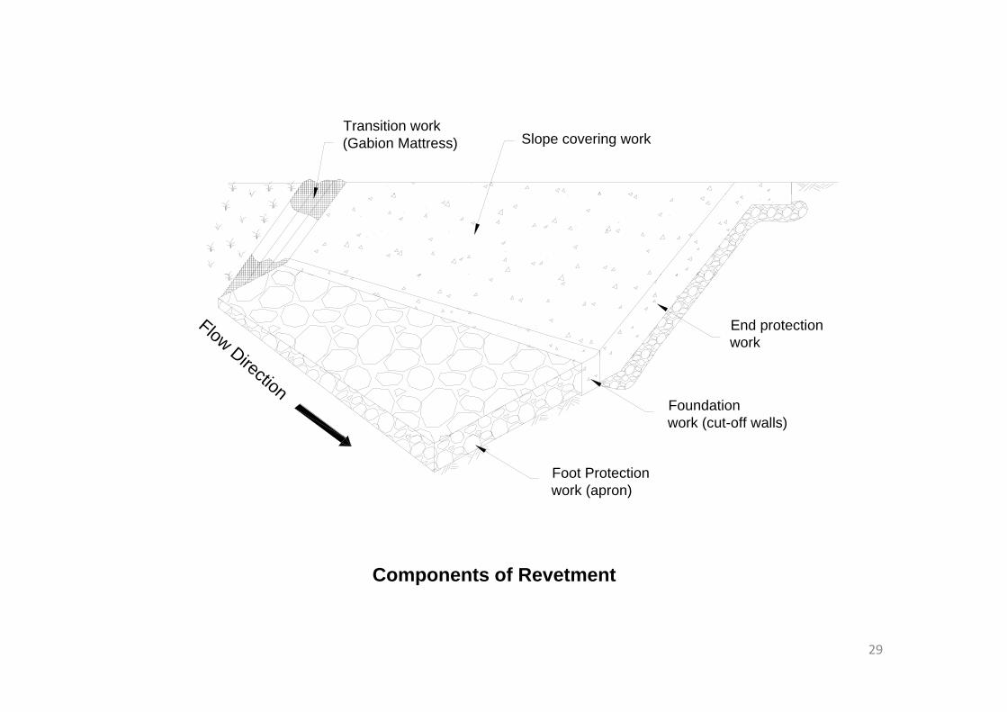
Slope covering workTransition work(Gabion Mattress)
Flow Di
End protectionworkDirection
Foundationwork (cut-off walls)
Foot Protectionwork (apron)
Components of Revetment
29

20 : 1
m0.5 : 1
Road Surface orG d S f0.
5 - 1
.0 m
Ground Surface0
Dry Stone Masonry
Toe Protection work
30

Shoulder Beam Work (Head Wall)
Foundation Work
Covering Work
Lean Concrete
Backfill Material
Foot Protection Work
Crest ProtectionWork Crest Work
Key
Crest Protection Work
Components of Revetment31

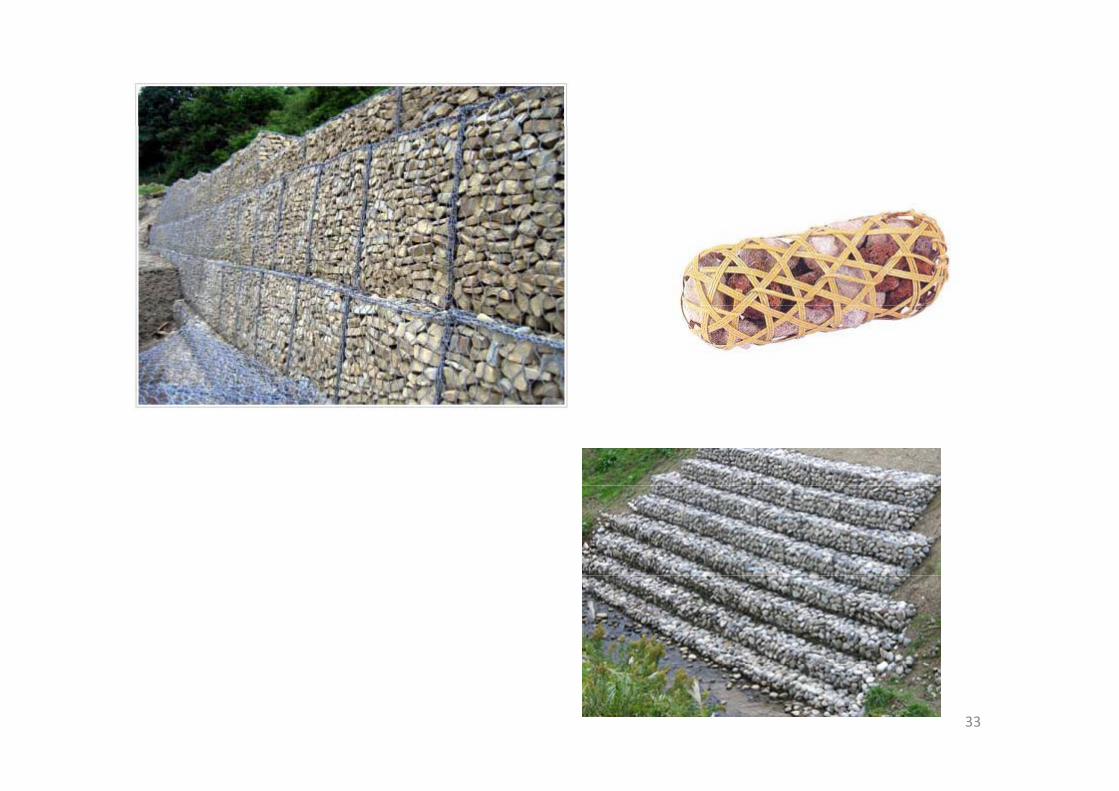
• Gabions (from Italian gabbionemeaning "big cage"; from Italian gabbia and Latin caveameaning "cage") are cages, cylinders, or boxes filled with rocks, concrete or sometimes sand and soil that are used in civil
i i d b ildi d ilit li tiengineering, road building, and military applications. For erosion control caged riprap is used. For dams or foundation construction cylindrical metal structuresfoundation construction, cylindrical metal structures are used. In a military context, earth or sand‐filled gabions are used to protect artillery crews from enemy fire.
• (From Wikipedia, the free encyclopedia)
32
33

• Riprap also known as rip rap rubble shot rock• Riprap—also known as rip rap, rubble, shot rock, rock armour or Rip‐rap—is rock or other material used to armor shorelines streambeds bridgeused to armor shorelines, streambeds, bridge abutments, pilings and other shoreline structures against scour water or ice erosionagainst scour, water or ice erosion.
• It is made from a variety of rock types, commonly granite or limestone and occasionally concretegranite or limestone, and occasionally concrete rubble from building and paving demolition. It can be used on any waterway or watercan be used on any waterway or water containment where there is potential for water erosionerosion.
• From Wikipedia, the free encyclopedia
34

35

さるすべり(百日紅): Monkey Slipping Crape
藤:wisteria
Monkey Slipping, Crape, Myrtle
藤:wisteria
36
Brake 3

The following are possible impacts resulting from the construction of a bridge:1. Water level increase upstream of the bridge due to heading‐up
for the bridge piersfor the bridge piers2. Flow velocity increase due to the bridge piers and impacts of
drift currents on leveesdrift currents on levees3. Impacts of changes in flow shear force due to the bridge piers
on river‐bed fluctuations4. Local scouring in bridge piers and river banks due to flow
velocity increase and turbulence caused by the bridge piers
37

Restrictions concerning river management for bridgeconstructionconstruction
[Mandatory restrictions]Th b id l t d th t t l h i ht f th d i fl d l l-The bridge clearance must exceed the total height of the design flood level
and the design freeboard.-The bridge must not interrupt the continuity of river management roads.
[Recommendations]-The bridge construction should avoid river sections in which the flowgregime changes, such as narrow sections, water-colliding fronts, confluences, bends, etc.
-The bridge construction should avoid river sections with frequent river-The bridge construction should avoid river sections with frequent riverbed fluctuation (points of bed-slop change).
-The bridge should be built perpendicular to the flow direction during floodingflooding.
-The bridge should not be built too close to other existing river-crossingstructures (e.g., bridges, weirs, inverted siphons, ground sills).Th b id t ti h ld id t b h i t d ld i
38
-The bridge construction should avoid past breach points and old riverchannels.

[Considerations][ ]-The bridge construction should be coordinated with surrounding land-use conditions in terms of landscapes and natural and socialenvironments (* this consideration can be considered as specific toenvironments.( this consideration can be considered as specific to some local areas)
-The bridge construction should be consistent with the basic plan for river environment managementriver environment management.
-The bridge should not have adverse impacts on other existing structures excluding river-crossing structures.
The construction of river-crossing bridges must follow the above restrictions.
Source: Manual for planning river-crossing bridge constructions(preliminary version; published in July 2009 by the Japan
Institute of Construction Engineering; JICE publication No. 109001)
39
Institute of Construction Engineering; JICE publication No. 109001)
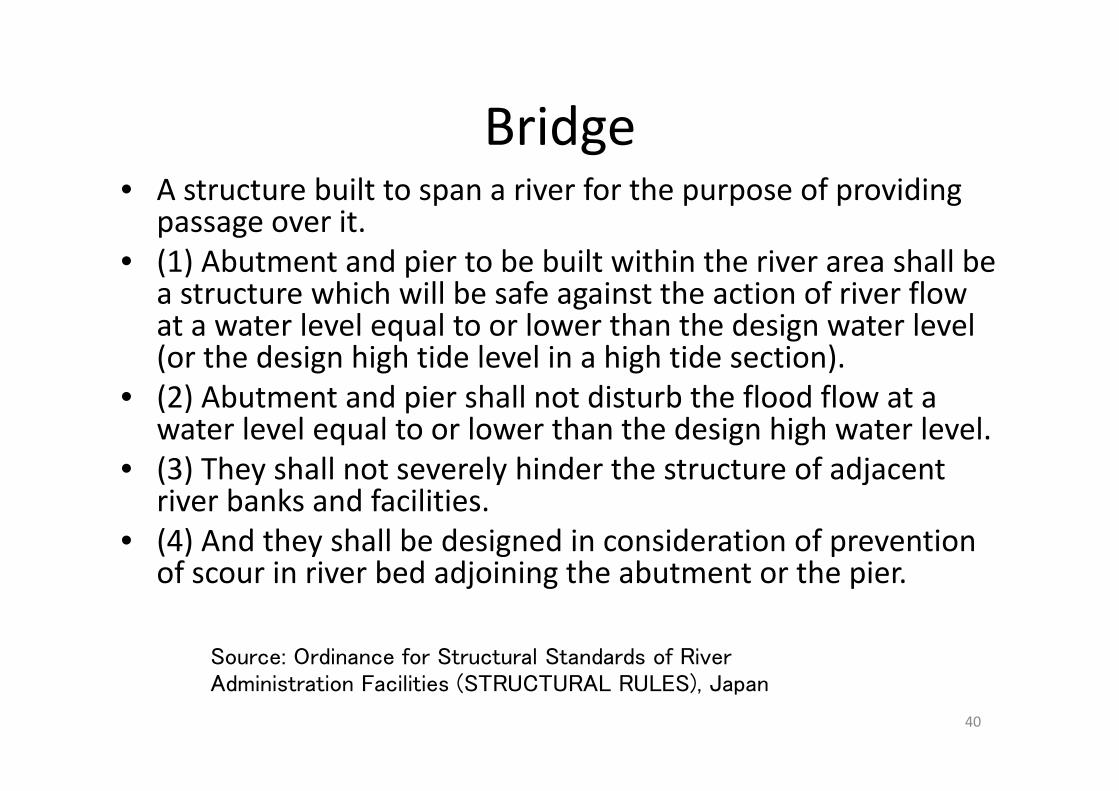
BridgeBridge• A structure built to span a river for the purpose of providing
itpassage over it.• (1) Abutment and pier to be built within the river area shall be
a structure which will be safe against the action of river flow gat a water level equal to or lower than the design water level (or the design high tide level in a high tide section).
• (2) Abutment and pier shall not disturb the flood flow at a• (2) Abutment and pier shall not disturb the flood flow at a water level equal to or lower than the design high water level.
• (3) They shall not severely hinder the structure of adjacent river banks and facilities.
• (4) And they shall be designed in consideration of prevention of scour in river bed adjoining the abutment or the pierof scour in river bed adjoining the abutment or the pier.
Source: Ordinance for Structural Standards of River
40
Administration Facilities (STRUCTURAL RULES), Japan

Abutment
FreeboardCrest Width Crest WidthFreeboard
Bank
Usually, depth ratio is 1/(18‐20). Be careful for high banking in soft
Depth
Sground Span
41
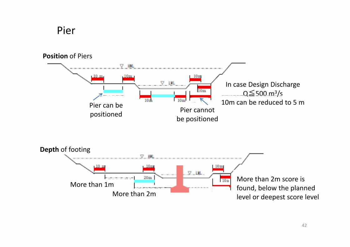
Pier
Position of Piers
In case Design Discharge Q≦500 m3/sQ≦500 m /s
10m can be reduced to 5 mPier can be positioned Pier cannot
be positioned
Depth of footingDepth of footing
More than 2m score is
More than 2mMore than 1m
More than 2m score is found, below the planned level or deepest score level
42

Disturbance Ratio of the piers of BridgeDisturbance Ratio of the piers of Bridge:The ratio of total width of the piers to the width of the river In order to minimize the disturbance of the flowriver. In order to minimize the disturbance of the flow discharge, in general, the ratio should be less than 5%.
Width of the river is the length of design high water level (DHWL) at the right angle of the flow between the banks. Width of the pier is the g g ppier width, which is right angle of the flow at the height of DHWL. In order to minimize the disturbance of the flow discharge, in general th ti h ld b l th 5% E i th t d ththe ratio should be less than 5%. Even in the worst case, under the condition of the structural safety, the ratio should be less than 6% in general bridge and 8% in Shinkansen railway bridge and Highway g g y g g yBridge.
43

L : Length between the piers or abutment (Between front of the Abutment to middle of the pier
or between middle of the piers)
To have great impact for RiverTo have great impact for River Management
YesNo
L ≧ 20 + 0.005QQ ≧ 500 m^3/sYesYes
No
L ≧20m Width of the River≧30m
L≧15L≧12 5 m
YesNo
L ≧15m L ≧12.5 m
44

In the case of WeirIn the case of Weir
Design flood discharge Span length (m)Design flood discharge
(m3/sec)
Span length (m)
L th 500 15Less than 500 15
500 and up to 2,000 20
2,000 and up to 4,000 30
4,000 and over 40
45

A bridge (including connection part) shastructure which will not hinder the strucinspection passage.
46

ヒメジョオン(姫女菀、学名 Erigeron annuus) 田 (Paddy)名: Erigeron annuus) 田 (Paddy)
47
Brake 4

48Bridge in Bangladesh

The Impact of structures within the river on flood flow.2
Jamuna Bridge in Bangladesh
Opened in June 1998.
75 chars and 70,000 inhabitants within a span of 10kms of the Bridge site10kms of the Bridge site both up and down stream
40,000 m3/s : bankful91,000 m3/s : 1 /1 O0
Main Bridge 4.8 km
East Guide Bund 3.07 km
West Guide Bund 3.26 km
49

Monthly Mean Water Level
• Construction of slope protection in stagnant
Monthly Mean Water Level
water• Trench dredged to full depth • Occurence of flow slides during construction • Most slides on Eastern part of dredged trench • Slope reduced to 1: 6 (initial design 1:3.5)• Reduced the depth from ‐18m to ‐15m p
50
From Dr. Gerrit J. Klaassenand JICA study report.
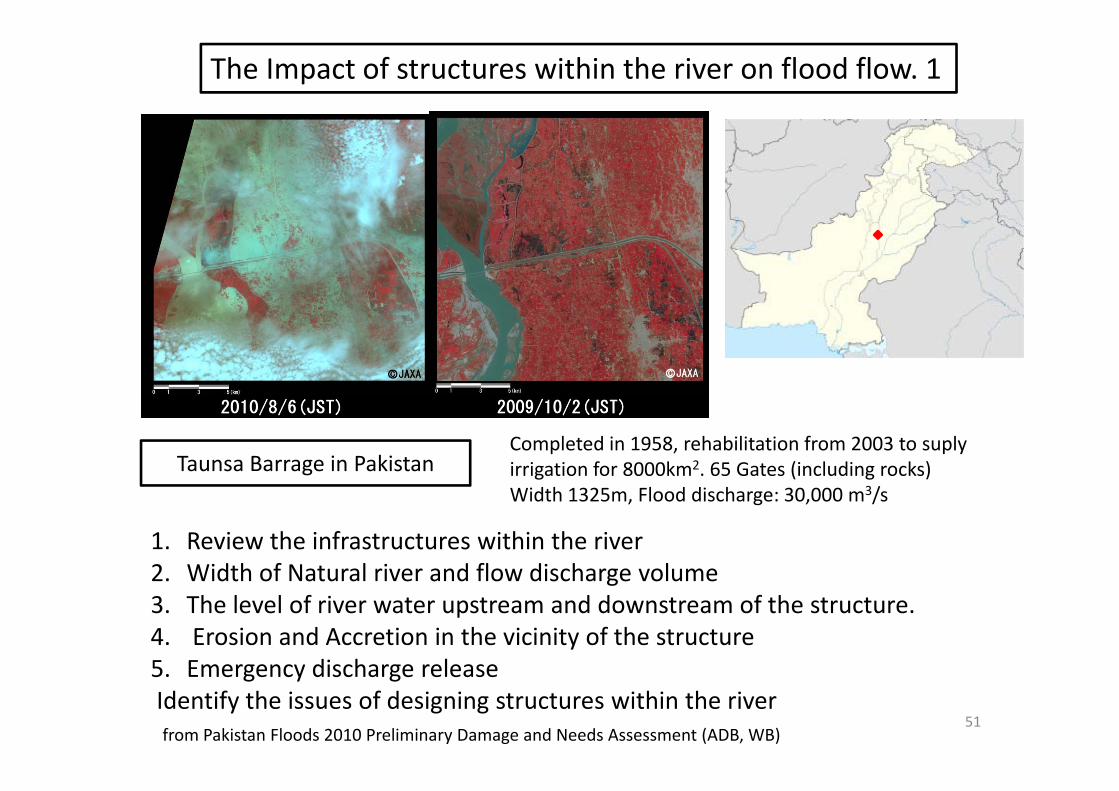
The Impact of structures within the river on flood flow. 1
Taunsa Barrage in PakistanCompleted in 1958, rehabilitation from 2003 to suplyirrigation for 8000km2. 65 Gates (including rocks) Width 1325m, Flood discharge: 30,000 m3/s
1. Review the infrastructures within the river2 Width of Natural river and flow discharge volume2. Width of Natural river and flow discharge volume3. The level of river water upstream and downstream of the structure.4. Erosion and Accretion in the vicinity of the structure5 Emergency discharge release
51
5. Emergency discharge release Identify the issues of designing structures within the river from Pakistan Floods 2010 Preliminary Damage and Needs Assessment (ADB, WB)
ReferenceReference
• Ministry of Land Infrastructure Transport and Tourism Ordinance for Structural Standards of River Administration Facilities (STRUCTURAL RULES) JapanFacilities (STRUCTURAL RULES), Japan
• Ri d D T h i l St d d J• River and Dam Technical Standards, Japan
M l f l i i i b id t ti• Manual for planning river-crossing bridge constructions(preliminary version; published in July 2009 by the Japan
Institute of Construction Engineering; JICE publication NoInstitute of Construction Engineering; JICE publication No. 109001)
52
