design cdpo akiveedu revised
DESCRIPTION
Design of CDPO OfficeTRANSCRIPT
DESIGN OF STRUCTURE
Construction of C.D.P.O.Office at Akiveedu
Est.Cost.Rs.53.00 lakhs
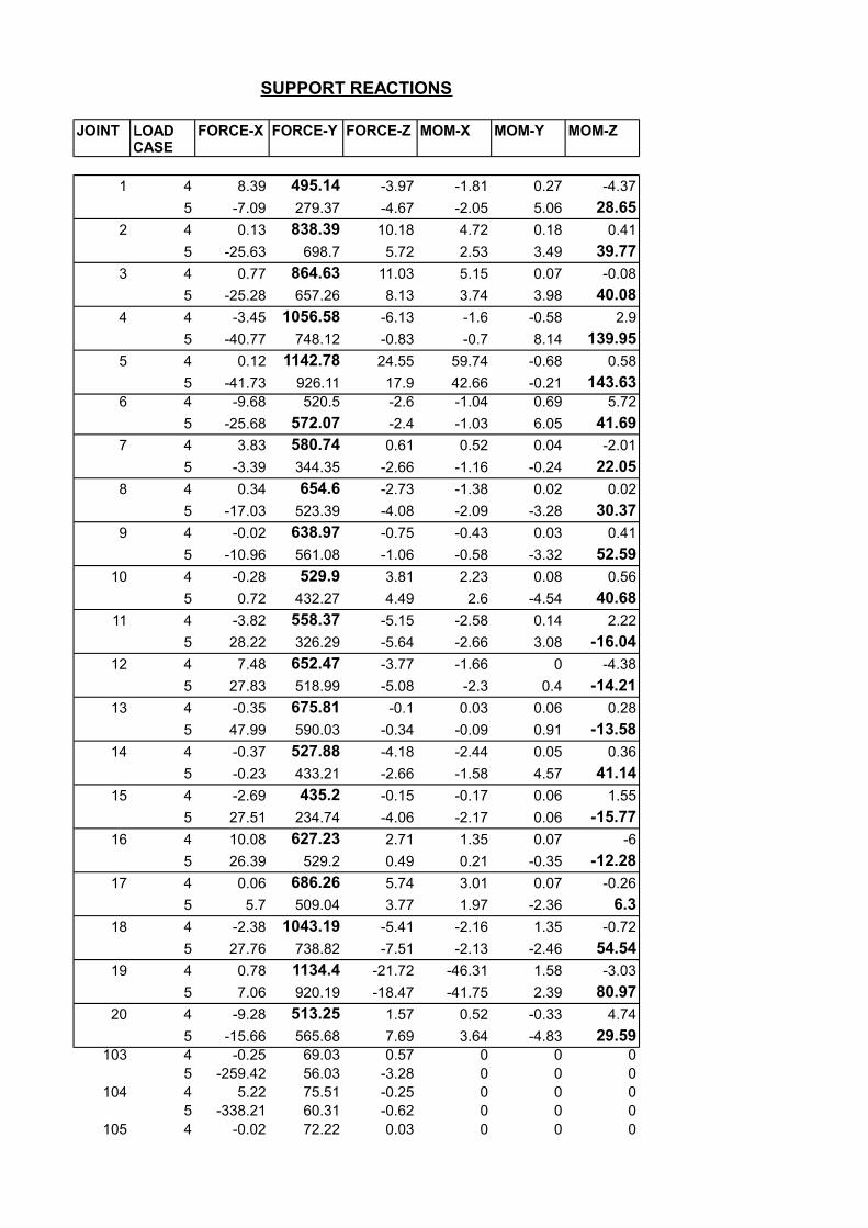
SUPPORT REACTIONS
JOINT FORCE-X FORCE-Y FORCE-Z MOM-X MOM-Y MOM-Z
1 4 8.39 495.14 -3.97 -1.81 0.27 -4.37
5 -7.09 279.37 -4.67 -2.05 5.06 28.652 4 0.13 838.39 10.18 4.72 0.18 0.41
5 -25.63 698.7 5.72 2.53 3.49 39.773 4 0.77 864.63 11.03 5.15 0.07 -0.08
5 -25.28 657.26 8.13 3.74 3.98 40.084 4 -3.45 1056.58 -6.13 -1.6 -0.58 2.9
5 -40.77 748.12 -0.83 -0.7 8.14 139.955 4 0.12 1142.78 24.55 59.74 -0.68 0.58
5 -41.73 926.11 17.9 42.66 -0.21 143.636 4 -9.68 520.5 -2.6 -1.04 0.69 5.72
5 -25.68 572.07 -2.4 -1.03 6.05 41.697 4 3.83 580.74 0.61 0.52 0.04 -2.01
5 -3.39 344.35 -2.66 -1.16 -0.24 22.058 4 0.34 654.6 -2.73 -1.38 0.02 0.02
5 -17.03 523.39 -4.08 -2.09 -3.28 30.379 4 -0.02 638.97 -0.75 -0.43 0.03 0.41
5 -10.96 561.08 -1.06 -0.58 -3.32 52.5910 4 -0.28 529.9 3.81 2.23 0.08 0.56
5 0.72 432.27 4.49 2.6 -4.54 40.6811 4 -3.82 558.37 -5.15 -2.58 0.14 2.22
5 28.22 326.29 -5.64 -2.66 3.08 -16.0412 4 7.48 652.47 -3.77 -1.66 0 -4.38
5 27.83 518.99 -5.08 -2.3 0.4 -14.2113 4 -0.35 675.81 -0.1 0.03 0.06 0.28
5 47.99 590.03 -0.34 -0.09 0.91 -13.5814 4 -0.37 527.88 -4.18 -2.44 0.05 0.36
5 -0.23 433.21 -2.66 -1.58 4.57 41.1415 4 -2.69 435.2 -0.15 -0.17 0.06 1.55
5 27.51 234.74 -4.06 -2.17 0.06 -15.7716 4 10.08 627.23 2.71 1.35 0.07 -6
5 26.39 529.2 0.49 0.21 -0.35 -12.2817 4 0.06 686.26 5.74 3.01 0.07 -0.26
5 5.7 509.04 3.77 1.97 -2.36 6.318 4 -2.38 1043.19 -5.41 -2.16 1.35 -0.72
5 27.76 738.82 -7.51 -2.13 -2.46 54.5419 4 0.78 1134.4 -21.72 -46.31 1.58 -3.03
5 7.06 920.19 -18.47 -41.75 2.39 80.9720 4 -9.28 513.25 1.57 0.52 -0.33 4.74
5 -15.66 565.68 7.69 3.64 -4.83 29.59103 4 -0.25 69.03 0.57 0 0 0
5 -259.42 56.03 -3.28 0 0 0104 4 5.22 75.51 -0.25 0 0 0
5 -338.21 60.31 -0.62 0 0 0105 4 -0.02 72.22 0.03 0 0 0
LOAD CASE
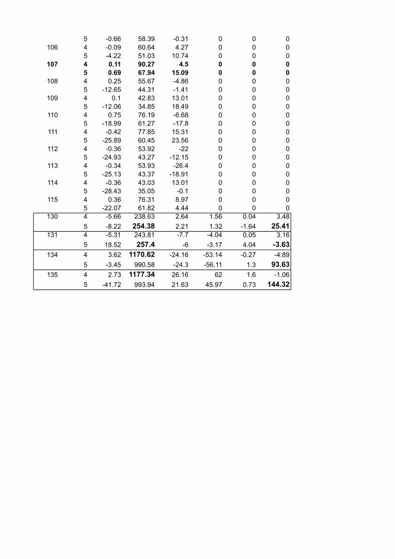
5 -0.66 58.39 -0.31 0 0 0106 4 -0.09 60.64 4.27 0 0 0
5 -4.22 51.03 10.74 0 0 0107 4 0.11 90.27 4.5 0 0 0
5 0.69 67.94 15.09 0 0 0108 4 0.25 55.67 -4.86 0 0 0
5 -12.65 44.31 -1.41 0 0 0109 4 0.1 42.83 13.01 0 0 0
5 -12.06 34.85 18.49 0 0 0110 4 0.75 76.19 -6.68 0 0 0
5 -18.99 61.27 -17.8 0 0 0111 4 -0.42 77.85 15.31 0 0 0
5 -25.89 60.45 23.56 0 0 0112 4 -0.36 53.92 -22 0 0 0
5 -24.93 43.27 -12.15 0 0 0113 4 -0.34 53.93 -26.4 0 0 0
5 -25.13 43.37 -18.91 0 0 0114 4 -0.36 43.03 13.01 0 0 0
5 -28.43 35.05 -0.1 0 0 0115 4 0.36 76.31 8.97 0 0 0
5 -22.07 61.82 4.44 0 0 0130 4 -5.66 238.63 2.64 1.56 0.04 3.48
5 -8.22 254.38 2.21 1.32 -1.64 25.41131 4 -5.31 243.81 -7.7 -4.04 0.05 3.16
5 18.52 257.4 -6 -3.17 4.04 -3.63134 4 3.62 1170.62 -24.16 -53.14 -0.27 -4.89
5 -3.45 990.58 -24.3 -56.11 1.3 93.63135 4 2.73 1177.34 26.16 62 1.6 -1.06
5 -41.72 993.94 21.63 45.97 0.73 144.32

DESIGN OF RECTANGULAR FOOTINGS(4,5,18,19,134,135) Design Parametres:-
Footing designation = F1Concrete mix M20Steel Fe415Cover to Reinforcement 50mmSafe Bearing Capacity(From soil Report)= 122.50KN/sqmUnit weight of RCC = 25.0KN/cumWidth of Column b = 0.45mDepth of Column d = 0.60mCharacteristic compressive strength of concrete = 20.00N/sqmmYield strength of steel = 415.00N/sqmm
Load calculations:-
Factored Load on the column from analysis = 1177.34KN1177.34KN
Add self weight of the footing&Weight 176.601KNof back fill (15%)
Total Load = 1353.94KN
183.75KN/sqm
Size of the footing required:-
Area of the footing required = 7.37Sqm
Provide rectangular footing of size 2.30mx3.50m,the area comes to 8.05SqmWidth = 2.30mDepth = 3.50m
The net ultimate bearing pressure acting on the footing due to direct load = 168.19KN/sqm
Design moment = 62.00KN-m
Section Modulus for the above section = 4.70cum
Soil pressure due to moment = M/Z = 13.19KN/sqm
Max.Soil pressure = 181.38KN/sqm <183.75KN/sqmHence O.K
Min.Soil pressure = 155.00KN/sqm >0Hence O.K
Hence,the design soil pressure = 181.38KN/sqm
190.68KN-m(Considering 1m width of footing)
77.60KN-m
Ultimate Bearing Capacity of the soil qu = 1.5xSBC =
(1/6)xbd2 =
pu + m
u =
pu - m
u =
The maximum bending moment at the face of the column wrt the section along width ML =
The maximum bending moment at the face of the column wrt the section along length MB =

(Considering 1m width of footing)
Depth of the footing required:-
i)Bending moment criteria:-
The critical section for bending is at the face of the column.Hence,the
190.68KN-m(Considering 1m width of footing)
The effective depth of footing required = d =
= 262.84mm
Over all depth required assuming 12mm dia bars = = 318.84mm
442.00mm
Longitudinal direction:-
Calculation of reinforcement :-
The actual depth of neutral axis = 63.78mm
Area of steel required = 1271.94sqmm
Assuming 16mm dia bars,the spacing comes to 158mm
Provide 16mm bars at a spacing of 125mm along width
Then the area of reinforcement provided = 1607.68Sqm
Percentage of reinforcement provided = 0.364
Check for one way shear:-
The critical section of one way shear is at a distance of 'd' from the face of the column
182.83KN
0.414N/sqmm <2.8 N/sqmm(As per Table 20 of 1S 456)
Hence,the section is safe from shear point of view
The percentage area of the tensile reinforcement provided = 0.364%
The design shear strength of concrete for the above steel percentage from Table 19 of IS 456 is
0.415 N/sqmm 183.43KN
Maximum factored bending moment = ML =
Adopting Limit state method of design Mu = 0.138 f
ckbd2
[Mu/(0.138f
ckb)]0.5
However assume 500mm overall depth,then the effective depth comes to
Hence,the factored design shear force VFd
=
Nominal shear stress Tv =
Hence Vuc
=

0.415 >0.414
Hence,no shear reinforcement is required.
Transverse direction:-
77.60KN-m(Considering 1m width of footing)
Over all depth provided = 500.00mm
Effective depth assuming 10mm dia bars 445.00mm
Calculation of reinforcement :-
The actual depth of neutral axis = 24.80mm
Area of steel required = 494.56sqmm
Reinforcement in central band = 0.79Total reinforcement
Reinforcement to be provided in central band = 392.24sqmm
Reinforcement to be provided in each edge band = 51.16sqmm
However provide 12mm dia bars at a spacing of 200mm along length
Then the area of reinforcement provided = 565.20Sqm
Percentage of reinforcement provided = 0.127
Check for one way shear:-
The critical section of one way shear is at a distance of 'd' from the face of the column
87.06KN
0.196N/sqmm <2.8 N/sqmm(As per Table 20 of 1S 456)
Hence,the section is safe from shear point of view
The percentage area of the tensile reinforcement provided = 0.127%
The design shear strength of concrete for the above steel percentage from Table 19 of IS 456 is
0.280 N/sqmm 124.60KN
0.280 >0.196
Maximum factored bending moment = MB =
Hence,the factored design shear force VFd
=
Nominal shear stress Tv =
Hence Vuc
=

Hence,no shear reinforcement is required.
iii)Two way shear criteria:-
The critical section for two-way shear is along the perphery of the square at adistance d/2 from the face of the column
3868mm
1291.53KN
0.76 N/sqmm
Permissible shear stress in concrete for two-way shear for M20 grade concrete
1
1.12 N/sqmm
Hence,Tc' = 1.12 N/sqmm
1.12 >0.760
Hence,the section provided is safe from two-way shear point of view
iv)Check for transfer of bearing stress:-
1353.94KN
In any case, the column face governs.Force transferred to the base through column
at the interface = 2430.00KN >1353.94KN
Hence O.K
There is no need to design separate dowel bars to tranfer the load to the base of the footing
Hence perimetre of the preriphery b0 =
Hence,the factored shear force VFd
= qu(B2-AB2)=
Nominal shear stress Tv = VFd
/b0d =
Tc' =k
s . T
c
ks = (0.5+l/b)> 1
Hence ks =
Tc = 0.25(f
ck)1/2 =
Pu =
Compressive bearing resistance = 0.45 fck
(A1/A
2)1/2.
For the column face A1/A
2 = 1 and for the other face A1/A2 > 2 but should be taken as 2.

DESIGN OF RECTANGULAR FOOTINGS(2,3) Design Parametres:-
Footing designation = F2Concrete mix M20Steel Fe415Cover to Reinforcement 50mmSafe Bearing Capacity(From soil Report)= 122.50KN/sqmUnit weight of RCC = 25.0KN/cumWidth of Column b = 0.30mDepth of Column d = 0.45mCharacteristic compressive strength of concrete = 20.00N/sqmmYield strength of steel = 415.00N/sqmm
Load calculations:-
Factored Load on the column from analysis = 864.88KN864.88KN
Add self weight of the footing&Weight 129.732KNof back fill (15%)
Total Load = 994.61KN
183.75KN/sqm
Size of the footing required:-
Area of the footing required = 5.41Sqm
Provide rectangular footing of size 2.20mx2.6m,the area comes to 5.72SqmWidth = 2.20mDepth = 2.60m
The net ultimate bearing pressure acting on the footing due to direct load = 173.88KN/sqm
Design moment = 5.150KN-m
Section Modulus for the above section = 2.48cum
Soil pressure due to moment = M/Z = 2.08KN/sqm
Max.Soil pressure = 175.96KN/sqm <183.75KN/sqmHence O.K
Min.Soil pressure = 171.80KN/sqm >0Hence O.K
Hence,the design soil pressure = 175.96KN/sqm
101.67KN-m(Considering 1m width of footing)
79.40KN-m
Ultimate Bearing Capacity of the soil qu = 1.5xSBC =
(1/6)xbd2 =
pu + m
u =
pu - m
u =
The maximum bending moment at the face of the column wrt the section along width ML =
The maximum bending moment at the face of the column wrt the section along length MB =

(Considering 1m width of footing)
Depth of the footing required:-
i)Bending moment criteria:-
The critical section for bending is at the face of the column.Hence,the
101.67KN-m(Considering 1m width of footing)
The effective depth of footing required = d =
= 191.93mm
Over all depth required assuming 12mm dia bars = = 247.93mm
394.00mm
Longitudinal direction:-
Calculation of reinforcement :-
The actual depth of neutral axis = 37.32mm
Area of steel required = 744.32sqmm
Assuming 12mm dia bars,the spacing comes to 152mm
Provide 12mm bars at a spacing of 125mm along width
Then the area of reinforcement provided = 904.32Sqm
Percentage of reinforcement provided = 0.23
Check for one way shear:-
The critical section of one way shear is at a distance of 'd' from the face of the column
119.83KN
0.304N/sqmm <2.8 N/sqmm(As per Table 20 of 1S 456)
Hence,the section is safe from shear point of view
The percentage area of the tensile reinforcement provided = 0.230%
The design shear strength of concrete for the above steel percentage from Table 19 of IS 456 is
0.344 N/sqmm 135.54KN
Maximum factored bending moment = ML =
Adopting Limit state method of design Mu = 0.138 f
ckbd2
[Mu/(0.138f
ckb)]0.5
However assume 450mm overall depth,then the effective depth comes to
Hence,the factored design shear force VFd
=
Nominal shear stress Tv =
Hence Vuc
=
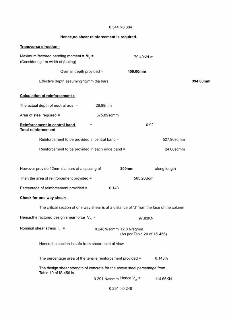
0.344 >0.304
Hence,no shear reinforcement is required.
Transverse direction:-
79.40KN-m(Considering 1m width of footing)
Over all depth provided = 450.00mm
Effective depth assuming 12mm dia bars 394.00mm
Calculation of reinforcement :-
The actual depth of neutral axis = 28.88mm
Area of steel required = 575.89sqmm
Reinforcement in central band = 0.92Total reinforcement
Reinforcement to be provided in central band = 527.90sqmm
Reinforcement to be provided in each edge band = 24.00sqmm
However provide 12mm dia bars at a spacing of 200mm along length
Then the area of reinforcement provided = 565.20Sqm
Percentage of reinforcement provided = 0.143
Check for one way shear:-
The critical section of one way shear is at a distance of 'd' from the face of the column
97.83KN
0.248N/sqmm <2.8 N/sqmm(As per Table 20 of 1S 456)
Hence,the section is safe from shear point of view
The percentage area of the tensile reinforcement provided = 0.143%
The design shear strength of concrete for the above steel percentage from Table 19 of IS 456 is
0.291 N/sqmm 114.65KN
0.291 >0.248
Maximum factored bending moment = MB =
Hence,the factored design shear force VFd
=
Nominal shear stress Tv =
Hence Vuc
=

Hence,no shear reinforcement is required.
iii)Two way shear criteria:-
The critical section for two-way shear is along the perphery of the square at adistance d/2 from the face of the column
3076mm
903.41KN
0.75 N/sqmm
Permissible shear stress in concrete for two-way shear for M20 grade concrete
1
1.12 N/sqmm
Hence,Tc' = 1.12 N/sqmm
1.12 >0.750
Hence,the section provided is safe from two-way shear point of view
iv)Check for transfer of bearing stress:-
994.61KN
In any case, the column face governs.Force transferred to the base through column
at the interface = 1215.00KN >994.61KN
Hence O.K
There is no need to design separate dowel bars to tranfer the load to the base of the footing
Hence perimetre of the preriphery b0 =
Hence,the factored shear force VFd
= qu(B2-AB2)=
Nominal shear stress Tv = VFd
/b0d =
Tc' =k
s . T
c
ks = (0.5+l/b)> 1
Hence ks =
Tc = 0.25(f
ck)1/2 =
Pu =
Compressive bearing resistance = 0.45 fck
(A1/A
2)1/2.
For the column face A1/A
2 = 1 and for the other face A1/A2 > 2 but should be taken as 2.
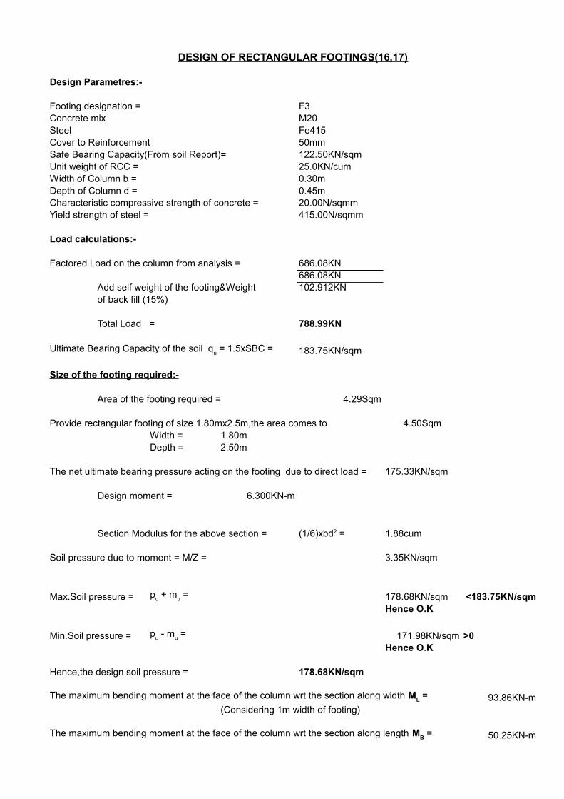
DESIGN OF RECTANGULAR FOOTINGS(16,17) Design Parametres:-
Footing designation = F3Concrete mix M20Steel Fe415Cover to Reinforcement 50mmSafe Bearing Capacity(From soil Report)= 122.50KN/sqmUnit weight of RCC = 25.0KN/cumWidth of Column b = 0.30mDepth of Column d = 0.45mCharacteristic compressive strength of concrete = 20.00N/sqmmYield strength of steel = 415.00N/sqmm
Load calculations:-
Factored Load on the column from analysis = 686.08KN686.08KN
Add self weight of the footing&Weight 102.912KNof back fill (15%)
Total Load = 788.99KN
183.75KN/sqm
Size of the footing required:-
Area of the footing required = 4.29Sqm
Provide rectangular footing of size 1.80mx2.5m,the area comes to 4.50SqmWidth = 1.80mDepth = 2.50m
The net ultimate bearing pressure acting on the footing due to direct load = 175.33KN/sqm
Design moment = 6.300KN-m
Section Modulus for the above section = 1.88cum
Soil pressure due to moment = M/Z = 3.35KN/sqm
Max.Soil pressure = 178.68KN/sqm <183.75KN/sqmHence O.K
Min.Soil pressure = 171.98KN/sqm >0Hence O.K
Hence,the design soil pressure = 178.68KN/sqm
93.86KN-m(Considering 1m width of footing)
50.25KN-m
Ultimate Bearing Capacity of the soil qu = 1.5xSBC =
(1/6)xbd2 =
pu + m
u =
pu - m
u =
The maximum bending moment at the face of the column wrt the section along width ML =
The maximum bending moment at the face of the column wrt the section along length MB =

(Considering 1m width of footing)
Depth of the footing required:-
i)Bending moment criteria:-
The critical section for bending is at the face of the column.Hence,the
93.86KN-m(Considering 1m width of footing)
The effective depth of footing required = d =
= 184.41mm
Over all depth required assuming 12mm dia bars = = 240.41mm
344.00mm
Longitudinal direction:-
Calculation of reinforcement :-
The actual depth of neutral axis = 39.83mm
Area of steel required = 794.34sqmm
Assuming 12mm dia bars,the spacing comes to 142mm
Provide 12mm bars at a spacing of 125mm along width
Then the area of reinforcement provided = 904.32Sqm
Percentage of reinforcement provided = 0.263
Check for one way shear:-
The critical section of one way shear is at a distance of 'd' from the face of the column
121.68KN
0.354N/sqmm <2.8 N/sqmm(As per Table 20 of 1S 456)
Hence,the section is safe from shear point of view
The percentage area of the tensile reinforcement provided = 0.263%
The design shear strength of concrete for the above steel percentage from Table 19 of IS 456 is
0.366 N/sqmm 125.90KN
Maximum factored bending moment = ML =
Adopting Limit state method of design Mu = 0.138 f
ckbd2
[Mu/(0.138f
ckb)]0.5
However assume 400mm overall depth,then the effective depth comes to
Hence,the factored design shear force VFd
=
Nominal shear stress Tv =
Hence Vuc
=

0.366 >0.354
Hence,no shear reinforcement is required.
Transverse direction:-
50.25KN-m(Considering 1m width of footing)
Over all depth provided = 400.00mm
Effective depth assuming 12mm dia bars 344.00mm
Calculation of reinforcement :-
The actual depth of neutral axis = 20.82mm
Area of steel required = 415.14sqmm
Reinforcement in central band = 0.84Total reinforcement
Reinforcement to be provided in central band = 347.56sqmm
Reinforcement to be provided in each edge band = 33.79sqmm
However provide 12mm dia bars at a spacing of 200mm along length
Then the area of reinforcement provided = 565.20Sqm
Percentage of reinforcement provided = 0.164
Check for one way shear:-
The critical section of one way shear is at a distance of 'd' from the face of the column
72.54KN
0.211N/sqmm <2.8 N/sqmm(As per Table 20 of 1S 456)
Hence,the section is safe from shear point of view
The percentage area of the tensile reinforcement provided = 0.164%
The design shear strength of concrete for the above steel percentage from Table 19 of IS 456 is
0.291 N/sqmm 100.10KN
0.291 >0.211
Maximum factored bending moment = MB =
Hence,the factored design shear force VFd
=
Nominal shear stress Tv =
Hence Vuc
=
Hence,no shear reinforcement is required.
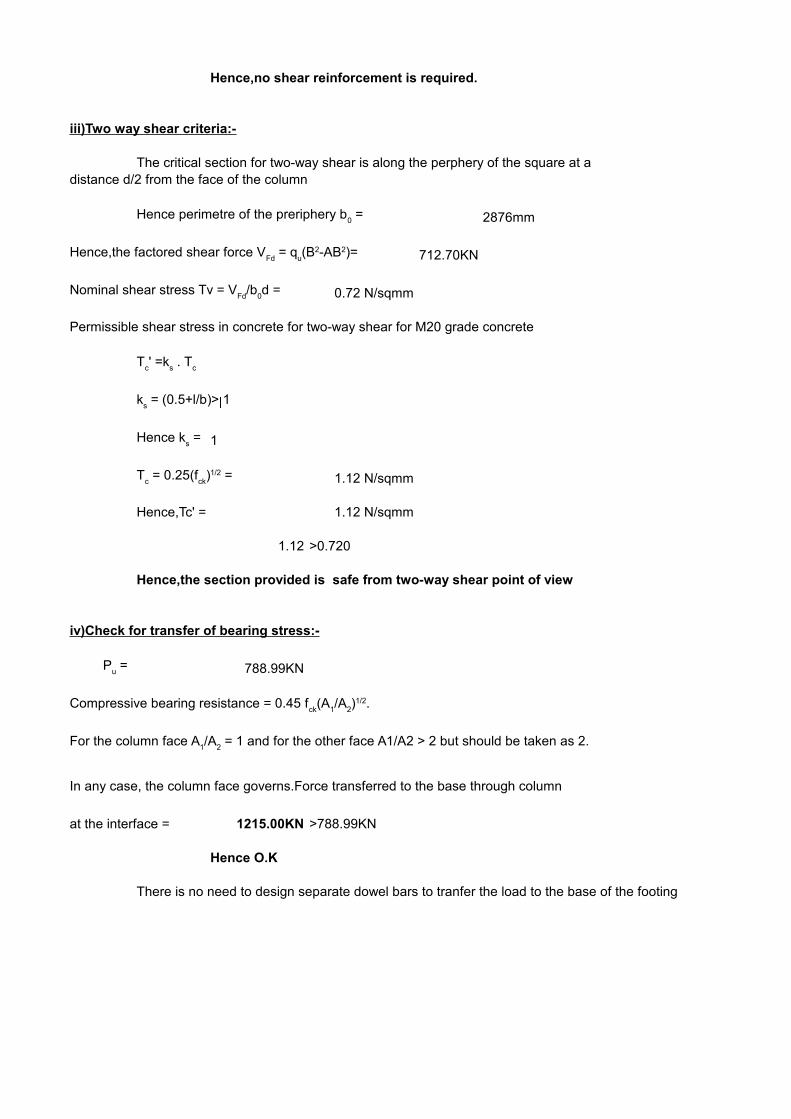
iii)Two way shear criteria:-
The critical section for two-way shear is along the perphery of the square at adistance d/2 from the face of the column
2876mm
712.70KN
0.72 N/sqmm
Permissible shear stress in concrete for two-way shear for M20 grade concrete
1
1.12 N/sqmm
Hence,Tc' = 1.12 N/sqmm
1.12 >0.720
Hence,the section provided is safe from two-way shear point of view
iv)Check for transfer of bearing stress:-
788.99KN
In any case, the column face governs.Force transferred to the base through column
at the interface = 1215.00KN >788.99KN
Hence O.K
There is no need to design separate dowel bars to tranfer the load to the base of the footing
Hence perimetre of the preriphery b0 =
Hence,the factored shear force VFd
= qu(B2-AB2)=
Nominal shear stress Tv = VFd
/b0d =
Tc' =k
s . T
c
ks = (0.5+l/b)> 1
Hence ks =
Tc = 0.25(f
ck)1/2 =
Pu =
Compressive bearing resistance = 0.45 fck
(A1/A
2)1/2.
For the column face A1/A
2 = 1 and for the other face A1/A2 > 2 but should be taken as 2.

DESIGN OF RECTANGULAR FOOTINGS(1,6,7,10,11,14,15,16,17,20) Design Parametres:-
Footing designation = F4Concrete mix M20Steel Fe415Cover to Reinforcement 50mmSafe Bearing Capacity(From soil Report)= 122.50KN/sqmUnit weight of RCC = 25.0KN/cumWidth of Column b = 0.30mDepth of Column d = 0.45mCharacteristic compressive strength of concrete = 20.00N/sqmmYield strength of steel = 415.00N/sqmm
Load calculations:-
Factored Load on the column from analysis = 572.07KN572.07KN
Add self weight of the footing&Weight 57.207KNof back fill (10%)
Total Load = 629.28KN
183.75KN/sqm
Size of the footing required:-
Area of the footing required = 3.42Sqm
Provide rectangular footing of size 1.80mx2.3m,the area comes to 4.14SqmWidth = 1.80mDepth = 2.30m
The net ultimate bearing pressure acting on the footing due to direct load = 152.00KN/sqm
Design moment = 41.690KN-m
Section Modulus for the above section = 1.59cum
Soil pressure due to moment = M/Z = 26.22KN/sqm
Max.Soil pressure = 178.22KN/sqm <183.75KN/sqmHence O.K
Min.Soil pressure = 125.78KN/sqm >0Hence O.K
Hence,the design soil pressure = 178.22KN/sqm
76.24KN-m(Considering 1m width of footing)
50.12KN-m
Ultimate Bearing Capacity of the soil qu = 1.5xSBC =
(1/6)xbd2 =
pu + m
u =
pu - m
u =
The maximum bending moment at the face of the column wrt the section along width ML =
The maximum bending moment at the face of the column wrt the section along length MB =
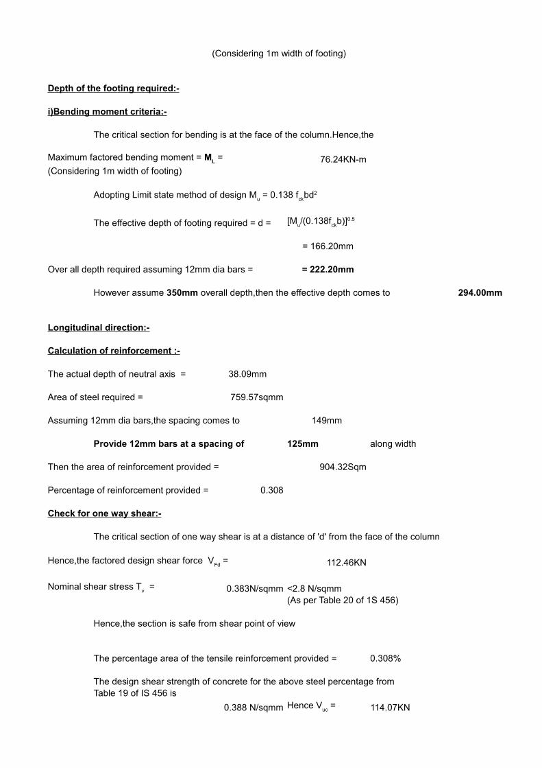
(Considering 1m width of footing)
Depth of the footing required:-
i)Bending moment criteria:-
The critical section for bending is at the face of the column.Hence,the
76.24KN-m(Considering 1m width of footing)
The effective depth of footing required = d =
= 166.20mm
Over all depth required assuming 12mm dia bars = = 222.20mm
294.00mm
Longitudinal direction:-
Calculation of reinforcement :-
The actual depth of neutral axis = 38.09mm
Area of steel required = 759.57sqmm
Assuming 12mm dia bars,the spacing comes to 149mm
Provide 12mm bars at a spacing of 125mm along width
Then the area of reinforcement provided = 904.32Sqm
Percentage of reinforcement provided = 0.308
Check for one way shear:-
The critical section of one way shear is at a distance of 'd' from the face of the column
112.46KN
0.383N/sqmm <2.8 N/sqmm(As per Table 20 of 1S 456)
Hence,the section is safe from shear point of view
The percentage area of the tensile reinforcement provided = 0.308%
The design shear strength of concrete for the above steel percentage from Table 19 of IS 456 is
0.388 N/sqmm 114.07KN
Maximum factored bending moment = ML =
Adopting Limit state method of design Mu = 0.138 f
ckbd2
[Mu/(0.138f
ckb)]0.5
However assume 350mm overall depth,then the effective depth comes to
Hence,the factored design shear force VFd
=
Nominal shear stress Tv =
Hence Vuc
=
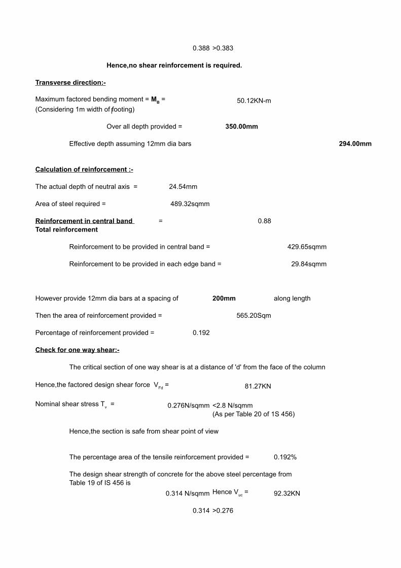
0.388 >0.383
Hence,no shear reinforcement is required.
Transverse direction:-
50.12KN-m(Considering 1m width of footing)
Over all depth provided = 350.00mm
Effective depth assuming 12mm dia bars 294.00mm
Calculation of reinforcement :-
The actual depth of neutral axis = 24.54mm
Area of steel required = 489.32sqmm
Reinforcement in central band = 0.88Total reinforcement
Reinforcement to be provided in central band = 429.65sqmm
Reinforcement to be provided in each edge band = 29.84sqmm
However provide 12mm dia bars at a spacing of 200mm along length
Then the area of reinforcement provided = 565.20Sqm
Percentage of reinforcement provided = 0.192
Check for one way shear:-
The critical section of one way shear is at a distance of 'd' from the face of the column
81.27KN
0.276N/sqmm <2.8 N/sqmm(As per Table 20 of 1S 456)
Hence,the section is safe from shear point of view
The percentage area of the tensile reinforcement provided = 0.192%
The design shear strength of concrete for the above steel percentage from Table 19 of IS 456 is
0.314 N/sqmm 92.32KN
0.314 >0.276
Maximum factored bending moment = MB =
Hence,the factored design shear force VFd
=
Nominal shear stress Tv =
Hence Vuc
=

Hence,no shear reinforcement is required.
iii)Two way shear criteria:-
The critical section for two-way shear is along the perphery of the square at adistance d/2 from the face of the column
2676mm
659.07KN
0.84 N/sqmm
Permissible shear stress in concrete for two-way shear for M20 grade concrete
1
1.12 N/sqmm
Hence,Tc' = 1.12 N/sqmm
1.12 >0.840
Hence,the section provided is safe from two-way shear point of view
iv)Check for transfer of bearing stress:-
629.28KN
In any case, the column face governs.Force transferred to the base through column
at the interface = 1215.00KN >629.28KN
Hence O.K
There is no need to design separate dowel bars to tranfer the load to the base of the footing
Hence perimetre of the preriphery b0 =
Hence,the factored shear force VFd
= qu(B2-AB2)=
Nominal shear stress Tv = VFd
/b0d =
Tc' =k
s . T
c
ks = (0.5+l/b)> 1
Hence ks =
Tc = 0.25(f
ck)1/2 =
Pu =
Compressive bearing resistance = 0.45 fck
(A1/A
2)1/2.
For the column face A1/A
2 = 1 and for the other face A1/A2 > 2 but should be taken as 2.


6 25 2946.4298 25 3928.571 12 16 2413.714
14 16 2816
6 20 1885.714

16 12 1810.286


DESIGN OF FOOTINGS(130,131) Design Parametres:-
Footing designation = F5Concrete mix M20Steel Fe415Cover to Reinforcement 50mmSafe Bearing Capacity(From soil Report)= 122.50KN/sqmUnit weight of RCC = 25.0KN/cumWidth of Column b = 0.23mDepth of Column d = 0.30mCharacteristic compressive strength of concrete = 20.00N/sqmmYield strength of steel = 415.00N/sqmm
Load calculations:-
Factored Load on the column from analysis = 257.40KN257.40KN
Add self weight of the footing&Weight 38.610KNof back fill (15%)
Total Load = 296.01KN
183.75KN/sqm
Size of the footing required:-
Area of the footing required = 1.61Sqm
Provide square footing of size 1.50mx1.50m,the area comes to 2.25SqmWidth = 1.50mDepth = 1.50m
The net ultimate bearing pressure acting on the footing due to direct load = 131.56KN/sqm
Design moment = 25.41KN-m
Section Modulus for the above section = 0.56cum
Soil pressure due to moment = M/Z = 45.38KN/sqm
Max.Soil pressure = 176.94KN/sqm <183.75KN/sqmHence O.K
Min.Soil pressure = 86.19KN/sqm >0Hence O.K
Hence,the design soil pressure = 176.94KN/sqm
Depth of the footing required:-
i)Bending moment criteria:-
The critical section for bending is at the face of the column.Hence,the
Ultimate Bearing Capacity of the soil qu = 1.5xSBC =
(1/6)xbd2 =
pu + m
u =
pu - m
u =
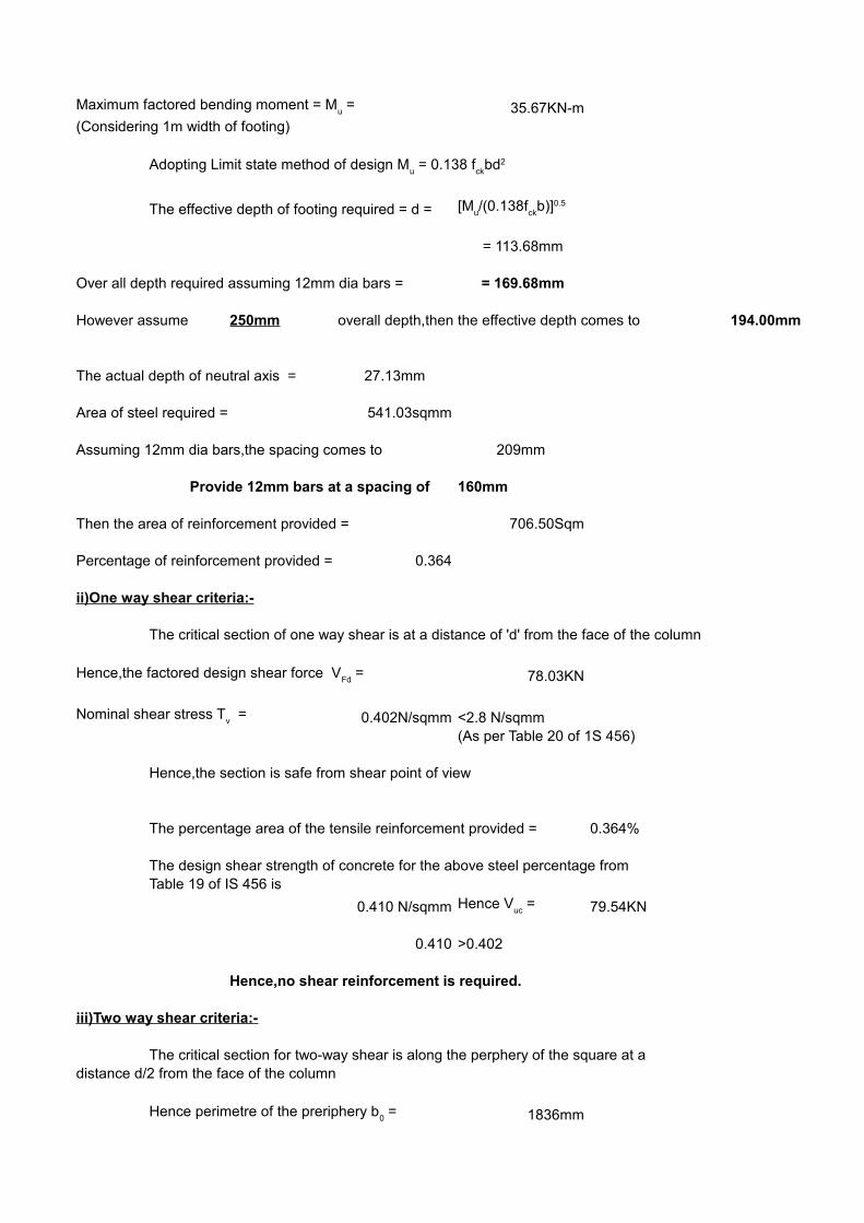
35.67KN-m(Considering 1m width of footing)
The effective depth of footing required = d =
= 113.68mm
Over all depth required assuming 12mm dia bars = = 169.68mm
However assume 250mm overall depth,then the effective depth comes to 194.00mm
The actual depth of neutral axis = 27.13mm
Area of steel required = 541.03sqmm
Assuming 12mm dia bars,the spacing comes to 209mm
Provide 12mm bars at a spacing of 160mm
Then the area of reinforcement provided = 706.50Sqm
Percentage of reinforcement provided = 0.364
ii)One way shear criteria:-
The critical section of one way shear is at a distance of 'd' from the face of the column
78.03KN
0.402N/sqmm <2.8 N/sqmm(As per Table 20 of 1S 456)
Hence,the section is safe from shear point of view
The percentage area of the tensile reinforcement provided = 0.364%
The design shear strength of concrete for the above steel percentage from Table 19 of IS 456 is
0.410 N/sqmm 79.54KN
0.410 >0.402
Hence,no shear reinforcement is required.
iii)Two way shear criteria:-
The critical section for two-way shear is along the perphery of the square at adistance d/2 from the face of the column
1836mm
Maximum factored bending moment = Mu =
Adopting Limit state method of design Mu = 0.138 f
ckbd2
[Mu/(0.138f
ckb)]0.5
Hence,the factored design shear force VFd
=
Nominal shear stress Tv =
Hence Vuc
=
Hence perimetre of the preriphery b0 =
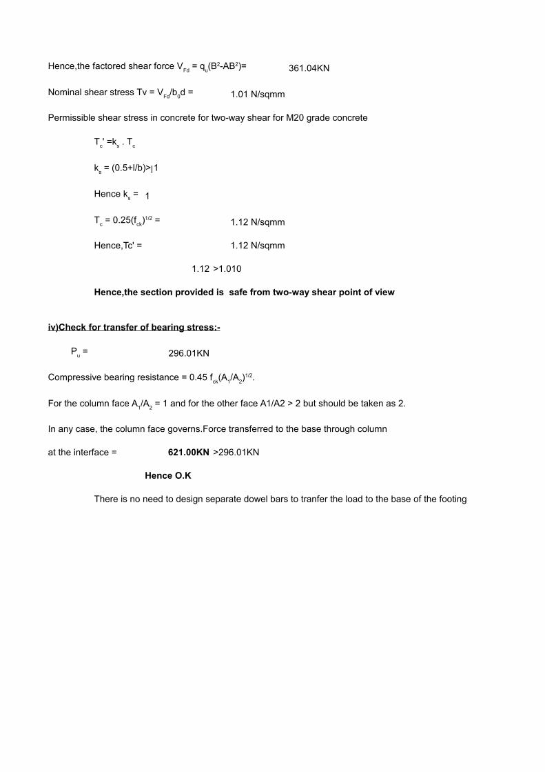
361.04KN
1.01 N/sqmm
Permissible shear stress in concrete for two-way shear for M20 grade concrete
1
1.12 N/sqmm
Hence,Tc' = 1.12 N/sqmm
1.12 >1.010
Hence,the section provided is safe from two-way shear point of view
iv)Check for transfer of bearing stress:-
296.01KN
In any case, the column face governs.Force transferred to the base through column
at the interface = 621.00KN >296.01KN
Hence O.K
There is no need to design separate dowel bars to tranfer the load to the base of the footing
Hence,the factored shear force VFd
= qu(B2-AB2)=
Nominal shear stress Tv = VFd
/b0d =
Tc' =k
s . T
c
ks = (0.5+l/b)> 1
Hence ks =
Tc = 0.25(f
ck)1/2 =
Pu =
Compressive bearing resistance = 0.45 fck
(A1/A
2)1/2.
For the column face A1/A
2 = 1 and for the other face A1/A2 > 2 but should be taken as 2.
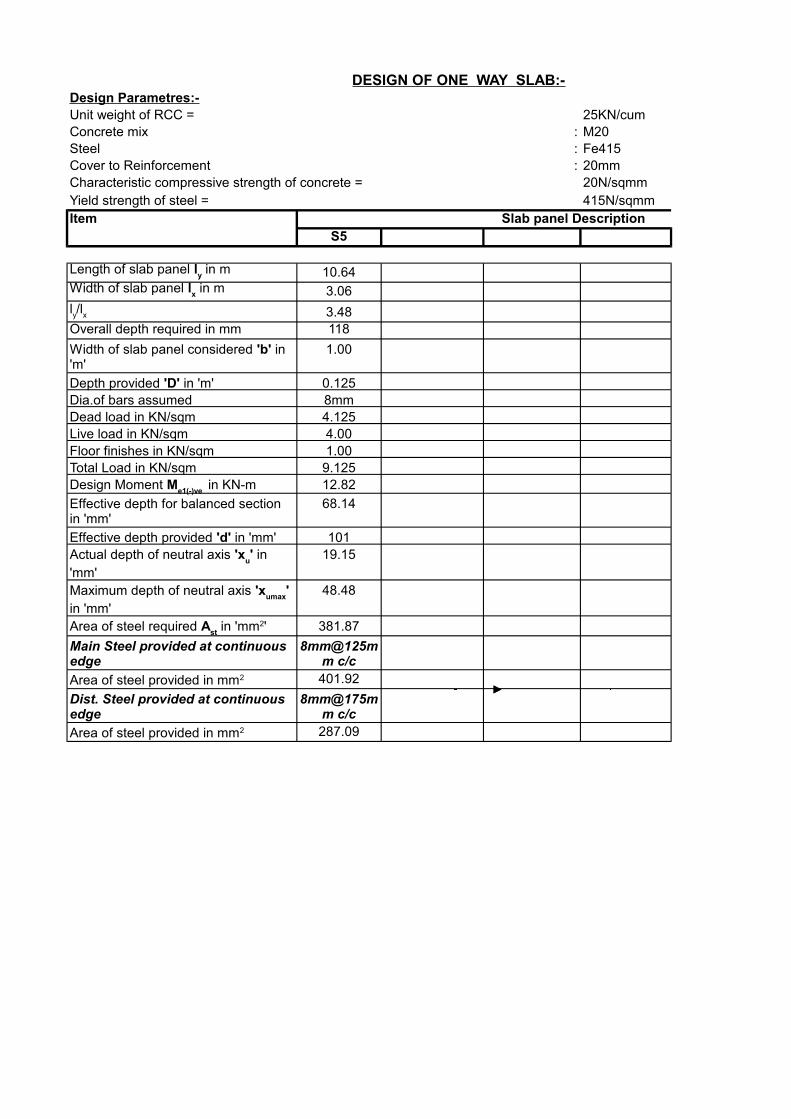
DESIGN OF ONE WAY SLAB:-Design Parametres:-Unit weight of RCC = 25KN/cumConcrete mix : M20Steel : Fe415Cover to Reinforcement : 20mmCharacteristic compressive strength of concrete = 20N/sqmmYield strength of steel = 415N/sqmmItem Slab panel Description
S5
10.64
3.06
3.48Overall depth required in mm 118
1.00
0.125Dia.of bars assumed 8mmDead load in KN/sqm 4.125Live load in KN/sqm 4.00Floor finishes in KN/sqm 1.00Total Load in KN/sqm 9.125
12.82
68.14
10119.15
48.48
381.87
401.92
287.09
Length of slab panel ly in m
Width of slab panel lx in m
ly/l
x
Width of slab panel considered 'b' in 'm'
Depth provided 'D' in 'm'
Design Moment Me1(-)ve
in KN-m
Effective depth for balanced section in 'mm'
Effective depth provided 'd' in 'mm'Actual depth of neutral axis 'x
u' in
'mm'Maximum depth of neutral axis 'x
umax'
in 'mm'Area of steel required A
st in 'mm2'
Main Steel provided at continuous edge
8mm@125mm c/c
Area of steel provided in mm2
Dist. Steel provided at continuous edge
8mm@175mm c/c
Area of steel provided in mm2
DESIGN OF ONE WAY SLAB:-
Slab panel Description
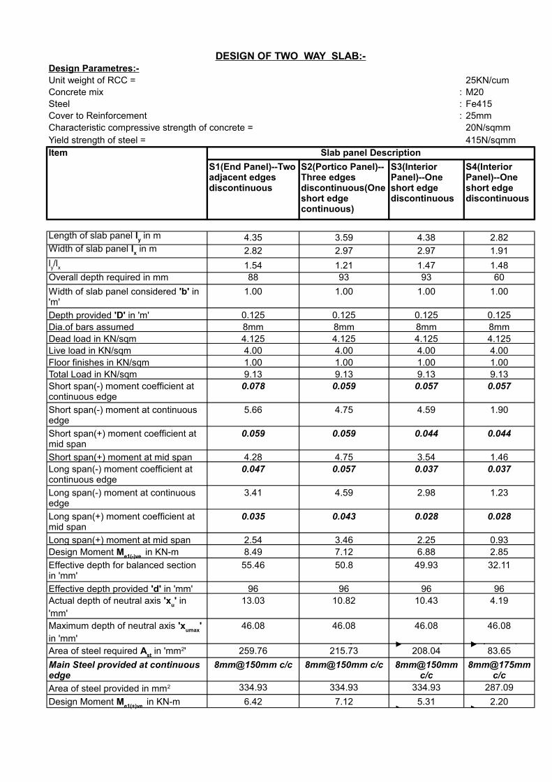
DESIGN OF TWO WAY SLAB:-Design Parametres:-Unit weight of RCC = 25KN/cumConcrete mix : M20Steel : Fe415Cover to Reinforcement : 25mmCharacteristic compressive strength of concrete = 20N/sqmmYield strength of steel = 415N/sqmmItem Slab panel Description
4.35 3.59 4.38 2.82
2.82 2.97 2.97 1.91
1.54 1.21 1.47 1.48Overall depth required in mm 88 93 93 60
1.00 1.00 1.00 1.00
0.125 0.125 0.125 0.125Dia.of bars assumed 8mm 8mm 8mm 8mmDead load in KN/sqm 4.125 4.125 4.125 4.125Live load in KN/sqm 4.00 4.00 4.00 4.00Floor finishes in KN/sqm 1.00 1.00 1.00 1.00Total Load in KN/sqm 9.13 9.13 9.13 9.13
0.078 0.059 0.057 0.057
5.66 4.75 4.59 1.90
0.059 0.059 0.044 0.044
Short span(+) moment at mid span 4.28 4.75 3.54 1.460.047 0.057 0.037 0.037
3.41 4.59 2.98 1.23
0.035 0.043 0.028 0.028
Long span(+) moment at mid span 2.54 3.46 2.25 0.938.49 7.12 6.88 2.85
55.46 50.8 49.93 32.11
96 96 96 9613.03 10.82 10.43 4.19
46.08 46.08 46.08 46.08
259.76 215.73 208.04 83.65
8mm@150mm c/c 8mm@150mm c/c
334.93 334.93 334.93 287.09
6.42 7.12 5.31 2.20
S1(End Panel)--Two adjacent edges discontinuous
S2(Portico Panel)--Three edges discontinuous(One short edge continuous)
S3(Interior Panel)--One short edge discontinuous
S4(Interior Panel)--One short edge discontinuous
Length of slab panel ly in m
Width of slab panel lx in m
ly/l
x
Width of slab panel considered 'b' in 'm'
Depth provided 'D' in 'm'
Short span(-) moment coefficient at continuous edge
Short span(-) moment at continuous edge
Short span(+) moment coefficient at mid span
Long span(-) moment coefficient at continuous edge
Long span(-) moment at continuous edge
Long span(+) moment coefficient at mid span
Design Moment Me1(-)ve
in KN-m
Effective depth for balanced section in 'mm'
Effective depth provided 'd' in 'mm'Actual depth of neutral axis 'x
u' in
'mm'Maximum depth of neutral axis 'x
umax'
in 'mm'Area of steel required A
st in 'mm2'
Main Steel provided at continuous edge
8mm@150mm c/c
8mm@175mm c/c
Area of steel provided in mm2
Design Moment Me1(+)ve
in KN-m
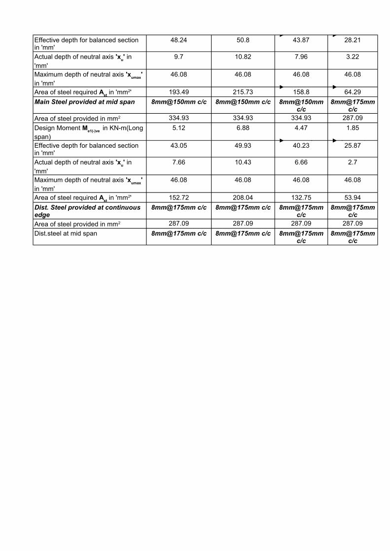
48.24 50.8 43.87 28.21
9.7 10.82 7.96 3.22
46.08 46.08 46.08 46.08
193.49 215.73 158.8 64.29
Main Steel provided at mid span 8mm@150mm c/c 8mm@150mm c/c
334.93 334.93 334.93 287.09
5.12 6.88 4.47 1.85
43.05 49.93 40.23 25.87
7.66 10.43 6.66 2.7
46.08 46.08 46.08 46.08
152.72 208.04 132.75 53.94
8mm@175mm c/c 8mm@175mm c/c
287.09 287.09 287.09 287.09
Dist.steel at mid span 8mm@175mm c/c 8mm@175mm c/c
Effective depth for balanced section in 'mm'
Actual depth of neutral axis 'xu' in
'mm'Maximum depth of neutral axis 'x
umax'
in 'mm'Area of steel required A
st in 'mm2'
8mm@150mm c/c
8mm@175mm c/c
Area of steel provided in mm2
Design Moment Me1(-)ve
in KN-m(Long span)Effective depth for balanced section in 'mm'
Actual depth of neutral axis 'xu' in
'mm'Maximum depth of neutral axis 'x
umax'
in 'mm'Area of steel required A
st in 'mm2'
Dist. Steel provided at continuous edge
8mm@175mm c/c
8mm@175mm c/c
Area of steel provided in mm2
8mm@175mm c/c
8mm@175mm c/c