design assisted by wind tunnel testing: … · design assisted by wind tunnel testing: examples...
TRANSCRIPT

DESIGN ASSISTED BY WIND TUNNEL TESTING: EXAMPLES
Massimo Majowiecki Professor
IUAV University Venice, Italy
E-mail: [email protected]
ABSTRACT According to principle of the “design assisted by testing”, contemplated by the Eurocode, the combination of tests and calculations is increasingly used. The motivation of this increasing interest-demand are various: from the sophisticated architectural shapes to the absence of corresponding reliable fluid-dynamics models, from the increasing flexibility of structures to the necessity of checking complex aeroelastic phenomena. The purpose of the paper is to outline the potentiality of wind tunnel testing and the main problems encountered in their use. These aspects have to be accurately evaluated in defining the tests specifications. The use of some data analysis techniques (such as the proper orthogonal decomposition, the sensibility analysis, etc.), in keeping the essential design parameters, is presented too. The cited tasks are presented by referring to some of the recent experiences, made by the Author within the design stage of steel structures: a cable stayed bridge on the Adige river (on the A31 motorway - Italy); the New Braga Stadium (Braga - Portugal); the new Unipol headquarter Tower (Bologna - Italy); the tall building and the roof on “Piazza delle Città Lombarde” (Milan - Italy); the new Bologna town-hall (Bologna - Italy). 1. INTRODUCTION The paper presents some of the recent experiences in wind tunnel testing, made by the Author within the design stage of steel structures. According to principle of the “design assisted by testing”, contemplated by the Eurocode, the combination of tests and calculations is increasingly used. Multiples are the motivation of this increasing interest/demand. The sophisticated architectural shapes (culminating in the “free form design”), the absence of corresponding reliable fluid-dynamics models and the increasing flexibility of structures are probably the main ones. Not less important is the opportunity/necessity to confirm by control checks the assumptions made in the design, specially with respect to complex aeroelastic phenomena, such as the lock-in, the flutter, the rain-wind induced vibration, etc.. The main purpose of the paper is to outline the potentiality of the presented tests and the main problems encountered in their use. These aspects have to be accurately evaluated in defining the tests specifications. The use of some data analysis techniques (such as the proper orthogonal decomposition, the sensibility analysis, etc.), in keeping the essential design parameters, is presented too.

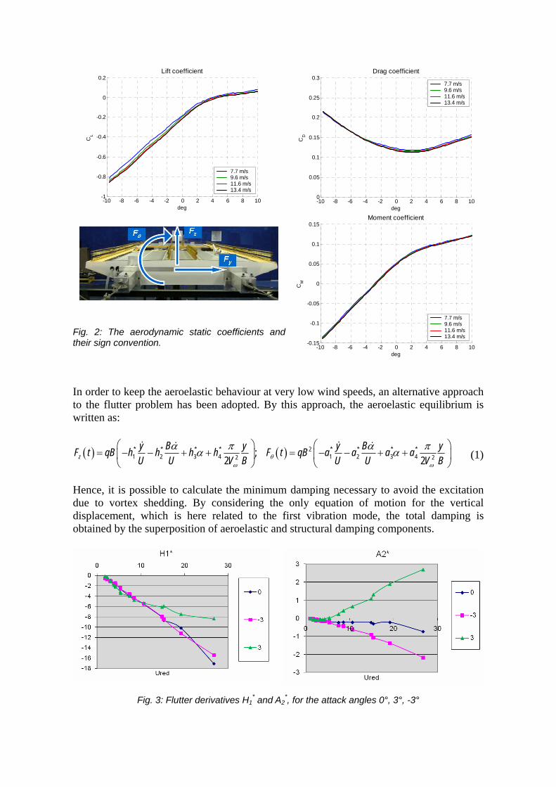
Fig. 1: Experimental deck model and deck section (Adige River Bridge) The presented experiences are relative to the tests performed during the design of: a cable stayed bridge on the Adige river (on the A31 motorway - Italy); the New Braga Stadium (Braga - Portugal); the new Unipol headquarter Tower (Bologna - Italy); the tall building and the roof on “Piazza delle Città Lombarde” (Milan - Italy); the new Bologna town-hall (Bologna - Italy). 2. THE ADIGE RIVER BRIDGE The design of the Adige river cable stayed bridge was assisted by wind tunnel tests aimed to check the aerodynamic and the aeroelastic behaviour of the deck and of the tower. The tests were carried out at the “Politecnico di Milano” boundary layer wind tunnel (Fig. 1). Regarding the bridge deck, the aerodynamic static coefficients, the classical flutter derivatives and the flutter derivatives at low reduced velocity were measured. The model of the deck was an elastic model made by an aluminium structure. Since the (expected) ratio between the flexural and the torsional frequencies was quite close to the unity (0.85) the coupled flutter was afraid and, hence, this ratio was reproduced at the model scale. The quasi-static aerodynamic forces were measured in low turbulence conditions, at different angle of attack. The aerodynamic coefficients (Fig. 2) allow to determine the quasi-static wind forces on the deck and to check the galloping sensitivity. The aeroelastic behaviour was investigated by both a direct and an inverse method. The direct method consists in measuring the wind induced forces on the deck under an externally imposed 1-DOF motion. This allows to define and change a-priori the (mean) angle of attack; it also allows a large reproducibility of the tests. On the other hand, the inverse method consist in measuring the forces on the duck during a free motion. This procedure allows to investigate the vortex shedding mechanism. Based on the wind tunnel measured aeroelastic derivatives (Fig. 3), the flutter critical conditions (velocity and frequency) have been investigated by mean of the classical Scanlan-Tomko procedure (Fig. 4). The order of magnitudes have been check by comparing the results with those obtained by the simplified Theodorsen theory. The influence of the angle of attack and of the inherent structural damping on the critical parameters has been checked too.
-10 -8 -6 -4 -2 0 2 4 6 8 10-1
-0.8
-0.6
-0.4
-0.2
0
0.2Lift coefficient
deg
CL
7.7 m/s9.6 m/s11.6 m/s13.4 m/s
-10 -8 -6 -4 -2 0 2 4 6 8 100
0.05
0.1
0.15
0.2
0.25
0.3Drag coefficient
deg
CD
7.7 m/s9.6 m/s11.6 m/s13.4 m/s
Fig. 2: The aerodynamic static coefficients and their sign convention. -10 -8 -6 -4 -2 0 2 4 6 8 10
-0.15
-0.1
-0.05
0
0.05
0.1
0.15Moment coefficient
deg
CM
7.7 m/s9.6 m/s11.6 m/s13.4 m/s
In order to keep the aeroelastic behaviour at very low wind speeds, an alternative approach to the flutter problem has been adopted. By this approach, the aeroelastic equilibrium is written as:
( ) ( )* * * * 2 * * * *1 2 3 4 1 2 3 42 2;
2 2zy B y y B yF t qB h h h h F t qB a a a aU U V B U U V Bθ
ω ω
α π α πα α⎛ ⎞ ⎛ ⎞
= − − + + = − − + +⎜ ⎟ ⎜ ⎟⎝ ⎠ ⎝ ⎠
(1)
Hence, it is possible to calculate the minimum damping necessary to avoid the excitation due to vortex shedding. By considering the only equation of motion for the vertical displacement, which is here related to the first vibration mode, the total damping is obtained by the superposition of aeroelastic and structural damping components.
Fig. 3: Flutter derivatives H1* and A2
*, for the attack angles 0°, 3°, -3°
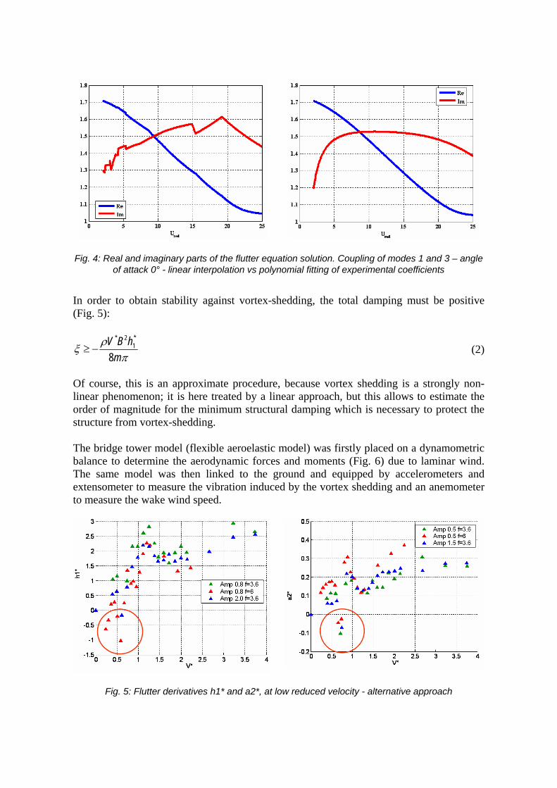
Fig. 4: Real and imaginary parts of the flutter equation solution. Coupling of modes 1 and 3 – angle of attack 0° - linear interpolation vs polynomial fitting of experimental coefficients
In order to obtain stability against vortex-shedding, the total damping must be positive (Fig. 5):
* 2 *1
8V B h
mρξ
π≥ − (2)
Of course, this is an approximate procedure, because vortex shedding is a strongly non-linear phenomenon; it is here treated by a linear approach, but this allows to estimate the order of magnitude for the minimum structural damping which is necessary to protect the structure from vortex-shedding. The bridge tower model (flexible aeroelastic model) was firstly placed on a dynamometric balance to determine the aerodynamic forces and moments (Fig. 6) due to laminar wind. The same model was then linked to the ground and equipped by accelerometers and extensometer to measure the vibration induced by the vortex shedding and an anemometer to measure the wake wind speed.
Fig. 5: Flutter derivatives h1* and a2*, at low reduced velocity - alternative approach

Fig. 6: Aerodynamic coefficients at the pylon base.
The aerodynamic forces are used in the design of the pylon sections. The wake wind speed spectral properties (Fig. 7a,b) allow to determine the Strouhal number, while the low increment of the bending moment (in the pylon) at the lock-in velocity (Fig. 7c) shows a moderate sensibility to vortex shedding. 3. THE NEW BRAGA STADIUM The tests for the design of the new Braga Stadium suspended roof were carried out, independently, at the RWDI and at the “Politecnico di Milano” wind tunnel. RWDI tests were performed on rigid models, to measure the pressure field on the roof. At the “Politecnico di Milano”, was tested a flexible (aeroelastic) model, to check the aerodynamic stabilities and the effectiveness of a possible external damping system. Hence, the wind pressures were derived from the tests on a rigid model (Fig. 8). Since the pressure time histories were simultaneously measured at different points, within the upper and the lower sides of the roof panels, the instantaneous pressure fields were available.
Fig. 7: Spectral properties of the wake (a, b) and base bending moment vs wind speed (c).

Fig. 8: The New Braga Stadium and the RWDI pressure taps arrangement. As a matter of fact, due to the different spatial distribution of upper and lower pressure taps, preliminary interpolation was required to obtain the differential pressures, which represent the actual load on the structure. Despite the apparent simplicity of this operation, the instantaneous interpolation gave rise to uncertainties and numerical difficulties. The design wind speeds at the stadium site were derived from 1:1500 scaled wind tunnel tests (including a wide stadium surroundings), while the pressure coefficients were measured in 1:400 model. Both the wind speed profiles and turbulence presented different features in 1:400 tests with respect to 1:1500 ones. In order to match the peak gust velocities between the two scale models at the 25 and 50 m (roof position) heights, an equivalent design wind speed was calculated by RWDI. The “double model” was a source of further uncertainties and data treatment problems. It also outlined a more general problem which often occurs in defining the model reference height: due to the imperfect reproduction of the wind profile, significant errors can befall when wind tunnel dimensionless coefficients are used with reference to standard codes design wind speed. The orthogonal decomposition techniques have been adopted to simplify the pressure representation, and to reduce the computational effort. The structural response was determined by separately evaluating the mean, the quasi-steady and the resonant response. The first term simply takes into account the mean pressure distributions. The second one is obtained by performing a classical covariance proper orthogonal decomposition (POD). The third one takes into account the dynamic amplification of a suitable number of structural vibration modes, each one being excited by the unsteady wind pressures.
Fig. 9: Proper orthogonal decomposition of the measured wind pressure fields.

Fig. 10: References points/regions for the response evaluation and the sensibility analysis (a) minimum reliability index β for each direction (b) and distribution of β values along the slab (c).
The analytical procedure is synthesised in the following expression, while a typical result is summarised in Table 1 (with the reference of Fig. 10a). The Eqs. (3) resume the procedure to decompose (POD) a pressure field (Fig. 9), the Eqs. (4) determine the mean and the quasi-static response and the Eqs. (5) are relative to the resonant contribution.
1
mT
p k k kkφ φ λ
== ∑C ; ;
i
T Ti j ij p j ij jφφ δ φ φ δ λ= =C ; ( ) ( )
1
m
k kk
t x tφ=
= ∑p . (3)
( ) ( )1
s
k kk
R t x t R=
= ⋅∑ ; 2 2 2,
1k k
s
R qs xk
Rσ σ=
= ∑ ; ,qs qs R qsR R g σ= ± . (4)
2 2 2 2
, ,qs res qs R qs res R resR R g gσ σ+ = ± + ; 2 2 2 2,
1h
n
res R res h Rh
g gσ σ=
= ∑ ;
( )( )
0.5772ln2lnh h
h
g f Tf T
= + ; ( ) ( )2, ,h hA
M m x y x y dAψ= ⋅ ⋅∫ ;
( ) ( ) ( ), , ,h hA
Q t p x y t x y dAψ= ⋅ ⋅∫ ; ( )
( )2 2
4 24 2h
h
h Q hR h
h h h
f S fR
f Mπσξ π
⋅=
⋅ ⋅ ⋅.
(5)
The resonant contribution is proportional to the square of the inherent structural damping ratio. Since this contribute was the most important in the case of the Braga Stadium (see Table 1), a more appropriate evaluation of the structural damping was necessary (full scale dynamic characterization) and an experimental check of the resonant and aeroelastic effects was made (aeroelastic model).
Table 1: Typical response contribution, in terms of vertical displacement at some roof locations: mean (col. 2), quasi-static (col. 4) and total response (col. 6).

Fig. 11: Monitoring system on the whole structure.
A sensibility analysis of the failure probability to the spatial distribution of wind loads was performed too. This analysis allowed to determine the wind direction which corresponds to the higher failure probability (Fig. 10b), to recognize the structure regions which have the higher failure probability.(Fig. 10c, where the black region show the lowest β values - 3.798) and to determine the wind loads spatial distribution which leads to the higher failure probability. An advantage of this technique with respect to the POD is that it considers both the wind stochastic structure and the structural response. The aeroelastic model (1:70) was tested al the “Politecnico di Milano” BLWT in both laminar flow (without external environmental reconstruction) and in turbulent flow (with external environmental reconstruction). The aeroelastic stability was checked up to 58 m/s (full scale). In turbulent wind conditions, oscillation up to 40-50 cm full scale, as order of magnitude, were recorded. The aeroelastic model was also tested by placing (at the roof corners) linear viscous dissipative devices (C = 100-150 kN s/m at full scale). Damping ratios up to 7-8% were reached. The response was subsequently reduced of about 50%, so confirming the analytical estimations.
Fig. 12: Images of the exciting system.

Fig. 13: Exciting-measuring positions (a), typical free motion record (b) and 1st natural mode (c).
Since January 2004, the structure was equipped with a permanent monitoring system, to measure different parameters (such as pressures, accelerations, wind velocity, cable stresses, etc.) at different significant point of the structure (Fig. 11). As it was found numerically and confirmed by the aeroelastic model, the resonant response is dominant and the structural inherent damping was a very important parameter in determining the response. The dynamic characterization was performed to determine the actual value of the damping ratio for the firsts modes. To excite the system, a cable was linked to the edge steel girder by mean of a pre-tensioned spring (Fig. 12a) and it was sinusoidally moved at the other end by an electrical engine (Fig. 12b). To measure the structural dynamic response under the applied dynamic loads and the free vibrations decay after the loading excitation stop, 6 accelerometers were placed on the roof slab (Fig. 13a). In order to evaluate the natural modal shapes and the corresponding modal damping, the free vibration decay time series, recorded after the resonant harmonic excitation stop, have been used (Fig. 13b). The modal shapes were determined by orthogonal decomposing (POD) the recorded signals (Fig. 13c). 4. THE UNIPOL TOWER The design of a tall building (123 m) was assisted by wind tunnel tests carried out at the CRIACIV (Prato, Italy) boundary layer wind tunnel on a rigid model 1:350 scaled and equipped with 125 pressure taps (Fig. 14).
Fig. 14: The Unipol Tower wind tunnel model (a) and the pressure taps locations (b).
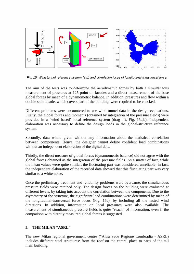
Fig. 15: Wind tunnel reference system (a,b) and correlation locus of longitudinal-transversal force.
The aim of the tests was to determine the aerodynamic forces by both a simultaneous measurement of pressures at 125 point on facades and a direct measurement of the base global forces by mean of a dynamometric balance. In addition, pressures and flow within a double skin facade, which covers part of the building, were required to be checked. Different problems were encountered to use wind tunnel data in the design evaluations. Firstly, the global forces and moments (obtained by integration of the pressure fields) were provided in a “wind based” local reference system (drag-lift, Fig. 15a,b). Independent elaboration was necessary to define the design loads in the global-structure reference system. Secondly, data where given without any information about the statistical correlation between components. Hence, the designer cannot define confident load combinations without an independent elaboration of the digital data. Thirdly, the direct measure of global forces (dynamometric balance) did not agree with the global forces obtained as the integration of the pressure fields. As a matter of fact, while the mean values were quite similar, the fluctuating part was considered unreliable; in fact, the independent elaboration of the recorded data showed that this fluctuating part was very similar to a white noise. Once the preliminary treatment and reliability problems were overcame, the simultaneous pressure fields were retained only. The design forces on the building were evaluated at different levels, by taking into account the correlation between the components. Due to the asymmetry of the structure, the significant load combinations were determined by mean of the longitudinal-transversal force locus (Fig. 15c), by including all the tested wind directions. In addition, information on local pressures were also available. The measurement of simultaneous pressure fields is quite “reach” of information, even if the comparison with directly measured global forces is suggested. 5. THE MILAN “ASRL” The new Milan regional government centre (“Altra Sede Regione Lombradia - ASRL) includes different steel structures: from the roof on the central place to parts of the tall main building.
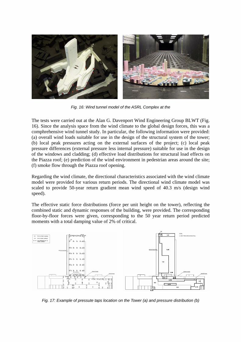
Fig. 16: Wind tunnel model of the ASRL Complex at the
The tests were carried out at the Alan G. Davenport Wind Engineering Group BLWT (Fig. 16). Since the analysis space from the wind climate to the global design forces, this was a comphrehensive wind tunnel study. In particular, the following information were provided: (a) overall wind loads suitable for use in the design of the structural system of the tower; (b) local peak pressures acting on the external surfaces of the project; (c) local peak pressure differences (external pressure less internal pressure) suitable for use in the design of the windows and cladding; (d) effective load distributions for structural load effects on the Piazza roof; (e) prediction of the wind environment in pedestrian areas around the site; (f) smoke flow through the Piazza roof opening. Regarding the wind climate, the directional characteristics associated with the wind climate model were provided for various return periods. The directional wind climate model was scaled to provide 50-year return gradient mean wind speed of 40.3 m/s (design wind speed). The effective static force distributions (force per unit height on the tower), reflecting the combined static and dynamic responses of the building, were provided. The corresponding floor-by-floor forces were given, corresponding to the 50 year return period predicted moments with a total damping value of 2% of critical.
Fig. 17: Example of pressute taps location on the Tower (a) and pressure distribution (b)
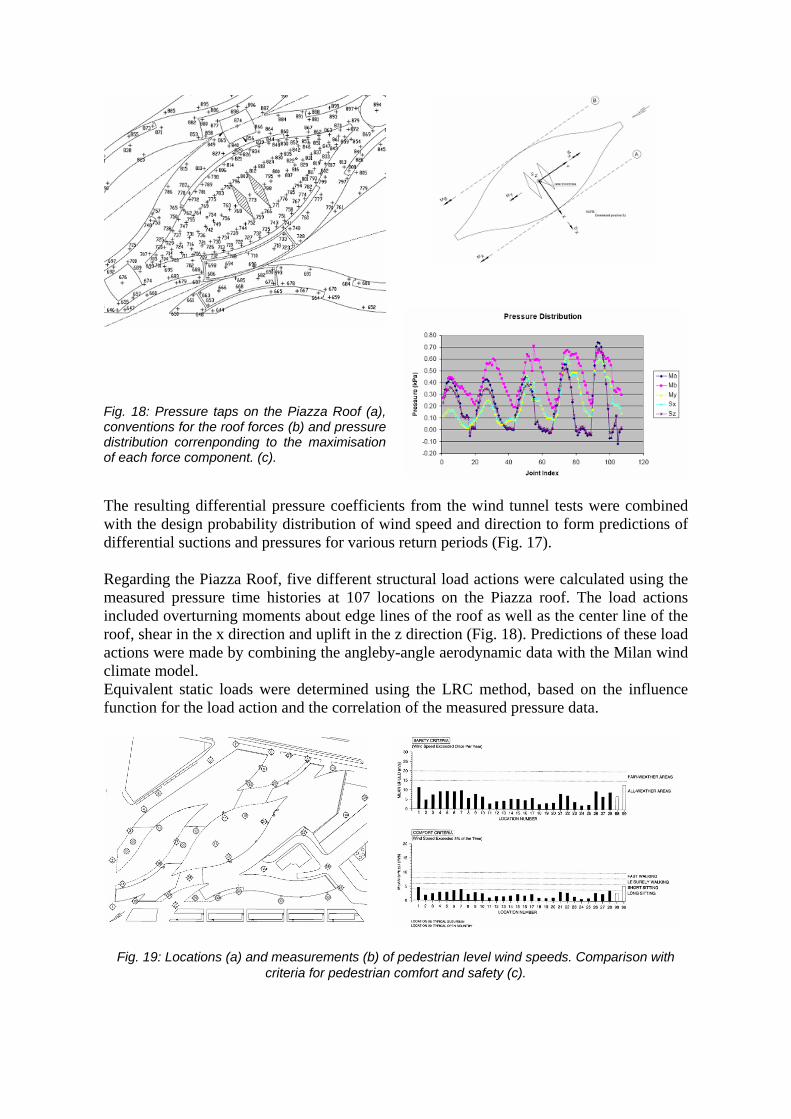
Fig. 18: Pressure taps on the Piazza Roof (a), conventions for the roof forces (b) and pressure distribution correnponding to the maximisation of each force component. (c).
The resulting differential pressure coefficients from the wind tunnel tests were combined with the design probability distribution of wind speed and direction to form predictions of differential suctions and pressures for various return periods (Fig. 17). Regarding the Piazza Roof, five different structural load actions were calculated using the measured pressure time histories at 107 locations on the Piazza roof. The load actions included overturning moments about edge lines of the roof as well as the center line of the roof, shear in the x direction and uplift in the z direction (Fig. 18). Predictions of these load actions were made by combining the angleby-angle aerodynamic data with the Milan wind climate model. Equivalent static loads were determined using the LRC method, based on the influence function for the load action and the correlation of the measured pressure data.
Fig. 19: Locations (a) and measurements (b) of pedestrian level wind speeds. Comparison with criteria for pedestrian comfort and safety (c).

Fig. 20: Bologna Town Hall model (a) and a typical force coefficients diagram on the roof (b).
Fig. 19a shows the locations where pedestrian level wind speeds were measured. Experimental results were combined with the extratropical wind climates to provide predictions of the wind speeds expected to be exceeded for 5% of the time and those expected to be exceeded once per year. These predictions were compared directly with acceptance criteria for pedestrian comfort and safety, respectively (Fig 19b,c). Finally, the effectiveness of the Piazza roof opening to allow smoke to escape was determined by the plume rise height of the smoke generated in the open space underneath the roof. Analytical calculations of the plume rise were carried out for low wind conditions as well as nominal 1 week return and 1 month return wind speeds. The results suggest that the plume rise heights are much larger than the height of the Piazza roof from ground and the smoke generated in a fire can likely escape the enclosure. 6. BOLOGNA TOWN HALL The Bologna town hall structural design was assisted by wind tunnel tests performed at the “Politecnico di Milano” BLWT. Two different models were arranged: a 1:50 model of the whole structure (Fig. 20a), for the measurement of loads on roofs and facades; a 1:1 model of a roof tube array (Fig. 22), to check the vortex shedding sensibility. The 1:50 model of the whole structure was used to measure the forces on the roof (by mean of dynamometric balances) and the pressures on facades (by mean of appropriate distribution of pressure taps). Loads on the roofs were given in terms of force coefficients (Fig. 20b), while pressures on facades were given in terms of pressure coefficient diagrams (Fig 21a,b) and global maps (Fig 21c). The building roof is covered by a series of tube arrays, regularly spaced. The length of tubes varies between 7 and 14 m. The length-diameter ratio (up to 39), the light weight (aluminium) and the end connection type (which arises a very low damping ratio, approximately ξ = 0.2%) make the tubes susceptible of dynamic excitation. Since the Scruton number is approximately 2.3, it is expected that the tubes are sensitive to vortex shedding excitation.

Fig. 21: Typical pressure coefficients on facades (a,b), pressure taps location (c) and typical pressure map (c).
In the case of isolated cylinder, this Scruton number value gives rise to oscillations of about 0.3 diameters. As a matter of fact, the array effect is also tested in the wind tunnel (Fig. 22). The results substantially confirm the previsions made for the single tube, the recorded displacement being 0.25 D as order of magnitude. In addition, wind tunnel tests showed that the tubes oscillation can reach amplitudes which can induce damage on the tubes themselves and on the connection and can induce appreciable oscillation on the whole roof. The wind “look-in” speed which is clearly in the range of the frequently expected wind speed at the structure site (Fig. 23).
Fig. 22: Wind tunnel model (a) and scheme (b) of one of the tube array.

Fig. 23: Accelerometers on a tube of the array (a) and spectral density function of the wind speed in the wake (b,c) for different angle of the array setup. Wind tunnel tests suggested to implement design solution to avoid or reduce the vortex shedding sensibility. Possible ways to do so are aerodynamic solutions (as, for instance, placing spires on the tubes) and/or adding mechanical damping to the tubes. The final designer-owner decision was to realize the roof without any countermeasure, to monitor it and to evaluate “on site” the opportunity of acting on the tubes (a case of design assisted by testing and monitoring). 7. REFERENCES
[1] MAJOWIECKI M., COSENTINO N. and COSTA C. “Wind Effects and Cables Damping at the Adige Cable Stay Bridge”, Proc. of IASS Symposium 2007, Venice December 3-6. 2007.
[2] MAJOWIECKI M. and COSENTINO N. “Dynamic Aspects of the New Braga Stadium Large Span Roof”, Proc. of IASS Symposium 2007, Venice December 3-6. 2007.
[3] MARINI M., COSENTINO, N. and MAJOWIECKI M. “Dynamic characterization of the New Braga Stadium large span suspension roof”, International Conference on Experimental Vibration Analysis for Civil Engineering Structures, EVACES, Bordeaux, France, October 2005.

[4] COSENTINO N. and MAJOWIECKI M., “Analysis and mitigation of the wind induced response of large span suspended roofs: the case of the new Braga Stadium”, Atti dell’8° Convegno Nazionale di Ingegneria del Vento - IN-VENTO-2004, Reggio Calabria, Giugno 2004.
[5] BERTERO R.D., CARNICER R. and PUPPO A.H. “Sensibility wind analysis of the roof structural system - Stadium of Braga – Portugal”, Final Report, September 2003.
[6] PUPPO A.H. and BERTERO R.D. “Evaluation of Probabilities using Orientated Simulation”, Journal of Structural Engineering, ASCE, Vol. 118, No. 6, June 1992.
[7] DIANA G., BOCCIOLONE M., COLLINA A., TOSI A. and ROCCHI, D. “Wind tunnel investigation on Braga Stadium”, Final Report, February 2003.
[8] BORRI C., BARTOLI G. and PROCINO L. “Edificio a torre di via Larga (Unipol): prove in galleria del vento per la determinazione delle pressioni sulle facciate e delle forze globali al suolo”, Rapporto finale, Maggio 2007.
[9] DIANA G. et al. “Comune di Bologna - Sede dei Servizi Unificati - Prove in galleria del vento su modello in scala 1:50 dell’intero complesso” Report 0202.PM.RC-F.001.001, Luglio 2005.
[10] DIANA G. et al. “Comune di Bologna - Sede dei Servizi Unificati - Prove in galleria del vento su un modello in scala 1:1”, Report 0202.PM.RC-F.002.001, Luglio 2005.
[11] QUIROGA P. “A study of wind effects for Milan Lombardi Government Center”, Report BLWT-SS21-2005, May 2005.