design and validation of automated authentication, …
TRANSCRIPT

DESIGN AND VALIDATION OF AUTOMATED
AUTHENTICATION, KEY AND ADJACENCY MANAGEMENT
FOR ROUTING PROTOCOLS
Revathi B S
A thesis
in
The Department
of
Computer Science and Software Engineering
Presented in Partial Fulfillment of the Requirements
For the Degree of Master of Computer Science
Concordia University
Montreal, Quebec, Canada
August 2012
c© Revathi B S, 2012

Concordia UniversitySchool of Graduate Studies
This is to certify that the thesis prepared
By: Revathi B S
Entitled: Design and Validation of Automated Authentication, Key
and Adjacency Management for Routing Protocols
and submitted in partial fulfillment of the requirements for the degree of
Master of Computer Science
complies with the regulations of this University and meets the accepted standards with
respect to originality and quality.
Signed by the final examining committee:
ChairDr. Brigitte Jaumard
ExaminerDr. Jaroslav Opatrny
ExaminerDr. Anjali Agarwal
SupervisorDr. J. William Atwood
ApprovedChair of Department or Graduate Program Director
20
Robin A.L. Drew, Ph.D.,ing., Dean
Faculty of Engineering and Computer Science

Abstract
Design and Validation of Automated Authentication, Key and Adjacency
Management for Routing Protocols
Revathi B S
To build secure network-based systems, it is important to ensure the authenticity and
integrity of the inter-router control message exchanges. Authenticating neighbors and en-
suring their legitimacy is essential. Otherwise, the routes installed could be erroneous or
targeted at causing an attack on the system.
Current methods, which are based on manual keying, are error prone, not scalable, and
result in keys being changed infrequently (or not at all) due to lack of authorized personnel.
These issues can be addressed only by having an automated key management system that
can automatically generate, distribute and update keys.
The issue can be cast as a group key management problem with a ‘keying group’ defined
as the set of all routers that share the same key. A keying group can be as large as an entire
administrative domain, or as small as a pair of peer routers. The smaller the scope of the
key the less damaging the loss of a single key is likely to be.
In this thesis, we propose an automated key management system that will be able
to handle different categories of keying groups and also ensure important properties such
as adjacency management, protection against replay attacks, confidentiality of messages,
smooth key rollover, and robustness across reboots. Although there is some ongoing work
with regard to developing automated key management systems, none of the existing methods
handles all these cases. We have formally validated the protocol designed, for essential
security properties such as authentication, confidentiality, integrity and replay protection,
using a formal validation tool called AVISPA.
iii

Acknowledgments
First and foremost, I am extremely grateful to my supervisor, Dr. J. W. Atwood, for his
valuable guidance, encouragement and suggestions throughout the course of this research.
He has been very patient and understanding, supporting me at every stage of this thesis
work. I consider myself very fortunate to have had an opportunity to work under his
supervision.
I would like to thank Concordia University and specially the Computer Science and
Software Engineering department, for granting me various scholarships to help aid my
studies. I would also like to thank all the faculty members who have helped me enhance
my knowledge in various topics related to this field.
I would like to express my deepest gratitude to my father, Somanatha B. R and my
mother, Rajeswari K. V for their endless love, encouragement and confidence in me without
which it would not have been possible to successfully complete this thesis. I would also like
to thank my sister, Ranjani and my brother-in-law, Prasad for their constant support and
motivation at every stage.
My special thanks to the rest of my family members and to all my friends for their
continued support and patience, which has meant a lot to me.
Most importantly I would like to thank God for his blessings without which I would not
have been able to achieve my Masters degree.
Once again, thanks to everyone.
iv

Contents
List of Figures viii
List of Tables ix
List of Acronyms x
1 Introduction 1
2 Background 4
2.1 Routing Protocols . . . . . . . . . . . . . . . . . . . . . . . . . . . . . . . . 4
2.2 Security Aspects . . . . . . . . . . . . . . . . . . . . . . . . . . . . . . . . . 5
2.2.1 IPsec . . . . . . . . . . . . . . . . . . . . . . . . . . . . . . . . . . . . 6
2.3 Key Management . . . . . . . . . . . . . . . . . . . . . . . . . . . . . . . . . 8
2.3.1 KARP and SIDR . . . . . . . . . . . . . . . . . . . . . . . . . . . . . 10
2.3.2 Need for yet another Key Management proposal . . . . . . . . . . . 11
2.4 Commonly Used Terms and Concepts . . . . . . . . . . . . . . . . . . . . . 12
3 Keying Groups (Key Scopes) 14
3.1 Keying Groups . . . . . . . . . . . . . . . . . . . . . . . . . . . . . . . . . . 14
3.2 Key Scopes . . . . . . . . . . . . . . . . . . . . . . . . . . . . . . . . . . . . 15
4 Existing Work 20
4.1 Unicast KMPs . . . . . . . . . . . . . . . . . . . . . . . . . . . . . . . . . . 21
4.1.1 IKE/ IKEv2 . . . . . . . . . . . . . . . . . . . . . . . . . . . . . . . 21
4.1.2 KMPRP . . . . . . . . . . . . . . . . . . . . . . . . . . . . . . . . . . 22
4.2 Group KMPs . . . . . . . . . . . . . . . . . . . . . . . . . . . . . . . . . . . 22
4.2.1 GSAKMP . . . . . . . . . . . . . . . . . . . . . . . . . . . . . . . . . 22
4.2.2 GDOI . . . . . . . . . . . . . . . . . . . . . . . . . . . . . . . . . . . 23
4.2.3 MRKMP . . . . . . . . . . . . . . . . . . . . . . . . . . . . . . . . . 23
v
4.2.4 G-IKEv2 . . . . . . . . . . . . . . . . . . . . . . . . . . . . . . . . . 24
4.3 An Automated Key Management Framework . . . . . . . . . . . . . . . . . 25
5 Problem Statement 26
5.1 Requirements . . . . . . . . . . . . . . . . . . . . . . . . . . . . . . . . . . . 26
5.1.1 Security Requirements . . . . . . . . . . . . . . . . . . . . . . . . . . 27
5.1.2 Non-Security Requirements . . . . . . . . . . . . . . . . . . . . . . . 27
5.2 Scope of the Problem . . . . . . . . . . . . . . . . . . . . . . . . . . . . . . . 28
5.3 Novelty of our Work . . . . . . . . . . . . . . . . . . . . . . . . . . . . . . . 29
6 High Level Design 30
6.1 Global View . . . . . . . . . . . . . . . . . . . . . . . . . . . . . . . . . . . . 30
6.2 Entities in the System . . . . . . . . . . . . . . . . . . . . . . . . . . . . . . 31
7 Detailed Design 34
7.1 System Design . . . . . . . . . . . . . . . . . . . . . . . . . . . . . . . . . . 34
7.1.1 Communication among the Entities . . . . . . . . . . . . . . . . . . 34
7.1.2 Inner View of a GM . . . . . . . . . . . . . . . . . . . . . . . . . . . 35
7.1.3 Hierarchical Design . . . . . . . . . . . . . . . . . . . . . . . . . . . . 36
7.2 Protocol Design . . . . . . . . . . . . . . . . . . . . . . . . . . . . . . . . . . 37
7.2.1 Step 1 - Initial Exchanges: GCKS, GM mutual authentication . . . 38
7.2.2 Step 2 - Key Management Message Exchanges between GCKS, GM 39
7.2.3 Step 3 - GM-GM mutual authentication . . . . . . . . . . . . . . . . 42
7.2.4 Step 4 - Key Management Message Exchanges between GMs . . . . 43
7.3 Variations for handling other Keying Groups . . . . . . . . . . . . . . . . . 45
7.4 A Sample Use Case . . . . . . . . . . . . . . . . . . . . . . . . . . . . . . . . 48
8 Other Aspects of the Key Management Problem 50
8.1 Key Updates . . . . . . . . . . . . . . . . . . . . . . . . . . . . . . . . . . . 50
8.1.1 Regular Key Updates . . . . . . . . . . . . . . . . . . . . . . . . . . 52
8.1.2 Router Installation/ Uninstallation . . . . . . . . . . . . . . . . . . . 53
8.2 Router Reboots . . . . . . . . . . . . . . . . . . . . . . . . . . . . . . . . . . 55
8.2.1 Supporting Unicast Routing . . . . . . . . . . . . . . . . . . . . . . . 59
8.3 Scalability . . . . . . . . . . . . . . . . . . . . . . . . . . . . . . . . . . . . . 59
8.4 Option to Turn Off Adjacency Management . . . . . . . . . . . . . . . . . . 60
8.5 Incremental Deployment . . . . . . . . . . . . . . . . . . . . . . . . . . . . . 60
8.6 Smooth Key Rollover . . . . . . . . . . . . . . . . . . . . . . . . . . . . . . . 61
vi

8.7 Eliminating Single Point of Failure . . . . . . . . . . . . . . . . . . . . . . . 62
9 Validation 63
9.1 AVISPA . . . . . . . . . . . . . . . . . . . . . . . . . . . . . . . . . . . . . . 63
9.2 HLPSL . . . . . . . . . . . . . . . . . . . . . . . . . . . . . . . . . . . . . . 66
10 Protocol Model using HLPSL 74
10.1 Overall Organisation of the HLPSL model . . . . . . . . . . . . . . . . . . . 74
10.2 Finer Details of the HLPSL model . . . . . . . . . . . . . . . . . . . . . . . 80
11 Results 84
12 Conclusion and Future Work 91
A The HLPSL Source Code 92
vii
List of Figures
1 Same key for the entire AD . . . . . . . . . . . . . . . . . . . . . . . . . . . 16
2 Key per link . . . . . . . . . . . . . . . . . . . . . . . . . . . . . . . . . . . . 17
3 Key per sending router . . . . . . . . . . . . . . . . . . . . . . . . . . . . . . 18
4 Key per sending router per interface . . . . . . . . . . . . . . . . . . . . . . 19
5 Key per peer router . . . . . . . . . . . . . . . . . . . . . . . . . . . . . . . 19
6 Protocol relationship diagram . . . . . . . . . . . . . . . . . . . . . . . . . . 20
7 An administrative domain . . . . . . . . . . . . . . . . . . . . . . . . . . . . 29
8 Global view of the system . . . . . . . . . . . . . . . . . . . . . . . . . . . . 31
9 Communication among the entities . . . . . . . . . . . . . . . . . . . . . . . 35
10 Inner view of a GM . . . . . . . . . . . . . . . . . . . . . . . . . . . . . . . . 36
11 Message exchanges for step 2 . . . . . . . . . . . . . . . . . . . . . . . . . . 41
12 Hashes used in step 2 . . . . . . . . . . . . . . . . . . . . . . . . . . . . . . 42
13 Message exchanges for step 4 . . . . . . . . . . . . . . . . . . . . . . . . . . 43
14 Hashes used in step 4 . . . . . . . . . . . . . . . . . . . . . . . . . . . . . . 44
15 Architecture of AVISPA tool [1] . . . . . . . . . . . . . . . . . . . . . . . . . 64
16 Structure of HLPSL specification [2] . . . . . . . . . . . . . . . . . . . . . . 66
17 Example of a protocol . . . . . . . . . . . . . . . . . . . . . . . . . . . . . . 67
18 Protocol simulation for one session . . . . . . . . . . . . . . . . . . . . . . . 86
19 Protocol simulation for five sessions . . . . . . . . . . . . . . . . . . . . . . . 87
20 Intruder simulation for five sessions . . . . . . . . . . . . . . . . . . . . . . . 88
viii

List of Tables
1 Results . . . . . . . . . . . . . . . . . . . . . . . . . . . . . . . . . . . . . . . 89
ix

List of Acronyms
AD Administrative Domain
AH Authentication Header
AS Autonomous System
AVISPA Automated Validation of Internet Security Protocols and Applications
DKS Domain Key Server
DR Designated Router
ESP Encapsulating Security Payload
FIPS Federal Information Processing Standards
GCKS Group Controller/ Key Server
GDOI Group Domain Of Interpretation
GM Group Member
GPAD Group Peer Authorization Database
GSA Group Security Association
GSAKMP Group Secure Association Key Management Protocol
GSPD Group Security Policy Database
HLPSL High Level Protocol Specification Language
IETF Internet Engineering Task Force
IGP Interior Gateway Protocol
IKE Internet Key Exchange
ISAKMP Internet Security Association and Key Management Protocol
KARP Keying and Authentication for Routing Protocols
KMP Key Management Protocol
KMPRP Key Management for Pairwise Routing Protocol
LKH Logical Key Hierarchy
LKS Local Key Server
LTL Linear Temporal Logic
x

MIKEY Multimedia Internet KEYing
MRKMP Multicast Router Key Management Protocol
NIST National Institute of Standards and Technology
PAD Peer Authorization Database
PBS Perfect Backward Security
PFS Perfect Forward Security
PIM Protocol Independent Multicast
RP Rendezvous Point
SA Security Association
SAD Security Association Database
SIDR Secure Inter-Domain Routing
SPAN Security Protocol ANimator for AVISPA
SPD Security Policy Database
SPI Security Parameter Index
SRTP Secure Real-time Transport Protocol
TEK Traffic Encryption Key
VPN Virtual Private Network
xi

Chapter 1
Introduction
Routing protocols exchange routing updates with their neighbors on a regular basis. Inter-
router control traffic exchanges should be made secure. It is extremely important to au-
thenticate neighbors to confirm that they are indeed who they claim they are. The traffic
is normally link-local in the sense that the control messages received by a router on a link
are not forwarded. In such cases, it is essential to provide for adjacency management in
order to ensure that the authenticated neighbors are also legitimate neighbors.
Current methods for securing inter-router control message exchanges are based on man-
ual keying. Manual methods clearly have multiple problems such as not being scalable,
being prone to errors and not aiding regular key updates. In many networks, keys config-
ured years ago are being used even today [3]. This opens up the possibility of attacks from
both active as well as passive intruders.
The solution to all these issues is the development of an automated key management
system. The system should be such that it can securely generate and distribute keys to
the intended recipient routers. An automated solution should also ensure that keys can be
updated as frequently as required.
The Keying and Authentication for Routing Protocols (KARP) working group within
the Internet Engineering Task Force (IETF) deals with, as the name indicates, secure keying
mechanisms for routing protocols. The ultimate goal of KARP [4] is to define “the use of
a key management protocol (KMP) for creating and managing the session keys used in the
message authentication and data integrity functions of the base routing protocols”. The
KARP working group has subsequently developed a “design guide” document [5] and a
“threats and requirements” document [3] to guide the work. It has also come up with a
number of proposals [6] for specific key management protocols. However, these proposals do
not take into account the need to consider a variety of key management models, and they
1

make no specific provision for ensuring the legitimacy of (supposedly) neighboring routers.
Along with the basic functionality of key generation, a secure automated key manage-
ment system should also satisfy a set of requirements or goals. We have compiled such a
set of requirements in Section 5.1 by listing them under two categories, security and non-
security requirements. Hence the key management problem can now be expanded to include
the development of an automated key management solution that satisfies all the specified
requirements.
In this thesis, we explain our proposal for a solution to the automated key management
problem. We have developed this system by building on the existing and ongoing work in
this field described in Chapter 2 and Chapter 4. We have extended some of the ideas in the
existing proposals so as to accommodate all the requirements specified in Section 5.1. We
have also designed a protocol for communication among the entities in the proposed design.
Finally we have completed a validation of the protocol using a formal validation tool called
AVISPA [1].
Before we proceed to explain in detail our proposal, in the next few chapters we give a
brief background and a description of the existing approaches showing what aspects of the
key management problem they address and what they fail to consider.
The thesis has been organized as follows:
• Chapter 2 gives the relevant background pertaining to the problem we are trying to
solve. It mainly discusses the security aspects of routing. It talks about a specific
security protocol (IPsec) and its requirements. It then lists some of the existing
protocols that have been proposed to solve the automated key management problem
and points out why there is still a need for a new protocol.
• Chapter 3 describes keying groups/ key scopes. The ability to handle all categories
of keying groups is identified as an important requirement of a KMP.
• Chapter 4 explains some of the existing and ongoing work in the field of automated
key management. This is an important chapter due to the fact that our design builds
on this work and extends it so as to be able to address key management issues not
handled by it.
• Chapter 5 states the exact problem we have attempted to solve. It lists the require-
ments to be satisfied by an automated key management system. It states the scope
of the problem and also gives the reasons due to which our proposal is novel.
• Chapter 6 gives a high level description of our design proposal describing the entities
in the system.
2

• Chapter 7 gives a detailed description of our proposal. Initially it explains the way
in which the entities in the system communicate with each other. It then proceeds to
describe the details of the message exchanges of the proposed protocol. The way in
which all categories of keying groups can be handled just by minor variations to the
basic protocol has also been shown.
• Chapter 8 addresses aspects of the key management problem other than key generation
and distribution. These are very important for building a scalable and easy to use
system. Among other things, it deals with key updates, router reboots, smooth key
rollover, and an option to turn off adjacency management if desired.
• Chapter 9 talks about protocol validation in general and a formal validation tool called
AVISPA in particular. The language provided by AVISPA, namely HLPSL, used to
describe the protocol being validated, has also been explained.
• Chapter 10 gives the details of the validation of the proposed protocol using AVISPA.
• Chapter 11 shows the results of the validation of our protocol. Our protocol has
been found to be safe by AVISPA. This chapter also goes over the requirements of an
automated key management system, and shows how our protocol helps satisfy all of
these.
• Chapter 12 presents the conclusion for the thesis and possible future work.
3

Chapter 2
Background
In this chapter, we shall see the background pertaining to the key management problem we
are trying to solve. We shall also see some concepts and terminology used in the thesis.
2.1 Routing Protocols
Routers are devices in the Internet that help forward data from a source to a destination.
Determination of the path to be followed for transferring a packet to its destination is
done through a process called routing. This process is carried out in accordance with
protocols called routing protocols. Each router needs to find the next hop to which it should
forward the data, the last hop being the intended destination. This calls for information
exchange among routers. Routers exchange routing updates that specify details of network
reachability and the costs associated with transferring data along a path. The aim is to
forward packets along the path associated with the least cost, which in turn could be based
on the number of hops, the bandwidth or another parameter depending on the requirements
of the traffic.
In the global Internet, a router cannot exchange path information and routing updates
with every other router since the resulting enormous traffic would overwhelm the entire
network. Hence a hierarchical model is adopted and routers are divided into groups such that
updates are exchanged among members within a group. The information is then summarised
and communicated by a representative router within the group to the corresponding router
from other groups. Each of these groups is called an Autonomous System (AS). An AS is
a set of routers under a single administration and having a single routing policy.
As mentioned, routers within an AS exchange route information among themselves.
Routing protocols used for this purpose are called Interior Gateway Protocols (IGPs). Com-
munication of the summarised information across ASes is done through protocols called
4

Exterior Gateway Protocols. Examples of IGPs are Routing Information Protocol (RIP) [7]
and Open Shortest Path First (OSPF) protocol [8]. An example of an Exterior Gateway
Protocol is Border Gateway Protocol (BGP) [9].
We also define something called an Administrative Domain (AD). An AD refers to a set
of routers under a single administration. The definitions of an AS and an AD look similar,
but it is to be noted that although an AD may be as large as the whole AS, it may also be
just a strict subset of the AS.
To summarise and to state more formally, according to [10], “The classic definition of
an Autonomous System is a set of routers under a single technical administration, using an
interior gateway protocol and common metrics to route packets within the AS, and using an
exterior gateway protocol to route packets to other ASes. Since this classic definition was
developed, it has become common for a single AS to use several interior gateway protocols
and sometimes several sets of metrics within an AS”. An IGP is, according to [11], “the
routing protocol used within a single administrative domain (commonly referred to as an
“Autonomous System”)”. According to [12], an AD is “The collection of resources under
the control of a single administrative authority. This authority establishes the design and
operation of a set of resources (i.e., the network).”
Routing protocols could be unicast or multicast. Unicast protocols are used for one-one
communication between two entities. An example of this is OSPF. Multicast protocols
are used for one-many communication among entities. An example of such a protocol is
Protocol Independent Multicast (PIM) [13].
A very important requirement of routing protocols and the routing updates exchanged
is security, as discussed in the next section.
2.2 Security Aspects
Routers in the Internet continually exchange control messages. These messages could be
of different types ranging from a ‘Hello’ to indicate peer liveness, to a routing update that
eventually determines the path along which data are to be sent. It could so happen that an
intruder eavesdrops on these messages and modifies them so as to have all data sent towards
himself. Depending on the severity of the attack, the results could even be disastrous. This
implies that the control message exchanges among routers have to be made secure. Security
has different aspects to it. Let us look at some of them now.
• Authentication - This deals with confirming that an entity is who he claims he is.
Routers need to authenticate each other before exchanging control messages.
5

• Authorization/ Access Control - This is all about ensuring that the entity is indeed
allowed to communicate with the other routers, send and receive updates. An entity
may be an authentic one, but may not be authorized to perform some actions. For
example, an entity may claim that he is ‘A’ and he may indeed be so. Hence au-
thentication would be successful. However, entity ‘A’ may not have the privileges to
exchange routing messages with other routers, for example, ‘B’ and ‘C’. This would
mean that ‘A’ is not authorized to perform those actions.
• Adjacency management - Most categories of control packets are exchanged only with
neighbors. For instance, the ‘Hello’ or the ‘Join’ messages of the PIM-SM protocol.
These are link-local and are not forwarded by a router. In these cases, it is essential to
verify before exchanging any information, if an authenticated entity is also legitimately
a neighbor. This could be done by each router obtaining a list of valid neighbors
(maybe through a central controller) and ensuring data origin authentication.
• Confidentiality - Some kinds of control message exchanges may have secrecy as a
requirement. Such messages should be encoded such that a third party or an illegal
recipient is not able to decipher it.
• Message integrity - This property deals with confirming that a message is received as
it was sent. It could have so happened that an active intruder has captured a message,
altered it and has then put it back into the network. Ensuring integrity helps detect
such attacks.
• Resistance to replays - An intruder could capture a routing update at some point of
time and replay the same message at a later point in time. This could cause erroneous
routing. This is because a routing update valid at some point of time may not be
valid later due to alteration of routes. Hence it is important to ensure that the routing
system is resistant to replay attacks.
A popular security protocol suite for IP that helps provide all of the above routing
security services is IPsec. IPsec is used in a variety of application areas, such as Virtual
Private Networks (VPNs) and basic firewall components. Let us now look briefly at IPsec,
its functionality and requirements.
2.2.1 IPsec
IPsec is a protocol suite used for securing IP based traffic. Among other things, IPsec
helps provide data origin authentication, confidentiality, protection against replay attacks,
6

access control and connectionless integrity [14]. IPsec includes two main protocols, namely,
Authentication Header (AH) and Encapsulating Security Payload (ESP). AH provides data
origin authentication, protection against replays, access control and data integrity. ESP
provides all these along with confidentiality. IPsec can be implemented in hosts as well as
in security gateways.
IPsec can operate in either of two modes, namely, transport mode and tunnel mode. In
transport mode, only the payload of an IP packet is secured when ESP is used, and the
payload along with selected portions of the header when AH is used. However in tunnel
mode the entire IP packet including the header is secured and a new IP header is added.
Usually, transport mode is used for host-host communication and tunnel mode is used for
host-security gateway and security gateway-security gateway communications.
IPsec employs the concept of a Security Association (SA). This actually refers to the set
of parameters used for securing traffic and can be viewed as a kind of connection between
entities. An SA mainly comprises of a set of algorithms, keys, key lifetime and directionality.
Of course an SA would have an identifier. This identifier is called a Security Parameter
Index (SPI). For unicast traffic, the SPI alone is used to distinguish SAs. However for
multicast traffic, the SPI is used in conjunction with the source address and the destination
address to identify an SA.
IPsec defines the use of some specific kinds of databases [14]. They are as follows:
• Security Association Database (SAD) - Each entry in this database specifies the pa-
rameters corresponding to an SA. Each SA is used for securing a particular set of
packets. Hence every entry in the SAD has the details of an SPI, a cryptographic
algorithm, a traffic key, key lifetime and direction, protocol mode and some other
parameters.
• Security Policy Database (SPD) - This database serves as a mapping between the
different classes of packets and the corresponding SA that is to be used to secure
each class. Depending on the particular SA to be used, further details of the SA are
obtained by looking up the SAD. The outcome of the SPD lookup for a particular
type of traffic is either one of ‘protect using IPsec’, ‘bypass IPsec’, or ‘discard the
packet’.
• Peer Authorization Database (PAD) - This database has details specifying the peers of
an IPsec entity that are authorized to communicate with the entity. It also mentions
the way in which peers can authenticate each other.
7

The above explanation holds good for unicast communication. For multicast communi-
cation, there are small variations. Multicast extensions to IPsec are defined in [15]. For the
multicast case, instead of an SA, IPsec defines the concept of a Group Security Association
(GSA). The GSA is shared by a multicast sender along with the corresponding receivers.
Whereas only the SPI is sufficient to map an inbound packet to an SA in the unicast case,
for multicast the SPI is used in conjunction with the source address and the destination
address. For unicast communication, the SPI can be determined by the receiver. However
for multicast, since there are multiple receivers, SPI assignment may have to be done by a
central controller or some negotiation protocol.
The IPsec databases corresponding to multicast communication are also extended ver-
sions of the databases for unicast. The SPD is replaced with a Group Security Policy
Database (GSPD). The GSPD supports unicast communication and introduces an extra
attribute called ‘Directionality’. The value ‘Symmetric’ means that a pair of SAs are to
be created, one in each direction, ‘Sender only’ and ‘Receiver only’ indicate that a single
SA is to be created in the outgoing or incoming direction respectively. This is because
multicast traffic cannot have a symmetric SA since a multicast address can never occur
as the source address of a packet. The PAD is replaced with a Group Peer Authorization
Database (GPAD). GPAD includes information regarding special entities such as the central
controller as well. The SAD is almost similar to the SAD of the unicast case, except that
the SPI assignment would not be done by the receiver. As noted above, it would probably
be done by a central controller.
Hence IPsec can be used for securing routing protocol traffic for both unicast and multi-
cast cases. The obvious question now would be regarding the manner in which the keys and
algorithms required for an SA/ GSA can be obtained. This can be done either manually
or by means of a key management protocol. Let us see the details of these two methods in
the next section.
There are many documents that talk in detail about IPsec and its protocols, AH and
ESP. Information regarding the organization of these documents can be found at [16].
2.3 Key Management
Key management, or in fact, SA management is the core requirement for a security protocol.
In the previous section, we have seen the details of a security protocol suite, namely, IPsec.
We mentioned that IPsec uses the concept of an SA, which includes various parameters such
as cryptographic algorithms and traffic encrypting keys. Generation of these parameters is
the primary requirement for IPsec or any related security protocol.
8

SA parameters can be generated in either of two ways—manually, or automatically. In
the manual method, an administrator goes to each one of the devices (hosts or routers) and
configures the parameters on them. This method is error prone. Although there may be a
large number of administrators each managing his respective set of devices, when multiple
devices are being configured, there is a high possibility of occurrence of errors. Secondly,
the manual method is not scalable. Administrators cannot be expected to manage the
configurations for the exponentially growing Internet, with its size almost doubling every
nine to fourteen months [17]. Thirdly due to lack of administrators, or people authorized
to configure the devices, SA parameter updates cannot be done frequently and routers keep
using old keys. This poses a threat of attacks from intruders. An intruder could be passively
observing the traffic flow and could have gained access to the traffic keys used. If the keys
are not changed regularly, the intruder would be able to decode all packets being transferred
thereby making him successful in altering the packets according to his desire.
These issues can be eliminated by deploying an automated system for SA management.
An automated system once correctly programmed, can eliminate configuration errors, prove
to be scalable, and provide the flexibility to perform key updates as frequently as desired.
These advantages led to the proposal and development of key management protocols for
automated management of keys and other SA parameters.
The most popular among the key management protocols existing since a long time is the
Internet Security Association and Key Management Protocol (ISAKMP) suite of protocols
[18]. From this suite, the most prominent ones are Internet Key Exchange (IKE) [19] for
unicast communication, Group Domain Of Interpretation (GDOI) [20] and Group Secure
Association Key Management Protocol (GSAKMP) [21] for multicast communication.
IKE provides the SA parameters required for pairwise communication among entities.
IKE also has an updated version, IKEv2 [22]. IKE was originally defined in 1998 and hence
it has been around since a long time.
GDOI provides SA parameters required for group communication. In fact GDOI is based
on IKE. GDOI has been in existence since 2003 [23]. It is capable of supporting applications
secured using IPsec ESP. However it can also be extended to support applications using
other security protocols.
There is a Multicast Group Security Architecture document [24], which was proposed
in 2004. This document talks about security services required by group communication as
well as aspects pertaining to key management. It proposes two reference frameworks for
multicast security, a centralized framework and a distributed one.
GSAKMP is a group key management protocol that was proposed in 2006 conforming to
the Multicast Group Security Architecture. GSAKMP has been derived from the ISAKMP
9

framework [18] and the FIPS Pub 196 [25].
In fact, an updated version of GDOI [20] was also proposed in 2011 conforming to the
Multicast Group Security Architecture.
At this point, it is good to observe that another key management protocol has been in
existence since 2004, and that is Multimedia Internet KEYing (MIKEY) [26]. This protocol
is used to provide SA parameters for Secure Real-time Transport Protocol (SRTP), which in
turn is used to secure real-time multimedia applications. Since we are dealing with securing
router control traffic, which is mainly achieved through IPsec, our domain is different from
that dealt with by MIKEY and hence we do not discuss the details of this protocol in this
thesis.
Let us now take a brief look at some of the work currently happening in the IETF
working groups with regard to automated key management. This work has been explained
in detail in Chapter 4.
2.3.1 KARP and SIDR
KARP and SIDR are working groups within the IETF. KARP stands for ‘Keying and
Authentication for Routing Protocols’ [4]. This working group deals with the security and
key management for IGPs. SIDR stands for ‘Secure Inter-Domain Routing’ [27]. This
working group deals with the security for Exterior Gateway Protocols. An example of work
going on in SIDR is the proposal of a security extension to BGP, called BGPSEC [28].
In this thesis, our focus is on the key management for router control packets within an
AD. Since we are concerned only with the automated key management for securing IGPs,
we shall focus mainly on the work going on inside the KARP working group.
KARP has come up with some proposals for automated key management. ‘Key Manage-
ment for Pairwise Routing Protocol’ (KMPRP) [29] has been proposed for unicast commu-
nication. ‘The Use of G-IKEv2 for Multicast Router Key Management’ [30] and ‘Multicast
Router Key Management Protocol’ (MRKMP or MaRK) [31] have been proposed for multi-
cast communication. In fact these protocols are based on some of the time tested protocols,
namely, IKEv2 and GDOI.
KMPRP extends IKEv2 by being generic enough to automatically provide keys for all
unicast routing protocols. IKEv2 was more focused on generating keys for the security
protocol, IPsec.
The proposal about using G-IKEv2 for multicast router key management is, as the
name indicates, based on the G-IKEv2 proposal [32]. G-IKEv2 protocol is based on GDOI.
The difference between the two is that whereas GDOI is a group key management protocol
10

based on IKE, G-IKEv2 is based on IKEv2 which is simpler than IKE. G-IKEv2 conforms
to the Multicast Group Security Architecture. One of the advantages of coming up with this
variant of GDOI was better performance due to reduced number of message exchanges. The
proposal about using G-IKEv2 for multicast router key management talks about one of the
modes in which G-IKEv2 can be used for securing routing protocols using a one-to-many
communication model.
MRKMP is also based on IKEv2 and GDOI, and acts as a companion to the proposal
about multicast router key management using G-IKEv2. MRKMP is different from GDOI in
that it describes an election protocol for the group controller. GDOI proposes a centralized
group controller chosen by an administrator.
All of the above proposals are undoubtedly very well thought of ideas and help solve
the key management problem in innovative ways. However we felt that they are missing a
couple of key issues to be considered while designing an automated key management system.
We explore this in the section that follows.
2.3.2 Need for yet another Key Management proposal
We have already seen that there are multiple proposals intending to solve the problem of
automated key management. While they seem to be successful in being able to automatically
generate and distribute keys to recipient routers, there are a few issues not addressed by
them. Firstly a key management solution should recognize and accommodate all possible
categories of key scopes. Key scopes are explained in detail in Chapter 3. Briefly, key scopes
refer to the expanse of a key, that is, the number of routers using the same key. The situation
could be such that all routers in an AD share the same traffic key to secure their control
packets, or each router could use its own separate key to secure its traffic. Generating
and distributing traffic keys for each of these individual cases needs to be thought of. The
existing proposals for key management do not take into account the variety of key scopes.
Secondly for control packets that are exchanged in a link-local manner, management of
adjacencies is extremely important. As already mentioned such packets are to be exchanged
only with legitimate neighbors and hence checks to confirm the validity of neighbors should
be done before the actual communication begins. This in turn involves issues such as the way
by which routers in an AD can obtain information pertaining to their legitimate neighbors.
The existing proposals do not address this important issue. Finally the existing approaches
handle automated key management either for unicast communication or for multicast but
not for both. It would be good to have a single generic solution that accommodates both
categories of communication.
11

Due to these reasons, we have come up with a proposal. This proposal not only handles
automated generation, distribution and update of keys, but also accommodates the issues
overlooked by the current methods. A point to be noted is that our proposal is not restricted
to IPsec; it can easily be used by any protocol requiring keys. We have initially come up
with a list of requirements to be satisfied by a key management protocol in Section 5.1. We
have then proposed the design of a protocol that satisfies all of the stated requirements.
We have also shown the exact message exchanges for the protocol. Finally we have vali-
dated the proposed protocol using a formal validation tool called AVISPA. Since there is
already a variety of key management proposals in existence, we have not designed a protocol
from scratch. Instead we have reused parts of existing protocols/ proposals and modified/
enhanced them so as to meet all the requirements.
2.4 Commonly Used Terms and Concepts
There are some concepts and terminology common to most of the existing key management
proposals. We adopt these concepts and hence we make a brief mention of them here so
that it would be easier to appreciate a description of the current approaches in Chapter 4.
We have seen the concept of an AD. Within an AD, there are multiple routers. One of
these routers (or sometimes a server) is chosen by the administrator to take up the main
responsibility of key management. This entity is called the Group Controller/ Key Server
(GCKS). The routers other than the GCKS that wish to communicate with each other in
the AD are called Group Member (GM) routers. GMs exchange control messages among
themselves and these need to be secured using a security protocol such as IPsec. A key
management protocol should therefore generate and provide the keys and other parameters
required by the security protocol for securing the router control traffic. The protocol for
key management runs between the GCKS and GMs and among the GMs themselves, and
is referred to as the Key Management Protocol (KMP). The keys derived and given to
the routing protocols for protecting their control traffic are called Traffic Encryption Keys
(TEKs). The keys along with their lifetime, directionality, and the algorithms to be used
are together referred to as a Security Association (SA). The keys are placed into a key table
from where they can be accessed by the routing protocols. A key table is a database as
defined in [33] where a variety of attributes pertaining to a key can be stored.
These concepts are common to most existing work, a minor difference would be in the
exact terms used for these concepts by the different proposals. One other point worth
mentioning is that the existing proposals for unicast key management do not make use of
the concepts of a GCKS and GM. Currently, GCKS and GM concepts are employed only
12

by multicast key management protocols.
Having seen a background of our work and the reasons why we had to come up with
an enhanced key management protocol, we now explore the concept of keying groups—a
concept majorly responsible for our proposal of a new protocol.
13

Chapter 3
Keying Groups (Key Scopes)
Before we go into the details of the existing work leading to our design proposal, we introduce
the concept of keying groups and key scopes. This is a very important concept since an
automated key management system should be designed so as to accommodate all categories
of keying groups. The KARP Operations Model document [34] makes a brief mention of
key scopes. However, this is a document that focuses on the issues to be considered when
designing an operational and management model hence it does not talk about any particular
design for automated key management. We have written a separate chapter for this topic
because none of the existing proposals for an automated key management system addresses
the possible variations of key scopes. Our solution has been designed to be generic enough
to accommodate all keying groups; this in fact represents a novelty of our research and
hence we felt that the concept deserves to be highlighted.
3.1 Keying Groups
In an AD, all routers having the same TEK can be referred to as forming a ‘keying group’.
We can have routers forming a ‘keying group’ as follows:
1. A group per AD - This is the most coarsely grained category of keying group where
all routers in an AD share the same traffic key. Hence the incoming and outgoing keys
for protecting control traffic on all routers are the same. This is the case typically in
usage today with manual keying.
2. A group per link - Here, all routers sharing a link share the key for that link. The
routers could have different keys on their different interfaces, and share them with the
other routers connected to those respective links.
14

3. A group per sending router - This category is more finely grained compared to the
previous two cases; each router uses a different key to secure its outgoing control
traffic.
4. A group per sending router per interface - This is the most finely grained category
wherein each router has a different key for each of its interfaces, which in turn is
different from the keys used by other routers to secure their outgoing traffic.
5. A group per peer router - This category is strictly for unicast communication wherein
peer routers share keys for their interaction. There is one outgoing key corresponding
to each router in every pair of routers. These keys can be established through a
unicast key management protocol such as IKE [19] or IKEv2 [22].
3.2 Key Scopes
Alternatively, keying groups can be viewed from another perspective. Instead of looking at
the granularity of keying from the point of view of the routers, we can look at it from the
point of view of the keys. This can be referred to as ‘key scope’. This viewpoint helps us to
show the number of different keys required in an AD with an arbitrary number of routers
‘n’. During this calculation, we consider that every router in the AD is a sending router
and hence uses keys to secure its control traffic. In fact, it is true that every router is a
potential sender as far as control traffic is concerned.
The key scopes corresponding to the above categories of keying groups in the same order
could be defined as follows:
1. Same key for the entire AD
Figure 1 shows that all routers in the domain share the same key K1. The outgoing
keys used by a router are mentioned on its respective interfaces.
Total no. of unique keys in the AD = 1.
2. Key per link
Figure 2 shows that all routers on a link share the same key. For example, routers
GM1, GM2 and GM4 share a link and use key K1 on that link. Similarly, GM2, GM3
and GM5 share another link and use key K2 on that link.
Total no. of unique keys in the AD <= n. This is because any link is shared by 2 or
more routers.
15

Figure 1: Same key for the entire AD
Of course if there are multiple loops in the network, with many possible paths between
the same two routers, the network could reduce to a system where every router is
directly connected to every other router. In this scenario, the number of unique keys
in the AD would be nC2 = ((n ∗ (n− 1))/2). However this is an extreme case, hence
for all practical purposes the initial calculation itself holds good.
3. Key per sending router
Figure 3 shows that each router has a different key to secure its outgoing control
traffic. For example, router GM1 uses key K1 as its outgoing key on all its interfaces.
Similarly GM2 uses key K2 as its outgoing key on all its interfaces. It is to be noted
that mentioning K1 and K2 on the different parts of the link between GM1 and GM2
does not mean that key K1 is used only on one part of the link and K2 on the other.
It is just used to depict the outgoing keys of the routers on their respective interfaces
so that we are able to count the total number of keys in the AD.
Total no. of unique keys in the AD = n, one corresponding to each router.
4. Key per sending router per interface
Figure 4 shows an AD in which each router uses a different key for each of its interfaces,
which in turn is different from the keys used by the other routers for securing their
outgoing traffic. For example, router GM1 uses key K1a as its outgoing key on one
of its interfaces and key K1b on its other interface. Similarly GM2 uses key K2a as
16

Figure 2: Key per link
its outgoing key on one interface and key K2b on the other. A point to be noted here
is that in order to count the number of keys required, each link would have to be
counted as many times as the number of routers on it.
Total no. of unique keys in the AD >= 2n. This is because each router has at least
2 interfaces. We are ignoring the fact that the border routers would be connected to
routers in different ADs.
The results above show that the scope of the key decreases from type 1 to type 4.
This implies that the damage caused due to loss of a single key decreases in the same
order.
5. Key per peer router
Figure 5 depicts unicast communication. Here, there exist two keys corresponding
to every pair of routers. For example, routers GM1 and GM2 communicate by GM1
using an outgoing key K12 and GM2 using outgoing key K21. Similarly GM1 and
GM4 communicate by GM1 using outgoing key K14 and GM4 using as its outgoing
key K41, and so on. The number of different keys required here depends on the
manner in which routers are connected. Theoretically, it is minimum when routers
are connected in the form of a straight line and it is maximum when each router has
a connection to every other router.
Total no. of unique keys in the AD:
Minimum = (2n− 2), ignoring the border routers, which are connected to a router in
17

Figure 3: Key per sending router
another AD, and,
Maximum = 2 ∗ nC2 = n ∗ (n− 1).
18

Figure 4: Key per sending router per interface
Figure 5: Key per peer router
19

Chapter 4
Existing Work
In this chapter, we look at some of the existing work in the area of automated key man-
agement. We also see what aspects of the key management problem they solve and what
aspects they fail to consider.
We have seen a brief description of the existing work in Chapter 2. There we have
mentioned the relationship among the different key management protocols in existence and
what exactly led to the development of each of them. Let us now see that relationship in
the form of a diagram in Figure 6. The RFC/ publication numbers are mentioned alongside
the names of the protocols/ documents.
Figure 6: Protocol relationship diagram
20
From Figure 6, ISAKMP is at the root of the relationship tree and all key management
protocols are based on it. ISAKMP is actually a framework for the development of these
protocols. It defines key generation and entity authentication methods. It serves to support
security protocols at all layers of the network stack [18]. The IKE protocol, from which
most of the other protocols are derived, is also based on the ISAKMP framework.
The other publication that serves as a parent for one of the key management protocols,
GSAKMP, is the FIPS Pub 196 [25]. This stands for ‘Federal Information Processing
Standards Publication 196’ and is a publication by the National Institute of Standards and
Technology (NIST).
The third document that serves as a guidelines and architecture document for group key
management protocols is the Multicast Group Security Architecture document [24]. The
multicast key management protocols we are going to discuss in this chapter are based on
this document.
Let us now look at the details of each of the protocols from Figure 6 in order to know
why it was developed/ proposed, its strengths and weaknesses. We describe the unicast
protocols first followed by the multicast ones.
4.1 Unicast KMPs
4.1.1 IKE/ IKEv2
IKE stands for Internet Key Exchange [19]. It is a protocol based on the ISAKMP frame-
work. IKE is a key management protocol that generates keys to be used for securing unicast
protocols.
IKE has two phases of message exchanges. The first phase involves authentication
between the two parties and generation of a secure channel or a security association to
protect the next phase. The second phase is where keys are generated to be used by other
protocols. This phase is protected by the SA derived in phase 1. A single phase 1 could be
used for multiple phase 2 exchanges.
Among other things, IKE ensures authentication of peers, confidentiality of the key
management messages, and replay protection.
There is a version 2 of the IKE protocol and that is IKEv2 [22]. IKEv2 differs from IKE
in that it is simpler and more reliable than IKE. IKE and IKEv2 serve as the basis of most
of the other protocols we describe in this chapter.
21

4.1.2 KMPRP
KMPRP stands for ‘Key Management for Pairwise Routing Protocol’ [29]. KMPRP is an
ongoing work of the KARP working group of the IETF. This is a KMP to automatically
generate keys for securing message exchanges of unicast routing protocols. It is based on
the protocol IKEv2 [22] with the difference being that it is generic enough to be used for
providing keys for all unicast routing protocols, whereas IKEv2 was focused on providing
keys for IPsec.
The phases of KMPRP are similar to those of IKEv2. Although KMPRP assumes that
a way already exists for router authentication that can directly be used during the initial
exchange, it ensures peer authentication and a secure key exchange. It also ensures smooth
key rollover through the method defined in the KARP Crypto Key Table document [33].
However, KMPRP does not provide a method for adjacency management for unicast
communication, that is, a way by which routers can determine if an authenticated neighbor
is also a legitimate neighbor.
Having looked at the unicast key management work in this section, let us now have a
look at the group key management protocols and proposals.
4.2 Group KMPs
4.2.1 GSAKMP
GSAKMP stands for ‘Group Secure Association Key Management Protocol’ [21]. It is
a group KMP that was proposed in order to adhere to the guidelines in the ISAKMP
framework, the FIPS Pub 196, and the Multicast Group Security Architecture. The keys
derived by GSAKMP are mainly used to protect multicast application data.
The working of GSAKMP involves three main roles, namely, the Group Owner, the
GC/KS and the GMs. The GC/KS is the equivalent of the GCKS described in Chapter 2.
The group owner is responsible for defining security policies for the group. The GC/KS and
the GM routers are responsible for helping to enforce these policies. In addition, the GC/KS
handles key management. The GMs receive keys from the GC/KS and use them to protect
the application traffic. There is an entity called the Subordinate Group Controller Key
Server (S-GC/KS) to help in distribution of the functionality of managing a large group.
GSAKMP deals particularly well with security policy enforcement and key management.
Also it is a scalable protocol due to the presence of the S-GC/KS. However, GSAKMP does
not seem to handle all possibilities of keying groups from Chapter 3, with the number of
keys ranging from a single one for the entire AD to a different one for each interface of a
22

router. It also does not provide any special means for adjacency management.
4.2.2 GDOI
GDOI stands for ‘Group Domain Of Interpretation’ [20]. This is a group key and group
SA management protocol. It is based on IKE [19]. The original version of GDOI [23] was
proposed before the Multicast Group Security Architecture guidelines document came out.
Hence a new version of GDOI [20] appeared later and that conformed to these guidelines.
The original version of GDOI was published before GSAKMP, the new version came out
much later compared to the GSAKMP protocol.
There are two phases in this—GDOI runs in phase 2 protected by a phase 1 protocol such
as IKE. It defines a GROUPKEY-PULL and a GROUPKEY-PUSH exchange to establish
data security and rekey SAs. GDOI also employs the concepts of a GCKS and GMs in its
architecture.
GDOI provides security for the key management messages themselves. It ensures mes-
sage integrity through the usage of hashes, and provides replay protection through the usage
of nonces and sequence numbers. GDOI supports algorithms such as Logical Key Hierar-
chy (LKH) to help provide Perfect Forward Security (PFS) and Perfect Backward Security
(PBS).
However, GDOI does not recognize the existence of different keying groups. Also, al-
though GDOI employs a centralized architecture and can possibly be extended to include
adjacency management, the document does not specify anything about adjacency manage-
ment.
4.2.3 MRKMP
MRKMP stands for ‘Multicast Router Key Management Protocol’ [31]. This is a KMP pro-
posed by the KARP working group in order to generate keys for securing message exchanges
of multicast routing protocols. MRKMP borrows concepts from IKEv2 and extends it to
the multicast environment. MRKMP is based on GDOI as well but differs from it in a major
way as explained below. MRKMP conforms to the Multicast Group Security Architecture.
MRKMP employs the concept of a GCKS to generate keys for the GMs just like GDOI.
However MRKMP is different from the other KMPs in that the GCKS is chosen through
an election process depending on the priority of the routers. Hence potentially any router
could be the GCKS. In the other group key management protocols, including GDOI, the
GCKS is a central entity chosen by the administrator.
MRKMP handles well the case where the members of a group of routers on a LAN need
23

to communicate with each other. Also, it is resistant to replay attacks through the usage
of sequence numbers. However, MRKMP does not recognize the possibility of the existence
of different categories of keying groups. It also does not provide a solution for adjacency
management. Typically, adjacency management requires a centralized architecture wherein
an authority is supposed to have knowledge of the adjacencies corresponding to all routers
in the system. If the GCKS is elected through an election as is the case with MRKMP,
adjacency management may be difficult to achieve since no router can be expected to have
knowledge of the adjacencies of all the routers.
4.2.4 G-IKEv2
G-IKEv2 is a protocol for generating keys to be used to secure group communication [32].
It is based on IKEv2, GDOI and the Multicast Group Security Architecture. G-IKEv2 is
proposed as a variant of GDOI based on IKEv2. GDOI is a protocol based on IKE. Hence
G-IKEv2 is simpler than GDOI and has improved performance. The KARP proposal about
using G-IKEv2 for multicast router key management [30] gives a use case of the G-IKEv2
protocol showing the way in which it can be used for securing routing protocols using a
one-to-many communication model.
G-IKEv2 also employs the concepts of a GCKS and GMs. The document says that it
does not specify what particular device needs to be given the job of GCKS, but it would
be most reliable for one of the GMs to become the GCKS.
G-IKEv2 ensures authentication of the GMs by the GCKS and secure key distribution
from the GCKS to the GMs. However, it is not clear whether adjacency management
would be possible with this architecture. Since it does not restrict the choice of a GCKS, if
one of the GMs is chosen as the GCKS initially and it always remains as such, adjacency
management would be easy. This would be similar to the GDOI case. However, if the
GCKS is always chosen through an election, the protocol would be similar to MRKMP and
would have the problem of adjacency management. Also, G-IKEv2 makes no mention of
the possibility of a variety of keying groups.
In fact the MRKMP and the G-IKEv2 use case documents are companions to each other
and there is discussion going on in the KARP working group to merge them.
We have now seen some details of the ongoing and existing work in the field of auto-
mated key management. Let us now look briefly at a paper that deals with automated key
management. This is an important piece of work for us since our research is an extension
of the work reported in this paper.
24

4.3 An Automated Key Management Framework
Atwood [35] has specified a high level design for an automated key management system. The
paper proposes a scalable architecture for the key management problem. It introduces the
concepts of a Domain Key Server (DKS) and a Local Key Server (LKS). The DKS is similar
to the GCKS in all other work described above. The LKS is an entity corresponding to
each speaking router. The LKS takes up part of the key management responsibility, which
enables distribution of functionality and enhances scalability. The paper also recognizes the
importance of adjacency management in a network of routers.
Overall the paper specifies a framework for key management. However, it does not
recognize different keying groups. Also it mentions that a protocol for communication
between the DKS and the LKS is yet to be designed and validated.
Our design builds on the work specified in this paper, extending it to come up with a
detailed design for an automated key management system, a protocol for communication
among the different entities and validation of the protocol using AVISPA.
25

Chapter 5
Problem Statement
In this chapter, we give precise details of the problem being addressed. As already men-
tioned in the previous chapters, the overall aim is to design a system for automated key
management so as to eliminate the disadvantages of the manual method of configuring keys.
The basic function of this automated system is secure generation of keys and their distri-
bution. It should also enable key updates at regular intervals so as to protect against both
active intruders as well as passive intruders who could be eavesdropping the traffic after
having gained access to the keys secretly.
Along with these basic goals, a key management system should satisfy an additional
set of requirements. These requirements ensure among other things, security, easy deploy-
ment, robustness and scalability. We have compiled this set after referring to the KARP
Design Guidelines [5], the KARP Threats and Requirements Guidelines [3] and the PIM-
SM Authentication and Confidentiality document [36]. The requirements are presented in
Section 5.1.
After listing the set of requirements, we put forth the scope of the problem being consid-
ered. Finally, we state the factors that we believe are not taken into account in the existing
key management solutions leading to the novelty of our research.
5.1 Requirements
For ease of understanding, we have classified the set of requirements into two categories,
namely,
1. Security Requirements
2. Non-Security Requirements
26

5.1.1 Security Requirements
1. Peer authentication for unicast and authentication of all members of the group for
multicast protocols.
2. Message authentication, which includes data origin authentication and message in-
tegrity.
3. Protection of the system from replay attacks.
4. Peer liveness.
5. Secrecy of key management messages.
6. Authorization to ensure that only authorized routers get the keys.
7. Adjacency management, which implies ensuring the legitimacy of neighbor relation-
ships of each router. Also providing an option to turn off adjacency management if
required.
8. Ensuring Perfect Forward Security (PFS) and Perfect Backward Security (PBS).
9. Resistance to man-in-the-middle attacks.
10. Resistance to DoS attacks.
11. Usage of strong keys; those that are unpredictable and are of sufficient length.
5.1.2 Non-Security Requirements
1. Ability to handle various categories of keying groups depending on the security level
required.
2. Possibility for easy and incremental deployment.
3. Smooth key rollover.
4. Robustness across router reboots.
5. Scalable design.
6. Single key management architecture accommodating both unicast and multicast sys-
tems.
27

Among other things, these requirements include authentication, confidentiality, replay
protection, adjacency management and the ability to handle a variety of keying groups.
Many of these requirements have been explained in Section 2.2. Keying groups have been
explained in Chapter 3.
Authentication has two parts to it. Member authentication refers to ensuring that an
entity is who he claims he is. Message authentication refers to ensuring that a particular
message arrives from a legitimate source, unaltered during transit.
Adjacency management is the ability to ensure that a communicating router is a legiti-
mate neighbor. This is extremely important for the link-local control traffic.
Another concept worth explaining is that of PFS and PBS. PFS is a property that
helps ensure that an existing router in the AD, if uninstalled, can no longer comprehend
messages exchanged by the remaining routers. PBS is a property that helps ensure that a
newly installed router cannot comprehend messages previously exchanged by the old routers.
These properties are essential to make sure that routers can access only the messages they
are entitled to. For multicast systems, usually PFS and PBS are achieved through key
updates on a router uninstallation or installation respectively.
Smooth key rollover is the ability to make sure that no packets are dropped when traffic
key updates happen. On a key update a transition from the old key to the new one takes
place. This should be smooth such that the last few packets secured using the old key are
also interpreted correctly.
Another desired property of a key management system is robustness across reboots.
When routers in the system reboot, there should be no loss of important information.
Also in cases where a centralized controller is present, care should be taken such that the
controller is not stormed with requests from all entities at the same time.
The list of requirements specified above hold good for unicast as well as multicast com-
munication.
5.2 Scope of the Problem
We limit the scope of our problem to key and adjacency management within an AD. This
is because it may be necessary to manage some parameters within an AD independently
of an AS, for example, adjacencies. Also, our design is based on IGPs, which run within
an AS. A random AD has been shown in Figure 7. Our focus is on securing the routing
protocol control packets and not data packets. The solution should take into account an
arbitrary number of senders in the AD. That is, every router in the AD could be a sending
router, and this is in fact true as far as control traffic is concerned. Also, all routers in the
28

AD that are participants in secure routing are assumed to be homogeneous having similar
cryptographic capabilities.
Figure 7: An administrative domain
5.3 Novelty of our Work
In Chapter 4 we have presented some details of various existing protocols that deal with
the automated key management problem. We have also shown their advantages and short-
comings. Although the solution proposed by each of the existing work suggests a way for
automated key generation and distribution, none of them handles all the requirements listed
in Section 5.1.
In this thesis, we propose a detailed design including a protocol for automated key
and adjacency management. This design has been created by reusing parts of the existing
proposals and extending them so as to satisfy all the requirements specified in Section 5.1.
The main novelty comes from the fact that the system and the protocol we propose can
handle all categories of keying groups from Chapter 3, hold good for both multicast as well
as unicast communication, and accommodate adjacency management. We believe that there
is no other work until now that handles these cases in particular. We have also validated
our protocol using a formal validation tool called AVISPA.
29

Chapter 6
High Level Design
In this chapter, we propose an architecture for an automated key management and adjacency
management system. In order to build this framework, we have reused parts of some existing
proposals and fitted them into their correct places in the overall architecture. We have then
extended/ modified them so as to handle the key management issues that they appear to
have overlooked. In order to verify the correctness of our protocol, we have used AVISPA
tool to formally validate it. As already mentioned in Section 5.2, our design deals with
securing the control traffic of routers within an AD.
We initially give a high level overview of the proposed architecture. In the next chapter
we shall see the details of the communication among the entities in the system and the
details of the protocol message exchanges.
6.1 Global View
A global view of our system has been presented in Figure 8.
From the figure, the Internet can be viewed as a collection of interconnected ADs.
The main entities in our system are the following:
1. Administrator
2. Policy Server
3. GCKS
4. Standby GCKS
5. GMs
These entities and their functions have been explained in Section 6.2.
30

Figure 8: Global view of the system
6.2 Entities in the System
The entities in our architecture have been listed in Section 6.1. In this section, we explain
briefly their functions and interactions in order to achieve the final goal of secure key and
adjacency management.
The list of entities is based on that in GSAKMP [21]. The difference is that the Group
Owner in GSAKMP has been replaced by a Policy Server, and the Subordinate GC/KS has
been replaced by a Standby GCKS in our design. We have chosen the term ‘Policy Server’
in order to be consistent with the Multicast Group Security Architecture specification [24],
and the term ‘Standby GCKS’ since it is not a subordinate in our design, but is a standby
that is capable of performing all operations performed by the active GCKS. Our design
conforms to the Multicast Group Security Architecture [24].
The network administrator makes configurations for the Policy Server and the GCKS.
Security policies go to the Policy Server, and configurations related to the AD go to the
GCKS.
Policy Server is the entity that manages security policies for the AD. The behavior of
the Policy Server we describe here draws contents from and is very similar to the ‘Group
Owner’ in GSAKMP. The security policies include general policies such as authorization
details for the GCKS, access control for the GMs, rekey intervals, as well as other specific
31

policies that may be necessary for the group. These policies are put together into a ‘Policy
Token’ [21] and sent to the GCKS.
The GCKS is either a router or a server chosen by the administrator as the group
controller. It is the entity whose major function is key management and adjacency man-
agement. The GCKS should also ensure that the security policies in the policy token are
enforced. This implies that whenever a GM requests keys from the GCKS, the GCKS should
enforce access control for the GM according to the terms specified in the policy token. The
administrator configures the GCKS with information such as the type of keying group to
be enforced for the AD and the adjacencies for each router in the AD corresponding to a
particular routing protocol (or a set of similar routing protocols). This is due to our pro-
posal that there could be one instance of a GCKS per routing protocol or a set of similar
routing protocols. This is in fact necessary because GCKS is the entity that should ensure
adjacency management, and adjacencies may be defined differently for different routing pro-
tocols. Also, according to the KARP Operations Model document [34], “KARP must not
permit configuration of an inappropriate key scope”. This means that each routing protocol
could have a different requirement of key scope and that needs to be satisfied. The GCKS
may also generate, distribute and update keys, depending on the type of keying group to
be enforced in the AD.
The Standby GCKS is an entity that is always kept in sync with the active GCKS, ready
to take over at any time should the active one fail. This design eliminates the possibility of
a single point of failure in a centralized system.
GMs are the group member routers that communicate with each other as well as with
the GCKS. When they request keys from the GCKS, they are given the keys along with the
policy token. GMs are required to check the rules specified in the policy token to determine
if the GCKS is authorized to act in that role. Each GM has a Local Key Server (LKS) [35].
It is a key generation and storage entity within the GM. A GM may sometimes be required
to generate keys itself depending on the category of keying group being enforced. This kind
of design ensures that the architecture is distributed in the sense that the key management
responsibility is divided between the GCKS and the LKSes.
From the description above, it can be seen that the architecture we propose is a balance
between a completely centralized model and a completely distributed one, developed by
picking the plus points of both types. It defines the concept of a GCKS, which is a centralized
entity, as well as the concept of an LKS, which is distributed as being one entity per
router. The design tries to bring in the advantages of both models. A centralized entity
is considered necessary mainly to make adjacency management possible. In the absence of
a central controller that has information about the adjacencies of each router in the AD,
32

individual routers may not be able to establish the legitimacy of their neighbors. Adjacency
management is especially important since we are dealing with control packets, which are
usually exchanged with immediate neighbors. At the same time, loading the centralized
entity with multiple responsibilities may lead to its failure. Hence we have a localized
entity that can take up some of the functions of the central controller as and when the
need arises. This enhances scalability, which is so important in a key management system.
Another factor leading to scalability is the presence of the Standby GCKS. A centralized
system could have the disadvantage of having a single point of failure. Our design tries to
eliminate this by defining a standby for the central controller that is always kept in sync
with it, ready to take over at any time.
33

Chapter 7
Detailed Design
In the previous chapter, we have seen only a high level description of the proposed architec-
ture for an automated key and adjacency management system. In this chapter, we provide
a detailed description of the system. This is followed by our proposal for a protocol for
communication among the various entities in the system. We specify the exact details of
the protocol message exchanges. We also show how our protocol can accommodate all vari-
ations of key scopes described in Chapter 3. The architecture and the protocol we propose
hold good for both unicast as well as multicast communication thus making it a generic
design.
7.1 System Design
In this section, we give a detailed description of the proposed architecture showing also the
communication among the different entities.
7.1.1 Communication among the Entities
Figure 9 gives a closer view of the entities in our design as described in Section 6.2 and
shows the interactions among them.
Basically there is a centralized GCKS in the system and localized LKS, local to each
GM router. The GCKS and the LKS have the ability to generate SA parameters through
a KMP, and to store them in a key store. The different scenarios to be considered and the
steps of communication are described in this section and the next.
34
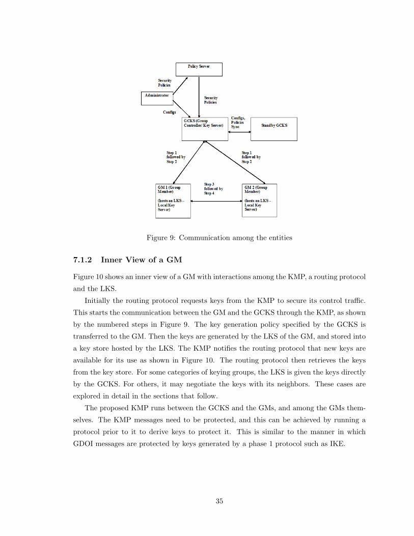
Figure 9: Communication among the entities
7.1.2 Inner View of a GM
Figure 10 shows an inner view of a GM with interactions among the KMP, a routing protocol
and the LKS.
Initially the routing protocol requests keys from the KMP to secure its control traffic.
This starts the communication between the GM and the GCKS through the KMP, as shown
by the numbered steps in Figure 9. The key generation policy specified by the GCKS is
transferred to the GM. Then the keys are generated by the LKS of the GM, and stored into
a key store hosted by the LKS. The KMP notifies the routing protocol that new keys are
available for its use as shown in Figure 10. The routing protocol then retrieves the keys
from the key store. For some categories of keying groups, the LKS is given the keys directly
by the GCKS. For others, it may negotiate the keys with its neighbors. These cases are
explored in detail in the sections that follow.
The proposed KMP runs between the GCKS and the GMs, and among the GMs them-
selves. The KMP messages need to be protected, and this can be achieved by running a
protocol prior to it to derive keys to protect it. This is similar to the manner in which
GDOI messages are protected by keys generated by a phase 1 protocol such as IKE.
35

Figure 10: Inner view of a GM
7.1.3 Hierarchical Design
The design we propose is a hierarchical one. In fact the operations of key management and
adjacency management occur at two different levels. To ensure scalability of the system, as
many operations as possible need to take place among adjacent routers. However, to ensure
overall control, policies need to be set centrally for the entire AD.
There are two kinds of groups that can be formed here (not to be confused with keying
groups from Chapter 3). The first one is the group formed by the GCKS and all the GMs
in the AD. The second one refers to many small groups, each consisting of a set of adjacent
GMs. The design can be seen as comprised of 5 main steps. The steps together help ensure
key and adjacency management in a secure manner.
Step 1 - Mutual authentication between the GCKS and each GM in the AD in order to
establish a secure path between them.
36

Step 2 - Communication between the GCKS and each GM in the AD for secure distribu-
tion of policy information. This policy information defines the key management approach
and parameters and the adjacency management approach and parameters.
Step 3 - Inter-GM authentication, in order to establish a secure path between pairs of
adjacent GMs, where the legitimacy of the adjacency was established in step 2.
Step 4 - Communication among the GMs themselves for exchange or generation of
the shared key (and other security parameters) that would be used to protect the routing
protocol packets.
Step 5 - The actual transfer of routing protocol control packets using the keys derived
through the previous four steps.
The steps have small variations depending on the key scope being enforced in the AD.
If the key scope corresponds to “same key for the entire AD”, then the key management
policy in step 2 could be “use this key”, where “this key” is the same for all GMs, and is
given as a parameter along with the policy. In this case, the key generation in step 4 is not
necessary. If the key scope corresponds to “key per link”, then the key may be mutually
determined by the routers on that link, or a “local” GCKS may be elected to assume the
task of generating the key, which will then be distributed on the secure paths established
in step 3. If the key scope corresponds to “key per sending router” or “key per sending
router per interface”, then the sending router assumes the responsibility for generating and
distributing the key(s) that it will use to secure its routing protocol traffic.
Similarly, if the key scope corresponds to “same key for the entire AD”, then the adja-
cency management policy is probably (but not restricted to) “accept any router that claims
to be your neighbor” or “accept any router that presents a valid router identification string”.
For other key scopes, the authentication part of step 3 would have to confirm that a match
exists between the identification presented by the neighboring router and that specified in
the adjacency management policy information.
Each step in the design is dependant on the previous ones leading to a hierarchy and
ensuring modularity of design. Our design concentrates on steps 1 through 4 in order to
enable a secure step 5.
The details of each of these steps are explained in the next section.
7.2 Protocol Design
In this section, we give a detailed description of our proposal for a protocol that serves
as a solution to the key management problem outlined in Chapter 5. To summarise, the
intention is to develop a protocol for an automated key and adjacency management system
37

such that all the requirements listed in Section 5.1 are satisfied.
We have seen the set of entities in the proposed design in Chapter 6. Now we shall see
the exact messages exchanged among them so that the keys required for securing routing
protocol control traffic can be generated and distributed to the appropriate routers.
Initially the administrator configures security rules on the Policy Server, and configura-
tion parameters on the GCKS. The security rules have among other things, access control
rules related to GMs, and authorization rules related to the GCKS. The configuration pa-
rameters include among other things, the key scope information pertaining to the AD and
adjacency information corresponding to each router in the AD. If required, the Policy Server
generates other security policies relevant to the group and puts them together into a policy
token. This policy token is sent to the GCKS.
Once this is done, steps 1, 2, 3 and 4 as outlined in Section 7.1.3 follow. Step 1 is for
GCKS-GM authentication, step 2 is for key and/ or policy transfer from the GCKS to each
GM, step 3 is for GM-GM authentication, and step 4 is for key exchange between GMs that
need to communicate with each other. Steps 2 and 4 have small variations depending on
the key scope being enforced for the AD.
Steps 1 and 2 are based on the GDOI GROUPKEY-PULL protocol [20]. However, step
2 in our case is an extension of GROUPKEY-PULL in the sense that it accommodates
various cases of keying groups and adjacency management as well. Steps 3 and 4 have been
designed such that GROUPKEY-PULL has been extended to inter-GM communication.
Now we shall look at each of these steps in detail.
7.2.1 Step 1 - Initial Exchanges: GCKS, GM mutual authentication
Initially, when a routing protocol instance wishes to start communication, be it unicast or
multicast communication, it informs the same to the KMP instance on the router. This
information is communicated by the KMP instance from that router to the KMP instance
on the router or server it believes to be the GCKS. At this point, the GCKS needs the
identity of the requesting router in order to authenticate it. The requesting router also has
to authenticate the GCKS. Any of the ISAKMP group of unicast protocols could be used for
step 1 communication between the GCKS and each router that requests keys from it. IKE/
IKEv2 is an example of such a protocol. This protocol provides peer authentication, and
parameters for an SA including a key to help provide confidentiality and message integrity
for the next step where the actual traffic keys would be generated. We call the key derived
in this phase as SKEYID a (term taken from GDOI). It is assumed that the routers have
38

agreed upon a way to establish their identity during authentication, either through pre-
shared keys, asymmetric keys or certificates. If peer authentication is successful, the router
becomes a GM.
As already mentioned, GM stands for ‘Group Member’. When talking about the GCKS-
GM interactions, ‘group’ typically means the entire set of GMs in the AD. When talking
about the GM-GM interactions, ‘group’ typically means the sending router and some set of
its neighbors. This set may include all of its neighbors or only a subset, depending on the
key scope in use. For example, when the key scope is per link, a ‘group’ may refer to all
routers sharing a link. This will become evident as we see the GM-GM interactions shortly.
Message Exchanges for Step 1
The protocol message exchanges for this step are the standard IKE exchanges since we
propose using IKE for this step. We would like to mention at this point that whenever we
say IKE, we intend to refer to IKE or IKEv2, unless explicitly stated otherwise.
7.2.2 Step 2 - Key Management Message Exchanges between GCKS, GM
This is the step where the KMP takes over. The goal of the KMP is to provide parameters
for an SA to be eventually used by a routing protocol to secure its control traffic.
Messages in this step are secured by the key generated by the step 1 protocol, that is,
SKEYID a. This key helps achieve authentication and confidentiality for step 2. For step 2,
we have taken most of the messages from GROUPKEY-PULL protocol of GDOI. However,
there are some modifications and important addition of functionality in our case, with the
GCKS passing additional information to the GMs. We shall see this in this section.
We shall initially look at the KMP details for one of the finely grained cases of keying
groups, namely, the group per sending router. This is a flavor of multicast communication.
Soon after this we will see the small variations necessary in order to handle the other
categories of keying groups.
In step 2, the (each) GM makes requests from the GCKS through the KMP for SA
parameters required to secure its control traffic. In the request to the GCKS, the GM
specifies the identity of the routing protocol for which it needs the keys. Although the
GCKS corresponding to the routing protocol would have already been selected in step 1,
specifying the routing protocol id again here helps to handle the case where the same GCKS
may be used for a category of similar routing protocols.
When the GCKS receives this request from the GM, it checks to verify if the GM can
be given access to key related information according to the rules in the policy token. If the
39

checks fail, the communication with the GM should not be continued. The exact behavior
can be determined from the rules in the policy token. If the checks succeed, the GCKS
delivers to the GM the following information:
• SA policy corresponding to the TEK. This could include the actual SA parameters
as well depending on the category of keying group being enforced. The TEK is the
traffic key whose scope could be anything among those described under key scopes
in Chapter 3. The SA policy includes policy information about SA parameters. This
could include information pertaining to the algorithms, the TEK, the SPI and other
parameters. For the category of keying group being discussed now, that is, the key per
sending router, the exact TEK and SA parameters are not delivered by the GCKS to
the GM. Only rules pertaining to their generation are handed down. The actual SA
parameters are generated later by the GM itself so that the GCKS is not overloaded.
• A certificate signed with the private key of the GCKS. This is to be used by the GM
for authentication purposes when it communicates with neighboring GMs and with
the GCKS for any SA updates in future.
• The policy token information received by the GCKS from the Policy Server. As
already mentioned, this includes authorization and access control related information.
This is read by the GM in order to authorize the GCKS and verify if it is entitled to
perform the role of GCKS.
• The key scope being enforced in the AD. This configuration is made by the adminis-
trator on the GCKS and is pushed to the GM. This is necessary so that the GM knows
whether to expect the traffic keys from the GCKS, or whether it needs to generate
them itself.
• The adjacency information, which includes details of all legitimate neighbors on all
interfaces of the GM and not only the neighbors online at that point of time. This is in
order to avoid a DoS attack on the GCKS that could result if the GMs started querying
the GCKS for every router coming up, especially during the boot up sequence, to
know if it is a legitimate neighbor. Also, this ensures completeness of information.
It even helps eliminate spoofing attacks where a legitimate neighbor may appear
on an interface other than the one it was supposed to appear on. The adjacency
information is used by the GM to know the set of authorized neighbors with which it
should communicate during steps 3 and 4.
40

Message Exchanges for Step 2
The protocol message exchanges for step 2 are shown in Figure 11.
GM->GCKS: HDR*, HASH(1), Ni, RP ID (1)
GCKS->GM: HDR*, HASH(2), Nr, SA, CERT,
K SCOPE, PT, ADJ (2)
GM->GCKS: HDR*, HASH(3) (3)
Figure 11: Message exchanges for step 2
In the message exchanges, HDR is an ISAKMP header payload. It has a message id
M-ID. The ‘*’ indicates that the message contents following the header are encrypted. The
encryption is done with SKEYID a. This ensures authentication (since the key is a secret
generated in step 1 and can be possessed only by the GCKS and the GM with which the
step 1 has been carried out) as well as secrecy (due to the encryption). Hashes are used for
ensuring message integrity and data origin authentication; this will be explained shortly.
In exchange (1), the GM requests SA information from the GCKS to protect its control
traffic corresponding to the routing protocol whose id is given by RP ID. Ni is a nonce used
to protect against replay attacks as well as to ensure liveness of the GM.
In exchange (2), the GCKS initially confirms from the rules in the policy token that the
GM can be given SA information. It also verifies the freshness of the nonce Ni. If this is
successful, the GCKS proceeds to deliver to the GM the following information:
• SA policy corresponding to the TEK - through the parameter SA
• A signed certificate - CERT
• Key Scope - K SCOPE
• Policy token - PT
• Adjacency information - ADJ
The details of these pieces of information have already been explained. Nr is a nonce
used for replay protection and to ensure liveness of the GCKS.
In exchange (3), the GM initially verifies freshness of the nonce Nr so as to detect a
replay attack. It then proceeds to confirm the authorization of the GCKS by referring to the
policy token. If the GCKS is an authorized entity, the GM uses the key scope information
to know how to proceed with respect to key generation. The adjacency list is used to
note the list of legitimate neighbors and the allowed interfaces on which they can appear
online. Once this is done, the GM sends an acknowledgement. This acknowledgement
41

includes a hash for integrity purposes. If the GCKS is not authorized, the GM needs to end
the communication with the GCKS. The behavior in such cases can be determined by the
policies specified in the policy token.
The hashes are pseudorandom functions (prf) computed as shown in Figure 12.
HASH(1) = prf(SKEYID a, M-ID | Ni | RP ID)
HASH(2) = prf(SKEYID a, M-ID | Ni b | Nr |
SA | CERT | K SCOPE | PT | ADJ)
HASH(3) = prf(SKEYID a, M-ID | Ni b | Nr b)
Figure 12: Hashes used in step 2
According to the GDOI specification [20], “Each HASH calculation is a pseudo-random
function (“prf”) over the message ID (M-ID) from the ISAKMP header concatenated with
the entire message that follows the hash including all payload headers, but excluding any
padding added for encryption.” SKEYID a is included in the hashes to ensure that both
parties have the step 1 key. The hashes include the nonces from previous messages to ensure
that both the parties have the exchanged nonces. This is used for data origin authentication
purposes. Hence Ni b and Nr b refer to Ni and Nr from exchanges (1) and (2) respectively.
An important function of hashes is to provide message integrity. The receiver computes
the hash of the received message and compares it with the hash value received to determine
whether the message has been tampered with or not.
Once the GM has received this information, it generates the TEK and determines the
parameters to be used for its outgoing SA. Here the functionality of the LKS of the GM
as a generator of keys comes into play. Since the key scope being discussed now is one
key per sending router, the LKS of each GM generates one TEK. The key generation is to
be followed by key information exchange with legitimate neighbors so that the incoming
SAs can be determined. It is to be noted that this key generation can even be done at the
beginning of step 4 once the inter-GM mutual authentication has happened in step 3.
7.2.3 Step 3 - GM-GM mutual authentication
After the GM generates TEK based information, before exchanging it with its neighbors, it
needs to ensure that a secure TEK exchange can take place. This is done in step 3 by each
GM engaging in a unicast communication with each of its legitimate neighbors through any
of the ISAKMP group of unicast key management protocols, such as IKE. This protocol
provides peer authentication as well as a secret key to provide confidentiality, authentication
and message integrity for step 4, which is the actual TEK exchange step. We call this secret
key as SKEYID b. The legitimate neighbors are determined by referring to the adjacency
42

information given by the GCKS to the GM in step 2. During peer authentication in step
3, the certificate given to the GM by the GCKS could be used.
Message Exchanges for Step 3
The protocol message exchanges for this step are the standard IKE exchanges since we
propose using IKE for this step.
7.2.4 Step 4 - Key Management Message Exchanges between GMs
This is the step where the TEK information is exchanged between GMs that need to com-
municate with each other. As already mentioned, the TEK could be generated by the GM
either after step 2 or at this point.
Unicast communication is anyway between two peers. For multicast communication,
since we are dealing with control traffic only, and control traffic is typically link-local,
each router on a link needs to be aware of the TEK of all other routers on the same
link. These legitimate neighbors are determined from the adjacency information received
from the GCKS. The LKS of the corresponding GMs communicate to exchange their TEK
information in order to help them populate their incoming and outgoing SAs.
Messages in this step are secured by the key generated by the step 3 protocol, that is,
SKEYID b. This key helps provide authentication as well as confidentiality.
In step 4, the LKS of the GM pushes the SA information corresponding to its TEK
to each of its neighbors. The LKS also requests TEK information from its neighbors.
Each of the neighbors then sends its outgoing TEK information and this is maintained
as an incoming key on the querying LKS. As a result of step 4, all GMs have the TEK
information corresponding to all their neighbors so that a secure control traffic exchange
can start.
Message Exchanges for Step 4
The protocol message exchanges for step 4 are shown in Figure 13.
GMi->GMr: HDR*, HASH(4), N1, CERT1 (4)
GMr->GMi: HDR*, HASH(5), N2, CERT2 (5)
GMi->GMr: HDR*, HASH(6), SA1, KD1, KREQ (6)
GMr->GMi: HDR*, HASH(7), SA2, KD2 (7)
Figure 13: Message exchanges for step 4
GMi and GMr depict the initiator and the responder GMs respectively.
43

The message exchanges in this step are similar to those in step 2 in that the HDR is
an ISAKMP header payload with a message id M-ID. The ‘*’ indicates that the message
contents following the header are encrypted. The encryption is now done with the key
SKEYID b derived in step 3. This ensures both authentication and secrecy. Hashes are
used for ensuring message integrity and data origin authentication. Nonces are used to
resist replay attacks and to ensure peer liveness.
In exchanges (4) and (5), we show mutual authentication between GMs through the
certificates received from the GCKS in step 2. CERT1 is the certificate received by GMi and
CERT2 is the one received by GMr from the GCKS. Authentication would have happened
in step 3 so exchanges (4) and (5) can be eliminated. They have been shown here for the
sake of completeness.
In exchange (6), the initiator GM communicates to its neighbor its outgoing SA pa-
rameters in SA1 as well as the outgoing TEK information explicitly in KD1. This is the
TEK that it will be using henceforth to secure its control packets. It also requests the
outgoing SA information from the neighboring GM so that it can be installed as incoming
SA information on the querying GM. This request is represented by KREQ, which stands
for Key Request.
In exchange (7), the neighboring GM responds with its outgoing SA information in SA2
as well as the TEK in KD2. This will be the TEK the neighboring GM will use henceforth
to secure its control packets.
As already mentioned, the nonces N1 and N2 help provide replay protection and a
confirmation that the peer is alive.
The hashes are pseudorandom functions computed as shown in Figure 14.
HASH(4) = prf(SKEYID b, M-ID | N1 | CERT1)
HASH(5) = prf(SKEYID b, M-ID | N1 b | N2 |
CERT2)
HASH(6) = prf(SKEYID b, M-ID | N1 b |
N2 b | SA1 | KD1 | KREQ)
HASH(7) = prf(SKEYID b, M-ID | N1 b |
N2 b | SA2 | KD2)
Figure 14: Hashes used in step 4
Hash computation is similar to that explained in step 2. In step 4 hashes are computed
by applying a pseudorandom function to the key SKEYID b, along with the message id
concatenated with the message contents following the hash. Also, nonces from a message
exchange are included in the hash computation of the subsequent exchanges in order to
44

ensure that both parties have the nonces just exchanged. This helps in data origin authen-
tication. Hence N1 b and N2 b refer to N1 and N2 in exchanges (4) and (5) respectively.
Hashes are essential to ensure message integrity and to confirm that the messages have not
been modified (possibly by an intruder) during transit.
All information received by the LKS of a GM from the GCKS as well as from neighboring
LKSes is written to stable storage persistent across reboots. This can be effectively used to
avoid flooding the GCKS with requests on a router reboot. This is one of the advantages of
the proposed design over GDOI [20], where, when routers reboot they come back up with
no information and the GCKS is flooded with requests. The routing protocol is notified by
the KMP about the new SA being available in the key table for it to protect its control
traffic.
The routing protocol security mechanism would store the incoming and outgoing SA
information, and the adjacency information into the relevant databases.
As we can see, confidentiality and authentication has been ensured for all steps by means
of secret keys and certificates.
In the following section, we shall see the small variations required in the basic protocol
design proposed above, in order to handle the various categories of keying groups.
7.3 Variations for handling other Keying Groups
We have seen the different granularities possible for a keying group, that is, the different
key scopes, in Chapter 3. We have also seen that the design proposed in Section 7.2 is
able to handle the keying group where there is a separate key per sending router. This
has been achieved by each router generating its own key, which would be the same for all
its interfaces. Hence each router has a different SA for outgoing traffic and multiple SAs
for incoming traffic, one corresponding to each neighbor. It is to be noted here that the
key generation being done locally could have a small possibility of two routers ending up
with the same key when they generate it randomly. However, if a good random number
generator with strong algorithms is used for key generation, the probability of ending up
with the same key is drastically reduced. This extremely small possibility can be ignored
since the method more importantly has the advantages that it reduces the load on the
GCKS. Also the GCKS does not have the need to be aware of the individual keys of each
router. Finally, the fact that two keys in the AD happen to be the same does not help an
attacker. This could be considered as a case of tradeoff.
In this section, we shall see how the remaining cases of keying groups can be handled.
They can actually be handled by minor variations to the basic design. In essence, these
45

variations can be implemented by the GM interpreting the key scope information given to
it by the GCKS in step 2, and thereby knowing whether to expect keys from the GCKS
or to derive them itself. This also makes the GM aware of the path to be followed. As we
shall see, in a majority of cases it is step 4 that gets slightly altered.
1. Same key for the entire AD
Let us take the most coarsely grained case, namely, a keying group per AD. Since all
routers have to share the same key (TEK), the centralized GCKS is the one that should
generate it. Every GM gets the TEK and other SA parameters directly from the GCKS
in step 2. The TEK information received from the GCKS can be stored as both the
outgoing as well as the incoming key since all GMs share the same key. Therefore, step
4 can be eliminated. However, step 3, which involves GMs authenticating neighboring
GMs is necessary before the GMs can start exchanging control packets.
In essence, this variation of key scope can be implemented by the GM interpreting the
key scope information given to it from the GCKS in step 2, and thereby knowing that
it should expect the TEK from the GCKS (TEK is also received in the same step).
2. Key per link
This is another flavor of keying groups wherein there exists a TEK per link, that
is, a key is shared by all routers sharing a link. This can be handled in a manner
similar to the single key per router case described as far as steps 1, 2 and 3 are
concerned. However, there is a slight variation required in step 4. Previously, the
LKS of each GM generated a single key to be used on all interfaces of the GM.
However in this case, an LKS needs to generate as many TEKs as the number of its
interfaces by interacting with the neighbors on the respective links. This is done by
GMs on a link interacting to derive a TEK and other SA parameters through any of
the mutual key agreement protocols. Some examples of protocols that could be used
for this purpose are MRKMP [31], group Diffie-Hellman, and the STS protocol. Since
MRKMP specifies how keys can be generated and distributed on a LAN by electing
a GCKS, it can be used for TEK generation for the case where the key scope is per
link.
The TEK and the other SA parameters generated are stored by all LKSes sharing the
link as the outgoing and incoming parameters on that particular link. This procedure
is repeated by all GMs for all their links in turn.
3. Key per sending router per interface
The only difference here when compared to the separate key per router case is that in
46

that case, each GM generates a single TEK to be used on all of its interfaces, whereas,
here each GM generates a different TEK for each of its interfaces. In step 4, it gives
each neighbor the TEK that it plans to use on the connecting link between them.
4. Key per peer
This is the last category of keying groups. This refers to unicast communication where
peer routers exchange control packets. Here the SA parameters corresponding to the
traffic key TEK and the TEK itself can be generated using a unicast key management
protocol such as IKE or even KMPRP.
However, an important point to note here is that adjacency management is necessary
even for this case since routers should exchange keys only with legitimate neighbors.
This can be achieved only by having a central authority that is aware of all valid
adjacencies. Our design handles this. Steps 1, 2 and 3 of the design are sufficient.
The key derived in step 3, namely, SKEYID b serves as the TEK.
We have mentioned that the SA parameters along with the TEK are either delivered to
the GMs by the GCKS (for the single key per AD case) or generated by the GMs themselves,
possibly through interactions with other GMs (for the other keying groups, depending on
the particular category). A parameter that could have a slightly different behavior is the
SPI. This is also one of the parameters of an SA. However the range of SPIs to be used in
an AD could be decided by the administrator. Whatever be the category of keying group,
it could so happen that the administrator chooses to have the same SPI for all GMs. In this
case, the GCKS could deliver the SPI to the GMs along with the policy for the remaining
parameters of the SA. It could also be that the administrator wants each GM to use a
different SPI for its outgoing traffic. In this case, the GCKS should not be overloaded with
the task of generating a different SPI for each GM. GMs should generate the SPI themselves,
possibly with communication with other GMs. If that happens, even for the single key per
AD category of keying groups, the SPI is generated by the GMs, although the TEK may be
obtained from the GCKS (since the TEK has to be the same for all GMs for this category
of key scope). In other words, the key scope may be different from the scope of the SPI
used in the AD. Our design is flexible enough to handle this since the SA policy handed
down by the GCKS to the GMs would indicate to the GM the exact steps to be followed.
In all cases of keying groups, the LKS stores SA information to persistent storage to
be used across reboots. Keys are stored into the key table [33] and the KMP informs the
same to the routing protocol, which would start using the keys to secure its control traffic.
This is the step 5 mentioned in the explanation of the concept of hierarchical design in
Section 7.1.3.
47

7.4 A Sample Use Case
We have so far mentioned that the proposed automated key management system provides
keys for the routing protocols to secure their control traffic. Our design works for unicast as
well as for multicast routing protocols. An example of a routing protocol that can benefit
from this key management system is the PIM-SM protocol [13]. PIM-SM stands for Protocol
Independent Multicast - Sparse Mode. It is a multicast routing protocol. PIM-SM uses the
concepts of a Rendezvous Point (RP) and a Designated Router (DR). An RP is a router
that is the root of the multicast distribution tree for a particular group. A DR is a router
that has been elected to represent all hosts on a LAN. The DR indicates to the RP about
the desire of the hosts to join or leave a multicast group. Let us now take a brief look at
the kinds of control packets exchanged by routers running the PIM-SM protocol, in order
to show what packets can be protected using our key management system.
• Hello - This is a control message sent by every router running the PIM-SM protocol,
at regular intervals on all of its interfaces. It helps ensure peer liveness.
• Join - This is a message that indicates that a router is joining a particular multicast
group on behalf of client receivers. Joins could be sent by the DR on a LAN toward
the RP (one hop at a time) to build an RP-tree, or from the DR toward the data
source (one hop at a time) to build a source specific tree.
• Prune - This message has the reverse behavior when compared to a Join in that it
is used to indicate that a router would like to leave a multicast group (because it no
longer has any clients for that group).
• Assert - This message is used to resolve conflicts when there are multiple routers on
a LAN and all of them begin to behave like DRs, sending Join and Prune messages.
• Register - This is a unicast control message sent by the DR on a LAN to the RP when
data need to be sent to the multicast group from a source on the LAN.
• Register-stop - This is a unicast message sent by the RP to the DR that is sending
Register packets to it. This message is an instruction to the DR to stop sending the
encapsulated Register packets.
The first four control messages are multicast messages, sent to the multicast group
ALL PIM ROUTERS, which is 224.0.0.13 for IPv4 and ff02::d for IPv6. These messages
have a TTL value of 1, which indicates that they are not forwarded. The last two are
unicast messages.
48

The PIM-SM specification [13] suggests that IPsec can be used to protect the PIM-SM
control messages. As seen in Section 2.2.1, IPsec uses SA parameters to protect the traffic.
These SA parameters can be provided automatically by the key management protocol we
have proposed. Therefore, our protocol can be used to protect all the six types of messages
listed above. Since the Register and Register-stop messages are unicast, IKE can also be
used to protect them.
The explanation above serves as a simple example of the manner in which the proposed
key management protocol can be deployed.
In this chapter, we have seen a detailed description of an architecture and a protocol to
solve the key management problem outlined in Chapter 5. We have also seen an example of
a routing protocol that can make use of the keys generated by our key management system.
In the next chapter, we shall see the details of key updates as well as some other aspects
that need to be addressed with regard to the key management problem.
49

Chapter 8
Other Aspects of the Key
Management Problem
In the previous two chapters, we have seen the details of our proposal for a system and a
protocol to achieve the basic functionality of automated key management. We have seen the
manner in which traffic keys can be generated and distributed automatically to the routers.
We have also seen the minor variations required in the basic design to successfully handle
the different categories of keying groups.
In this chapter, we address some of the other important aspects of the key management
problem. Firstly we show how this automated system allows key updates to be done as
frequently as desired. Soon after that, we show how various good-to-have features have
been incorporated in the proposed design. Some of these features are scalability, incremental
deployment ability, effective handling of router reboots and smooth key rollover. Addition
of these features would help in achieving the requirements stated in Section 5.1.
8.1 Key Updates
Keys used by the routing protocols to secure their traffic need to be updated at regular
intervals. They may have to be updated at other non-specific times as well depending on
the requirement. There are a couple of reasons why key updates are required:
• As a good practice in order to protect against passive intruders who could have ob-
tained access to the keys and could be eavesdropping the traffic.
• Whenever a new member comes up on a link, in order to ensure PBS. This means that
the new member should not be able to get access to keys currently being used on the
50

link since that could mean that the member can comprehend old messages exchanged
on the link when it was not part of it.
• Whenever a member leaves, in order to ensure PFS. This means that going forward,
even if the old member manages to get hold of messages exchanged among the re-
maining members on the same link, it should not be able to comprehend them.
One of the important points to be noted here is that PFS and PBS can be achieved very
easily and in a straight forward way for unicast communication. Unicast communication
involves a pair of routers that share keys for securing their traffic. Every pair of routers
derives its own set of keys and those keys are known only to that particular pair of routers.
Hence a change in any one of the members of the pair of routers would mean that the old
keys are no longer valid and new keys are derived for communication. This automatically
takes care of PFS and PBS. When a router, say R1, is uninstalled, the keys used by the other
routers for pairwise (unicast) communication with R1 are no longer used. This ensures PFS.
When a new router, say R2, is installed, all routers engaging in a unicast communication
with it derive new pairwise keys with it. This ensures PBS.
For multicast communication, key updates are essential on a router uninstallation or
an installation to ensure PFS and PBS respectively. This is because in multicast commu-
nication, multiple routers share the same key and a key remains valid even if one of the
routers involved in the communication is changed. To achieve PFS and PBS, keys have to
be updated so that the leaving or entering routers do not have access to information they
are not entitled to.
We now have to determine what are the keys that need to be updated. For regular
updates, it is quite obvious that the traffic keys of all the routers would have to be changed.
The other case to consider is when the routers in an AD change, either due to an installation
or an uninstallation. It is interesting to note that when the same traffic key is used for the
entire AD, that key should be changed, leading to the effect of changing the keys for all the
routers. However, for all other key scopes, only the keys corresponding to the neighbors of
the leaving/ entering router need to be changed. This is because as far as control traffic
is concerned, routers have knowledge of the keys of their neighbors only. Of course the
adjacencies and hence the neighbors, may be defined differently for the various routing
protocols.
One of the major problems with the manual method of key management is that keys
cannot be updated as frequently as desired. This is due to the lack of authorized people to
carry out the task. This issue can be easily overcome by an automated key management
system. Let us see how these two cases of regular rekey and a rekey on a router installation/
51

uninstallation can be handled by the automated key management system we propose.
8.1.1 Regular Key Updates
In this section, we discuss how our design for automated key management aids key updates
at regular intervals. The interval at which key updates are to be done is determined from
the policies handed down by the Policy Server entity described in Section 6.2. These policies
are handed down by the Policy Server to the GCKS in the form of a policy token, which
in turn is handed down by the GCKS to the GMs in Step 2 of the protocol as explained
in Section 7.2. We now need to see how key updates for all variations of keying groups
can be addressed. As we shall see, when all routers in the AD share the same traffic key,
the centralized GCKS is the generator of the new key, whereas in all other cases, the GMs
generate the new keys appropriately. This is in fact similar to the process of initial key
generation described in Section 7.2.
Same key for the entire AD
First, let us take the case of having a single key for the entire AD. Here, when a rekey is
required, the GCKS generates the new traffic key and unicasts it to each individual GM.
This ensures that all GMs share the same new TEK after the rekey. As an alternative
to transferring the new TEK through unicast communication, the GCKS and all GMs in
the AD could share a key called a ‘TEK Encryption Key’. This key could be used by the
GCKS for encrypting the new TEK derived, and multicasting to all GMs. The advantage
of this approach over the unicast method is that it eliminates the need to have multiple key
update messages sent out by the GCKS, one corresponding to each GM. This in turn reduces
the network traffic. However, the downside to the multicast approach is the overhead of
maintaining a group key (and appropriately updating it) just for the rekey purposes. This
is a case of tradeoff.
Key per link
In this category of keying group, routers sharing a link also share the traffic key for that
link. Here when a TEK update is required, GMs on a link execute one of the key agreement
protocols such as MRKMP, group Diffie-Hellman or the STS protocol to derive a new TEK.
This is similar to the manner in which they interact to derive the initial TEK for the link.
The interval after which the TEK should be changed is of course determined from the policy
token.
52

Key per sending router
In this case, every router has a different TEK that it uses for securing its control traffic.
When a rekey is required, each GM generates a new TEK individually and then communi-
cates the same to all its neighbors. The neighbors update the incoming TEK information
corresponding to that router in their databases.
Key per sending router per interface
This case is very similar to the previous one. The only difference is that here, each GM
generates as many new TEKs as the number of its interfaces, one per interface. The
GM then communicates to each of its neighbors the TEK it plans to use on the interface
corresponding to that particular neighbor.
Key per peer
This is the unicast case. Keys can be updated just by every pair of routers executing a
unicast key management protocol such as IKE.
In all the above cases, the LKS updates the key store as well as its persistent storage
with the updated key information. The KMP notifies the routing protocol of a change in
the keys used to secure the control traffic.
8.1.2 Router Installation/ Uninstallation
Along with the regular key updates, keys need to be updated even when an existing router
is uninstalled or a new router is installed. These are for PFS and PBS purposes respectively
as already explained in Section 8.1. There are a couple of differences between key updates
in these cases when compared with the regular key updates.
• Regular traffic key updates require that the traffic keys corresponding to all routers
in the AD be updated. However, key updates on a router removal or addition require
only the keys corresponding to the neighbors of the leaving or entering router to be
changed. This is because routers have knowledge of the keys corresponding to their
neighbors only as far as control traffic is concerned. But if it so happens that the
same traffic key is being used for all routers in the AD, then a change in the key
automatically implies that the key gets changed for all the routers.
• Regular key updates are done at intervals determined from the policy token given by
the Policy Server. However, key updates on a router removal or addition are done
53

based on instructions given by the GCKS in such a situation. This is because routers
in the AD (other than the GCKS) would not be aware of the fact that a particular
router is either installed or uninstalled.
Apart from these differences, the process of key updates during a router change is very
similar to the regular key updates. We shall now discuss briefly how key updates on a router
change can be handled for each of the categories of keying groups.
Same key for the entire AD
For this category of key scope, the same traffic key is shared by all routers in the AD. When
a router is removed or a new router is installed, the GCKS derives a new TEK and unicasts
it to each of the routers in the AD.
As an alternative to transferring the new key through unicast method, the GCKS and
all GMs could share a key called the ‘TEK Encryption Key’. If this option is followed, first
of all, the TEK Encryption Key would have to be changed on a router change. Then for the
case of router installation, the GCKS multicasts the new TEK Encryption Key, encrypted
in the old key to all existing routers. It then unicasts the new TEK Encryption Key to the
newly installed router. After this, the GCKS derives a new TEK and multicasts it to all
the routers after encrypting it in the new TEK Encryption Key. This can be decoded by
the new router as well since it now possesses the latest TEK Encryption Key. For the case
of router uninstallation, the GCKS changes the TEK Encryption Key and unicasts it to
all the remaining routers. The new TEK Encryption Key cannot be multicast in this case
since the old router would also be able to decrypt it. Changing of the TEK would be the
same as for router installation. The new TEK is sent in a multicast message to all routers
encrypted in the new TEK Encryption Key.
When compared with the unicast method of key updates, this multicast method has
the advantage of low bandwidth consumption. However the disadvantage of the multicast
method is that an extra key, the TEK Encryption Key, now needs to be maintained and
updated accurately. So the exact method chosen depends on the administrator.
Key per link
For this case, on a router installation or an uninstallation, the GCKS informs the neighbors
of that router. These routers interact with each other (and with the new router if it is
a case of router installation) and derive a new traffic key for that particular link where
the neighbor change has occurred. Any of the mutual key agreement protocols such as
MRKMP, group Diffie-Hellman or the STS protocol can be used.
54

Key per sending router
Here again the GCKS appropriately informs the neighbors of the affected router. Each
such neighbor runs a randomized key generation algorithm to derive a new traffic key and
communicates the key to its neighbors. This is very similar to the case of regular key
updates.
Key per sending router per interface
This category of keying group can also be handled in an easy manner. The GCKS informs
the neighbors of the affected router. Each such router derives a new traffic key for that
interface on which the neighbor change has occurred. The router then communicates the
new key to its new set of neighbors on that particular interface.
Key per peer
As already explained, key updates on a router change are not valid for unicast communi-
cation. This is because in unicast communication, a key is shared by only two routers. A
router addition or a removal results in a change in a particular pair (or pairs) of routers.
Hence new keys are anyway derived to be shared by the new pair. Thus this can be con-
sidered as an automatic update of keys without any explicit processing.
8.2 Router Reboots
Router reboots form a very important case to be considered in any design pertaining to
networks. Especially in a centralized architecture, care should be taken to prevent the
central entity from being stormed with requests when multiple routers happen to reboot
almost simultaneously. In our architecture, it is the persistent storage of the distributed
LKS that plays a major role on a router reboot. As already seen the LKS of each GM
writes to persistent storage some configuration and policy information such as the key
scope, adjacencies, SAs, the traffic keys corresponding to itself and its neighbors, certificate
received from the GCKS, and the policy token. Hence on a GM reboot, the LKS retrieves
information from the persistent storage. This is an extremely important feature since it
avoids the GCKS being flooded with requests for information when multiple routers in the
AD happen to reboot.
However, information retrieval from the persistent storage may not always be sufficient.
Occasionally a rekey could have happened when a router was down. This could have been
either a regular rekey or a rekey due to a router installation or removal. These cases should
55

be dealt with in an appropriate manner so as to ensure that the rebooted router gets the
latest SA and adjacency information.
In order to handle these cases, a router needs to query its neighbors on a reboot. This
is done as soon as the router has rebooted and read the relevant information from its
persistent store. The neighbors communicate their traffic key and SA information to the
rebooted router. Depending on this information as well as the key scope information re-
trieved from the persistent storage, the rebooted router can handle a rekey appropriately.
This interaction with the neighbors for the different cases of key scopes is explained below:
• Same key for the entire AD
To handle this case, a router gets the TEK related information initially by querying
one of its neighbors. It compares this key with the key corresponding to that neighbor
(which is the same as its own key since the same key is shared by all routers in the
AD) as retrieved from the persistent storage.
If the two keys match, then it is evident that no rekey has happened on the neighbor.
Since the key scope is such that the same key is used for the entire AD, it can be
concluded that there has been no rekey in the AD. Hence the rebooted router need
not do anything else.
If the keys are in mismatch, the rebooted router concludes that a rekey has happened
in the AD, either due to a regular key update or due to a key update based on a router
change. In either case, the router changes its outgoing traffic key to be the same as
the new one got from its neighbor. This helps maintain consistency of all traffic keys
across the AD.
• Key per link
For this case, the rebooted router queries its neighbors in turn, one neighbor on each
of its links. Again it compares the traffic key received from its neighbor with the
corresponding information retrieved from its persistent store.
If the two keys match, it means that there has been no rekey on that link. If the
keys are in mismatch, it means that a rekey has happened on the link. The rebooted
router then changes its own outgoing traffic key on that link to be the same as the
new key got from the neighbor.
In either case, the router proceeds with querying its neighbors on its remaining links.
This is different from the previous case where a single key was used by all routers
in the AD. This is because in the key per link case, determining whether a rekey
56

has happened on a particular link does not help determine the status on other links.
Hence at least one neighbor on each link has to be queried.
• Key per sending router
For this case, the rebooted router starts by querying one neighbor on each of its
interfaces.
If the traffic keys of all the queried neighbors are the same as the corresponding keys
retrieved from the persistent storage of the rebooted router, there is nothing to be
done. If there is at least one neighbor whose key has changed, the rebooted router
changes its own key and communicates it to its neighbors. The rebooted router can
stop querying its neighbors at this point.
An interesting observation here is that a neighbor’s key could have changed either due
to a regular rekey or due to an installation/ uninstallation of its neighboring router.
This neighboring router may or may not be a common neighbor to the rebooted router.
Since the exact situation cannot be determined, the rebooted router just goes ahead
with its key change once it sees that the key of its neighbor has changed. This should
be fine since an extra key update is not harmful.
• Key per sending router per interface
This case is similar to the key per link case. The rebooted router queries one neighbor
per interface and compares the traffic key information received with the corresponding
information from the persistent key store.
If the keys match, there has been neither a regular update nor a router change on
that interface. If the keys do not match, it means that there has been a key update
either as part of a regular rekey or due to a neighbor change on that interface. Hence
the rebooted router derives a new traffic key for that interface and communicates the
same to its neighbors on that interface.
The router then proceeds with querying its neighbors on the remaining interfaces to
determine whether the keys used on its remaining interfaces are required to be changed
or not.
• Key per peer
This category of keying group represents unicast communication. Here when a router
comes back up after a reboot, it queries its counterpart for the traffic keys correspond-
ing to this pair of routers. Since for unicast communication, a pair of routers together
derives traffic keys, new keys for this pair would not be available as yet even though
57

a regular rekey interval may have passed when the router was down. Therefore the
two routers could engage in a unicast key management protocol such as IKE to derive
new traffic keys or could decide to proceed with using the old keys itself till the next
rekey interval has passed.
The method described above helps ensure that in a majority of cases, rekeys that could
have happened when a router was down are handled. There are a couple of cases to be
considered as yet.
Firstly, the rebooted router should verify whether the adjacencies as retrieved from its
persistent storage are accurate still. They could now be stale due to the fact that a router
could have been installed/ uninstalled when it was rebooting.
Secondly, in the discussion above regarding the ways in which reboots can be handled
for the different categories of keying groups, we have mentioned that a router queries only
one neighbor in some cases and one neighbor per link or interface in other cases. A situation
could arise wherein the queried neighbor itself had gone through a reboot resulting in its
own key being stale. This in turn would mean that the querying router cannot rely on the
information got from this single neighbor.
One way in which both of these issues could be addressed is for the rebooted router to
query the GCKS to get the updated information. However we do not want the GCKS to be
flooded with requests from the various routers in the AD when a large number of routers
have happened to reboot around the same time. Hence there are two layers of protection
designed as follows:
1. As already explained, the rebooted router retrieves information from its persistent
store. It then queries its neighbors and appropriately changes its keys or realises that
a key update is not required.
2. Once this is done, in order to query the GCKS, the rebooted router chooses a random
time interval so as to avoid clashes with other routers querying the GCKS.
Due to the randomness introduced, chances of the GCKS being flooded with requests
are reduced. The GCKS when queried, could give the router information corresponding to
its new adjacencies, probably the time of change of its adjacencies and any other relevant
rekey information. This enables the rebooted router to know whether its traffic keys are
stale or not.
Another fine point here is that very rarely the rekey process could be in progress when
the router comes up. This is a corner case and is being left for future work.
58

8.2.1 Supporting Unicast Routing
An important issue to handle when proposing a centralized system to manage unicast
routing is that unicast routing must be working before the GCKS can be contacted, so
it is imperative to ensure that unicast routing can be established before there is any need
to contact the GCKS. This is why, in our design, the local router relies on information
from its stable storage at reboot time, and only attempts to contact the GCKS for updates
after a delay. This also necessitates the pre-loading of certain information when a router is
installed (explained in Section 8.5).
Note that there is no dependence of unicast routing for the establishment of unicast
routing. The router control packets are exchanged with neighbors, which are by definition
only one hop away; this implies that routing is never required for the control packets
themselves.
8.3 Scalability
Any system that has widespread deployment should be designed keeping the scalability
feature in mind. If scalability is overlooked during the design phase, the system would fail
on high loads when actually deployed.
We have designed the automated key management system so as to make it scalable. We
have already mentioned that we are limiting the scope of our problem to key and adjacency
management within an AD. Even within an AD since the number of routers is not fixed,
the system should be able to handle a variable/ large number of routers. The proposed
protocol involves a set of GCKS-GM interactions and a set of GM-GM interactions. The
GM-GM communication is only among neighboring GMs and hence scalability is not an
issue for that. Even for the GCKS-GM communication in the normal case, there should
not be any issue since all GMs are not installed or turned on at the same time. However, a
situation to be considered is when the GMs reboot. It could so happen that due to a power
outage, all GMs in the AD go down and come back up at approximately the same time. It
is extremely important to ensure that the GCKS is not stormed with requests at this point.
Our proposal handles this case in a couple of ways. Firstly we have seen that the LKS
of each GM maintains a stable storage. All important pieces of information, such as the
ones got from the GCKS and from the neighboring GMs are written to this storage, which
is persistent across reboots. Hence a GM after a reboot, reads information directly from its
persistent storage thereby preventing the GCKS from being flooded with requests. Secondly
after retrieving information from the local storage, when the GMs need to query the GCKS
59

itself, they do so by starting a timer and querying at a random time interval. This plays a
major role in preventing the GCKS from being overloaded thereby leading to scalability.
Another factor that enables partial distribution of functionality thereby enhancing scal-
ability is the presence of the Standby GCKS. If a situation arises such that the active GCKS
fails (which could be due to an overload), the Standby GCKS would immediately take over
the functionality of the active one. This eliminates a single point of failure and hence allows
the system to withstand higher loads, or more number of GMs in the AD.
8.4 Option to Turn Off Adjacency Management
We have already discussed why it is important for an automated key management system
to manage adjacencies well. In fact, this is because routing protocol updates are usually
exchanged with neighbors, which in turn leads to the requirement that communicating
routers should be legitimate neighbors. It is a good practice to have adjacency management
turned on in a network so that for any router, only its legitimate neighbors and all of its
legitimate neighbors get to know the keys it uses for securing its control traffic.
However, sometimes an administrator may decide to turn off adjacency checks because
his network of routers is probably too small and the extra overhead is not required. This
would mean that any router is then allowed to query for and receive the traffic keys of any
other router in the network even though the routers may not be neighbors. If adjacency
management is turned off, even routing protocols would respond to all control packets
without performing adjacency checks. This definitely reduces security in the network.
If the key scope is such that the same traffic key is used throughout the AD, not much
harm is caused if a router gives its key information to any other router in the AD since all
routers share the same key. Of course mutual authentication of the routers should happen
in order to know if the routers are valid members of the AD. However, an administrator
could use the key per sender model, for example, and turn off adjacency management. The
administrator then relies on the physical adjacency to ensure that a router far away from
another router does not query it for keys.
8.5 Incremental Deployment
Whenever a new system is to be deployed in the real world, the ease with which that
can be done is of utmost importance. Network operators may not be ready to switch
over to a new system if it is not easy to deploy it. Also, operators using a certain setup,
when switching over to a new one would usually want to deploy the new system on an
60

incremental basis. This would help them detect problems in the new system, if any, and
then decide whether to completely move to the new model or not. We have designed our
automated key management system keeping this requirement in mind. The model we have
proposed can be deployed on a per interface basis. This means that initially GMs could be
manually configured with the TEKs for some of their interfaces, and made to run the key
management protocol to derive TEKs corresponding to the other interfaces. This is for the
case of separate key per interface of each router. The other cases of keying groups can be
handled in a similar manner. Secondly, the new system can be used to provide TEKs for
one routing protocol at a time. This again makes the transition from the manual method
of configuration to the automated method smooth.
There is yet another case to consider. We have previously mentioned that the adjacency
information handed down by the GCKS to each GM in step 2 of the protocol includes
details of all the legitimate neighbors of the GM and not only the neighbors online at that
point of time. This would be possible for the set of routers already available with the
administrator of the AD. However an administrator may also want to incrementally deploy
new equipment. In such cases information pertaining to the new adjacencies would have to
be delivered to the GMs that are already up and running. One more point to address is the
way by which we can handle communication among the GCKS and GMs before routing is
even established. Both of these cases can be addressed by the administrator following this
3-step method whenever a new router is to be deployed:
1. Entering the details of the new GM-GM adjacencies into the GCKS.
2. Triggering the already existing GMs that are going to be neighbors of the new router
to query the GCKS to get their new adjacencies.
3. Adding a static route in the new router that enables it to start the step 1 of the key
management protocol by contacting the GCKS.
The above method not only addresses incremental deployment and GCKS-GM commu-
nication before routing is established but it also serves as a method for the GMs to know
the location of the GCKS in order to be able to communicate with it.
8.6 Smooth Key Rollover
Whenever the TEK is changed, smooth key rollover should be ensured so that no packets are
dropped during the process of key transitions. In order to achieve this, while transitioning
from the old key to the new one, for a short duration of a few seconds routers have to accept
61

messages secured using either key. This allows for the time delay involved in the new keys
being received by all routers participating in that particular communication. After a certain
time period as determined from the policy token, the old key information could be cleared.
For smooth key rollover in multicast communication, these points have been explained in
more detail in [15]. For unicast communication, either this method could be followed or the
two participating routers could exchange new keys and acknowledge the receipt of the keys
just before beginning to use them.
8.7 Eliminating Single Point of Failure
The proposed design for key management describes the use of a centralized GCKS as the
controller and co-ordinator for the entire AD. In any centralized system, there is a possibility
of having a single point of failure. In such a system, if the central entity goes down, it
could so happen that the entire system stops functioning due to loss of important data.
This can be avoided by having a backup entity to take over when the primary controller
goes down. This is precisely what is proposed in our design in Section 6.2. We propose
maintaining a Standby GCKS, which is always kept in sync with the primary GCKS. This
can be done by correctly syncing all data from the active to the standby at regular intervals.
The appropriate interval could be determined by the policies handed down by the Policy
Server to the GCKS. Whenever the active goes down, the standby can immediately take
over its responsibility thereby preventing any interruption in the functioning of the system.
This introduces a certain degree of distribution of functionality and hence can successfully
eliminate a single point of failure.
62

Chapter 9
Validation
In the previous few chapters, we have seen the design of a system and the details of a
protocol for automated key management. As we mentioned, the protocol is supposed to
satisfy all the requirements listed in Section 5.1. We believe that the proposed protocol
satisfies those requirements. However, it is essential to prove that using some time tested
method. In order to achieve this, we use a method known as formal validation. This is a
validation method involving a formal validation tool. It is good to have an automated tool
for this purpose so that it can be run as many times as desired, and can be programmed to
make an exhaustive verification of all possible execution paths of the protocol. Checks are
made to ensure that no attacks can be launched on the protocol.
There are a couple of tools that can be used for formal validation of protocols. The
important ones are HERMES and AVISPA. A detailed comparison of these two tools is
given in [37]. From this, we find that while HERMES can be used for simple protocols that
do not have a lot of security requirements, AVISPA is more suitable for validating large
scale security protocols. The paper also mentions that 85% of the IETF protocols have
been successfully validated using AVISPA. Hence we have chosen AVISPA to validate the
proposed protocol for automated key management. In the following section, we shall see
some details related to this tool.
9.1 AVISPA
AVISPA stands for ‘Automated Validation of Internet Security Protocols and Applications’
[1]. This is a push-button tool designed to validate complex protocols for the Internet. The
tool provides a modular and expressive language called HLPSL, for describing the protocol
to be validated. HLPSL allows the user to specify the security goals required to be met by
the protocol. The AVISPA tool then verifies if those goals can be met. If yes, the protocol
63

is deemed to be free from attacks, else the exact traces of the possible attacks are displayed.
AVISPA tool incorporates four back-ends that help it to perform the function of de-
termining if a protocol meets the specified goals. The architecture of the tool is shown in
Figure 15.
Figure 15: Architecture of AVISPA tool [1]
From Figure 15, the input to the AVISPA tool is a protocol model written in HLPSL.
The HLPSL specification is translated to a lower level language called Intermediate Format
(IF) by a translator called hlpsl2if. This step is completely transparent to the user. The
64

IF specification is read by either of the four back-ends of the tool as selected. These check
the protocol and generate an output either confirming that it is safe or showing that it is
vulnerable to attacks thereby printing out an attack trace.
The four back-ends (sub-modules) of the AVISPA tool are as follows [2]:
1. On-the-Fly Model-Checker (OFMC)
This is the back-end invoked by default by the AVISPA tool. OFMC can be used for
efficiently establishing the safety or lack of safety of a protocol for a bounded number
of sessions and unbounded number of messages generated by an intruder. It builds a
tree for the protocol analysis on the fly, which gives the back-end its name.
2. Constraint-Logic-based Attack Searcher (CL-AtSe)
This sub-module translates the protocol specification in IF to a set of constraints that
in turn are checked to find possible attacks on the protocol. CL-AtSe performs an
optimization on the protocol specification in IF by trying to simplify it so that the final
validation time can be reduced. CL-AtSe also produces easily readable descriptions
of possible attacks on the protocol being validated.
3. SAT-based Model-Checker (SATMC)
This back-end generates a propositional formula with the help of complicated encoding
techniques [38]. This formula is such that if a SAT solver checks it for satisfiability
and comes up with a model, it is easily translated back into an attack. SATMC can
be used for a bounded number of sessions.
4. Tree Automata tool based on automatic approximations For the analysis of Security
Protocols (TA4SP)
This sub-module computes either an over-approximation or an under-approximation
of the intruder knowledge. The method followed is usually for the user to initially
compute an over-approximation of the intruder knowledge and then check the security
goals, for instance, secrecy of some data. If the secrecy has been violated, the user
successively computes under-approximations until he obtains an attack in reasonable
time.
Now that we have seen the architecture of AVISPA in detail, let us see the details of
the protocol specification language it provides, namely, HLPSL.
65

9.2 HLPSL
HLPSL stands for ‘High Level Protocol Specification Language’. It is the language to be
used for the purpose of modeling protocols to be subsequently analysed by the AVISPA tool
for desirable security properties. The overall structure of an HLPSL specification is shown
in Figure 16:
SpecHLPSL ::=
Role definition+
Goal declaration?
% Call of the main role: (ex: environment() )
Role instantiation
Figure 16: Structure of HLPSL specification [2]
The three main parts of the specification are described below:
• Definition of roles - HLPSL is a role based language. There are two kinds of roles.
Firstly basic roles, which are represented by agents or participants performing some
actions. Secondly composed roles, which specify how a collection of participants
interact with each other.
• Declaration of goals - This is the section where the user specifies the security goals
required to be met by the protocol being validated. Internally, these goals are rep-
resented as Linear Temporal Logic (LTL) formulae but externally useful macros are
provided for the commonly used security goals, namely, authentication and secrecy.
• Instantiation of Roles - This is similar to calling a function in a high level language
such as ‘C’, where the appropriate type and number of arguments have to be passed
into the function being called. A role can be instantiated from a higher level role
by passing the correct arguments to it. Usually a composed role has a ‘composition’
section in which the basic roles are instantiated.
Let us now look at a simple example to understand HLPSL in detail. Usually a protocol
is initially expressed in the Alice-Bob (A-B) notation since that makes it easier to translate
it into HLPSL. Consider the key exchange protocol given in Figure 17. This example as
well as the corresponding HLPSL code snippets given during the course of the explanation
have been taken from [1].
Here, Alice (A) and Bob (B) share a secret key ‘K’. They intend to derive a new shared
secret key ‘K1’. To achieve this, initially A sends a nonce Na encrypted with the secret key
K to B. B responds by sending another nonce Nb encrypted in K. A then derives a new key
K1 as the hash of the concatenation of Na and Nb. She returns Nb encrypted in K1 to B.
66

A -> B: {Na} K
B -> A: {Nb} K
A -> B: {Nb} K1, where K1=Hash(Na.Nb)
Figure 17: Example of a protocol
Significant parts of the HLPSL specification of this protocol are as follows:
1. Basic Roles - For each participant in the protocol, there will be a basic role showing
the actions performed by it. In our example, there are two basic roles, alice and bob.
The role definition shows the initial knowledge or parameters passed to the role, the
initial state, other local variables, as well as state transitions possible in this role. The
role alice is shown below:
role alice(
A,B : agent,
K : symmetric_key,
Hash : hash_func,
SND,RCV : channel(dy))
played_by A def=
local
State : nat,
Na,Nb : text,
K1 : message
init
State := 0
transition
1. State = 0 /\ RCV(start) =|>
State:= 2 /\ Na := new()
/\ SND({Na}_K)
2. State = 2 /\ RCV({Nb}_K) =|>
State:= 4 /\ K1 := Hash(Na.Nb)
/\ SND({Nb}_K1)
67

/\ witness(A,B,bob_alice_nb,Nb)
end role
The main points to be noted here are as follows:
• Parameters - Role alice takes parameters A, B of type agent, K of type symmet-
ric key, Hash of type hash func, and SND, RCV of type channel. Channels are
used for communication with other roles. Channel(dy) stands for the Dolev-Yao
intruder model [39] to be considered for this channel. This model gives the in-
truder complete control over the network with the ability to intercept, modify
and send any possible message as far as he knows the keys required for the same.
• Local variables - There are four local variables in our example, namely, State of
type natural number, Na and Nb of type text, and K1 of type message.
• Init section - This is the section where all local variables are initialized, unless
they are used just to hold a new value being generated. In our example, State
variable has been initialized to 0 in this section. It is interesting to note that the
local variables Na, Nb and K1 have not been initialised here since they are used
to hold new and fresh values generated.
• Transition section - This is the section that shows the actions being performed
by the participant of the role. It shows the messages received by the participant
and the messages sent out as responses. In other words, each transition consists
of a trigger event and an action to be performed when this occurs. For exam-
ple, consider the second transition shown above. This transition corresponds
to the actions performed by participant A during the second and third message
exchanges of the protocol in Figure 17. Having finished the required actions for
the first message exchange, A is now in state 2. She receives from B a nonce Nb
encrypted with K on the channel RCV. A transition is fired according to which
A generates a new key K1 by concatenating the values of nonces Na and Nb and
then hashing it. Also, the nonce Nb is encrypted with the new key K1 and sent
to B on the channel SND. The new state reached is 4. It should be noted that
a variable is primed when it is either being assigned a new value or when the
receiver has no previous knowledge of the value of the variable and can accept
an arbitrary value.
2. Composed Roles - Once the basic roles have been defined, composed roles need to be
specified. Composed roles usually instantiate the basic roles, such that they interact
68

and execute together. In our example, session is a composed role. It instantiates the
roles of alice and bob thereby showing that a session of the protocol consists of these
two roles interacting with each other. The session role is shown below:
role session(
A,B : agent,
K : symmetric_key,
Hash : hash_func)
def=
local SA, SB, RA, RB : channel (dy)
composition
alice(A,B,K,Hash,SA,RA)
/\ bob (A,B,K,Hash,SB,RB)
end role
The main points to be noted here are as follows:
• Parameters - The session role takes parameters A, B of type agent, K of type
symmetric key and Hash of type hash func. These parameters are passed to it
from a higher level role that will be explained shortly.
• Local variables - There are four local variables in our example, namely, SA, SB,
RA, RB of type channel(dy). These represent channels and are appropriately
passed to the basic roles during instantiation so that they can be used for com-
munication.
• Composition section - This is the section where the session role instantiates one
instance of each of the basic roles alice and bob by passing the appropriate
arguments to them. The two roles, alice and bob then interact with each other
to form a protocol session. The /\ operator is used to indicate that the specified
basic roles execute in parallel.
69

3. Top Level Role - A top-level role is always defined. This is used to make multiple
sessions execute in parallel. In our example, environment is the top-level role. This
role is shown below:
role environment()
def=
const
bob_alice_nb,
k1 : protocol_id,
kab,kai,kib : symmetric_key,
a,b : agent,
h : hash_func
intruder_knowledge = {a,b,h,kai,kib}
composition
session(a,b,kab,h)
/\ session(a,i,kai,h)
/\ session(i,b,kib,h)
end role
The main points to be noted here are as follows:
• Constants - All global constants are supposed to be defined in this top-level role.
In our example, the parameters of type agent, namely a and b (for the partic-
ipants A and B respectively), the symmetric keys to be used initially, namely
kab, kai, kib, and the hash function, h, have been defined as constants. Here ‘i’
refers to the intruder. It is very important to observe that in order to help detect
attacks on the protocol by intruders, in some sessions the intruder is allowed to
intercept and modify protocol messages by playing some roles as a legitimate
user.
70

• Intruder knowledge - This statement is used to specify the initial knowledge of the
intruder. As shown in our example, this section usually includes names of agents,
all public keys, his own private as well as shared keys, and public functions.
• Composition section - In this section, the environment role instantiates one or
more sessions such that the intruder is usually allowed to play some roles as a
legitimate user in some sessions. In our example, there are three sessions that
have been made to execute in parallel. One of them is a session between the
legitimate agents ‘a’ and ‘b’, the second one is between ‘a’ and the intruder ‘i’,
the third is between ‘i’ and ‘b’. If the intruder is able to successfully mimic one
of the roles without being exposed, the protocol is deemed to be vulnerable and
an appropriate attack trace is displayed by AVISPA. On the other hand if the
intruder can be exposed, the protocol is termed as being secure.
4. Security Goals - The HLPSL specification should clearly describe the security goals
required to be met by the protocol. In fact this is the basis for the AVISPA tool
to validate the protocol. Hence specification of goals needs to be done accurately.
This is done in two steps. Firstly, the transitions of basic roles are attached with
‘goal facts’. Secondly, a separate goal section has ‘goal declarations’, which describe
what violations of goal facts represent attacks. Goals are represented internally in the
form of temporal logic formulae. However easy-to-use macros have been provided for
the user to specify the two most common security goals, namely, authentication and
secrecy. These are explained in detail below:
• Secrecy - The user can specify the particular values that are to be maintained
as secrets between specific agents through a goal fact. An example of a secrecy
goal fact is ‘secret(X, id, {A,B})’. This means that the value of the term ‘X’ can
only be shared between agents A and B and should not be exposed to anyone
else. The ‘id’ is a label used to identify the goal fact and reference it in the goal
section. The goal declaration in the goal section should have a statement saying
‘secrecy of id’ to refer to this goal. Also the label ‘id’ needs to be defined as a
constant of type ‘protocol id’ in the top-level role. The goal fact is to be given
in the HLPSL specification as soon as the value to be kept secret is generated.
The secrecy goal is considered to be violated if an intruder learns a secret value
that he was not supposed to find out.
For the example we are currently discussing, that is, the protocol from Figure 17,
the secrecy goal can be described as:
71

Goal Fact:
secret(K1, k1, {A,B})Goal Declaration:
secrecy of k1
Defining the id ‘k1’ in the environment role:
const k1 : protocol id
This means that the key K1 is to be kept as a secret and can be known only to
agents A and B.
• Authentication - This is used when the security of the protocol demands a one-
way or a two-way authentication between some of the participants. Authenti-
cation goals can be specified through two goal facts together. Suppose agent A
wants to authenticate agent B based on some information X, then the goal fact
‘request(A, B, id, X)’ given in A as well as the goal fact ‘witness(B, A, id, X)’
given in B together would specify this. The ‘id’ is a label used to identify the goal
fact and reference it in the goal section. The goal declaration in the goal section
should have a statement saying ‘authentication on id’ to refer to this goal. The
label ‘id’ needs to be defined as a constant of type ‘protocol id’ in the top-level
role.
The authentication goal is considered to be violated if the intruder is successfully
able to fake his identity and interfere in some communication pretending to be
one of the legitimate agents participating in the session.
The ‘request’ and ‘witness’ goal facts are used for strong authentication. Strong
authentication ensures replay protection along with normal authentication. If re-
play protection is not required, weak authentication would be sufficient and that
could be achieved through the corresponding goal facts ‘wrequest’ and ‘witness’
with similar parameters as for ‘request’ and ‘witness’ respectively. Also, for weak
authentication, the goal declaration would be specified as ‘weak authentication on
id’.
For the example we are currently discussing, the authentication goal can be
described as:
Goal Facts:
In role alice,
witness(A, B, bob alice nb, Nb)
In role bob,
request(B, A, bob alice nb, Nb)
72

Goal Declaration:
authentication on bob alice nb
Defining the id ‘bob alice nb’ in the environment role:
const bob alice nb : protocol id
This means that B wants to authenticate A on Nb.
When any of the security goals specified in the HLPSL code are violated, AVISPA
displays an attack trace showing that the protocol is not safe.
5. The last statement in the HLPSL specification is always an instantiation of the role
at the topmost level. In our example this would look like:
environment()
We have now seen some details of the AVISPA tool and also how a protocol can be
specified using the language HLPSL provided by this tool. In the following chapter, we
shall see how we have made use of this tool to validate the protocol we have proposed for
automated key management.
73

Chapter 10
Protocol Model using HLPSL
In the previous chapter, we have seen the details of a formal validation tool called AVISPA,
and the protocol specification language it provides, called HLPSL. In order to prove the
correctness of a protocol, it is essential to do a formal validation. In this chapter, we
discuss the details of validating our protocol from Section 7.2 using AVISPA and HLPSL.
We describe the major parts of our HLPSL code as well as some of the finer details that
have been incorporated so that the model is as close as possible to the protocol as deployed
in the real world. The entire HLPSL code for our protocol model has been given in the
appendix.
10.1 Overall Organisation of the HLPSL model
In Section 9.2, we have seen the three main parts of an HLPSL specification. In this section,
we shall see how we have incorporated these portions into our HLPSL model of the proposed
protocol.
1. Roles
We have defined three basic roles and two composed roles in our HLPSL model. Of
the basic roles, one is that of the GCKS and the other two are those of GMs. This
enables us to define the interactions between the GCKS and each GM as well as among
the GMs themselves. The composed roles are those of session and environment. The
session role defines protocol sessions between the GCKS and GM participants. The
environment role is the role at the topmost level. It defines multiple sessions and
specifies that they should execute in parallel. This in turn simulates a real world
environment.
2. Goals
74

The goals section specifies the requirements to be satisfied by the protocol. AVISPA
then validates the protocol against these goals and verifies if they are satisfied. AVISPA
and HLPSL allow the user to specify authentication and secrecy goals in the goals
section. Authentication has two flavors—strong and weak. Strong authentication in-
cludes replay protection along with user authentication. Weak authentication does
not check for protection against replay attacks. We have chosen strong authentication
since it is extremely important for a key management protocol to be guarded against
replays.
Referring to our proposed protocol from Section 7.2, in particular, we are checking
for the following:
• Mutual authentication between the GCKS and each GM.
• Mutual authentication between GMs.
• Secrecy of the SA information handed down by the GCKS to the GMs.
• Secrecy of the SA parameters exchanged between the GMs.
• Secrecy of the TEKs exchanged between the GMs.
• Secrecy of the keys used to secure the communication between the GCKS and
GMs and among the GMs themselves.
• Replay protection for the message exchanges.
This is done through the following HLPSL code:
goal
% SA info given by GCKS
secrecy_of sa1_gcks_gm
secrecy_of sa2_gcks_gm
% SKEYIDs
secrecy_of skeyida1
secrecy_of skeyida2
secrecy_of skeyidb
% SAs generated by GMs
secrecy_of sa1_gm_gm
secrecy_of sa2_gm_gm
75

% Traffic keys generated by GMs
secrecy_of kd1_gm_gm
secrecy_of kd2_gm_gm
% Authentication based on nonces
authentication_on gm1_gcks_ni
authentication_on gcks_gm1_nr
authentication_on gm2_gcks_ni
authentication_on gcks_gm2_nr
authentication_on gm2_gm1_n1
authentication_on gm1_gm2_n2
end goal
3. Instantiation of Roles
The GCKS and the two GM roles are instantiated from the session role. Session is
a composed role. Appropriate parameters are passed from the session role to the
basic roles so that a protocol session can be started with all the participants. The
session role in turn is instantiated from another composed role, namely, environment.
The environment role instantiates multiple sessions such that all of them execute in
parallel. Some sessions are between legitimate participants. Other sessions have been
defined such that an intruder plays the role of one of the participants. This has been
done to mimic the real world scenario. In a practical situation, an intruder tries to
pretend that he is one of the legitimate parties involved in the communication. A
secure protocol should be able to find the presence of the intruder and detect that he
is trying to attack a protocol session. Our HLPSL model helps verify this.
The session role instantiates the basic roles as follows:
composition
gc_ks(GCKS, GM1, GM2, SKEYID_a1, SKEYID_a2, Hash, K_SCOPE, PT, ADJ1,
ADJ2, S_GCKS, R_GCKS)
/\ group_member1(GCKS, GM1, GM2, SKEYID_a1, SKEYID_b, Hash, RP_ID,
76

S_GM1, R_GM1)
/\ group_member2(GCKS, GM1, GM2, SKEYID_a2, SKEYID_b, Hash, RP_ID,
S_GM2, R_GM2)
The environment role instantiates multiple sessions as follows:
composition
session(gcks, gm1, gm2, skeyid_a1, skeyid_a2, skeyid_b, hash_fn,
kscope, pt, adj1, adj2, rpid)
/\session(gcks, gm1, gm2, skeyid_a1, skeyid_a2, skeyid_b, hash_fn,
kscope, pt, adj1, adj2, rpid)
/\session(gcks, gm1, i, skeyid_a1, skeyid_i_gcks, skeyid_i_gm1,
hash_fn, kscope, pt, adj1, adj2, rpid)
/\session(gcks, i, gm2, skeyid_i_gcks, skeyid_a2, skeyid_i_gm2,
hash_fn, kscope, pt, adj1, adj2, rpid)
/\session(i, gm1, gm2, skeyid_i_gm1, skeyid_i_gm2, skeyid_b,
hash_fn, kscope, pt, adj1, adj2, rpid)
A point to be noted here is that we have modeled two sessions between the same le-
gitimate participants, namely, GM1 and GM2. This has been done in accordance with
the method provided by AVISPA to detect replay attacks. We shall go over this again in
Section 10.2.
The GCKS and GM roles have been modeled according to the protocol proposed by us
for automated key management. However it is to be noted that steps 1 and 3 of our protocol
use IKE/ IKEv2. This enables peer authentication and derivation of a key to secure the
following step. Since IKE/ IKEv2 are standard IETF protocols and in fact IKEv2 has
already been validated using AVISPA [40], we are not validating it once again. Instead,
we assume that the communicating parties already have access to a key generated through
IKE/ IKEv2 and that is to be used to secure their message exchanges. Hence we show the
message exchange details only for steps 2 and 4. However it is important to note that we still
model mutual authentication between the communicating parties. A thing to observe here
is that when digital signatures are used as the authentication method for IKEv2, AVISPA
has detected a minor attack on the protocol. However, it has been mentioned that this is of
77

little practical impact [41] and hence IKEv2 is secure for the most part. Even otherwise, a
variant of IKEv2 with a slight extension of digital signatures has been validated and proved
to be safe [40]. Since our design does not restrict the authentication method used, this
should not be an issue for us and the secure version of IKEv2 could be used.
According to the model (which follows the protocol), initially the GM comes up and
requests traffic keys from the GCKS, corresponding to a particular routing protocol. If
the GM is a legitimate entity, the GCKS generates a certificate for it. It responds to the
GM with some details of an SA policy, the certificate, key scope, policy token and the
adjacency details. The GM then sends back an acknowledgement. All of these exchanges,
which actually form step 2 of the protocol, are protected by a key SKEYID a assumed to
have been generated by the IKE protocol in step 1. This is a unique key for every GCKS,
GM pair. Hence we have modeled this as SKEYID a1 for the key shared by the GCKS
with the first GM, namely GM1 and as SKEYID a2 for the key shared by the GCKS with
the second GM, namely GM2. Since the messages are encrypted with this key, both the
parties involved in the communication can be sure that they are communicating with a
legitimate, authenticated entity. This is because the key is a secret one, known only to the
two parties. The encryption also helps in maintaining secrecy of the exchanged information.
In the explanation that follows, whenever we need to refer to the keys SKEYID a1 and
SKEYID a2 together, we use the term SKEYID a. In other words, SKEYID a represents
the unique keys shared by the GCKS with each individual GM.
The previous step is executed for both the GCKS, GM pairs in our model. This is
followed by the GM-GM communication to exchange the TEK information that they have
generated. The GMs exchange their certificates for mutual authentication purposes. The
initiator GM then sends its outgoing SA and TEK information to the other GM and re-
quests from it its corresponding information. The responder GM replies with its outgoing
SA and TEK details. These message exchanges, which form step 4 of the protocol, are
secured through a key SKEYID b assumed to have been generated by the IKE protocol in
step 3. This is a unique key for every GM, GM pair. The key SKEYID b helps achieve
authentication and secrecy in a manner similar to the security provided by SKEYID a.
We can observe that the model above represents the protocol steps required to handle
the single key per sender category of keying groups. We feel that validating this category
and establishing its correctness is good enough to prove the accuracy of the other categories
of keying groups as well. This is because the remaining categories are small modifications of
the single key per sender in that some of the message exchanges are either not required or
replaced by some existing protocols. In fact the single key per sender involves the maximum
number of steps when compared to the other categories. Hence we confine our modeling and
78

validation just to this case. Establishing the correctness of the already existing protocols
that we reuse is beyond the scope of our validation and hence we assume that they are
secure. However we mention below how the models corresponding to the other categories
of keying groups would vary from this one.
1. Same key for the entire AD - In this case, the GCKS gives to the GMs all the SA
parameters and the TEK as well. Since all GMs share the same TEK, and get it from
the GCKS, there is no need to exchange the TEK information among themselves.
Therefore this case just requires an elimination of some portions of the protocol mod-
eled for the single key per sender case. Hence validation of the single key per sender
model ensures the validity of this case also.
2. Key per link - In this case, instead of the GMs generating the TEK themselves and
communicating it with their neighbors, GMs on a link engage in a protocol such as
Diffie-Hellman, STS, or MRKMP to derive a TEK. Apart from that the protocol
details remain the same. It is here that we assume the correctness of these existing
protocols since validating them is beyond the scope of this thesis work.
3. Key per sending router per interface - This case is almost the same as the single key
per sender case. The only difference is that here each GM generates a different TEK
for each of its interfaces and communicates to its neighbors the TEK it plans to use
on the corresponding link between them. The HLPSL model for this would be the
same as the one for the single key per sender case. It is just that the value of the
TEK may be different depending on the interface.
4. Key per peer - This refers to unicast communication. The TEK is derived through
communication between neighboring GMs using an existing protocol such as IKE or
KMPRP. Since we assume the correctness of the existing protocols we reuse (in fact
IKEv2 has already been validated using AVISPA [40]), establishing the security of our
model should take care of this case as well.
Now that we have seen some of the major details of the model, there is another point
that is extremely important, that is, modeling the intruder. In our model, along with
some sessions defined between legitimate participants, we have defined other sessions where
the intruder plays the role of a legitimate user. Accordingly, we have sessions between an
intruder and the GCKS, and a session between the intruder and the GMs. While in the
first case, the intruder tries to pretend to be a legitimate GM, in the second, he pretends to
be the GCKS itself. Also all these sessions are made to execute in parallel. AVISPA is able
79

to determine if the protocol is such that it can detect the presence of the intruder when
he tries to mimic either of the legitimate parties. If the protocol can indeed detect it, it is
deemed to be secure. Else the protocol is vulnerable to attacks and a suitable attack trace
is displayed. Having these multiple sessions involving the intruder in parallel depicts a real
world scenario where intruders could pretend to be any of the communicating parties and
initiate protocol sessions with the remaining entities that are legitimately involved in the
communication.
Also, for the intruder the Dolev-Yao model [39] has been made use of. According to this,
the intruder has the ability to do whatever he wants with the messages, namely, capturing,
dropping, modifying or any other action. This is usually the case in a practical environment.
The sessions involving the intruder have been coded as follows:
session(gcks, gm1, i, skeyid_a1, skeyid_i_gcks, skeyid_i_gm1, hash_fn,
kscope, pt, adj1, adj2, rpid)
/\session(gcks, i, gm2, skeyid_i_gcks, skeyid_a2, skeyid_i_gm2, hash_fn,
kscope, pt, adj1, adj2, rpid)
/\session(i, gm1, gm2, skeyid_i_gm1, skeyid_i_gm2, skeyid_b, hash_fn,
kscope, pt, adj1, adj2, rpid)
We have now seen an overall description of the model developed by us to validate the
proposed protocol for automated key management. However there are many finer details
related to our model that require special mention. These additions have been made to the
model in order to achieve many of the requirements stated in Section 5.1. We shall see them
in the following section.
10.2 Finer Details of the HLPSL model
In the previous section, we have seen the details of how our HLPSL model depicts the
protocol proposed by us to solve the automated key management problem. In this section,
let us see how extra code has been added in order to achieve the following objectives:
• To help satisfy the requirements listed in Section 5.1.
• To help build and validate a model that represents a real world scenario as closely as
possible.
80

Some of the characteristics of our model that help achieve these are explained below.
• In our model, we have incorporated randomness in the querying of the GCKS by the
GMs. As already mentioned, we have modeled two GMs and the GCKS in our HLPSL
code. The GMs have been modeled such that any of them can come online first and
query the GCKS. This has been done so that it depicts a practical environment more
closely. Once both the GMs finish querying the GCKS, they communicate with each
other to exchange the TEK information.
• Actually in an AD, there will be a large number of GMs. We have developed the
HLPSL model with only two GMs. However, since we have incorporated randomness
in our model, we can say that validating our model is sufficient to prove the correctness
of the protocol. This is because the global scenario is a simple extension of our model.
We have shown two GMs coming up in a random way, querying the GCKS and then
communicating with each other. In the global scenario, multiple GMs come up in a
random way, query the GCKS and then communicate with one another. The main
things to be modeled here are the randomness, the GCKS-GM communication and the
GM-GM communication. Since this has been done, whether it is a case of two GMs
talking to the GCKS or ‘n’ GMs does not matter as far as validation is concerned.
Similarly, whether two GMs communicate with each other or ‘n’ GMs communicate
with one another on a one-one basis, the results would be the same.
• The GCKS has been modeled like a server in the real world in the sense that it
processes a request and goes back to the initial state waiting for the next request. So
in our case, the GCKS stays in a loop. It processes the request from the GM that
contacts it first, and then stays waiting for a request from another GM.
• In the model, we have two sessions between the same legitimate participants, and
remaining sessions with the intruder as one of the participants. Having two parallel
sessions between the same valid entities helps detect replay attacks in AVISPA.
• We have used nonces in our model to enable replay protection. Nonces also help
confirm peer liveness. Since a nonce should be a freshly generated value, we have
generated it through the operator new().
• The GCKS is required to generate and transfer a certificate to each GM. We have
modeled the generation of certificates using the operator new().
• The generation of SAs and TEKs has also been modeled using the new() operator
since they have to be new and freshly generated values.
81

• In the proposed protocol, initially the Policy Server gives the policy token to the
GCKS. Also the administrator configures the GCKS with information such as the key
scope for the AD and the adjacency details corresponding to every GM in the AD.
This has been modeled by passing these pieces of information as parameters from a
higher level role to the GCKS. This is done at the time of instantiating the GCKS.
• Steps 1 and 3 in the proposed protocol run IKE to derive keys to protect steps 2 and
4 where the SA and TEK information exchange happens. As already explained, since
we are not modeling IKE, we are depicting these keys as pre-shared values and are
passing them as parameters to the GMs and the GCKS from a higher level role. Since
SKEYID a is a unique key shared by each GCKS-GM pair, we pass a key SKEYID a1
as a common key to the GCKS and GM1, and a key SKEYID a2 as a common key
to the GCKS and GM2. SKEYID b has been passed as a parameter to serve as a
common key to the two GMs, GM1 and GM2.
• Mutual authentication between the GCKS and GMs as well as among the GMs them-
selves has been modeled. There are multiple parameters that have been incorporated
to aid authentication. Firstly the use of the keys SKEYID a and SKEYID b. These
are keys derived through IKE during steps 1 and 3 of the protocol so that message
exchanges of steps 2 and 4 respectively can be secured. Since these keys are known
only to the two parties involved in the IKE communication, it serves as a means of
authenticating each other. Secondly the usage of nonces. Nonces serve as a challenge-
response mechanism for authentication. A nonce is generated, encrypted and sent by
the authenticating entity as a challenge to the other party. The other party accurately
decrypting it and sending back a response helps in authentication. Thirdly the usage
of certificates. The GCKS generates a certificate for each GM. This certificate is used
by the GMs for authentication purposes when communicating with each other.
• Confidentiality has been successfully modeled for the various pieces of information
that are required to be kept as secrets. The parameters for which we have modeled
secrecy are the keys used to ensure security of the messages exchanged, that is, the keys
SKEYID a and SKEYID b, the SA parameters, and the TEK information exchanged
between the GMs.
• Message integrity has been modeled through hashes. Integrity is especially important
so that the receiver of a message can detect whether or not the message has been
tampered with, by an intruder. It works by the sender computing and sending the
hash of the message being sent along with the message itself. On receipt of the
82

message, the other party computes the hash of the message received, and compares
it with the hash value received. If the two values match, the message has not been
altered. Otherwise, the receiver can detect that the message has been modified by an
intruder; and it discards the message.
The points explained above help show what features have been incorporated into our
HLPSL model in order to validate the proposed protocol in detail. These features help
verify if the protocol satisfies the requirements stated in Section 5.1. The next chapter
gives the details of the tests executed and the results.
83

Chapter 11
Results
In the previous chapter, we have seen the details of the HLPSL model corresponding to our
protocol. In this chapter, we shall see the results of the formal validation of our protocol
using AVISPA. AVISPA has reported that our protocol is safe and free from attacks.
The tool used for the validation purpose was SPAN, which stands for ‘Security Protocol
ANimator for AVISPA’. We executed the tests on a Windows 7 desktop, with 4GB RAM.
We carried out the tests on two of the back-ends of AVISPA, namely, OFMC and CL-AtSe.
A description of these back-ends has already been given in Chapter 9. OFMC is the back-
end that has the highest speed in finding attacks on a protocol. CL-AtSe is the back-end
that translates a protocol specification into constraints and finds possible attacks on the
protocol. The other back-ends are not designed to validate the security goals we consider
in our model. We ran the tests for a variety of scenarios. They are described now.
The scenarios basically differed in the number of parallel sessions in execution. We
started with the simplest case of a single session and gradually increased the number of
sessions to five. For all the scenarios, the goals section was maintained the same. This
is because we wanted to verify if all of the desired authentication and secrecy goals could
be met by our protocol irrespective of the number of sessions. The goals section was an
exhaustive one trying to verify 15 goals, secrecy and authentication goals inclusive. They
are, as already mentioned in Chapter 10, as follows:
goal
% SA info given by GCKS
secrecy_of sa1_gcks_gm
secrecy_of sa2_gcks_gm
84

% SKEYIDs
secrecy_of skeyida1
secrecy_of skeyida2
secrecy_of skeyidb
% SAs generated by GMs
secrecy_of sa1_gm_gm
secrecy_of sa2_gm_gm
% Traffic keys generated by GMs
secrecy_of kd1_gm_gm
secrecy_of kd2_gm_gm
% Authentication based on nonces
authentication_on gm1_gcks_ni
authentication_on gcks_gm1_nr
authentication_on gm2_gcks_ni
authentication_on gcks_gm2_nr
authentication_on gm2_gm1_n1
authentication_on gm1_gm2_n2
end goal
Let us now see the details of each of the scenarios.
• Scenario 1 - Single session
In this setup, we had a simple HLPSL code such that only one session was executing.
This session was among the legitimate participants, the GCKS and the two GMs,
namely, GM1 and GM2. We tried to verify if all of the desired authentication and
secrecy goals could be met.
Session in execution:
session(gcks, gm1, gm2, skeyid_a1, skeyid_a2, skeyid_b, hash_fn,
85

kscope, pt, adj1, adj2, rpid)
We were able to complete a successful simulation of the protocol through AVISPA.
The protocol simulation snapshot is shown in Figure 18.
Figure 18: Protocol simulation for one session
• Scenario 2 - Five sessions
In this setup, we had five sessions executing in parallel. Two of these were sessions
involving the legitimate GCKS, GM1 and GM2. Having two similar parallel sessions
involving the legitimate entities helps detect replay attacks. The other three sessions
were those with the intruder trying to pretend to be one of the legitimate participants.
Therefore we had a session with the intruder pretending to be GM1, one where he
put on the mask of GM2 and another where he tried to mimic the GCKS itself.
Sessions in execution:
session(gcks, gm1, gm2, skeyid_a1, skeyid_a2, skeyid_b, hash_fn,
86

kscope, pt, adj1, adj2, rpid)
/\session(gcks, gm1, gm2, skeyid_a1, skeyid_a2, skeyid_b, hash_fn,
kscope, pt, adj1, adj2, rpid)
/\session(gcks, gm1, i, skeyid_a1, skeyid_i_gcks, skeyid_i_gm1,
hash_fn, kscope, pt, adj1, adj2, rpid)
/\session(gcks, i, gm2, skeyid_i_gcks, skeyid_a2, skeyid_i_gm2,
hash_fn, kscope, pt, adj1, adj2, rpid)
/\session(i, gm1, gm2, skeyid_i_gm1, skeyid_i_gm2, skeyid_b,
hash_fn, kscope, pt, adj1, adj2, rpid)
Here again, we were able to successfully simulate our protocol. A partial snapshot of
the protocol simulation for this scenario is shown in Figure 19.
Figure 19: Protocol simulation for five sessions
For this same scenario, since an intruder was explicitly modeled, we were able to
87

simulate the intruder as well, using the SPAN tool. A partial snapshot of the intruder
simulation is shown in Figure 20.
Figure 20: Intruder simulation for five sessions
When an intruder is explicitly modeled, the intruder simulation will be such that all
messages among the legitimate entities may (or may not) be sent and received through
the intruder. This is true in the real world where an intruder could insert himself
between valid participants and intervene in the communication. Intruder simulation
mainly helps us to manually trace the protocol for possible attacks. We found that
the protocol is safe with respect to the goals specified.
• Scenario 3 - Two, three and four sessions
This scenario is an intermediate one with respect to the other two scenarios. Here, we
tried testing the protocol model for two, three and four sessions. This was done by
adding one session at a time starting with scenario 1 and finally ending at scenario 2.
In all cases, the protocol could be successfully simulated.
In all the above cases, the OFMC and the CL-AtSe back-ends of AVISPA reported
the results as ‘SAFE’. This means that our protocol successfully meets the security goals
specified in the HLPSL code, namely, authentication and secrecy of required parameters.
88

The result also means that the other goals we have modeled are also satisfied. As explained
in Chapter 10, these include protection from replay attacks, message integrity, peer liveness.
From the previous chapters describing the protocol design and the current chapter de-
scribing the protocol validation, it is evident that secure key generation, distribution and
updates have been successfully achieved. So finally we show a summary of how our proto-
col meets all the requirements specified in Section 5.1. In fact, this also serves as a brief
explanation of what parameters of our protocol (and thereby the HLPSL code) have aided
in making it secure leading to a declaration of the protocol as being safe by AVISPA. This
summary is presented in Table 1.
Table 1: Results
Req # Requirement Factors that help achieve it
1 Peer authentication for unicast and
authentication of all members of the
group for multicast protocols
SKEYID a, SKEYID b, CERT,
nonces, pre-shared keys as already
explained in Section 10.2
2 Message authentication, which in-
cludes data origin authentication
and message integrity
Hashes
3 Protection of the system from replay
attacks
Nonces
4 Peer liveness Nonces
5 Secrecy of key management mes-
sages
Keys SKEYID a, SKEYID b
6 Authorization to ensure that only
authorized routers get the keys
Policy token for the GCKS to know
authorized GMs and vice-versa, ADJ
information given by the GCKS for
GMs to know neighboring autho-
rized GMs
7 Adjacency management, which
implies ensuring the legitimacy
of neighbor relationships of each
router. Also providing an option to
turn off adjacency management if
required
ADJ field in the protocol message ex-
changes
89

8 Ensuring Perfect Forward Security
(PFS) and Perfect Backward Secu-
rity (PBS)
Through key updates on a router
installation/ uninstallation as ex-
plained in Chapter 8
9 Resistance to man-in-the-middle at-
tacks
Ensuring the above requirements
would in turn ensure this because
when communicating entities have
been authenticated; and data to be
communicated are kept secret, man-
in-the-middle attacks can mostly be
prevented
10 Resistance to DoS attacks In our protocol, since routers do not
accept packets from an unauthenti-
cated/ unauthorized source, DoS at-
tacks by intruders can be prevented
11 Usage of strong keys; those that are
unpredictable and are of sufficient
length
From the protocol, the keys ex-
changed in KD should be of sufficient
length, generated through good algo-
rithms in the SA
12 Ability to handle various categories
of keying groups depending on the
security level required
Successfully handled, as explained in
Chapter 3
13 Possibility for easy and incremental
deployment
Can be deployed successfully on a
per interface basis and for one rout-
ing protocol at a time, as explained
in Chapter 8
14 Smooth key rollover Successfully handled, as discussed in
Chapter 8
15 Robustness across router reboots Successfully ensured, as discussed in
Chapter 8
16 Scalable design Successfully handled, as discussed in
Chapter 8
17 Single key management architecture
accommodating both unicast and
multicast systems
The proposed architecture accom-
modates both unicast and multicast
communication
90

Chapter 12
Conclusion and Future Work
Today, there is definitely a great necessity for an automated key management solution that
can meet as many of the requirements listed in Section 5.1 as possible. In this thesis, we
have proposed an architecture and a protocol for automated key management. We have
introduced the concept of a keying group/ key scope and have shown the variety of key
scopes possible. The design we have proposed handles all variations of keying groups. It is
a generic design that accommodates multicast as well as unicast communication. Also, it
provides a solution for adjacency management, which is of high importance especially for
the link-local control traffic. Depending on the requirement, an option to turn off adjacency
management has also been provided. We have formally validated our protocol using AVISPA
and have shown that the protocol is secure. Moreover, we have shown in Chapter 11 that
all of the requirements specified in Section 5.1 can be met with the proposed design. We
believe that not all of these cases are currently handled by any of the existing work. Since
our proposal has been built by reusing and enhancing the existing protocols, we believe that
it has a strong base.
An area that needs to be explored further would be the issue of adjacency management.
Our proposal makes a provision for adjacency management. However managing adjacencies
for each of the routers in an AD is quite complex. The exact details of this including the way
in which adjacencies can be represented and handed down by the GCKS to the GMs need
to be worked out. Another extension to our work would be to explore how this automated
key management system can be used to provide keys for particular routing protocols. This
can be done in an incremental way, one routing protocol at a time. Yet another extension
to our work would be to look into the details of an automated key management proposal
for securing inter-domain traffic since our focus has been on securing intra-domain control
traffic only.
91

Appendix A
The HLPSL Source Code
role group_member1 (GCKS, GM1, GM2: agent,
SKEYID_a1: symmetric_key,% key derived in step 1 to secure step 2
SKEYID_b: symmetric_key,% key derived in step 3 to secure step 4
Hash: hash_func,
RP_ID: nat,% routing protocol id
SND_GM1, RCV_GM1: channel(dy))
played_by GM1 def=
local
State: nat,
M_id, M_id_rcv: nat,
KREQ: nat,
Ni, Nr, N1, N2: text,% nonces
Sa, Sa1, Sa2: text,% security associations
Cert, Cert_in: text,% certificate
K_SCOPE: nat,% key scope
PT: text,% policy token
ADJ: message,% adjacency info
KD1: symmetric_key,% incoming traffic encryption key for GM1
KD2: symmetric_key,% outgoing traffic encryption key for GM1
HDR_GC, HDR_GM1, HDR_GM2: text,% headers
92

%hashes
HS1, HS2, HS3, HS4: message
init
State:= 0
transition
%GCKS-GM communication
1. State = 0 /\ RCV_GM1(start) =|>
State’ := 2 /\ Ni’ := new() % nonce for replay protection
/\ M_id’ := 1 % message id
% hash for integrity purposes
/\ HS1’ := Hash(SKEYID_a1.M_id’.Ni’.RP_ID)
/\ HDR_GM1’ := new() % header
% send the msg to the GCKS
/\ SND_GM1(HDR_GM1’.{HS1’.Ni’.RP_ID}_SKEYID_a1)
/\ secret(SKEYID_a1, skeyida1, {GCKS, GM1})
2. State = 2 /\ RCV_GM1(HDR_GC’.{Hash(SKEYID_a1.M_id_rcv’.Ni.Nr’.
Sa’.Cert’.K_SCOPE’.PT’.ADJ’). Nr’.Sa’.Cert’.K_SCOPE’.PT’.ADJ’}_ SKEYID_a1)
=|>
State’ := 4 /\ M_id’ := 3
/\ HS2’ := Hash(SKEYID_a1.M_id’.Ni.Nr’)
/\ HDR_GM1’ := new()
/\ SND_GM1(HDR_GM1’.{HS2’}_SKEYID_a1)
/\ request(GM1, GCKS, gm1_gcks_ni, Ni)
/\ witness(GM1, GCKS, gcks_gm1_nr, Nr’)
% GM-GM communication
3. State = 4 /\ RCV_GM1(HDR_GM2’.{Hash(SKEYID_b.M_id_rcv’.N1’.Cert_in’).
N1’.Cert_in’}_ SKEYID_b)
=|>
State’ := 6 /\ M_id’ := 2
93

/\ N2’ := new()
/\ HS3’ := Hash(SKEYID_b.M_id’.N1’.N2’.Cert)
/\ HDR_GM1’ := new()
/\ SND_GM1(HDR_GM1’.{HS3’.N2’.Cert}_SKEYID_b)
/\ witness(GM1, GM2, gm2_gm1_n1, N1’)
4. State = 6 /\ RCV_GM1(HDR_GM2’.{Hash(SKEYID_b.M_id_rcv’.N1.N2.
Sa1’.KD1’.KREQ’).Sa1’.KD1’.KREQ’}_ SKEYID_b)
/\ KREQ’ = 1 =|>
State’ := 8 /\ M_id’ := 4
/\ Sa2’ := new()
/\ KD2’ := new()
/\ HS4’ := Hash(SKEYID_b.M_id’.N1.N2.Sa2’.KD2’)
/\ HDR_GM1’ := new()
/\ SND_GM1(HDR_GM1’.{HS4’.Sa2’.KD2’}_ SKEYID_b)
/\ secret(Sa2’, sa2_gm_gm, {GM1, GM2})
/\ secret(KD2’, kd2_gm_gm, {GM1, GM2})
/\ request(GM1, GM2, gm1_gm2_n2, N2)
end role
role group_member2 (GCKS, GM1, GM2: agent,
SKEYID_a2: symmetric_key,% shared with the GCKS
SKEYID_b: symmetric_key,% shared with GM1
Hash: hash_func,
RP_ID: nat,
SND_GM2, RCV_GM2: channel(dy))
played_by GM2 def=
local
State: nat,
M_id1, M_id2, M_id_rcv: nat,
KREQ: nat,
94

Ni, Nr, N1, N2: text,
Sa, Sa1, Sa2: text,
Cert, Cert_in: text,
K_SCOPE: nat,
PT: text,
ADJ: message,
KD1: symmetric_key,% outgoing traffic encryption key for GM2
KD2: symmetric_key,% incoming traffic encryption key for GM2
HDR_GC, HDR_GM2, HDR_GM1: text,
%hashes
H1, H2, H3, H4: message
init
State:= 0
/\ KREQ:= 1
transition
% GCKS-GM communication
1. State = 0 /\ RCV_GM2(start) =|>
State’ := 2 /\ Ni’ := new()
/\ M_id1’ := 1
/\ H1’ := Hash(SKEYID_a2.M_id1’.Ni’.RP_ID)
/\ HDR_GM2’ := new()
/\ SND_GM2(HDR_GM2’.{H1’.Ni’.RP_ID}_ SKEYID_a2)
/\ secret(SKEYID_a2, skeyida2, {GCKS, GM2})
2. State = 2 /\ RCV_GM2(HDR_GC’.{Hash(SKEYID_a2.M_id_rcv’.Ni.Nr’.
Sa’.Cert’.K_SCOPE’.PT’.ADJ’). Nr’.Sa’.Cert’.K_SCOPE’.PT’.ADJ’}_ SKEYID_a2)
=|>
State’ := 4 /\ M_id1’ := 3
/\ H2’ := Hash(SKEYID_a2.M_id1’.Ni.Nr’)
/\ HDR_GM2’ := new()
/\ SND_GM2(HDR_GM2’.{H2’}_SKEYID_a2)
/\ request(GM2, GCKS, gm2_gcks_ni, Ni)
95

/\ witness(GM2, GCKS, gcks_gm2_nr, Nr’)
% GM-GM communication begins
/\ M_id2’ := 1
/\ N1’ := new()
/\ H3’ := Hash(SKEYID_b.M_id2’.N1’.Cert)
/\ HDR_GM2’ := new()
/\ SND_GM2(HDR_GM2’.{H3’.N1’.Cert}_SKEYID_b)
/\ secret(SKEYID_b, skeyidb, {GM1, GM2})
4. State = 4 /\ RCV_GM2(HDR_GM1’.{Hash(SKEYID_b.M_id_rcv’.N1.N2’.
Cert_in’).N2’.Cert_in’}_ SKEYID_b)
=|>
State’ := 6 /\ M_id2’ := 3
/\ Sa1’ := new()
/\ KD1’ := new()
/\ H4’ := Hash(SKEYID_b.M_id2’.N1.N2’.Sa1’.KD1’.KREQ)
/\ HDR_GM2’ := new()
/\ SND_GM2(HDR_GM2’.{H4’.Sa1’.KD1’.KREQ}_ SKEYID_b)
/\ secret(Sa1’, sa1_gm_gm, {GM1, GM2})
/\ secret(KD1’, kd1_gm_gm, {GM1, GM2})
/\ request(GM2, GM1, gm2_gm1_n1, N1)
/\ witness(GM2, GM1, gm1_gm2_n2, N2’)
5. State = 6 /\ RCV_GM2(HDR_GM1’.{Hash(SKEYID_b.M_id_rcv’.N1.N2.
Sa2’.KD2’).Sa2’.KD2’}_SKEYID_b)
=|>
State’ := 8
end role
role gc_ks (GCKS, GM1, GM2: agent,
96

SKEYID_a1, SKEYID_a2: symmetric_key,
Hash: hash_func,
K_SCOPE: nat,
PT: text,
ADJ1, ADJ2: message, % adjacencies corresponding to various GMs
SND_GCKS, RCV_GCKS: channel(dy))
played_by GCKS def=
local
State: nat,
M_id, M_id_rcv: nat,
Ni, Nr: text,
RP_ID: nat,
Sa: text,
Cert: text,
HDR_GC, HDR_GM1, HDR_GM2: text,
%hashes
Hash1, Hash2: message
init
State:= 1
transition
1. State = 1 /\ RCV_GCKS(HDR_GM1’.{Hash(SKEYID_a1.M_id_rcv’.
Ni’.RP_ID’).Ni’.RP_ID’}_SKEYID_a1)
=|>
State’ := 3 /\ Nr’ := new()
/\ M_id’ := 2
/\ Sa’ := new() % generate security association policy
% and give it to the GM
/\ Cert’ := new() % generate a certificate for the GM
/\ Hash1’ := Hash(SKEYID_a1.M_id’.Ni’.Nr’.Sa’.Cert’.
97

K_SCOPE.PT.ADJ1)
/\ HDR_GC’ := new()
/\ SND_GCKS(HDR_GC’.{Hash1’.Nr’.Sa’.Cert’.K_SCOPE.
PT.ADJ1}_ SKEYID_a1)
/\ secret(Sa’, sa1_gcks_gm, {GCKS, GM1})
/\ witness(GCKS, GM1, gm1_gcks_ni, Ni’)
2. State = 3 /\ RCV_GCKS(HDR_GM1’.{Hash(SKEYID_a1.M_id_rcv’.
Ni.Nr)}_SKEYID_a1)
=|>
State’ := 1 /\ request(GCKS, GM1, gcks_gm1_nr, Nr)
3. State = 1 /\ RCV_GCKS(HDR_GM2’.{Hash(SKEYID_a2.M_id_rcv’.Ni’.
RP_ID’).Ni’.RP_ID’}_SKEYID_a2)
=|>
State’ := 2 /\ Nr’ := new()
/\ M_id’ := 2
/\ Sa’ := new()
/\ Cert’ := new()
/\ Hash2’ := Hash(SKEYID_a2.M_id’.Ni’.Nr’.Sa’.Cert’.
K_SCOPE.PT.ADJ2)
/\ HDR_GC’ := new()
/\ SND_GCKS(HDR_GC’.{Hash2’.Nr’.Sa’.Cert’.K_SCOPE.PT.
ADJ2}_ SKEYID_a2)
/\ secret(Sa’, sa2_gcks_gm, {GCKS, GM2})
/\ witness(GCKS, GM2, gm2_gcks_ni, Ni’)
4. State = 2 /\ RCV_GCKS(HDR_GM2’.{Hash(SKEYID_a2.M_id_rcv’.
Ni.Nr)}_SKEYID_a2)
=|>
State’ := 1 /\ request(GCKS, GM2, gcks_gm2_nr, Nr)
98

end role
role session(GCKS, GM1, GM2: agent,
SKEYID_a1, SKEYID_a2, SKEYID_b: symmetric_key,
Hash: hash_func,
K_SCOPE: nat,
PT: text,
ADJ1, ADJ2: message,
RP_ID: nat)
def=
local
S_GM1, R_GM1, S_GCKS, R_GCKS, S_GM2, R_GM2: channel(dy)
composition
gc_ks(GCKS, GM1, GM2, SKEYID_a1, SKEYID_a2, Hash, K_SCOPE, PT,
ADJ1, ADJ2, S_GCKS, R_GCKS)
/\ group_member2(GCKS, GM1, GM2, SKEYID_a2, SKEYID_b, Hash, RP_ID,
S_GM2, R_GM2)
/\ group_member1(GCKS, GM1, GM2, SKEYID_a1, SKEYID_b, Hash, RP_ID,
S_GM1, R_GM1)
end role
role environment()
def=
const
gcks, gm1, gm2: agent,
skeyid_a1, skeyid_a2, skeyid_b, skeyid_i_gcks,
skeyid_i_gm1, skeyid_i_gm2: symmetric_key,
hash_fn: hash_func,
99

kscope: nat,
pt: text,
adj1, adj2: message,
rpid: nat,
sa1_gcks_gm, sa2_gcks_gm, skeyida1,
skeyida2: protocol_id,% related to GCKS-GM communication
sa1_gm_gm, kd1_gm_gm, sa2_gm_gm,
kd2_gm_gm, skeyidb: protocol_id,% related to GM-GM communication
gm1_gcks_ni, gcks_gm1_nr, gm2_gcks_ni,
gcks_gm2_nr: protocol_id,% related to GCKS-GM communication
gm2_gm1_n1, gm1_gm2_n2: protocol_id % related to GM-GM communication
intruder_knowledge = {gcks, gm1, gm2, hash_fn, rpid, skeyid_i_gcks,
skeyid_i_gm1, skeyid_i_gm2, kscope, pt, adj1, adj2}
composition
session(gcks, gm1, gm2, skeyid_a1, skeyid_a2, skeyid_b, hash_fn,
kscope, pt, adj1, adj2, rpid)
/\session(gcks, gm1, gm2, skeyid_a1, skeyid_a2, skeyid_b, hash_fn,
kscope, pt, adj1, adj2, rpid)
/\session(gcks, gm1, i, skeyid_a1, skeyid_i_gcks, skeyid_i_gm1, hash_fn,
kscope, pt, adj1, adj2, rpid)
/\session(gcks, i, gm2, skeyid_i_gcks, skeyid_a2, skeyid_i_gm2, hash_fn,
kscope, pt, adj1, adj2, rpid)
/\session(i, gm1, gm2, skeyid_i_gm1, skeyid_i_gm2, skeyid_b, hash_fn,
kscope, pt, adj1, adj2, rpid)
end role
goal
% SA info given by GCKS
secrecy_of sa1_gcks_gm
secrecy_of sa2_gcks_gm
% SKEYIDs
secrecy_of skeyida1
100

secrecy_of skeyida2
secrecy_of skeyidb
% SAs generated by GMs
secrecy_of sa1_gm_gm
secrecy_of sa2_gm_gm
% Traffic keys generated by GMs
secrecy_of kd1_gm_gm
secrecy_of kd2_gm_gm
% Authentication based on nonces
authentication_on gm1_gcks_ni
authentication_on gcks_gm1_nr
authentication_on gm2_gcks_ni
authentication_on gcks_gm2_nr
authentication_on gm2_gm1_n1
authentication_on gm1_gm2_n2
end goal
environment()
101

Bibliography
[1] A. Armando, D. Basin, Y. Boichut, Y. Chevalier, L. Compagna, J. Cuellar, P. Han-
kes Drielsma, P.-C. Heam, O. Kouchnarenko, J. Mantovani, S. Modersheim, D. von
Oheimb, M. Rusinowitch, J. Santiago, M. Turuani, L. Vigano, and L. Vigneron, “The
AVISPA Tool for the Automated Validation of Internet Security Protocols and Ap-
plications,” in Proceedings of the 17th International Conference on Computer Aided
Verification (CAV’05) (K. Etessami and S. K. Rajamani, eds.), vol. 3576 of LNCS,
Springer, 2005.
[2] The AVISPA Team, “AVISPA v1.1 User Manual,” p. 0088, 2006.
[3] G. Lebovitz and M. Bhatia, “Keying and Authentication for Routing Proto-
cols (KARP) Overview, Threats, and Requirements,” Internet-Draft draft-ietf-karp-
threats-reqs, Internet Engineering Task Force, 2012. Work in progress.
[4] KARP Working Group, “KARP charter,” tech. rep., Internet Engineering Task Force.
[5] G. Lebovitz and M. Bhatia, “Keying and Authentication for Routing Protocols
(KARP) Design Guidelines,” RFC 6518, IETF, February 2012.
[6] KARP Working Group, “KARP documents,” tech. rep., Internet Engineering Task
Force.
[7] G. Malkin, “RIP Version 2,” RFC 2453, IETF, November 1998.
[8] J. Moy, “OSPF Version 2,” RFC 2328, IETF, April 1998.
[9] Y. Rekhter, T. Li, and S. Hares, “A Border Gateway Protocol 4 (BGP-4),” RFC 4271,
IETF, January 2006.
[10] Y. Rekhter and T. Li, “A Border Gateway Protocol 4 (BGP-4),” RFC 1654, IETF,
July 1994.
102

[11] P. Gross, “Choosing a “Common IGP” for the IP Internet (The IESG’s Recommenda-
tion to the IAB),” RFC 1371, IETF, October 1992.
[12] K. Carlberg, “Emergency Telecommunications Services (ETS) Requirements for a Sin-
gle Administrative Domain,” RFC 4375, IETF, January 2006.
[13] B. Fenner, M. Handley, H. Holbrook, and I. Kouvelas, “Protocol Independent Multicast
- Sparse Mode (PIM-SM):Protocol Specification (Revised),” RFC 4601, IETF, August
2006.
[14] S. Kent and K. Seo, “Security Architecture for the Internet Protocol,” RFC 4301,
IETF, December 2005.
[15] B. Weis, G. Gross, and D. Ignjatic, “Multicast Extensions to the Security Architecture
for the Internet Protocol,” RFC 5374, IETF, November 2008.
[16] S. Frankel and S. Krishnan, “IP Security (IPsec) and Internet Key Exchange (IKE)
Document Roadmap,” RFC 6071, IETF, February 2011.
[17] D. Comer, Computer Networks and Internets. Prentice Hall, 2009.
[18] D. Maughan, M. Schertler, M. Schneider, and J. Turner, “Internet Security Association
and Key Management Protocol (ISAKMP),” RFC 2408, IETF, November 1998.
[19] D. Harkins and D. Carrel, “The Internet Key Exchange (IKE),” RFC 2409, IETF,
November 1998.
[20] B. Weis, S. Rowles, and T. Hardjono, “The Group Domain of Interpretation,” RFC
6407, IETF, October 2011.
[21] H. Harney, U. Meth, A. Colegrove, and G. Gross, “GSAKMP: Group Secure Associa-
tion Key Management Protocol,” RFC 4535, IETF, June 2006.
[22] C. Kaufman, P. Hoffman, Y. Nir, and P. Eronen, “Internet Key Exchange Protocol
Version 2 (IKEv2),” RFC 5996, IETF, September 2010.
[23] M. Baugher, B. Weis, T. Hardjono, and H. Harney, “The Group Domain of Interpre-
tation,” RFC 3547, IETF, July 2003.
[24] T. Hardjono and B. Weis, “The Multicast Group Security Architecture,” RFC 3740,
IETF, March 2004.
103

[25] NIST, “Entity Authentication Using Public Key Cryptography,” tech. rep., National
Institute of Standards and Technology, U.S. Department of Commerce, 1997.
[26] J. Arkko, E. Carrara, F. Lindholm, M. Naslund, and K. Norrman, “MIKEY: Multime-
dia Internet KEYing,” RFC 3830, IETF, August 2004.
[27] SIDR Working Group, “SIDR charter,” tech. rep., Internet Engineering Task Force.
[28] M. Lepinski and S. Turner, “An Overview of BGPSEC,” Internet-Draft draft-ietf-sidr-
bgpsec-overview, Internet Engineering Task Force, May 2012. Work in progress.
[29] M. Jethanandani, B. Weis, K. Patel, D. Zhang, and S. Hartman, “Key Management
for Pairwise Routing Protocol,” Internet-Draft draft-mahesh-karp-rkmp, Internet En-
gineering Task Force, 2012. Work in progress.
[30] P. Tran and B. Weis, “The Use of G-IKEv2 for Multicast Router Key Management,”
Internet-Draft draft-tran-karp-mrmp, Internet Engineering Task Force, 2012. Work in
progress.
[31] S. Hartman, D. Zhang, and G. Lebovitz, “Multicast Router Key Management Pro-
tocol (MaRK),” Internet-Draft draft-hartman-karp-mrkmp, Internet Engineering Task
Force, 2012. Work in progress.
[32] S. Rowles, E. A. Yeung, P. Tran, and Y. Nir, “Group Key Management using IKEv2,”
Internet-Draft draft-yeung-g-ikev2, Internet Engineering Task Force, 2012. Work in
progress.
[33] R. Housley and T. Polk, “Database of Long-Lived Symmetric Cryptographic Keys,”
Internet-Draft draft-ietf-karp-crypto-key-table, Internet Engineering Task Force, 2011.
Work in progress.
[34] S. Hartman and D. Zhang, “Operations Model for Router Keying,” Internet-Draft
draft-ietf-karp-ops-model, Internet Engineering Task Force, 2011. Work in progress.
[35] J. Atwood, “Automated Key Management for Router Updates,” in Emerging Network
Intelligence, 2009 First International Conference on, pp. 77–81, Oct 2009.
[36] W. Atwood, S. Islam, and M. Siami, “Authentication and Confidentiality in Proto-
col Independent Multicast Sparse Mode (PIM-SM) Link-Local Messages,” RFC 5796,
IETF, March 2010.
104

[37] M. Hussain and D. Seret, “A comparative study of security protocols validation tools:
HERMES vs. AVISPA,” in Advanced Communication Technology, 2006. ICACT 2006.
The 8th International Conference, vol. 1, pp. 303–308, 2006.
[38] A. Armando and L. Compagna, “SAT-based model-checking for security protocols
analysis,” Int. J. Inf. Secur., vol. 7, pp. 3–32, Jan. 2008.
[39] D. Dolev and A. Yao, “On the security of public key protocols,” Information Theory,
IEEE Transactions on, vol. 29, pp. 198–208, mar 1983.
[40] The AVISPA Team, “The AVISPA Library.” http://www.avispa-project.org/
library/avispa-library.html.
[41] L. Vigano, “Automated Security Protocol Analysis With the AVISPA Tool,” Electronic
Notes in Theoretical Computer Science, vol. 155, no. 0, pp. 61–86, 2006.
105