design and testing of a blast shield for avalanche …
TRANSCRIPT
DESIGN AND TESTING OF A BLAST SHIELD FOR AVALANCHE CONTROL USED BY THE COLORADO DEPARTMENT OF TRANSPORTATION
Vilem Petr* and Eduardo Lozano
Colorado School of Mines - AXPRO, Golden, CO, USA
ABSTRACT: The use of explosives brings countless benefits to our everyday lives in areas such as min-ing, oil and gas exploration, demolition, and avalanche control. However, because of the potential de-structive power of explosives, strict safety procedures must be an integral part of any explosives operation.
The goal of this work is to provide a solution to protect against the hazards that accompany the general use of explosives, specifically in avalanche control. For this reason, a blast shield was designed and test-ed to protect the Colorado Department of Transportation personnel against these unpredictable effects. This paper will summarize the analysis to answer the following questions: what are the potential hazards from the detonation of high explosives, what are their effects, and how can we protect ourselves against them. To answer these questions theoretical, analytical, and numerical calculations were performed. Fi-nally, a full blast shield prototype was tested under different simulated operational environments proving its effectiveness as safety device. The Colorado Department of Transportation currently owns more than fifteen shields that are used during the avalanche control missions.
KEYWORDS: Barrier, Blast Wave, Fragmentation, High Explosives, Safety.
1. INTRODUCTION
High explosives have proven to be a cost-effective tool for the artificial triggering of avalanches. The hazards involved in the use of explosives prove the necessity of reliable protection for all person-nel involved in explosive operations. In March 2014, an accidental detonation occurred inside a gas gun used by the Colorado Department of Transportation (CDOT) for avalanche control. Even though the investigation could not determine if it was due to a failure of the round, the gun, or human error, CDOT immediately implemented protective measures for its employees. The Ad-vanced Explosives Processing Research Group (AXPRO) at Colorado School of Mines was se-lected for the design and testing of a personnel blast shield to mitigate the hazards associated with these operations. CDOT currently owns more than fifteen blast shields that are used by their personnel in every activity involving explosives materials.
This document will review the hazards associated with the detonations of bare and cased explosives. It will provide guidelines for determining the barrier requirements and safety distances through theo-
retical, analytical and numerical calculations. A full-scale blast shield prototype will then be de-signed and tested against blast and fragmentation loadings at the Explosives Research Laboratory (ERL) by AXPRO.
2. EXPLOSIVE SHOCKS IN AIR
An explosion is a sudden and violent release of energy, which depends on the rate at which the energy is released (Lees 2005). There are several types of energy that may create an explosion. The three basic types are: physical energy, chemical energy, and nuclear energy. Chemical energy is derived from a chemical reaction and it is the type of energy associated with condensed phase ex-plosives.
A distinction must be also made between two kinds of explosions: deflagration and detonation. In a deflagration, a low explosive or flammable mixture burns at a rate below the speed of sound in the material. A detonation, on the other hand, is significantly different. In a detonation the detona-tion front propagates through the unburned mate-rial at a rate higher than the speed of sound of the material. Such a reaction generates a shock wave that will propagate to the surrounding medium. Detonation can occur in liquid and solid explo-sives, as well as in some explosive gas mixtures.
A blast wave is then defined as a shock wave that decays immediately after the peak is reached
* Corresponding author address: 1600 Illinois Street, Brown Hall Building, BB120, Golden, CO, USA. tel: 303-384-2172; email: [email protected]
Proceedings, International Snow Science Workshop, Breckenridge, Colorado, 2016
929
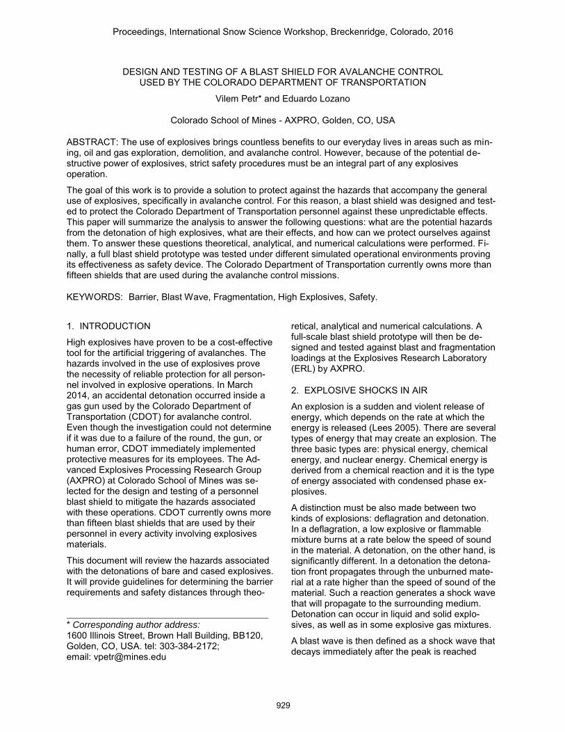
(Needham 2010). An explosion in air may cause widespread damage from the blast wave that it creates. Fig. 1 represents the typical overpres-sure versus time profile for a blast wave at a cer-tain distance from the source.
Fig. 1: Typical blast wave profile at a certain dis-
tance from the source.
The shock front of a blast wave is a determining factor in its behavior (Kinney et al. 1895). Depend-ing on the explosive charge geometry, different expanding shock wave shapes may be expected (i.e. planar, spherical, cylindrical, etc.).
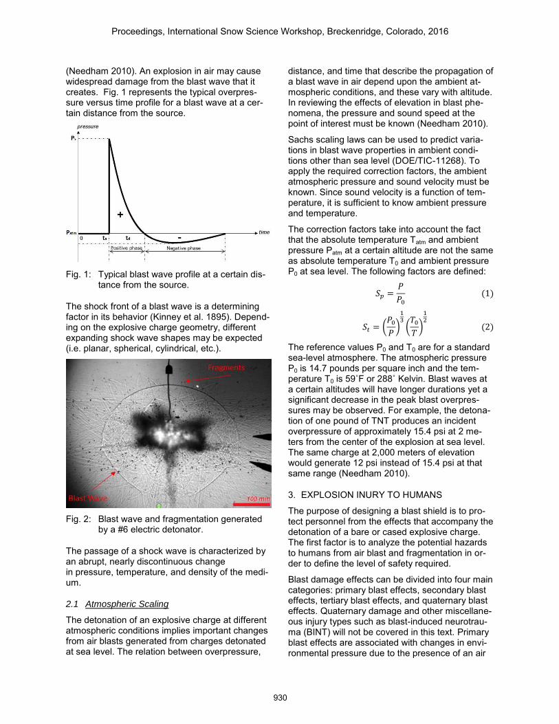
Fig. 2: Blast wave and fragmentation generated
by a #6 electric detonator.
The passage of a shock wave is characterized by an abrupt, nearly discontinuous change in pressure, temperature, and density of the medi-um.
2.1 Atmospheric Scaling
The detonation of an explosive charge at different atmospheric conditions implies important changes from air blasts generated from charges detonated at sea level. The relation between overpressure,
distance, and time that describe the propagation of a blast wave in air depend upon the ambient at-mospheric conditions, and these vary with altitude. In reviewing the effects of elevation in blast phe-nomena, the pressure and sound speed at the point of interest must be known (Needham 2010).
Sachs scaling laws can be used to predict varia-tions in blast wave properties in ambient condi-tions other than sea level (DOE/TIC-11268). To apply the required correction factors, the ambient atmospheric pressure and sound velocity must be known. Since sound velocity is a function of tem-perature, it is sufficient to know ambient pressure and temperature.
The correction factors take into account the fact that the absolute temperature Tatm and ambient pressure Patm at a certain altitude are not the same as absolute temperature T0 and ambient pressure P0 at sea level. The following factors are defined:
𝑆𝑝 =𝑃
𝑃0
(1)
𝑆𝑡 = (𝑃0
𝑃)
13
(𝑇0
𝑇)
12
(2)
The reference values P0 and T0 are for a standard sea-level atmosphere. The atmospheric pressure P0 is 14.7 pounds per square inch and the tem-perature T0 is 59˚F or 288˚ Kelvin. Blast waves at a certain altitudes will have longer durations yet a significant decrease in the peak blast overpres-sures may be observed. For example, the detona-tion of one pound of TNT produces an incident overpressure of approximately 15.4 psi at 2 me-ters from the center of the explosion at sea level. The same charge at 2,000 meters of elevation would generate 12 psi instead of 15.4 psi at that same range (Needham 2010).
3. EXPLOSION INURY TO HUMANS
The purpose of designing a blast shield is to pro-tect personnel from the effects that accompany the detonation of a bare or cased explosive charge. The first factor is to analyze the potential hazards to humans from air blast and fragmentation in or-der to define the level of safety required.
Blast damage effects can be divided into four main categories: primary blast effects, secondary blast effects, tertiary blast effects, and quaternary blast effects. Quaternary damage and other miscellane-ous injury types such as blast-induced neurotrau-ma (BINT) will not be covered in this text. Primary blast effects are associated with changes in envi-ronmental pressure due to the presence of an air
Proceedings, International Snow Science Workshop, Breckenridge, Colorado, 2016
930
blast. Humans are sensitive to the incident wave, reflected and dynamic overpressures, the rate of rise to peak overpressure after the arrival of the blast wave, the duration of such blast wave, and the specific impulse of the blast wave (DOE/TIC-11268). Tests have indicated that the air-containing tissues of the lungs can be considered as the critical target organ in blast overpressure injuries. The release of air bubbles from disrupted alveoli of the lungs into the vascular system likely accounts for most deaths. Typically, the lower the specific lung volume (lung volume/body mass), the more vulnerable the body is to shock.
A major health effect of unprotected noise expo-sure is permanent hearing loss. As with other air-filled organs, limits for eardrum rupture and tempo-rary threshold shift (TTS) are dependent on peak incident overpressure and duration. TTS usually abates within 48 hours but might last longer. Symptoms of TTS may include a temporary muf-fling of sound after hazardous exposure, a sensa-tion of fullness in the ear(s), tinnitus, and increased feelings of stress or fatigue (DOD 6055-9-STD). Temporary Threshold Shift (TTS) can be produced for peak values of about 0.2psi.
Secondary injuries are caused by fragments and other objects propelled by the explosion. Injuries to personnel due to fragment impact can be divid-ed into two categories, primary fragment and sec-ondary fragment injuries. Primary fragments are normally small, high-speed fragments that cause injury by penetration and perforation of vital areas of the body. Secondary fragments are normally larger and have less velocity upon impact and can cause non-penetrating blunt trauma (DOE/TIC-11268).
Another blast effect is bodily translation. Tertiary blast damage involves whole-body displacement and subsequent decelerating impacts due to the interaction of the human body with blast overpres-sures and impulses. Impact velocities fewer than 10 feet per second (11 km/h) are considered most-ly safe.
4. BARRIER DESIGN PARAMETERS
It is critical in the design of a personnel blast shield or any other barrier to consider all the pos-sible loads that it may be subjected to. This sec-tion will summarize the blast and fragmentation loading by using theoretical and empirical formula-tions. Then, a personnel blast shield will be de-signed in order to withstand such loads. Operational distances will be established depend-ing on the expected loads and required safety fac-
tor. Calculations for shields to protect personnel and equipment from blast and fragments are based on the total energy in the system to be shielded. That energy can be released as the overpressure in a blast wave and/or as the kinetic energy and momentum of a fragment (ME Design Safety Standards Manual 1994). Thermal loading will not be considered during this work as it is ex-pected to be the least restrictive.
4.1 Blast Loading Evaluation
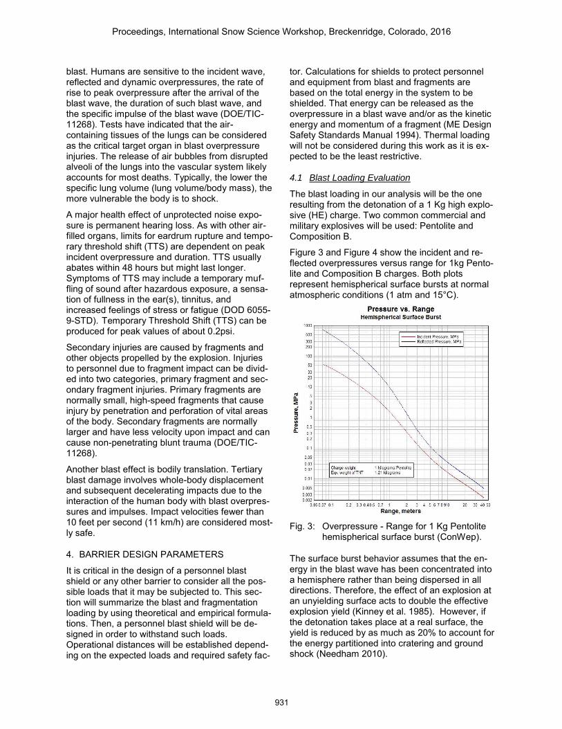
The blast loading in our analysis will be the one resulting from the detonation of a 1 Kg high explo-sive (HE) charge. Two common commercial and military explosives will be used: Pentolite and Composition B.
Figure 3 and Figure 4 show the incident and re-flected overpressures versus range for 1kg Pento-lite and Composition B charges. Both plots represent hemispherical surface bursts at normal atmospheric conditions (1 atm and 15°C).
Fig. 3: Overpressure - Range for 1 Kg Pentolite
hemispherical surface burst (ConWep).
The surface burst behavior assumes that the en-ergy in the blast wave has been concentrated into a hemisphere rather than being dispersed in all directions. Therefore, the effect of an explosion at an unyielding surface acts to double the effective explosion yield (Kinney et al. 1985). However, if the detonation takes place at a real surface, the yield is reduced by as much as 20% to account for the energy partitioned into cratering and ground shock (Needham 2010).
Proceedings, International Snow Science Workshop, Breckenridge, Colorado, 2016
931
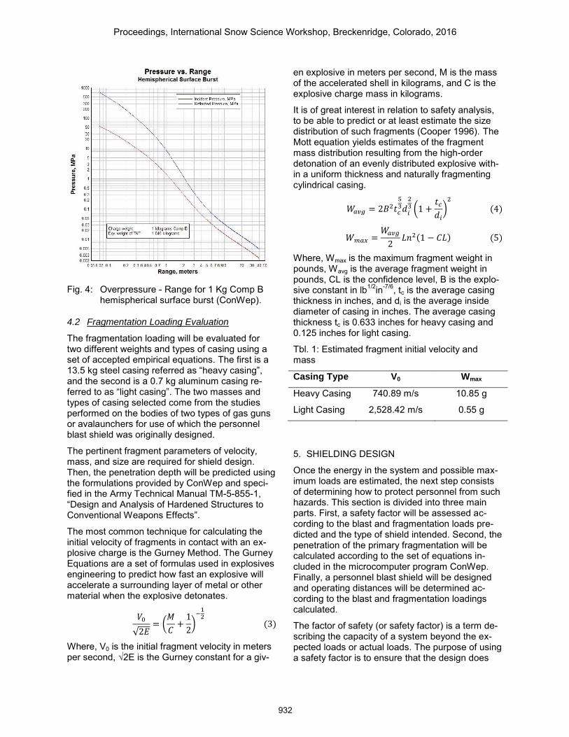
Fig. 4: Overpressure - Range for 1 Kg Comp B
hemispherical surface burst (ConWep).
4.2 Fragmentation Loading Evaluation
The fragmentation loading will be evaluated for two different weights and types of casing using a set of accepted empirical equations. The first is a 13.5 kg steel casing referred as “heavy casing”, and the second is a 0.7 kg aluminum casing re-ferred to as “light casing”. The two masses and types of casing selected come from the studies performed on the bodies of two types of gas guns or avalaunchers for use of which the personnel blast shield was originally designed.
The pertinent fragment parameters of velocity, mass, and size are required for shield design. Then, the penetration depth will be predicted using the formulations provided by ConWep and speci-fied in the Army Technical Manual TM-5-855-1, “Design and Analysis of Hardened Structures to Conventional Weapons Effects”.
The most common technique for calculating the initial velocity of fragments in contact with an ex-plosive charge is the Gurney Method. The Gurney Equations are a set of formulas used in explosives engineering to predict how fast an explosive will accelerate a surrounding layer of metal or other material when the explosive detonates.
𝑉0
√2𝐸= (
𝑀
𝐶+
1
2)
−12
(3)
Where, V0 is the initial fragment velocity in meters per second, √2E is the Gurney constant for a giv-
en explosive in meters per second, M is the mass of the accelerated shell in kilograms, and C is the explosive charge mass in kilograms.
It is of great interest in relation to safety analysis, to be able to predict or at least estimate the size distribution of such fragments (Cooper 1996). The Mott equation yields estimates of the fragment mass distribution resulting from the high-order detonation of an evenly distributed explosive with-in a uniform thickness and naturally fragmenting cylindrical casing.
𝑊𝑎𝑣𝑔 = 2𝐵2𝑡𝑐
53𝑑
𝑖
23 (1 +
𝑡𝑐
𝑑𝑖
)2
(4)
𝑊 𝑚𝑎𝑥 =𝑊𝑎𝑣𝑔
2𝐿𝑛2(1 − 𝐶𝐿) (5)
Where, Wmax is the maximum fragment weight in pounds, Wavg is the average fragment weight in pounds, CL is the confidence level, B is the explo-sive constant in lb1/2in-7/6, tc is the average casing thickness in inches, and di is the average inside diameter of casing in inches. The average casing thickness tc is 0.633 inches for heavy casing and 0.125 inches for light casing.
Tbl. 1: Estimated fragment initial velocity and mass
Casing Type V0 Wmax
Heavy Casing 740.89 m/s 10.85 g
Light Casing 2,528.42 m/s 0.55 g
5. SHIELDING DESIGN
Once the energy in the system and possible max-imum loads are estimated, the next step consists of determining how to protect personnel from such hazards. This section is divided into three main parts. First, a safety factor will be assessed ac-cording to the blast and fragmentation loads pre-dicted and the type of shield intended. Second, the penetration of the primary fragmentation will be calculated according to the set of equations in-cluded in the microcomputer program ConWep. Finally, a personnel blast shield will be designed and operating distances will be determined ac-cording to the blast and fragmentation loadings calculated.
The factor of safety (or safety factor) is a term de-scribing the capacity of a system beyond the ex-pected loads or actual loads. The purpose of using a safety factor is to ensure that the design does
Proceedings, International Snow Science Workshop, Breckenridge, Colorado, 2016
932
not fail in the event of unexpectedly high loads or the presence of material defects. The criteria on how to estimate the final safety factor are given in Ullman (1992). The resultant factor of safety is:
SF =Blast Shield Thickness
Fragment Penetration= 1.98 ≈ 2 (6)
Considering this value and according to the defini-tion of factor of safety, the shield thickness must be at least two times the fragment penetration depth.
Barrier thickness requirements are found based on fragment penetration that, for this work, will be the most restrictive criteria. Fragment penetration is calculated using the microcomputer program ConWep. Penetration-range curves are obtained depending on fragment mass, fragment initial ve-locity and impacted material. For design purposes, homogeneous hardened steel is chosen as the primary shield material.
In order to determine how far a uniform hardened steel barrier must be placed, the shield prototype thickness must be defined. In this case, since one of the intended features of this personnel blast shield is mobility, the weight of the structure is fac-tor to consider. For this reason, a standard plate thickness of ½ inch (12.7 mm) is selected due to its relatively low weight and easy replacement in case of damage. From the adopted barrier thick-ness and the factor of safety of 2 calculated, a maximum penetration of ¼ inch (6.35 mm) is de-fined as the threshold for the personnel blast shield.
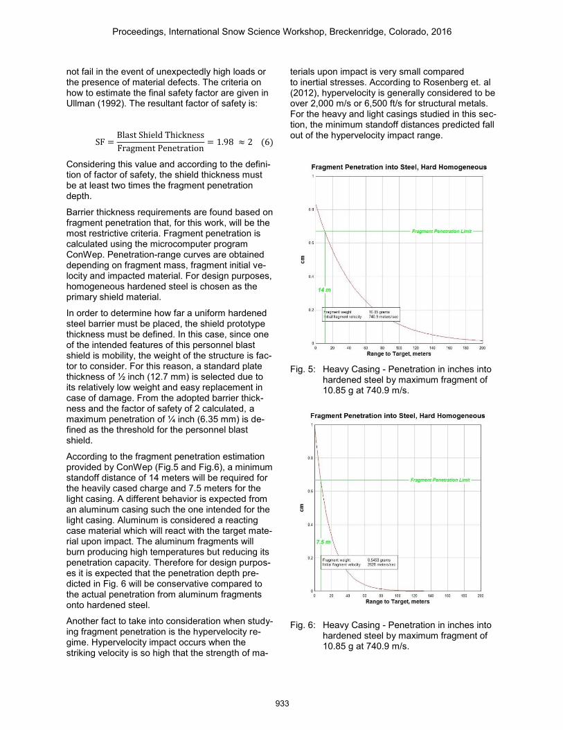
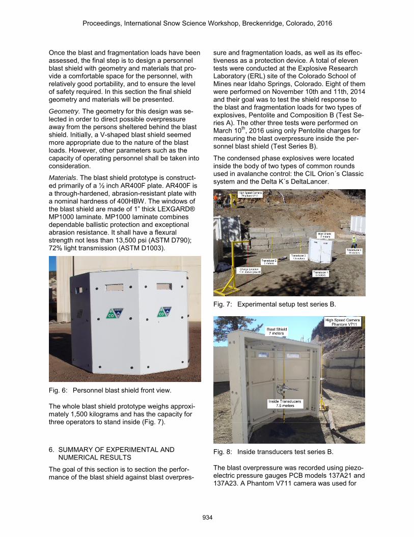
According to the fragment penetration estimation provided by ConWep (Fig.5 and Fig.6), a minimum standoff distance of 14 meters will be required for the heavily cased charge and 7.5 meters for the light casing. A different behavior is expected from an aluminum casing such the one intended for the light casing. Aluminum is considered a reacting case material which will react with the target mate-rial upon impact. The aluminum fragments will burn producing high temperatures but reducing its penetration capacity. Therefore for design purpos-es it is expected that the penetration depth pre-dicted in Fig. 6 will be conservative compared to the actual penetration from aluminum fragments onto hardened steel.
Another fact to take into consideration when study-ing fragment penetration is the hypervelocity re-gime. Hypervelocity impact occurs when the striking velocity is so high that the strength of ma-
terials upon impact is very small compared to inertial stresses. According to Rosenberg et. al (2012), hypervelocity is generally considered to be over 2,000 m/s or 6,500 ft/s for structural metals. For the heavy and light casings studied in this sec-tion, the minimum standoff distances predicted fall out of the hypervelocity impact range.
Fig. 5: Heavy Casing - Penetration in inches into
hardened steel by maximum fragment of 10.85 g at 740.9 m/s.
Fig. 6: Heavy Casing - Penetration in inches into hardened steel by maximum fragment of 10.85 g at 740.9 m/s.
Proceedings, International Snow Science Workshop, Breckenridge, Colorado, 2016
933
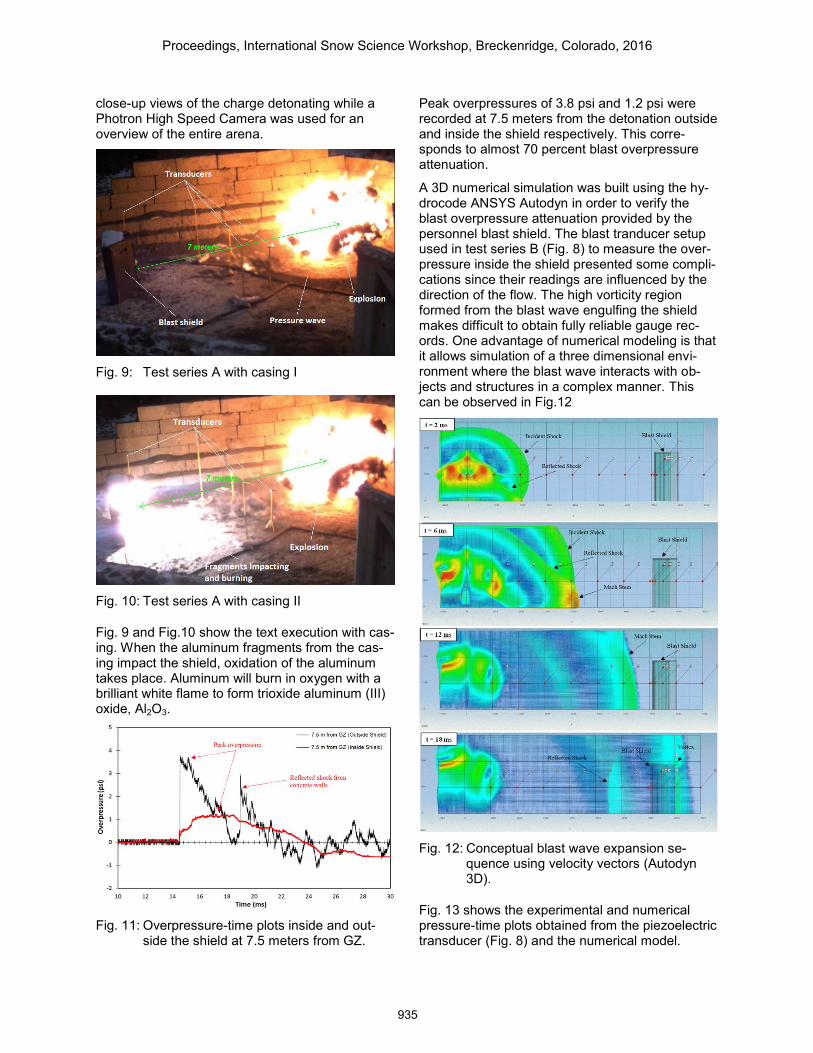
Once the blast and fragmentation loads have been assessed, the final step is to design a personnel blast shield with geometry and materials that pro-vide a comfortable space for the personnel, with relatively good portability, and to ensure the level of safety required. In this section the final shield geometry and materials will be presented.
Geometry. The geometry for this design was se-lected in order to direct possible overpressure away from the persons sheltered behind the blast shield. Initially, a V-shaped blast shield seemed more appropriate due to the nature of the blast loads. However, other parameters such as the capacity of operating personnel shall be taken into consideration.
Materials. The blast shield prototype is construct-ed primarily of a ½ inch AR400F plate. AR400F is a through-hardened, abrasion-resistant plate with a nominal hardness of 400HBW. The windows of the blast shield are made of 1” thick LEXGARD® MP1000 laminate. MP1000 laminate combines dependable ballistic protection and exceptional abrasion resistance. It shall have a flexural strength not less than 13,500 psi (ASTM D790); 72% light transmission (ASTM D1003).
Fig. 6: Personnel blast shield front view.
The whole blast shield prototype weighs approxi-mately 1,500 kilograms and has the capacity for three operators to stand inside (Fig. 7).
6. SUMMARY OF EXPERIMENTAL AND NUMERICAL RESULTS
The goal of this section is to section the perfor-mance of the blast shield against blast overpres-
sure and fragmentation loads, as well as its effec-tiveness as a protection device. A total of eleven tests were conducted at the Explosive Research Laboratory (ERL) site of the Colorado School of Mines near Idaho Springs, Colorado. Eight of them were performed on November 10th and 11th, 2014 and their goal was to test the shield response to the blast and fragmentation loads for two types of explosives, Pentolite and Composition B (Test Se-ries A). The other three tests were performed on March 10th, 2016 using only Pentolite charges for measuring the blast overpressure inside the per-sonnel blast shield (Test Series B).
The condensed phase explosives were located inside the body of two types of common rounds used in avalanche control: the CIL Orion´s Classic system and the Delta K´s DeltaLancer.
Fig. 7: Experimental setup test series B.
Fig. 8: Inside transducers test series B.
The blast overpressure was recorded using piezo-electric pressure gauges PCB models 137A21 and 137A23. A Phantom V711 camera was used for
Proceedings, International Snow Science Workshop, Breckenridge, Colorado, 2016
934
close-up views of the charge detonating while a Photron High Speed Camera was used for an overview of the entire arena.
Fig. 9: Test series A with casing I
Fig. 10: Test series A with casing II
Fig. 9 and Fig.10 show the text execution with cas-ing. When the aluminum fragments from the cas-ing impact the shield, oxidation of the aluminum takes place. Aluminum will burn in oxygen with a brilliant white flame to form trioxide aluminum (III) oxide, Al2O3.
Fig. 11: Overpressure-time plots inside and out-
side the shield at 7.5 meters from GZ.
Peak overpressures of 3.8 psi and 1.2 psi were recorded at 7.5 meters from the detonation outside and inside the shield respectively. This corre-sponds to almost 70 percent blast overpressure attenuation.
A 3D numerical simulation was built using the hy-drocode ANSYS Autodyn in order to verify the blast overpressure attenuation provided by the personnel blast shield. The blast tranducer setup used in test series B (Fig. 8) to measure the over-pressure inside the shield presented some compli-cations since their readings are influenced by the direction of the flow. The high vorticity region formed from the blast wave engulfing the shield makes difficult to obtain fully reliable gauge rec-ords. One advantage of numerical modeling is that it allows simulation of a three dimensional envi-ronment where the blast wave interacts with ob-jects and structures in a complex manner. This can be observed in Fig.12
Fig. 12: Conceptual blast wave expansion se-
quence using velocity vectors (Autodyn 3D).
Fig. 13 shows the experimental and numerical pressure-time plots obtained from the piezoelectric transducer (Fig. 8) and the numerical model.
Proceedings, International Snow Science Workshop, Breckenridge, Colorado, 2016
935
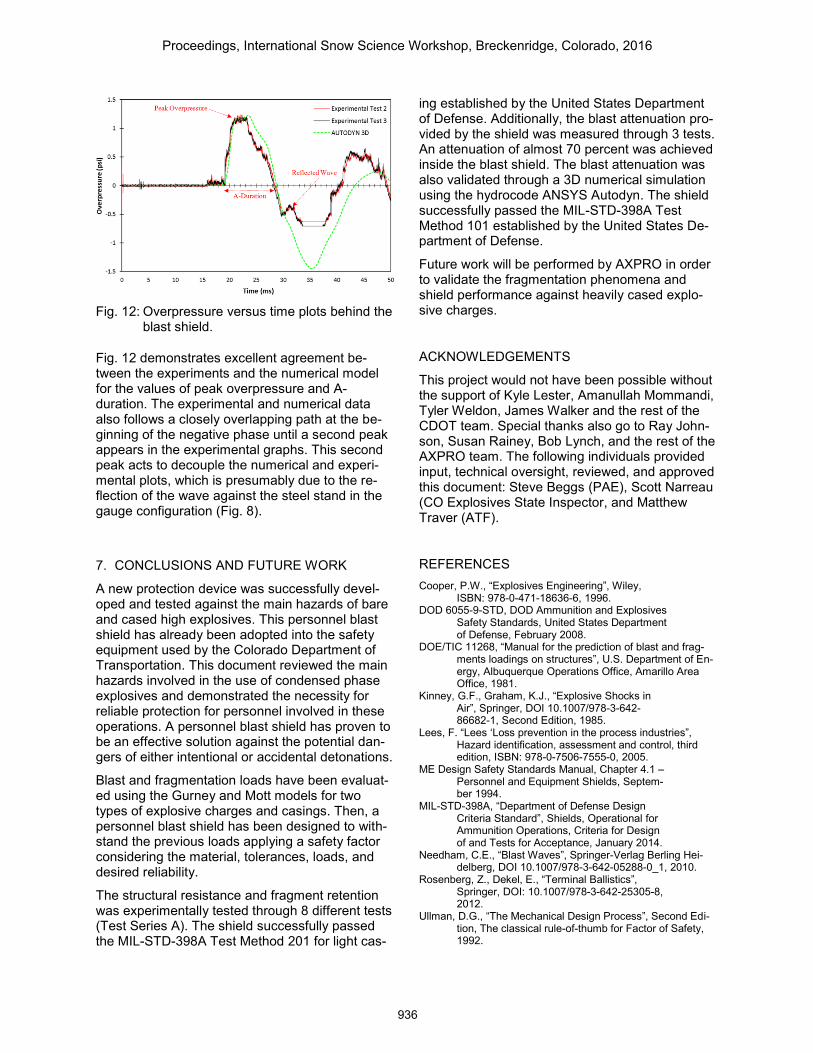
Fig. 12: Overpressure versus time plots behind the
blast shield.
Fig. 12 demonstrates excellent agreement be-tween the experiments and the numerical model for the values of peak overpressure and A-duration. The experimental and numerical data also follows a closely overlapping path at the be-ginning of the negative phase until a second peak appears in the experimental graphs. This second peak acts to decouple the numerical and experi-mental plots, which is presumably due to the re-flection of the wave against the steel stand in the gauge configuration (Fig. 8).
7. CONCLUSIONS AND FUTURE WORK
A new protection device was successfully devel-oped and tested against the main hazards of bare and cased high explosives. This personnel blast shield has already been adopted into the safety equipment used by the Colorado Department of Transportation. This document reviewed the main hazards involved in the use of condensed phase explosives and demonstrated the necessity for reliable protection for personnel involved in these operations. A personnel blast shield has proven to be an effective solution against the potential dan-gers of either intentional or accidental detonations.
Blast and fragmentation loads have been evaluat-ed using the Gurney and Mott models for two types of explosive charges and casings. Then, a personnel blast shield has been designed to with-stand the previous loads applying a safety factor considering the material, tolerances, loads, and desired reliability.
The structural resistance and fragment retention was experimentally tested through 8 different tests (Test Series A). The shield successfully passed the MIL-STD-398A Test Method 201 for light cas-
ing established by the United States Department of Defense. Additionally, the blast attenuation pro-vided by the shield was measured through 3 tests. An attenuation of almost 70 percent was achieved inside the blast shield. The blast attenuation was also validated through a 3D numerical simulation using the hydrocode ANSYS Autodyn. The shield successfully passed the MIL-STD-398A Test Method 101 established by the United States De-partment of Defense.
Future work will be performed by AXPRO in order to validate the fragmentation phenomena and shield performance against heavily cased explo-sive charges.
ACKNOWLEDGEMENTS
This project would not have been possible without the support of Kyle Lester, Amanullah Mommandi, Tyler Weldon, James Walker and the rest of the CDOT team. Special thanks also go to Ray John-son, Susan Rainey, Bob Lynch, and the rest of the AXPRO team. The following individuals provided input, technical oversight, reviewed, and approved this document: Steve Beggs (PAE), Scott Narreau (CO Explosives State Inspector, and Matthew Traver (ATF).
REFERENCES Cooper, P.W., “Explosives Engineering”, Wiley,
ISBN: 978-0-471-18636-6, 1996. DOD 6055-9-STD, DOD Ammunition and Explosives
Safety Standards, United States Department of Defense, February 2008.
DOE/TIC 11268, “Manual for the prediction of blast and frag-ments loadings on structures”, U.S. Department of En-ergy, Albuquerque Operations Office, Amarillo Area Office, 1981.
Kinney, G.F., Graham, K.J., “Explosive Shocks in Air”, Springer, DOI 10.1007/978-3-642-86682-1, Second Edition, 1985.
Lees, F. “Lees ‘Loss prevention in the process industries”, Hazard identification, assessment and control, third edition, ISBN: 978-0-7506-7555-0, 2005.
ME Design Safety Standards Manual, Chapter 4.1 – Personnel and Equipment Shields, Septem-ber 1994.
MIL-STD-398A, “Department of Defense Design Criteria Standard”, Shields, Operational for Ammunition Operations, Criteria for Design of and Tests for Acceptance, January 2014.
Needham, C.E., “Blast Waves”, Springer-Verlag Berling Hei-delberg, DOI 10.1007/978-3-642-05288-0_1, 2010.
Rosenberg, Z., Dekel, E., “Terminal Ballistics”, Springer, DOI: 10.1007/978-3-642-25305-8, 2012.
Ullman, D.G., “The Mechanical Design Process”, Second Edi-tion, The classical rule-of-thumb for Factor of Safety, 1992.
Proceedings, International Snow Science Workshop, Breckenridge, Colorado, 2016
936