design and simulation of mobile cnc machine; based tripod
TRANSCRIPT

114
PORT SAID ENGINEERING RESEARCH JOURNAL
Faculty of Engineering - Port Said University
Volume 25 No. 1 March 2021 pp.114-127
(Production Engineering & Mechanical Design)
Design and Simulation of Mobile CNC Machine;
Based Tripod Stewart Platform
Mohamed A.O. Elamirali1, Elmoushi Elsayed 2, Sabreen A. Abdelwahab 3
Received: 5 October 2020; Accepted: 4 January 2021
ABSTRACT
This paper presents the design model for inverse kinematics Stewart tricept platform as a parallel structure robot which has
three fixed prismatic actuators. The portable robot showed fast, consistent and solid structure which recommended to portable Computer Numerically Controlled (CNC) machine that can easily be moved to large parts and perform various
operations. The mechanism has 3 degrees of freedom and the 3D model has been built in Solidworks both for design and
performance simulation purposes. An exact, analytical geometry method for determining the inverse kinematics solution of a parallel kinematic mobile structure is developed. Machine control elements performance was checked using Simulink
and MATLAB software. The proposed parallel manipulator shows better orientation capability and is very meaningful to
the development of the multi axes hybrid machine tools.
Keywords: Stewart platform; Cost effective design; Portable CNC machines; Robot forward and inverse kinematics.
1. INTRODUCTION
It is obvious that machining large components as aerospace
and shipping industry, power plants…etc. need to build
larger long travels machine. Large rotation and slide
movements would be too heavy to be moved and machined
precisely. Constructing large machines leads to problems
such as lower static and dynamic rigidity, static deflection,
high cost of structure-transport-energy, and less accuracy.
Manufacturing issues like handling, and machining large
parts possess a great impact in time than in size. So, these
topics need new research solutions. The evolution from
specific task to multi-task machines is increasing, this
drives movable machines [1] towards robotics [2], i.e.,
intelligent machines.
1.1. Paper structure
This paper is divided into eight sections, the first is the
introduction section, and the second is the literature review
section. The third section presents the proposed
mechanical design of portable CNC machine and working
principal, while the fourth section illustrates the
mechanism design in Solidworks. The fifth section.
introduces a solution to the reverse kinematics problem
of the mechanism, where section six shows the Simulink
model development and dynamics simulation. Section
seven displays the mechanism prototype and control
circuit, and section eight draws the conclusions, which is
followed by the references.
2. LITERATURE REVIEW
2.1. Design concept
In the past two decades, Parallel Kinematic Machines,
Stewart platforms have attracted increasing attention. Each
actuated leg has to carry only part of the payload: this is
quite energy efficient and allows supporting heavy loads.
The parallel structure can reach highly dynamic motions
that the end-effector moves. A major problem in practice
is the need for spherical joints with a very large angular
range and sufficient stiffness at the same time.
In reality, Parallel Kinematic Machines (PKM) lose
stiffness at support and link joints which leads to lower
dynamics than expected. As motion in three axes is a big
challenge. A study of the potentials of PKM compared to
classical serial Kinematic Machines (KM) centers was
provided by Tlusty [3]. Weck [4] discussed an expanded
review of few successful industrial applications of PKM.
Combined KM have been used to get good workspace and
dynamic behavior. In manufacturing market, a successful
solution is the Tricept [5], (Figure 1). It has many machine
tools, which combine three parallel axes and two serial
rotary axes developing a 5-axes machine. Compared with
serial or parallel KM, hybrid combined machine have the
advantages of high stiffness, high speed, large workspace,
and heterogeneous surface processing ability. Zhang [6]
presents a novel parallel machine with one translational
1Researcher, Department of Production Technology, Helwan University, Saray El-Quba, 11281, Cairo, Egypt, email:
2Assistant professor, Department of Production Technology, Helwan University, Saray El-Quba, 11281, Cairo, Egypt, email:
3Assistant professor, Department of Production Technology,
Helwan University, Saray El-Quba, 11281, Cairo, Egypt, email: [email protected]
DOI: 10.21608/pserj.2021.43738.1063
115
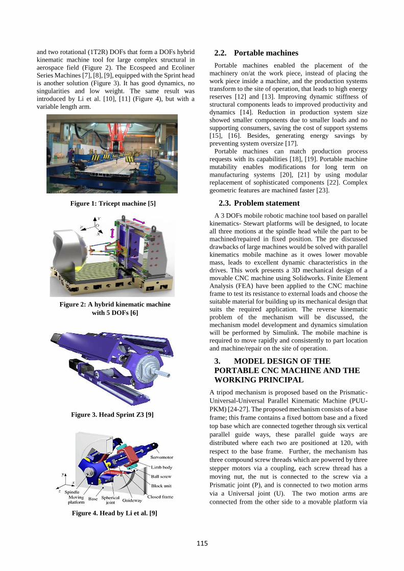
and two rotational (1T2R) DOFs that form a DOFs hybrid
kinematic machine tool for large complex structural in
aerospace field (Figure 2). The Ecospeed and Ecoliner
Series Machines [7], [8], [9], equipped with the Sprint head
is another solution (Figure 3). It has good dynamics, no
singularities and low weight. The same result was
introduced by Li et al. [10], [11] (Figure 4), but with a
variable length arm.
2.2. Portable machines
Portable machines enabled the placement of the
machinery on/at the work piece, instead of placing the
work piece inside a machine, and the production systems
transform to the site of operation, that leads to high energy
reserves [12] and [13]. Improving dynamic stiffness of
structural components leads to improved productivity and
dynamics [14]. Reduction in production system size
showed smaller components due to smaller loads and no
supporting consumers, saving the cost of support systems
[15], [16]. Besides, generating energy savings by
preventing system oversize [17].
Portable machines can match production process
requests with its capabilities [18], [19]. Portable machine
mutability enables modifications for long term on
manufacturing systems [20], [21] by using modular
replacement of sophisticated components [22]. Complex
geometric features are machined faster [23].
2.3. Problem statement
A 3 DOFs mobile robotic machine tool based on parallel
kinematics- Stewart platforms will be designed, to locate
all three motions at the spindle head while the part to be
machined/repaired in fixed position. The pre discussed
drawbacks of large machines would be solved with parallel
kinematics mobile machine as it owes lower movable
mass, leads to excellent dynamic characteristics in the
drives. This work presents a 3D mechanical design of a
movable CNC machine using Solidworks. Finite Element
Analysis (FEA) have been applied to the CNC machine
frame to test its resistance to external loads and choose the
suitable material for building up its mechanical design that
suits the required application. The reverse kinematic
problem of the mechanism will be discussed, the
mechanism model development and dynamics simulation
will be performed by Simulink. The mobile machine is
required to move rapidly and consistently to part location
and machine/repair on the site of operation.
3. MODEL DESIGN OF THE
PORTABLE CNC MACHINE AND THE
WORKING PRINCIPAL
A tripod mechanism is proposed based on the Prismatic-
Universal-Universal Parallel Kinematic Machine (PUU-
PKM) [24-27]. The proposed mechanism consists of a base
frame; this frame contains a fixed bottom base and a fixed
top base which are connected together through six vertical
parallel guide ways, these parallel guide ways are
distributed where each two are positioned at 120ₒ with
respect to the base frame. Further, the mechanism has
three compound screw threads which are powered by three
stepper motors via a coupling, each screw thread has a
moving nut, the nut is connected to the screw via a
Prismatic joint (P), and is connected to two motion arms
via a Universal joint (U). The two motion arms are
connected from the other side to a movable platform via
Figure 1: Tricept machine [5]
Figure 2: A hybrid kinematic machine
with 5 DOFs [6]
Figure 3. Head Sprint Z3 [9]
Figure 4. Head by Li et al. [9]

116
another U joint. Hence, this movable platform can have
different motion paths in X, Y, and Z directions.
The purpose of the mechanism is to move the movable
platform in the three axes of motion (X, Y, and Z).
Through controlling the operation of the stepper motors in
terms of rotational speed and direction of rotation, the
motion is transmitted from the motor to the screw thread
via a coupling, the screw thread converts the motion from
rotational to linear motion by moving the nut, which moves
a linear distance equals to 1.5 mm when the screw thread
turns one revolution (pitch), then the motion is transmitted
to the movable platform through the motion arms and the
two U joints. The main parts of the mechanism are shown
in Figure 5, where Figure 5(a) presents a schematic
diagram. Figure 5(b) shows the U joint details.
4. Mechanism design in Solidworks 4.1. Solidworks outline
Design programs such as (Solidworks, Solid edge, NX
(Unigraphics), Pro engineer, inventor, CATIA, etc.), are
widely spread because of ease of use, availability, and
scheduling of raw materials that are useful in design and
the many features that they have. Solidworks is used in
designing and simulating mechanical systems [28], it
enables creators to outline out thoughts, explore different
avenues regarding highlights, and 3D model production. It
starts with paper sketches followed by Solidworks
environment to construct the parts and assemble them
together. 2D drawings are the last stage then the design can
be sent to be manufactured. These significant stages are
shown in Figure 6 [29], [30].
4.2. Three-dimensional mechanism designation
Planning steps are following the stream outline in Figure
6. As a matter of first importance, choosing the elements
of each part to turn out with appropriate design area. Then,
demonstrating the parts separately, this developed
mechanism is separated to three main group; Main frame
(fixed bottom base, fixed top base, and vertical pillars), the
screw drive group (stepper motor, coupling, screw drive,
moving nut), and the movable platform group (movable
platform, and motion arms with two U joints), Figure 7(a)
shows the main groups of the structure. Subsequent stage
is to consolidate parts to manufacture the last structure. A
down-up strategy is utilized, which begins by building the
parts and joining them. Figure 7(b) presents structure
assembly.
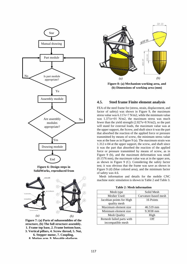
4.3. Working area and dimensions
Dimensions of the mechanism are proposed based on the
operating dimensions of portable CNC machines that
depends on the required working area, so that the
movement of the table should cover the required space
based on the required function. The working area is the
area in which the machine can reach and operates. After
completing the design in the Solidworks, the machine
performance was tested to ensure that the required work
area can be covered, as shown in Figure 8. From
workspace results of the experimental tests on the
Solidworks program, it can be noted that the model of the
Portable CNC machine as shown in Figure 8 can work in a
specific area that cannot be bypassed. In this area the
machine can perform any type of operation such as (hole,
formation of any path or opening of the sewerage ... etc.).
4.4. Finite element analysis
Static analysis was employed on the frame of the mobile
CNC machine to check its ability to stand under the
working loads such as the cutting force. Stress, strain,
displacement, and factor of safety were checked for Steel
and Aluminum materials. Table 1 shows the materials
specifications. The following procedures were followed to
check from not to collapse, the installations were
performed in three green locations, the loading area was
the moving table, which is the mounting area for the tools
(purple locations), as shown in Figure 9. The Steel frame
mass was about 16.5 kg, while the aluminum frame mass
was 5.641Kg. An external weight of 60 kg is applied to
frame through the static analysis.
Table 1: Material specifications [31], [32]
Property Unit AISI 1035
Steel (SS) Aluminum
1060 Alloy
Elastic
Modulus N/m2 2.05e+11 6.9e+10
Poisson's
Ratio N/A 0.29 0.33
Shear
Modulus N/m2 8e+10 2.7e+10
Mass Density Kg/m3 7850 2700
Tensile
Strength N/m2 585000003 68935600
Yield
Strength N/m2 282685049 27574200
Thermal
Expansion
Coefficient K 1.1e-05 2.4e-05
Thermal
Conductivity W/(m·K) 52 200
Specific Heat J/(kg·K) 486 900
Figure 5: (a) Schematic diagram of the
proposed mechanism, (b) U joint.
1. Frame top base, 2. Frame bottom base, 3.
Vertical parallel guide ways, 4. Screw thread,
5. Nut, 6. Stepper motor, 7. Coupling, 8.
Movement arm, 9. Movable platform.
(b) (a)
117
4.5. Steel frame Finite element analysis
FEA of the steel frame for (stress, strain, displacement, and
factor of safety) was shown in Figure 9, the maximum
stress value was 6.117e+7 N/m2, while the minimum value
was 1.371e+01 N/m2, the maximum stress was much
fewer than the yield strength (2.827e+8 N/m2), so the part
will stand for external loads, the maximum value was at
the upper support, the Screw, and shaft since it was the part
that absorbed the reaction of the applied force or pressure
transmitted by means of screw, the minimum stress value
was at the base as in Figure 9 (a). The maximum strain was
1.312 e-04 at the upper support, the screw, and shaft since
it was the part that absorbed the reaction of the applied
force or pressure transmitted by means of screw, as in
Figure 9 (b), and the maximum deformation was small
(0.1576 mm), the maximum value was at in the upper arm,
as shown in Figure 9 (C). Considering the safety factor
test; it was obvious that the frame was save as shown in
Figure 9 (d) (blue colored area), and the minimum factor
of safety was 4.6.
Mesh information and details for the mobile CNC
machine static simulation is shown in Table 2 and Table 3.
Table 2: Mesh information
Mesh type Solid Mesh
Mesher Used: Curvature-based mesh
Jacobian points for High
quality mesh
16 Points
Maximum element size 46.519 mm
Minimum element size 9.3038 mm
Mesh Quality High
Remesh failed parts with
incompatible mesh
Off
Yes
No
Ye
s
No Is part module
appropriate?
Star
Manual drawing
Part module
Assembly module
Are assembly
modules
appropriate?
Drawing module
End
Figure 6: Design steps in
SolidWorks, reproduced from
[30]
(a)
Figure 7: (a) Parts of subassemblies of the
structure, (b) The full structure assembly.
1. Frame top base, 2. Frame bottom base,
3. Vertical pillars, 4. Screw thread, 5. Nut,
6. Stepper motor, 7. Coupling,
8. Motion arm, 9. Movable platform.
(b)
(a) (b)
Figure 8: (a) Mechanism working area, and
(b) Dimensions of working area (mm)

118
Figure 9: Steel (a) Stress test, (b) Strain test, (c)
Displacement test, and (d) Factor of safety test.
Table 3: Mesh information - Details
Total Nodes 222198
Total Elements 113011
Maximum Aspect Ratio 1,397.2
% of elements with Aspect Ratio < 3 34.8
% of elements with Aspect Ratio > 10 8.24
% of distorted elements (Jacobian) 0
4.6. Aluminum frame Finite element analysis
FEA of the Aluminium frame for (stress, strain,
displacement, and factor of safety) was shown in Figure
10, the maximum stress value was 5.868 e+7 N/m2, while
the minimum value was 1.371e+01 N/m2, the maximum
stress was higher than the yield strength (2.757e+7 N/m2),
so the part will not stand for external loads, the maximum
value was at the upper support, the Screw, and shaft since
it was the part that absorbed the reaction of the applied
force or pressure transmitted by means of screw, the
minimum stress value was at the base as in Figure 10 (a).
The maximum strain was 3.99 e-04 at the upper support,
the screw, and shaft since it was the part that absorbed the
reaction of the applied force or pressure transmitted by
means of screw, as in Figure 10 (b), and the maximum
deformation was large (0.467 mm), the maximum value
was at in the upper arm, as shown in Figure 10 (C).
Considering the safety factor test; it was obvious that the
frame was unsafe as shown in Figure 10 (d) (red colored
area), and the minimum factor of safety was 0.47 that is
less than one, meaning that Aluminum frame design is
unsafe.
Mesh information and details for the mobile CNC
machine static simulation is shown in Table 4 and Table 5.
(a)
(b)
(c)
(d)
(a)

119
Figure 10: Aluminum: (a) Stress test, (b) Strain
test, (c) Displacement test, (d) Factor of safety test
Table 4: Mesh information
Mesh type Solid Mesh
Mesher Used: Curvature-based mesh
Jacobian points for High
quality mesh
16 Points
Maximum element size 46.519 mm
Minimum element size 9.3038 mm
Mesh Quality High
Remesh failed parts with
incompatible mesh
Off
Table 5: Mesh information - Details
Total Nodes 222198
Total Elements 113011
Maximum Aspect Ratio 1,397.2
% of elements with Aspect Ratio < 3 34.8
% of elements with Aspect Ratio > 10 8.24
% of distorted elements (Jacobian) 0
4.7. Material selection
In addition to failure of Aluminum frame in some points,
and the maximum stress is nearly the same in both cases of
Steel and Aluminum, but the yield strength and factor of
safety are much higher in Steel case compared to
Aluminum case. However, the strain and deformation
values under the same load are much smaller in case of
Steel as well. Hence, Steel material is selected.
5. THE REVERSE KINEMATICS
PROBLEM
Parallel manipulators are often classified according to the
number of connections between the fixed bottom (base)
and the upper platform. In this model the base (link1) and
the platform (link2) are connected by means of 6
intermediate links (a2, a3), all links connected together by
means of 6 universal joints each has 2 DOF and 3 prismatic
joints, each has 1 DOF with independent joint constraints.
The model degree of freedom then can be calculated using
Grubler’s formula which results model DOF equal to 3 as
in equation (1).
DOFs = m (N-1-J) + ∑ 𝑓𝑖𝐽𝑖=1 (1)
Where
N: # of links including ground,
J: # of joints,
m=6 for spatial bodies,
f: # of freedoms allowed by joints.
Parallel manipulator almost faces trivial problems in
inverse kinematics analysis and is much easier than
forward kinematics. The reverse kinematics relations for a
3DOF machine platform can be mathematically
formulated in several ways. Every representation of the
problem can have its advantages and disadvantages which
become emphasized when a different optimization
algorithm is applied. The inverse kinematics solution in
this work is based on the determination of the structural
parameters of the parallel manipulator, when the position
and orientation of the movable platform are given to solve
the input displacement of the prismatic joints.
The most common set of parameters in inverse kinematics
are: joint position vectors on base and mobile platform (𝑎1⃑⃑⃑⃑
and 𝑏⃑⃑ ), translation vectors between base and mobile
systems (𝑆 ⃑⃑⃑ and �⃑� ), radii of fixed and movable platforms
(R, r), distance between closes parallel guide ways (𝑎2 and
𝑎3), joint placement defined with no rotation angle
between joints for both platforms Figure 11 and joint
(b)
(c)
(d)

120
moving area (𝑅10 = I, unit matrix). From those values are
then calculated values for joints movable leg length (motor
element) 𝑆1⃑⃑⃑⃑ which are used in calculations to control the
position of movable end effector (tool) that placed on
mobile platform above the geometrical center of joints at
required X1, Y1 and Z1 position (see equations (2), (3) and
(4)).
End effector (tool) is placed on mobile platform above the
geometrical center of joints placed on that platform by
height tool. Therefore, the inverse position kinematics
solves the input tool position variables �⃑� = [x1, y1, z1]
from a given output actuated motor position value 𝑆 ⃑⃑⃑ .
𝑆1⃑⃑⃑⃑ + 𝑆 ⃑⃑⃑ = 𝑎2⃑⃑⃑⃑ + 𝑎3⃑⃑⃑⃑ (2)
𝑎1⃑⃑⃑⃑ + 𝑆 ⃑⃑⃑ = �⃑� + 𝑅10 𝑏⃑⃑ (3)
From (2) and (3);
𝑆1⃑⃑⃑⃑ = − �⃑� − 𝑅10 𝑏⃑⃑ + ( 𝑎1⃑⃑⃑⃑ + 𝑎2⃑⃑⃑⃑ + 𝑎3⃑⃑⃑⃑ ) (4)
Where,
𝑎1⃑⃑⃑⃑ = [ R 0 0] T,
𝑎2⃑⃑⃑⃑ = [ (R- 𝑎2) -R 0 0] T,
𝑎3⃑⃑⃑⃑ = [ ((x1+r sin30) - (R- 𝑎2)) (y1 - yc) 0] T,
�⃑� = [ x1 y1 z1] T,
𝑏⃑⃑ = [(x1+r) y1 0] T,
𝑅10 = I, unit matrix
Python software was applied to some computational
relationships for different platform planner positions �⃑� and
program was worked correctly (Figure 12, and 13).
The change in the movable leg length (motor element)
∆ 𝑆1 can be calculated as;
∆ 𝑆1 = 𝑁 ∗ 𝑃 (5)
Where,
𝑁:Number of motor revolutions in minutes (rev/min).
𝑃: Thread pitch (mm).
Then the movable platform position can be controlled
based on the change in movable leg length ∆ 𝑆1, or motor
rev/min, or motor input torque τ, as motor torque is a
function in motor revolution per minutes.
6. SIMULINK MODEL
DEVELOPMENT AND DYNAMICS
SIMULATION
Simulink® is a software package for modeling, simulating,
and analyzing dynamic systems. It supports linear and
nonlinear systems, modeled in continuous time, sampled
Figure 11: Inverse kinematics vectors
analysis geometric parameters.
Figure 12: Python software program output
results for movable leg length 𝑺𝟏⃑⃑⃑⃑⃑⃑ .
Figure 13: Python software program for
movable leg length 𝑺𝟏⃑⃑⃑⃑ ⃑ calculation on the basis
of joint parameters.

121
time, or a hybrid of the two. Systems can also be multi-
rate, i.e., have different parts that are sampled or updated
at different rates. Simulations are interactive, and an
instant access to all the analysis tools in MATLAB® is
available, so the results can be analyzed and visualized
immediately. Simulink is also practical as modeling and
solving real problems can take place. Simulink is a well
tool for model-based design [33].
6.1. Simulink model
The developed mechanism in Solidworks in this work is
transferred into Simulink software in the form of Simulink
model that contains blocks, in order to perform simulation
for design verification. The blocks imported to the
Simulink were rearranged according to the engineering
laws, the physical laws, and the required assembly. The
Simulink model contains three blocks; these are the inputs,
the system, and the outputs blocks. The input block shows
three inputs; these are the torque required to power each
screw thread. The output block represents the three outputs
value which are the X, Y, and Z position of the movable
platform. The system block shows the model of the
portable CNC machine structured in Simulink blooks.
6.2. Open loop dynamics
Simulation experiments are performed to check system
dynamics. In the First experiment; the motors are given
certain number of rev/min and rotation direction then the
movable platform position is measured. In the second
experiment the motors are given certain torque signal then
the movable platform position is measured.
6.2.1 Experiment 1
First, the three motors are moved with the same rev/min
in counterclockwise and the position of the movable
platform in X Y Z directions is measured the movable
platform moved in the Y direction only as shown in Figure
14. Second, the motors M1 and M2 are rotated with the
same rev/min in clockwise direction, and the position of
the movable platform in X, Y, and Z directions is
measured. The movable platform moved in the Y, X and
Z directions as shown in Figure 15. Third, the motor M1 is
rotated counter-clockwise, and the position of the movable
platform is measured in X, Y, and Z directions. The
movable platform moved in the X, and Y directions as
shown in Figure 16.
Figure 14:(a) Rev/min of the three motors,
(b)Position of movable platform in X, Y, and Z
directions
(a)
(b)
(a)

122
Figure 15:(a) Rev/min of motors 1 and 2, (b)
Position of movable platform in X, Y, and Z
directions
Figure 16: :(a) Rev/min of motor 1, (b) Position of
movable platform in X, Y, and Z directions
6.2.2 Experiment 2
First, a torque signal is given to the motors and the location
of the movable platform in directions (X Y Z) is measured
without placing load in the opposite direction of motion, as
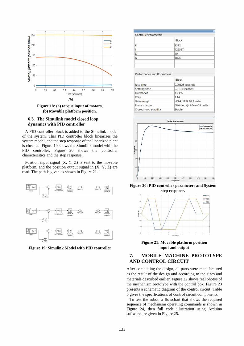
shown in Figure 17. Second, an input torque is applied to
the three motors with placing load in the opposite direction
of motion of the movable Platform, as shown in Figure 18.
Figure 17: (a) Torque input of motors,
(b) Movable platform position
(b)
(a)
(b)
(a)
(b)
(a)
123
Figure 18: (a) torque input of motors,
(b) Movable platform position.
6.3. The Simulink model closed loop
dynamics with PID controller
A PID controller block is added to the Simulink model
of the system. This PID controller block linearizes the
system model, and the step response of the linearized plant
is checked. Figure 19 shows the Simulink model with the
PID controller. Figure 20 shows the controller
characteristics and the step response.
Position input signal (X, Y, Z) is sent to the movable
platform, and the position output signal in (X, Y, Z) are
read. The path is given as shown in Figure 21.
Figure 19: Simulink Model with PID controller
Figure 20: PID controller parameters and System
step response.
Figure 21: Movable platform position
input and output
7. MOBILE MACHINE PROTOTYPE
AND CONTROL CIRCUIT
After completing the design, all parts were manufactured
as the result of the design and according to the sizes and
materials described earlier. Figure 22 shows real photos of
the mechanism prototype with the control box. Figure 23
presents a schematic diagram of the control circuit; Table
6 gives the specifications of control circuit components.
To test the robot; a flowchart that shows the required
sequence of mechanism operating commands is shown in
Figure 24, then full code illustration using Arduino
software are given in Figure 25.
(b)

124
Figure 22: (a) and (b) Real photo of mechanism prototype with the control box opened and closed
Figure23: Schematic diagram of control circuit
Figure 24: Flowchart of operating commands
(a)
(b)
Stepper
Motor
Drivers
Send to
Arduino
board
PID
Controller
Given a reference
position for mobile
table (Location X,
Y&Z)
Position
measurement
using sensor unit
Error
signal

125
Table 6: Specifications of control circuit components
Figure25: Arduino code
8. CONCLUSIONS
In this paper a 3D model was built in Solidworks for the
CNC machine, then stimulating the working area. Based
on FEA performed in Solidworks on the mobile machine
to evaluate its ability to withstand payload and to check the
deformation and the safety factor for Steel and Aluminum.
Steel material passed the test successfully, therefore, Steel
was selected because of its higher yield strength and factor
of safety, and its fewer deformation and strain.
The inverse kinematic of the derived parallel platform
position has been sequentially analyzed, and the
relationship between input tool position (X-Y-Z) and
actuated control position is briefly expressed.
Solidworks model has been transferred to Simulink
environment for dynamics simulation, relations between
motor rev/min and movable platform position was
inferred. Also, motors input torque and movable platform
position relation was concluded. A PID controller was
used to control the movable platform position against
motors input torques.
The built prototype was intentionally made out of
commercially available low-cost material to arrive at the
final design quickly. No further effort was put into a
precise evaluation of the prototype. A coarse evaluation of
the workspace, orientability, speed, load-carrying capacity
and system control is given for future better actual machine
design guidance.
The achieved design is supposed to serve as a rapid
prototyping example of a successful low cost and fully
operational Stewart platform portable CNC machine. At
the current stage the prototype is certainly not precise
enough for manufacturing purpose.
A control based MATLAB-Simulink Package will be
designed for the developed system, using PID and
Artificial intelligence techniques for future work to control
Function Specifications No. of Part No.
-Robot forward and
backward motion,
-Robot cleaning motion
Torque: 16 kg.cm
Current: 2.9A
step angel: 1.8
Motor speed: 800 r.p.m
3 Motor
Nema 23
1
Control program
development.
A microcontroller board based on the AT mega 2560, with
54 digital input/output pins (of which 15 can be used as
PWM outputs), 16 analog inputs, 4 UARTs (hardware
serial ports), a 16 MHz crystal oscillator.
1 Arduino
Mega
2560
board
2
Contact the motor to the
control circuit
TB6600 single axis 4A stepper motor driver controller 9-
40V micro-step CNC power control sockets
3 Drive
6600
3
DC power source 12 DC volt, 30 mA 1 Power
supply
4
Connect the Arduino
board to PC.
Data transfer speed is 480 Mb/sec 1 USB 2.0
cable
5
Connect the Arduino
board to power source
Input 100-240V, 50/60 Hz, 0.2A Output 5V 1 Adaptor 6

126
precisely the movable platform position, speed, and output
torque.
Credit Authorship Contribution Statement Mohamed A.O. Elamirali: conceptualization, formal
analysis, investigation, resources, original draft; Elmoushi
Elsayed: methodology, supervision; Sabreen A
Abdelwahab: methodology, validation, supervision,
formal analysis, review and editing.
Declaration of Competing Interest The authors declare that they have no known competing
financial interests or personal relationships that could have
appeared to influence the work reported in this paper.
References [1] L. Uriarte, M. Zatarain, D. Axinte, J. Yagüe-Fabra, S.
Ihlenfeldt, J. Eguia, & A. Olarra, “Machine tools for
large parts,” CIRP Ann. - Manuf. Technol., vol. 62, no.
2, pp. 731–750, 2013, doi:
10.1016/j.cirp.2013.05.009.
[2] D. Stoddart, and R. Holden, "Innovative Metrology
Integrated Robot Cell for Machining Stainless Steel in
the Manufacture of Nuclear Reaction Chambers",
SAE AeroTech Congress, Toulouse, 2011.
[3] J. Tlusty, J. Ziegert, and S. Ridgeway, "Fundamental
comparison of the use of serial and parallel kinematics
for machine tools", Annals of the CIRP, vol. 48, no.1,
pp. 351-356, 1999
https://www.sciencedirect.com/science/article/abs/pii
/S0007850607632004.
[4] M. Weck and D. Staimer, “Parallel kinematic machine
tools - Current state and future potentials,” CIRP Ann.
- Manuf. Technol., vol. 51, no. 2, pp. 671–683, Jan.
2002, doi: 10.1016/S0007-8506(07)61706-5
[5] “maxresdefault.jpg (1280×720).”
https://i.ytimg.com/vi/QrAdITL9PpI/maxresdefault.j
pg (accessed Jan. 5, 2020).
[6] C. Llopis-Albert, F. Rubio, S. Zeng, and H. Liao,
“Applied mathematics for engineering problems in
biomechanics and robotics,” Math. Probl. Eng., vol.
2019, 2019, doi: 10.1155/2019/2578916.
[7] N. Hennes, “Machine tools for future oriented
production,” Laser Metrol. Mach. Perform. VI, vol.
44, no. Lcc, pp. 287–314, 2003.
[8] N. Hennes, "Ecospeed, an innovative machinery
concept for high performance 5-axis machining of
large structural components in aircraft engineering",
Proc.of the 3rd Chemnitz Parallel Kinematic Seminar,
Chemnitz, Germany, pp.763-774, 2002.
[9] Q. Li, X. Chai, and Q. Chen, “Review on 2R1T 3-DOF
parallel mechanisms,” Kexue Tongbao/Chinese
Science Bulletin. Vol. 72, no. 14, pp.1507-
1519, 2017, doi: 10.1360/N972015-01228.
[10] C. Hu, B. Yao, Q. Wang, Z. Chen, and C. Li,
“Experimental investigation on high-performance
coordinated motion control of high-speed biaxial
systems for contouring tasks,” Int. J. Mach. Tools
Manuf., vol. 51, no. 9, pp. 677-686, 2011, doi:
10.1016/j.ijmachtools.2011.06.001.
[11] J. Zhang, Y. Q. Zhao, and H. W. Luo, “Hybrid-
model-based stiffness analysis of a three-revolute-
prismatic-spherical parallel kinematic machine,”
Proc. Inst. Mech. Eng. Part B J. Eng. Manuf., vol. 231,
no. 14, pp. 2561–2576, 2017, doi:
10.1177/0954405416634257.
[12] R. Neugebauer, M. Wabner, H. Rentzsch, and S.
Ihlenfeldt, “Structure principles of energy efficient
machine tools,” CIRP J. Manuf. Sci. Technol., vol. 4,
no. 2, pp. 136–147, Jan. 2011, doi:
10.1016/j.cirpj.2011.06.017
[13] M. Schwaar, T. Schwaar, S. Ihlenfeldt, and H.
Rentzsch " Mobile 5-axes machining centres.
In sustainable production for resource efficiency and
ecomobility", Proceedings of the 1st International
Chemnitz Manufacturing Colloquium (ICMC 2010).
Verlag Wissenschaftliche Scripten, Chemnitz (pp.
169-184).
[14] J. Zulaika, and F.J. Campa, " New concepts for
structural components, In: López de Lacalle L.,
Lamikiz A. (eds), Machine Tools for High
Performance Machining", London, Springer Verlag,
pp. 47- 73, 2010, https://doi.org/10.1007/978-1-
84800-380-4_2.
[15] D. A. Axinte, S. Abdul Shukor, and A. T. Bozdana,
“An analysis of the functional capability of an in-
house developed miniature 4-axis machine tool,” Int.
J. Mach. Tools Manuf.,
Vol. 50, no. 2, pp. 191-203, 2010, doi:
10.1016/j.ijmachtools.2009.10.005.
[16] H. N. Hansen, T. G. Eriksson, M. Arentoft, and N. A.
Paldan “Design rules for microfactory solutions,” 5th
Int. Work. Microfactories, Becanson, France, 25-27
October, 2006. http://www.lab.cnrs.fr/iwmf06/
[17] J. L. Liow, “Mechanical micromachining: a
sustainable micro-device manufacturing approach?,”
J. Clean. Prod., vol. 17, no. 7, pp. 662–667, May 2009,
doi: 10.1016/j.jclepro.2008.11.012.
[18] S. Mussa, and G. Zettl, 2011, "Steigerung der
Energieeffizienz in der Produktion: Energieeffiziente
Produktionsmaschinen. 4. Fachtagung -
Energieeffiziente Fabrik in der Automobilproduktion,
8-9 Feb., Munich, Germany.
[19] R. Neugebauer, A. Bucht, A. Illgen, and V. Wittstock,
“Piezobasierte aktor-sensorEinheit zur Uniaxialen
Schwingungskompensation,” ZWF Zeitschrift fuer
Wirtschaftlichen Fabrikbetr., vol. 102, no. 7–8, pp.
451–455, May 2007, doi: 10.3139/104.101173.
[20] H. A. El Maraghy, “Flexible and reconfigurable
manufacturing systems paradigms,” Flex. Serv.
Manuf. J., vol. 17, no. 4 SPECIAL ISSUE, pp. 261–
276, 2006, doi: 10.1007/s10696-006-9028-7.
[21] Y. Koren et al., “Reconfigurable manufacturing
systems,” CIRP Ann. - Manuf. Technol.,

127
Vol. 48, , no. 2, 1999, pp. 527-540, 1999, doi:
10.1016/S0007-8506(07)63232-6.
[22] M. Kannan and J. Saha, “A feature-based generic
setup planning for configuration synthesis of
reconfigurable machine tools,” Int. J. Adv. Manuf.
Technol., vol. 43, no. 9–10, pp. 994–1009, 2009, doi:
10.1007/s00170-008-1779-8.
[23] T. Moriwaki, “Multi-functional machine tool,” CIRP
Ann. - Manuf. Technol., Vol. 57, no. 2, pp. 736-749,
2008, doi: 10.1016/j.cirp.2008.09.004.
[24] W. Liping, X. Huayang, G. Liwen, and Z. Yu, “A
novel 3-PUU parallel mechanism and its kinematic
issues,” Robot. Comput. Integr. Manuf., Vol. 42, pp.
86-102 2016, doi: 10.1016/j.rcim.2016.05.003.
[25] L. Wang, H. Xu, and L. Guan, “Optimal design of a
3-PUU parallel mechanism with 2R1T DOFs,” Mech.
Mach. Theory, Vol. 114, pp. 190-203, 2017, doi:
10.1016/j.mechmachtheory.2017.03.008.
[26] W. Liping, X. Huayang, and G. Liwen, “Kinematics
and inverse dynamics analysis for a novel 3-PUU
parallel mechanism,” Robotica, vol. 35, no. 10, pp.
2018–2035, 2017, doi: 10.1017/S0263574716000692.
[27] Y. Li and Q. Xu, “Stiffness analysis for a 3-PUU
parallel kinematic machine,” Mech. Mach. Theory,
vol. 43, no. 2, pp. 186–200, 2008, doi:
10.1016/j.mechmachtheory.2007.02.002.
[28] “Designers SOLIDWORKS” ,
https://www.solidworks.com/solution/job-
functions/designers (accessed Jan. 21, 2020)
[29] R. Sam, K. Arrifin, and N. Buniyamin, “Simulation
of pick and place robotics system using solidworks
softmotion,” Proc. 2012 Int. Conf. Syst. Eng. Technol.
ICSET 2012, 11-12 Sept. 2012, Bandung, Indonesia,
doi: 10.1109/ICSEngT.2012.6339325.
[30] T. M. Altalmas, S. Ahmad, A. Aula, R. Akmeliawati,
and S. N. Sidek, “Mechanical design and simulation
of two-wheeled wheelchair using solidworks,” IOP
Conf. Ser. Mater. Sci. Eng., vol. 53, no. 1, 5th
International Conference on Mechatronics (ICOM'13)
2–4 July 2013, Kuala Lumpur, Malaysia 2013, doi:
10.1088/1757-899X/53/1/012042.
[31] “AISI 1035 Carbon Steel (UNS G10350).”
https://www.azom.com/article.aspx?ArticleID=6540
(accessed Feb. 11, 2020).
[32] “Wrought aluminum alloy 1060 [SubsTech].”
https://www.substech.com/dokuwiki/doku.php?id=w
rought_aluminum_alloy_1060 (accessed Feb. 11,
2020).
[33] “Simulink model design”,
https://www.mathworks.com/search.html?c%5B%5D
=entire_site&q=Simulink model design&page=1
(accessed Feb. 23, 2020).