design and simulation of fuzzy controller based (ipm...
TRANSCRIPT
UKACC International Conference on Control 2012 Cardiff, UK, 3-5 September 2012
Design and simulation of fuzzy controller based (IPM) converter fed DC Motors
Abdallah A. Ahmed, Yuanqing Xia and Bo Liu
Ahstract-This paper proposes a DSPF2812 based 32-
bit micro-controller is used to to generate PWM waveform
required to switch IPM_DRIVE, by using fuzzy logic con
troller to control dc motor fed by ACIDC (IPM) converter.
The fuzzy controller is designed in such a way that it can
be implemented in a micro-controller or DSP processor
based embedded system. The system designed consists of an
inner ON/OFF current controller and an outer fuzzy speed
controller. The fuzzy speed controller is used to change the
duty cycle of the(IPM) converter and thereby, the voltage
fed to the DC motor regulates its speed. The performance
in respect of load variation and speed change has been
reported. Simulations results are presented to demonstrate
the proposed performance and then, compared with the
reported results and found that the performance of fuzzy
based IPM_DRIVE drive for DC motors is improved.
Index Terms-Fuzzy controller, DC motors, IPM_DRIVE
converter, speed control.
I. INTRODUCTION
Since the first successful application of the fuzzy
concept into the control of a dynamic plant several
decades ago, there has been a considerable world wide
interest in fuzzy controller. It has been known that it
is possible to control many complex systems effectively
by skilled operators who have no knowledge of their
underlying dynamics, while it is difficult to achieve the
same with conventional controllers [1][2]. They are used
in several applications ranging from the control of power
converters to speed control of motors [3]. It's suitable for
applications such as the speed control of a dc motor which
has nonlinearities. It is this fact which has ultimately
made the fuzzy controller is more powerful to handle
those un-modeled uncertainties. Meanwhile, the motion
control applications can be found in ahnost every sector
of industry, from factory automation and robotics to high
tech computer hard disk drives. They are used to regulate
mechanical motions in terms of position, velocity, accel
eration and/or to coordinate the motions of multiple axes
or machine parts. Furthermore, DC motors drives have
been widely used in such applications where the accurate
speed tracking is required, and in spite of the fact that
AC motors are rugged, cheaper and lighter, DC motors
are still a very popular choice in particular applications.
It is known as a typical plant in the teaching on the
control theory and research, and many methods have been
developed for DC motors, for example, see [4], [5]-[10].
In conventional control strategies were used and it com
prises of fixed arrangement with fixed parameter design.
Hence the tuning and optimization of these controllers is a
challenging and difficult task, particularly, under varying
load conditions, parameter changes, abnormal modes of
operation.
[11] has demonstrated and reported the separately ex
cited dc motor fed by a chopper (DC to DC converter)
and controlled by a fuzzy logic controller. It has been
reported that the fuzzy logic controller controls the duty
cycle of the chopper, there by the voltage fed to the
motor for regulating the speed. The experimental setup
has improved the performance over PI controller. It is
seen that the separately excited dc drive have low starting
torque which limits its applications.
H.A.Yousef and H.M.Khalil [12] have demonstrated the
dc series motor drive fed by a single phase controlled
rectifier (AC to DC converter) and controlled by fuzzy
logic. It has been concluded that the fuzzy logic controller
provides better control over the classical PI controller
which has improved the performance. It is also reported
Abdallah Ahmed and Yuanqing Xia are with the Depart- that the settling time and maximum overshoot can bement of Automatic Control, Beijing Institute of Technology, Bei-jing 100081, China. E-mail: [email protected]. reduced. Due to the inherent limitations, AC to DC xia yuanqing@bit. edu. cn; Bo Liu is with the Systems En- converter fed drive introduces unwanted harmonic ripplesgineering Department, King Fahd University of Petroleum and Minerals, 31261 Dhaham, Saudi Arabia. E-mail: bo .liu. [email protected] in the output.
978-1-4673-1560-9/12/$31.00 ©2012 IEEE 217

[13] has reported the dc series motor drive fed by a
single phase full-bridge converter (DC to DC converter)
controlled by fuzzy logic. It has been reported that the
motor perfonnance was simulated for different controllers
like simplify fuzzy logic model (SFL), PI type fuzzy
controller (FPI) and classical PI controller. The simulation
result shows that the SFI provides superior performance
over other controllers. It is found from the analysis that
only the speed error has been taken as fuzzy input. There
are some important achievements in fuzzy controller for
closed loop control of DC drive (see, for example [14]
[20D·
The proposed system deals development of a speed
for a dc motor fed by AC/DC (lPM) converter, utilizes
the fuzzy logic controller and IPM_DRIVE (IPM power
modules). The fuzzy logic based speed command is
followed even under load torque disturbances.
The paper is structured as follows. Section II describes
the mathematical model fonnulation of the proposed DC
motors, while Section III presents the design of Fuzzy
Logic Control . Section IV, gives a simulation results and
discussion. Conclusion is given in Section V.
II. M ATHEM ATIC AL MODEL OF DC MOTORS
The goal in the development of the mathematical
model is to relate the voltage applied to the armature
to the velocity or position of the motor. Two balance
equations can be developed by considering the electrical
and mechanical characteristics of the system. Because of
the complexity of dynamic-system problems, idealizing
assumptions will be made. These assumptions are:
Assumption 2.1: The brushes are narrow, and commu
tation is linear.
Assumption 2.2: The annature is assumed to have no
effect on the total direct-axis flux because the annature
wave is perpendicular to the field axis.
Assumption 2.3: The effects of the magnetic saturation
will be neglected [21].
The electric circuit of the armature and the free body
diagram of the rotor are shown in Fig.l, where
Vi - Motor terminal voltage
Ra - Armature resistance
La- Armature inductance
J - Moment of inertia
w -Angular speed
B-Angular displacement
KT- Torque constant and
Kb- Back emf constant.
Torqlle
DampmgB
Inertia I LoadJ
Lood
Fig. 1: DC Motor Equivalent Circuit.
By choosing ia, w and B as the state variables and Vi
as input. The output is chosen to be w, and define the
system matrices Ae, Be and Ce as follows
(1)
(2)
we have the following state space description of DC
motors dynamic { Xt Yt
(3)
where state variables are
(4)
Sampling this system with step time Ts yields
(5)
where
(6)
III. Fuzzy LOGIC CONTROL (FLC)
B-Friction coefficient
'It - Load torque
Fig.2 shows the block diagram of the complete pro
posed system. The proposed system consists of DC motor, 218

IPM_DRIVE (IPM power modules) for driving the dc
motor. A tacho generator( optical encoder) is used to
measure the speed and which used for speed feedback.
A DSPF2812 based 32-bit microcontroller is used to to
generate PWM waveform required to switch Intelligent
Power Module (IPM), during the experimental setup.
Firstly, Matlab/sirnlink model of the DC motor and the
IPM_Drive power converter is developed and simulated,
and then, fuzzy logic controller is designed by using fuzzy
toolbox, finally, the closed loop operation is simulated.
Fig. 2: Black diagram of proposed system.
Intelligent Power Module: Intelligent Power Module
(IPM) is advanced hybrid power devices that combine
high speed, low loss !GBTs with optimized gate drive
and protection circuitry. System reliability is further en
hanced by the IPM's integrated over temperature and
under voltage lock out protection. Compact, automatically
assembled Intelligent Power Modules are designed to
reduce system size, cost, and time. In this paper, we
use AC/DC converter based on Intelligent Power Module
(IPM module, IRAMlOUP60B-2) to driver DC motor,
equivalent circuit of the IPM is shown in Fig.3.
The function of a fuzzy controller is to convert linguis
tic control rules based on expert knowledge into control
strategy [23]. The effective and efficient control using
fuzzy logic has emerged as a tool to deal with uncertain,
imprecise or qualitative decision making problems [24]
[30]. The FLC consists of mainly four stages, namely
Fuzzification, Rule-base, Inference engine and Defuzzifi
cation. The Takagi- Sugeno type controller is performed
for present control for DC motor because it has singleton
membership in the output variable. Moreover, it can be
easily implemented and number of calculations can be 219
AC 220 V
IPM_DRIVER Board
1-- - - - - - - - 'PM M�d�l; ----------
PWM1·4
Fig. 3: Equivalent circuit of the IPM.
reduced and works well with optimization and adaptive
techniques which makes it very attractive in control prob
lems, particularly for dynamic nonlinear systems [31].
General structure of the fuzzy controller is shown in Fig.
4, and the simulink model developed is given in Fig.5.
Fig. 4: General structure of the fuzzy controller .
a..ngein DUlyCyc1e
Fig. 5: Sirnulink scheme of the fuzzy controller.
A. Fuzzijication In this work, the motor variables considered are speed
w and current ia. The speed w is the control object
of FLC. Let Wr denote the reference speed, then the
definitions for error ek and change in error 6.ek are given
in (7) and (8).
(7)
(8)

TABLE I: Rule based of the system
� NB NS 0 PS PB
NB NB NB NB NS Z
NS NB NB NS Z PS
0 NB NS Z PS PS
PS NS Z PS PB PB
PB Z PS PB PB PB
Five linguistic variables are used for fuzzificating the
input variable ek and 6.ek as follows, Negative Big
(NB), Negative Small (NS), Zero (Z), Positive Small
(PS) and Positive Big (PB). In this work only five
membership functions are used for the input, i.e. error and
change in error. In order to reduce the number of member
ship function the width of the membership functions are
kept different. The membership function width for the
center membership functions is considered narrow and
wide towards outer.
B. defuzzification
After fuzzy reasoning we have a linguistic output
variable which needs to be translated into a crisp value.
The objective is to derive a single crisp numeric value that
best represents the inferred fuzzy values of the linguistic
output variable. The linguistic variables are converted in
to a numerical variable [32]. The defuzzified output is the
duty cycle dCk. The change in duty cycle 6.dck can be
obtained by adding the pervious duty cycle pdCk with the
duty cycle dCk which is given in Eq.(9).
,
! /
j,"" / /
coo ,
! 400 ! � /
I C""""",,y,"m
---- Fuzzy [81]
-Reference
°o��-7����,,--���--�� Time(sec)
Fig. 6: Comparisons between the proposed system and
fuzzy controller reference [34] for Wr = 1800 rpm .
Fig. 7: Current variation with respect to time .
IV. SIMUL ATION AND DISCUSSION OF THE PROPOSED
SY STEM
In this section, the effectiveness of proposed model
has been simulated using Matlab/simulink toolbox, the
designed fuzzy controller (FC) and AC/DC converter
based on Intelligent Power Module is tested. The sim-
C. Rule table and Inference Engine
(9) ulation results of the proposed fuzzy controller(FC) are
compared with fuzzy controller (FC) [34]. Fig.6 shows
the comparisons between the proposed system fuzzy con
troller and fuzzy controller reference [34] for Wr = 1800 rpm , and Fig.7 is shown Current Variation respect to
time. We can observed that, the current variation includes
The Inference Mechanism provides the mechanism
for invoking or referring to the rule base such that the
appropriate rules are fired. The control rules related to the
fuzzy output to the fuzzy inputs are derived from general
knowledge of the system behavior, also the perception
and experience. However, some of the control rules are
developed using "trial and error" method [14]. The gen
eral rule can be written as "If e( k) is X and 6.e( k) is
Y then 6.dc(k) is Z", where X, Yand Z are the fuzzy
variable for e(k), 6.e(k) and 6.dc(k) respectively . The
rule table for the designed fuzzy controller is given in the
Table I [33]. 220
some harmonics due to AC to DC converter. In order to
show the robustness of the proposed system, performance
comparisons of the proposed system with reference [12]
and reference [34] for the speed Wr = 1800 rpm is shown
in the Table II.
The simulated result of speed regulation for a step
change in load torque of 50% and 100% applied at
t = 2.5sec are shown in Fig. 8 and Fig. 9 respectively.
Fonn these figures, we can observed that the load
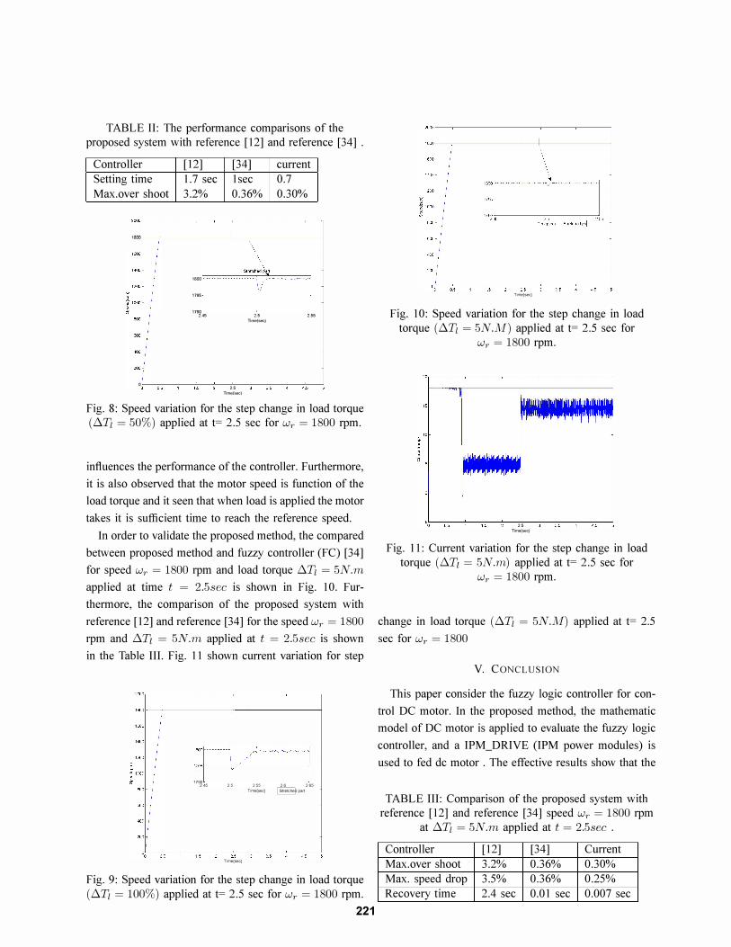
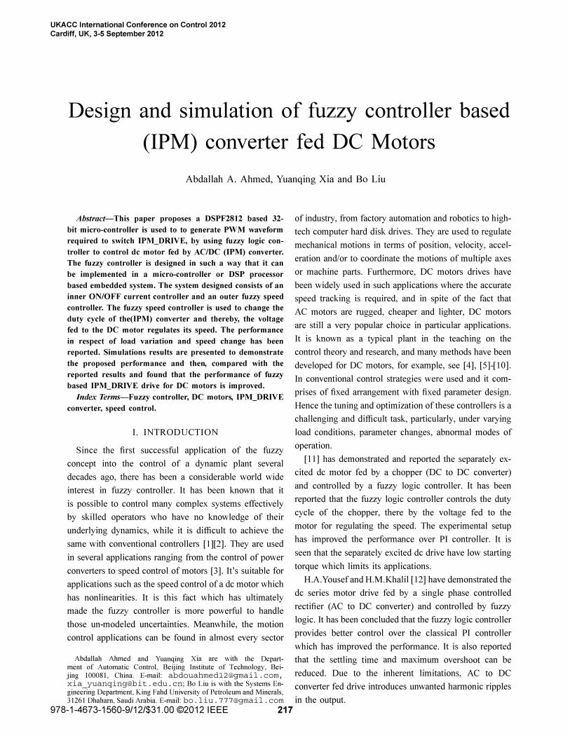
TABLE II: The performance comparisons of the
proposed system with reference [12] and reference [34] .
Controller [12]
Setting time 1.7 sec
Max.over shoot 3.2%
1000
1800
1795
1790 2.45
0
[34]
Isec
0.36%
II
'.5 lime(sec)
sui 2.5
lime(sec)
current
0.7
0.30%
'.55
Fig. 8: Speed variation for the step change in load torque
(!}.Tt = 50%) applied at t= 2.5 sec for Wr = 1800 rpm.
influences the perfonnance of the controller. Furthennore,
it is also observed that the motor speed is function of the
load torque and it seen that when load is applied the motor
takes it is sufficient time to reach the reference speed.
In order to validate the proposed method, the compared
between proposed method and fuzzy controller (FC) [34]
for speed Wr = 1800 rpm and load torque !}.Tt = 5N.mapplied at time t = 2.5sec is shown in Fig. 10. Fur
thermore, the comparison of the proposed system with
reference [12] and reference [34] for the speed Wr = 1800rpm and !}'Tl = 5N.m applied at t = 2.5sec is shown
in the Table III. Fig. 11 shown current variation for step
18oon � 1795 i v . . I 17gg 45 2.5 2_55 2_6 2_65
Tlme(sec) � part
°O������-2�'������ Tlme(sec)
Fig. 9: Speed variation for the step change in load torque
(!}.Tt = 100%) applied at t= 2.5 sec for Wr = 1800 rpm.
221
\ :::1 I 17�
4'c-
, -----c,'c-, ---�_
TIrTll'(sec) I stretChedpaft
°O���---C���'�5������ Time(sec)
Fig. 10: Speed variation for the step change in load
torque (!}.Tt = 5N.M) applied at t= 2.5 sec for
Wr = 1800 rpm.
'.5 lime(sec)
Fig. 11: Current variation for the step change in load
torque (!}'Tl = 5N.m) applied at t= 2.5 sec for
Wr = 1800 rpm.
change in load torque (!}.Tt = 5N.M) applied at t= 2.5
sec for Wr = 1800
V. CONCLUSION
This paper consider the fuzzy logic controller for con
trol DC motor. In the proposed method, the mathematic
model of DC motor is applied to evaluate the fuzzy logic
controller, and a IPM_DRIVE (IPM power modules) is
used to fed dc motor . The effective results show that the
TABLE III: Comparison of the proposed system with
reference [12] and reference [34] speed Wr = 1800 rpm
at !}.Tt = 5N.m applied at t = 2.5sec .
Controller [12] [34] Current
Max.over shoot 3.2% 0.36% 0.30%
Max. speed drop 3.5% 0.36% 0.25%
Recovery time 2.4 sec 0.01 sec 0.007 sec
perfonnance of DC motor controller has obtained better
results by using Fuzzy Logic Controller and (IPM power
modules) fed the proposed system. The designed fuzzy
logic controller also is implemented in a micro-controller.
REFERENCES
[1] J. Qiu, G. Feng, H. Gao, "Fuzzy-model-based piecewise Hoo static output feedback controller design for networked nonlinear systems," IEEE Transation on Fuzzy Systems, vol. 18, no. 5, 919-934, Oct. 2010.
[2] J. Qiu, G. Feng, H. Gao, "Asynchronous output feedback control of networked nonlinear systems with multiple packet dropouts: TS fuzzy affine model based approach," IEEE Transation on Fuzzy Systems, vol. 19, no. 6, 1014-1030, Dec. 2011.
[3] C.C. Lee, "Fuzzy logic in control system: Fuzzy Logic Controller- Part, I and II," IEEE Trans. on Systems Man and Cybernetics, Vol. 20, pp. 404 - 435,1990.
[4] Y. Kung and C. Liaw, "A fuzzy controller improving a linear model following controller for motor drives," IEEE Transactions on Fuzzy Systems, Vol. 2, no. 3 , pp.194-202, 1994.
[5] Muhammad H.Rashid, Power electronics circuits, devices and applications, 2d edition, Prentice-Hall, 1993.
[6] Philip.T.Krein, Elements of power Electronics, Oxford University Press, 1998.
[7] N.C. Jagan, Control System Second Edition, BS Publications 4-4-309, Giriraj Lane, Sultan Bazar, Hyderabad 2008.
[8] Prof. Dr.-Ing. Dr."h.c. , Control of Electrical Drives, Leonhard Technische University Braunschweig Institute for Regelungs technik published New Work 1997.
[9] S. Thompson, Control Systems Engineering and Design, Department of Mechanical and Manufacture Engineering, University of Belfast. UK Led1989.
[10] B. Chen, H. Uang and C. Tseng, "Robust tracking enhancement of robot systems including motor dynamics: a fuzzy-based dynamic game approach," IEEE Transactions on Fuzzy Systems, Vol. 6, no. 4 , pp.538-552, 1998.
[11] N.Senthil Kumar, V.Sadasivam, K.Prema, "Design and simulation of fuzzy controller for closed loop control of chopper fed embedded dc drives," IEEE international conference, POWERCON, Singapore, 2004.
[12] H. A.Yousef and H.M.Khalil "A fuzzy logic-based control of series DC motor drives," Proceedings of the IEEE International Symposium on Vol. 2, Issue 10-14, pp. 517 C 522, Ju1l995.
[13] H.L.Tan"A simplified fuzzy logic controller for DC series motor with Improve performance," IEEE International Conference on Fuzzy System, Pp. 1523-1526, 2001.
[14] T.Gupta and R.Boudreax, "Implementation of a Fuzzy Controller for DC-DC Converters Using an Inexpensive 8-Bit micro controller," IEEE Trans. on Industrial Electronics, vol. 44, no.5, pp.661-667, October 1997.
[15] G.Uma and C.Cheliamuthu, "Design and implementation of fuzzy logic control speed control system for a converter fed DC drive using 8097 micro controller," ISIE, Mexico 2000.
[16] Soliman. H. F, Mansour. M. M, Kandil. S. A, and Sharaf. A. M, "A robust tunable fuzzy logic control scheme for speed regulation of DC series motor drives," Electrical and Computer Engineering, Canadian Conference, Vol. 1, Issue 5-8, pp. 296 C 299, Sep 1995. Y.F.
222
[17] Li and C.C. Lau, "Development of fuzzy algorithms for servo system," IEEE Control System Magazine, April, 1989, pp 65-11.
[18] Hung and Ching Lu, "Design and implemetation of a digitalized fuzzy controller for dc sero drives", IEEE International Conference on Intelligent Processing systems ,China October 1997.
[19] Y. Tipsuwan and M. Y. Chow, "Fuzzy logic microcontroller implementation for DC motor speed control," in IEEE IECON'99, San Jose, CA, 1999.
[20] Adel E. EI-kholy and A. M. Dabroom, "Adaptive Fuzzy Logic Controllers for DC Drives: A Survey of the State of the art," Journal of Electrical Systems, pp. 116-145, 2006.
[21] A.E. Fitzgerald and Charles kingsley , JR. Alexander KUSKO "Electric machinery" Third Edition United State of America. 1971.
[22] Y. F. Li, and C. C. Lau, " Development of fuzzy algorithms for servo systems," IEEE Control Systems Mag., vol.9, nO,3, pp.65-72, Apr. 1989.
[23] B. S. Zhang, and J .M. Edmunds, "On fuzzy logic controllers," IEE International Conference on Control, pp.961-965, Edinburg, U. K., 1991.
[24] H. F. Soliman, M. M. Mansour,S. A. Kandil, and A. M. Sharaf, "A robust tunable fuzzy logic control scheme for speed regulation of DC series motor drives," Electrical and Computer Engineering, Canadian Conference, Vol. 1, Issue 5-8, pp. 296-299, Sep 1995.
[25] G. Acciani, G. Fornarelli, and A. Giaquinto, "A fuzzy method for global quality index evaluation of solder joints in surface mount technology," IEEE Transation on Industrial Informtics, vol. 7, no. 1, pp.115-124, Feb. 2011.
[26] K. Rajani, Mudi, and R. Pal Nikhil, Member, "A Robust SelfTuning Scheme for PI- and PD-Type Fuzzy Controllers," IEEE Transactions On Fuzzy Systems, vol. 7, no. I, pp. 2-16, Feb. 1999.
[27] H. L. Tan, N. A. Rahim, and W. P.Hew, "A dynamic input membership scheme for a fuzzy logic DC motor controller," IEEE International Conference on Fuzzy Systems vol. I, Issue 25-28, pp. 426-429 May 2003.
[28] Young 1m Cho, "Development of a new neuro-fuzzy hybrid system," Industrial Electronics Society, IECON, 30th Annual Conference of IEEE vol. 3, pp. 3184-3189, 2004.
[29] Ping-Zong Lin, Chun-Fei Hsu and Tsu-Tian Lee, "Type -2 Fuzzy Logic Controller design for Buck DC-Dc converters, " Proceedings of the IEEE International Conference on Fuzzy systems, pp. 365- 370, 2005.
[30] Jabri Majed, Chouiref Houda, Jerbi Houssem, Benhadj Braiek and Naceur, "Fuzzy logic parameter estimation of an electrical system," Systems, Signals and Devices, IEEE SSD, 5th International Multi-Conference, pp. 1-6, 2008.
[31] L. A. Zadeh, "Fuzzy sets," Information and Control, Vol. 8, pp. 338-352, 1965.
[32] L. A. Zadeh, "Fuzzy algorithms," Info. and Ctl., Vol. 12, pp. 94-102, 1968.
[33] N. Senthil Kumar, V. Sadasivam and M. Muruganandam, "A Low-cost Four-quadrant Chopper-fed Embedded DC Drive Using Fuzzy Controller," Inter National Journal of Electric Power Components and Systems, Vol. 35, Issue 8, pp. 907-920, August 2007.
[34] M. Muruganandam and M. Madheswaran, "Modeling and Simulation of Modified Fuzzy Logic Controller for Various types of DC motor Drives," IEEE International Conference on Control,Automaion, Communication and Energy conservation, June 2009.