design and simulation of an electromagnetic … · design and simulation of an electromagnetic...
TRANSCRIPT

Design and Simulation of an Electromagnetic Launcher for Ordnance
Applications Tijin Dayi1, Abhilash T Vijayan2
1,2Department of Electrical and Electronics Engineering, Rajiv Gandhi Institute of Technology, Kottayam, Kerala, India
[email protected], [email protected]
Abstract— This paper presents a model of electromagnetic coil gun launcher with simulation studies and experimental model validating the proposed strategy. Military research organisations are recently developing electromagnetic rail gun launcher for long range weapons that launch projectile electrically instead of chemical propellants at a speed exceeding Mach 7. Even though Rail gun launchers are used for long range weapons, it suffers from barrel wear down after a dozen of shell firing and weapon heat generated degrading the performance. It requires non-flammable liquid gas like nitrogen for reducing the heat generated at the rail barrel. Instead of rail guns, coil guns are more safe and accurate for high velocity military weapons. Coil gun projectile have no direct contact with the high voltage coil and the projectile is passing through the barrel axis avoiding friction causing wear down. No heat is generated between projectile and stator coils
Keyword - Electromagnetic Launcher, muzzle velocity, Lorentz force
I. INTRODUCTION
Electromagnetic Launching system is used in defence mainly for launching high-velocity missiles [1]. US Navy recently developed a 33MJ prototype which can attain a speed of MACH 7 (1 Mach= 340.3 m\s), generally atomic Blitzer rail gun [2]. According to present status, the system is capable of reaching more than 100 nautical miles (1nm = 1.852 m\s) in several minutes. Since rail guns are simple in construction, their thermal management is highly complex, and it needs plasma discharge losses. Large installation cost, high-grade thermal insulation are some of the other requirements for the rail gun type electromagnetic launcher. Thus trying to concentrate on Electromagnetic Launcher (EML), where actuator force is given by coil (or solenoid) is considered as the research topic.
Finite Element Analysis (FEA) models provide a platform for estimation and analysis of the magnetic force associated with a coil [3]. Electromagnetic launch pads find their application even in weather forecasting [4].When a current flowing through a winding produces a magnetic field, the magnetic field will exert a force (Lorentz force) given by the right-hand rule [5]. The muzzle velocity attained by the projectile used in an electromagnetic launcher is dependent on the charging voltage of the storage device.
Since a battery is switching for a small time, the battery cannot provide a high current to flow through the coil in a short period. Capacitors can provide a very high current in a minimal time, unlike a battery. The charge across the capacitor is given to coil in three steps. First, the energy needed for acceleration is stored in the capacitor. Secondly, the energy stored in the capacitor is transmitted to the projectile in shortest possible time (high energy current peak creates a strong electromagnetic field). Third, the current pulse must be switched OFF before projectile passes half of coil length to prevent from being arrested at the centre of the magnet. The product of resistance and capacitance denotes the capacitor time constant, which characterises the charging and discharging rate. Fig.1 shows the charging-discharging voltage waveform of a capacitor.
A time equalling 5τd is required for fully charging and fully discharging of capacitor; τd is the time constant of the resistor capacitor circuit (RC circuit). Below shown is the equation relating charging and discharging of capacitor. Value of τD will be small either by selecting a low value of capacitor or resistance. Then the discharging of capacitor will be faster. The equations (1) and (2) show the relationship between charging and
discharging time constants c and D with charging voltage V and capacitor voltage cV .
ISSN (Print) : 2319-8613 ISSN (Online) : 0975-4024 Tijin Dayi et al. / International Journal of Engineering and Technology (IJET)
DOI: 10.21817/ijet/2017/v9i4/170904127 Vol 9 No 4 Aug-Sep 2017 3183
Dc
Fig.1. charging-discharging voltage waveform of a capacitor
Charging:
c
c
t
cc
t
c
cc
eR
Vi
eVV
CR
)1(
*
…………….. (1)
Discharging
D
D
t
Dc
t
c
DD
eR
Vi
eVV
CR
)(
*
…………….(2)
II. CONCEPT
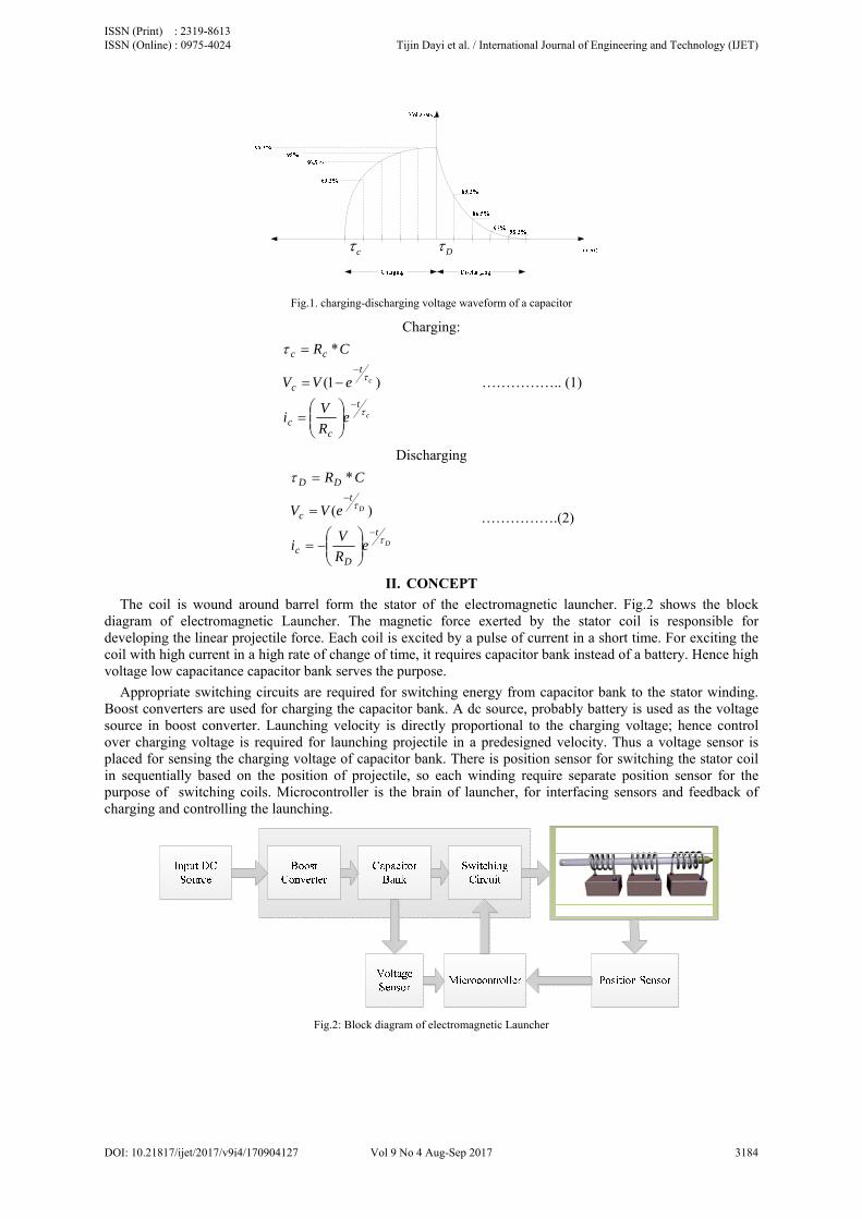
The coil is wound around barrel form the stator of the electromagnetic launcher. Fig.2 shows the block diagram of electromagnetic Launcher. The magnetic force exerted by the stator coil is responsible for developing the linear projectile force. Each coil is excited by a pulse of current in a short time. For exciting the coil with high current in a high rate of change of time, it requires capacitor bank instead of a battery. Hence high voltage low capacitance capacitor bank serves the purpose.
Appropriate switching circuits are required for switching energy from capacitor bank to the stator winding. Boost converters are used for charging the capacitor bank. A dc source, probably battery is used as the voltage source in boost converter. Launching velocity is directly proportional to the charging voltage; hence control over charging voltage is required for launching projectile in a predesigned velocity. Thus a voltage sensor is placed for sensing the charging voltage of capacitor bank. There is position sensor for switching the stator coil in sequentially based on the position of projectile, so each winding require separate position sensor for the purpose of switching coils. Microcontroller is the brain of launcher, for interfacing sensors and feedback of charging and controlling the launching.
Fig.2: Block diagram of electromagnetic Launcher
ISSN (Print) : 2319-8613 ISSN (Online) : 0975-4024 Tijin Dayi et al. / International Journal of Engineering and Technology (IJET)
DOI: 10.21817/ijet/2017/v9i4/170904127 Vol 9 No 4 Aug-Sep 2017 3184

III. MODELLING AND SIMULATION
The converter used in the circuit is an isolated boost converter. PSIM, electronic circuit simulation software for power electronic components and motor drive simulations is used for the design of the converter. COMSOL Multiphysics which provides a versatile platform for the FEA of various physics and engineering applications is used for modelling the stator coils. The application builder available with COMSOL creates specialised applications relating its physics model with a provision of user interface. This software is used for the analysis of the maximum magnetic force corresponding to a given input excitation current in a designed model created in the software
A. Converter Simulation
Fig.4 is the circuit for simulation, where the gain of the converter is around 100.Input voltage is 9 volt and output voltage will be 900 volt. The uncontrolled switch used is a MOSFET switching at a frequency of 16 kHz. Each coil is excited by separate capacitor legs from the capacitor bank as shown below.
Fig.4.Boost converter charging circuit in Psim simulation
The capacitor used in the simulation is 165uF, 900V for exciting each coil in the launcher. Fig.5 shows the input voltage and output voltage of the simulated converter in fig.4. First voltage waveform in fig.5 is the input voltage and second waveform shows the output voltage, which is around 892v.
Fig.5.input voltage and output voltage of isolated boost converter
B. Comsol Simulation
Every coils in the launcher has equal number of turns, thus it requires only analysis of one coil for understanding the magnetic field strength and magnetic force exerted by one coil. Physical specification of coil is required for modelling the stator coil, below shown is the specification of modelling of coil.
Internal radius= 8.5mm External radius= 15.43mm Coil width= 42.35mm
ISSN (Print) : 2319-8613 ISSN (Online) : 0975-4024 Tijin Dayi et al. / International Journal of Engineering and Technology (IJET)
DOI: 10.21817/ijet/2017/v9i4/170904127 Vol 9 No 4 Aug-Sep 2017 3185
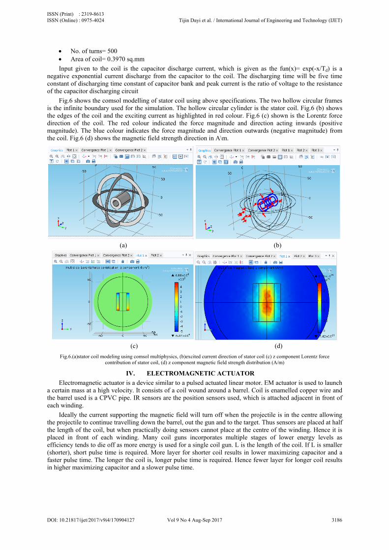
No. of turns= 500 Area of coil= 0.3970 sq.mm
Input given to the coil is the capacitor discharge current, which is given as the fun(x)= exp(-x/Td) is a negative exponential current discharge from the capacitor to the coil. The discharging time will be five time constant of discharging time constant of capacitor bank and peak current is the ratio of voltage to the resistance of the capacitor discharging circuit
Fig.6 shows the comsol modelling of stator coil using above specifications. The two hollow circular frames is the infinite boundary used for the simulation. The hollow circular cylinder is the stator coil. Fig.6 (b) shows the edges of the coil and the exciting current as highlighted in red colour. Fig.6 (c) shown is the Lorentz force direction of the coil. The red colour indicated the force magnitude and direction acting inwards (positive magnitude). The blue colour indicates the force magnitude and direction outwards (negative magnitude) from the coil. Fig.6 (d) shows the magnetic field strength direction in A\m.
(a) (b)
(c) (d)
Fig.6.(a)stator coil modeling using comsol multiphysics, (b)excited current direction of stator coil (c) z component Lorentz force contribution of stator coil, (d) z component magnetic field strength distribution (A/m)
IV. ELECTROMAGNETIC ACTUATOR
Electromagnetic actuator is a device similar to a pulsed actuated linear motor. EM actuator is used to launch a certain mass at a high velocity. It consists of a coil wound around a barrel. Coil is enamelled copper wire and the barrel used is a CPVC pipe. IR sensors are the position sensors used, which is attached adjacent in front of each winding.
Ideally the current supporting the magnetic field will turn off when the projectile is in the centre allowing the projectile to continue travelling down the barrel, out the gun and to the target. Thus sensors are placed at half the length of the coil, but when practically doing sensors cannot place at the centre of the winding. Hence it is placed in front of each winding. Many coil guns incorporates multiple stages of lower energy levels as efficiency tends to die off as more energy is used for a single coil gun. L is the length of the coil. If L is smaller (shorter), short pulse time is required. More layer for shorter coil results in lower maximizing capacitor and a faster pulse time. The longer the coil is, longer pulse time is required. Hence fewer layer for longer coil results in higher maximizing capacitor and a slower pulse time.
ISSN (Print) : 2319-8613 ISSN (Online) : 0975-4024 Tijin Dayi et al. / International Journal of Engineering and Technology (IJET)
DOI: 10.21817/ijet/2017/v9i4/170904127 Vol 9 No 4 Aug-Sep 2017 3186

V. CAPACITOR BANK
Stator winding of the electromagnetic launcher is exited from the capacitor bank as shown in fig.8. Based on the below arrangement of the capacitors, the total energy of the capacitor will be 27 Joules (E=1/2*CV2). Primarily the arrangement of the capacitor is based on the requirement of stator winding excitation current. High current density is required to generate the magnetic force. For maximizing the current density of the stator windings, capacitance value of the capacitor bank is minimized and the capacitor time constant is reduced to a lower value based on equations (2) and (3). Thus the capacitor energy can be transferred to winding in the shortest possible time with maximum possible current density.
For series connection of capacitors, ......111
321
CCC
Cequ , ......321 VVVVequ
For parallel connection of capacitors ....,321 CCCCequ
The capacitor used in the capacitor bank is 330uF, 450V (selected based on availability and ease of testing). Different arrangement of capacitor is arranged and observed the performance. Among them, parallel connection of two series capacitors are seems to be performed well. Thus the equivalent capacitance is 495uF, 900V.
VI. VOLTAGE SENSING AND CUTOFF
The projectile velocity is directly proportional to the charging voltage of the boost converter. Hence to launch a projectile of certain mass as a desired velocity, control over the charging voltage is necessary. Thus a voltage sensor is made using LM358 opamp as shown in fig.8.
Voltage divider in the above circuit uses a 20kΩ pot; the voltage at negative terminal of the opamp is also controlled by a 20kΩ pot. By controlling any of the pot in the above circuit, charging voltage of the capacitor bank can be controlled. When the voltage at the non inverting terminal (3) is greater than the inverting terminal (2), output of the opamp at terminal (1) will be 5V Vcc. An LED is placed at the output of the opamp for cut-off indication. When this cut-off signal is send to the microcontroller, the gating voltage given to the charging controlled mosfet will become low. Thus the voltage boost converter will be switched off and charging is made at cut off.
1K
10K
20K
8
4
1
3
2
Capacitor Bank
Voltage Divider
20KΩ
1MΩ
Opamp
+
-
5v Vcc
Voltage Sensor
To microcontroller
Fig.8. Circuit diagram for capacitor bank voltage sensing
VII. ELECTROMAGNETIC ACTUATOR CONVERTER
Voltage boosters are required to charge the capacitor bank. There are options such as voltage multipliers, but it requires a lot of passive elements for voltage multiplication. Thus the circuit works with a high power loss in each multiplication stage. Therefore a voltage boost converter is used as shown in fig.9. In this circuit, it has isolation between the high voltage and the low voltage; also the coupled inductor will also increase the gain of the converter.
ISSN (Print) : 2319-8613 ISSN (Online) : 0975-4024 Tijin Dayi et al. / International Journal of Engineering and Technology (IJET)
DOI: 10.21817/ijet/2017/v9i4/170904127 Vol 9 No 4 Aug-Sep 2017 3187

. .- VD +
D
r1
L1(N1)L2(N2)
r2C1
iD iC
VBAT
- VD +
D
V
IR sensor 1
IR sensor 2
IR sensor 3
Microcontroller
V Rs1 IRs2 IRs3
T1
T3
T2
S T1 T2 T3
EM LauncherSwitching
circuit
- VD +
D
Capacitor Bank
W1
W2
W3
S
Fig.9. converter used to step up the voltage for charging the capacitor bank
Gating pulse given to the mosfet at the low voltage side is at 16 kHz (0.63 duty ratio) using a 555 timer ic as shown in fig.10. The turns ratio of the coupled inductor is 1:100, with 15 turns in primary winding. 900 volt output voltage is taken to charge the capacitor bank by giving 9 volt regulated voltage as input.
Fig.10.timer circuit for mosfet gating pulse.
It is advisable to take a duty ratio of between 60 and 65 % duty ratio.
nFkCRRT
nFKCRT
usF
T
H
L
1*55*693.0*)(*693.0
1*33*693.0*)(*693.0
5.621
21
2
Designing the core of coupled inductor is based on the equation, N1A1+N2A2=AWKW. Where N1 N2 is the number of turns in primary and secondary of the coupled inductor, A1 A2 is the area of cross section of the winding wire used. Aw is the window area of the core and Kw is the window space factor.
ISSN (Print) : 2319-8613 ISSN (Online) : 0975-4024 Tijin Dayi et al. / International Journal of Engineering and Technology (IJET)
DOI: 10.21817/ijet/2017/v9i4/170904127 Vol 9 No 4 Aug-Sep 2017 3188

VIII. SWITCHING CIRCUIT
Silicon controlled rectifiers (SCRs) are used as the switching device, for controlling the stator current excitation to each winding. Since the capacitor bank is of 900 V rated capacity, SCR selected must be of greater Repetitive peak off-state voltage value. The triggering circuit for SCR is as shown in fig.11.
Fig.11. Switching circuit for switching each winding
SCR will be ON only when the gate is applied with a voltage of Vcc with respect to cathode. To switch ON SCR, transistor T1 will be ON. Similarly to switch OFF SCR, the gate pin of SCR is provided with a negative voltage or with a perfect ground voltage. Gating pulse G1 and G2 is fed from a microcontroller. Vcc fed from the microcontroller is 5 V. If gating pulse of both transistors is LOW, the SCR will be continuing conducting if it is previously ON. SCR will be OFF if it is previously OFF.
IX. CONTROLLER AND USER INTERFACE
Microcontroller is the brain of the system. 8052µc is used in the circuit. 256 bytes of internal RAM (compared to 128 in the standard 8051). A third 16 bit timer, capable of a number of new operation modes and 16 bit reloads. Additional SFRs are there to support the functionality offered by the third timer. Fig.12 shows the microcontroller circuit diagram for the interfacing of various sensor and gating pulses for the mosfet. Vcc and ground is connected at pin number 40 and 20. 8052 Microcontroller is working at a frequency of 1/4th
frequency of the crystal frequency. The crystal frequency is 16Mhz. Crystal is connected between pin 18 and 19 of the microcontroller. An LCD is provided for user interface for indicating the charging and discharging time. The 8 data pin of LCD is connected at port 0 through a resistance.
Position sensors are connected at port 2 of pin number (0 to 2). Firing switch is connected at pin p2.3. For switching one SCR, it requires gating pulse for two transistors. Hence total six gating pulse is required for the switching circuit of three stage electromagnetic launcher. The gating pulse for switching circuit is connected at port 1 at pin 0 to 5. Voltage sensor is connected at pin p1.6. Charging of electromagnetic launcher will start only after getting a high pulse at gate pin of charging control mosfet. Thus charging switch is connected at p1.7.
ISSN (Print) : 2319-8613 ISSN (Online) : 0975-4024 Tijin Dayi et al. / International Journal of Engineering and Technology (IJET)
DOI: 10.21817/ijet/2017/v9i4/170904127 Vol 9 No 4 Aug-Sep 2017 3189
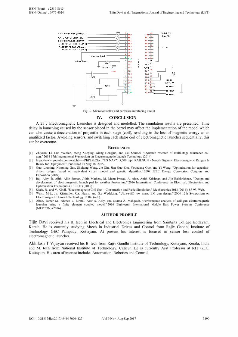
Fig.12. Microcontroller and hardware interfacing circuit
IV. CONCLUSION
A 27 J Electromagnetic Launcher is designed and modelled. The simulation results are presented. Time delay in launching caused by the sensor placed in the barrel may affect the implementation of the model which can also cause a deceleration of projectile in each stage (coil), resulting in the loss of magnetic energy as an unutilized factor. Avoiding sensors, and switching each stator coil of electromagnetic launcher sequentially, this can be overcome.
REFERENCES [1] Zhiyuan, Li, Luo Youtian, Meng Xueping, Xiang Hongjun, and Cui Shumei. "Dynamic research of multi-stage reluctance coil
gun." 2014 17th International Symposium on Electromagnetic Launch Technology (2014). [2] https://www.youtube.com/watch?v=9PItPL7EZEc, ”US NAVY 5,600 mph RAILGUN - Navy's Gigantic Electromagnetic Railgun Is
Ready for Deployment”, Published on May 18, 2015. [3] Guo, Liuming, Ningning Guo, Shuhong Wang, Jie Qiu, Jian Guo Zhu, Youguang Guo, and Yi Wang. "Optimization for capacitor-
driven coilgun based on equivalent circuit model and genetic algorithm." 2009 IEEE Energy Conversion Congress and Exposition (2009).
[4] Raj, Ajay, B. Ajith, Ajith Soman, Jithin Mathew, M. Manu Prasad, A. Ajan, Anith Krishnan, and Jijo Balakrishnan. "Design and development of electromagnetic launch pad for weather forecasting." 2016 International Conference on Electrical, Electronics, and Optimization Techniques (ICEEOT) (2016).
[5] Skala, B., and V. Kindl. "Electromagnetic Coil Gun – Construction and Basic Simulation." Mechatronics 2013 (2014): 87-93. Web. [6] Werst, M.d., J.r. Kitzmiller, C.s. Hearn, and G.a Wedeking. "Ultra-stiff, low mass, EM gun design." 2004 12th Symposium on
Electromagnetic Launch Technology, 2004. (n.d.). [7] Abdo, Tamer M., Ahmed L. Elrefai, Amr A. Adly, and Osama A. Mahgoub. "Performance analysis of coil-gun electromagnetic
launcher using a finite element coupled model." 2016 Eighteenth International Middle East Power Systems Conference (MEPCON) (2016).
AUTHOR PROFILE
Tijin Dayi received his B. tech in Electrical and Electronics Engineering from Saintgits College Kottayam, Kerala. He is currently studying Mtech in Industrial Drives and Control from Rajiv Gandhi Institute of Technology GEC Pampady, Kottayam. At present his interest is focused in sensor less control of electromagnetic launcher.
Abhilash T Vijayan received his B. tech from Rajiv Gandhi Institute of Technology, Kottayam, Kerala, India and M. tech from National Institute of Technology, Calicut. He is currently Asst Professor at RIT GEC, Kottayam. His area of interest includes Automation, Robotics and Control.
ISSN (Print) : 2319-8613 ISSN (Online) : 0975-4024 Tijin Dayi et al. / International Journal of Engineering and Technology (IJET)
DOI: 10.21817/ijet/2017/v9i4/170904127 Vol 9 No 4 Aug-Sep 2017 3190