design and simulation analysis of the truck rear impact
TRANSCRIPT

Design and Simulation Analysis of the Truck Rear Impact Energy -Absorbing Device
Min LI Department of Automotive Engineering, Dalian Vocational and Technical College, Dalian, 116037,
China email: [email protected]
Keywords: Rear-end collision, Impact energy-absorbing, Shear-bolt principle, Thin-walled beam
Abstract. To solve the defect of rear protective device of a truck which has no function of barrier and buffer energy-absorbing, a truck-mounted removable type rear protective device is designed. The impact energy is absorbed by mechanical shearing the metal bolt, is mainly used for highway truck is forced to stop, to prevent the rear of the vehicles (especially cars) drill into the bottom of the truck, which lead to great casualty. Utilizing software PRO / E and ANSYS / LS-DYNA carries on modeling and simulation. The results shows that the energy-absorbing device can be decomposed disposable collision energy, gradually reduced the collision force and gradually absorbed the energy, fundamentally avoided the car drill into the bottom of the truck to decrease collision loss and protection. According to the simulation result in full-scale collision and the energy-absorbing characteristics of thin-walled component, that put forward some improvement measures.
Introduction There is no frontal crash accident but rear-end accident in the highway traffic accident, because of the characteristics of the highway, for example, fully totally enclosed and crossed. And the highway traffic accident mostly led to serious consequences, attributed to straight road surface, high standards of road design and high speed[1]. In large trucks involved traffic accidents, the rear-end accident between a car and a truck or involved in several vehicles with higher malignancy is easy to cause fatalities. The rate and mortality of this rear-end accident are larger, about forty-six percent. And the mortality is four times as much as other accidents involved in cars[2].
For such accident, in the rear of most trucks is added a simple protection device, which mostly use channels or pipes. The protection device could have certain protective effect when the speed of the rear-end accident is low, while it will be ineffective when the speed is high. From the above, in random collisions the safe and reliable protection device should dissipate collision energy with the relatively fixed form to control the collision force and the reducing speed effective for avoiding drilling rear-end crash.
This paper makes a study of the energy-absorbing device installed in the rear of trucks. The device will play a part in warning traffic behind and protecting the life of the driver when the truck drive slowly or stop after an accident. It could moderate impact and absorb kinetic energy if two vehicles collide. Its structure is novel and different from traditional absorbing principle. The advantage of the device is to take a collision instead of multiple collisions to transfer energy, consume energy and absorb energy. So collision energy is released until exhausted by the shear and friction between components. The rear energy-absorbing device will be verified its rationality by the simulation of full width collision.
Design of the Rear Energy-Absorbing Device Functional Requirements. According to relevant provisions of GB11567.2-2001 standard, the rear energy-absorbing device will be struck by mobile barrier to test the dynamic property.
(1) Barrier function is to prevent rear-end vehicle drilling into the truck. (2) Buffering function is to buffer impact, improve crash compatibility, reduce the damage of the
3rd International Conference on Automation, Mechanical Control and Computational Engineering (AMCCE 2018)
Copyright © 2018, the Authors. Published by Atlantis Press. This is an open access article under the CC BY-NC license (http://creativecommons.org/licenses/by-nc/4.0/).
Advances in Engineering Research, volume 166
819

vehicle and protect personnel as much as possible[3]. (3) Folding and lifting function. The length and quality of the truck installed the rear
energy-absorbing device could have a certain increase. The electronic control device would control the function of folding and lifting in order to reduce the influence on the length of the truck.
Structure and Principle. The rear energy-absorbing device consists of bumper connected component, electronic control unit, mechanical control unit and the rear energy-absorbing component. Figure 1 is the installation position of the rear energy-absorbing device. Figure 2 is the structure of the rear energy-absorbing device. The rear energy-absorbing component is the main part. Four quadrate thin-walled beams and many bolts of the device form several collision shear surfaces. Both ends of the device respectively are propped up by rear guard apron and bumper connected component. Collision force pushes two thin-walled beams and produces axial relative motion for shearing bolts many times. If the axial force still greater than the shear force of bolts, the square thin-walled beams can be compressed further. By the both affection, the collision kinetic energy can be decayed gradually. The design of the rear energy-absorbing device uses the principle that shearing bolts need to consume energy. Because bolts dispersedly layout in thin-walled beams, it is good for releasing energy and reducing rebound potential energy and could avoid secondary collisions. The function of bumper connected component is to connect the truck with the energy-absorbing device by bolts. The function of electronic and mechanical control unit is to control the device being lifted up and down.
Fig.1. Installation position of the rear energy-absorbing device
Fig.2. Structure of the rear energy-absorbing device
Determination of the Structure Size. According to the working environment and characteristics of the device, combined with the knowledge of Rational Mechanics and Materials Mechanics, the structure size of the rear energy-absorbing device is estimated. The initial estimates is simple when the rear-end collision between a car and a truck in a highway. The basic parameters of the rear-end collision: The car weight is 1870kg, dimensions (length×width×height) are 4820×1807×1450mm. The truck quality is 14390kg, dimensions (length×width×height) are8490×2470×2830mm. The truck is stationary state when the accident happened. The car speed is 120km / h. Generally vehicle collision time is among 0.1 ~ 0.2 s, here take 0.1 s.
By means of calculation on the kinetic energy conservation law, the diameter of the bolt is not less than 17.3mm, according to the standard desirable bolt diameter is 20mm. The allowable maximum pitch of bolts under Code for design of steel structures standard is 240mm. The allowable minimum spacing is 60mm.The minimum edge distance of bolt is 30mm, and the maximum is 40mm. The results indicated that the total length of the energy-absorbing composite beams is 2.1m above. In order to meet the device can be folded and the truck limited the height, so the total length of the device can not be greater than the truck(2.8m). Finally the total length of the device is 2.3m.
Advances in Engineering Research, volume 166
820
In addition, according to the provisions of the safety standards and the actual situation of the suction device, the width of the device is greater than 60% of the truck width and less than the entire truck width. The calculations range value is 1.5m to 2.4m. Here is 2m.
The rear energy-absorbing device was installed in the back of the truck and can lift, so we do not consider the problem of traffic ability and select the ground clearance of the car from the maximum protective effect. For better protection , the road clearance of the device’s lower state is defined 300 mm.
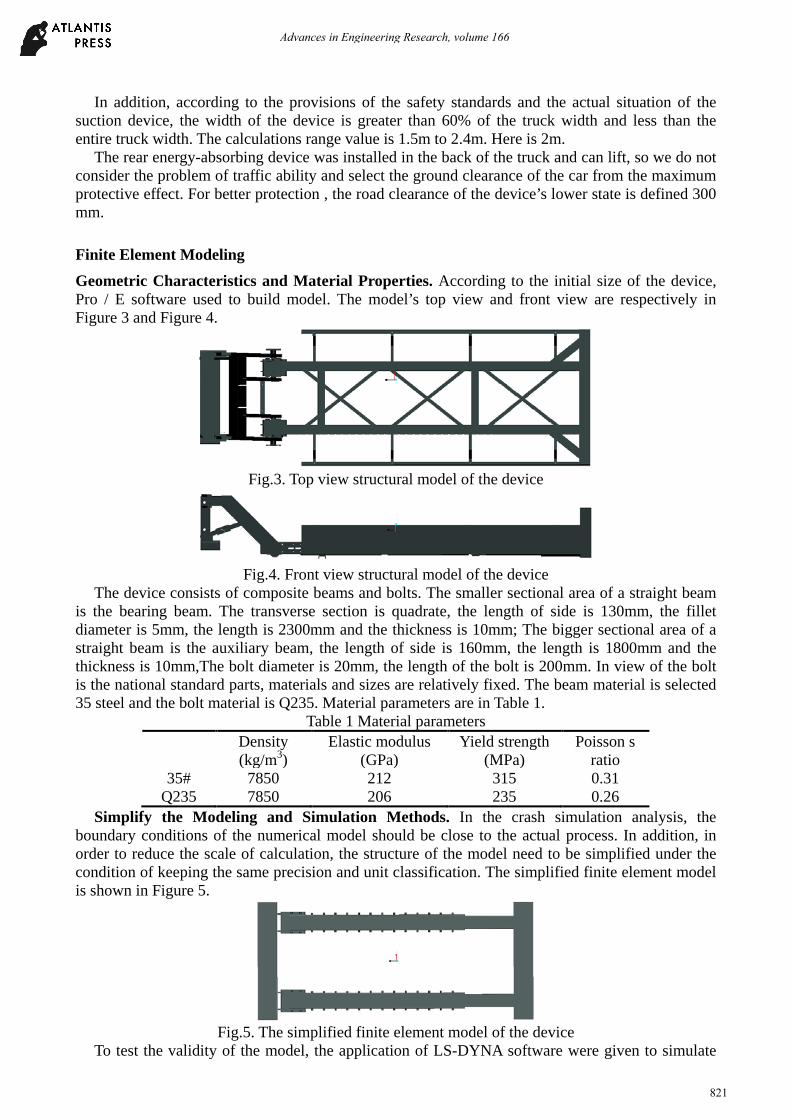
Finite Element Modeling Geometric Characteristics and Material Properties. According to the initial size of the device, Pro / E software used to build model. The model’s top view and front view are respectively in Figure 3 and Figure 4.
Fig.3. Top view structural model of the device
Fig.4. Front view structural model of the device
The device consists of composite beams and bolts. The smaller sectional area of a straight beam is the bearing beam. The transverse section is quadrate, the length of side is 130mm, the fillet diameter is 5mm, the length is 2300mm and the thickness is 10mm; The bigger sectional area of a straight beam is the auxiliary beam, the length of side is 160mm, the length is 1800mm and the thickness is 10mm,The bolt diameter is 20mm, the length of the bolt is 200mm. In view of the bolt is the national standard parts, materials and sizes are relatively fixed. The beam material is selected 35 steel and the bolt material is Q235. Material parameters are in Table 1.
Table 1 Material parameters Density
(kg/m3) Elastic modulus
(GPa) Yield strength
(MPa) Poisson s
ratio 35# 7850 212 315 0.31
Q235 7850 206 235 0.26 Simplify the Modeling and Simulation Methods. In the crash simulation analysis, the
boundary conditions of the numerical model should be close to the actual process. In addition, in order to reduce the scale of calculation, the structure of the model need to be simplified under the condition of keeping the same precision and unit classification. The simplified finite element model is shown in Figure 5.
Fig.5. The simplified finite element model of the device
To test the validity of the model, the application of LS-DYNA software were given to simulate
Advances in Engineering Research, volume 166
821
the model[4]. The entire device can be described as a large displacement, a large rotating and a big strain of the four nodes thin shell unit. The unit algorithm uses the Belytschko-Wong. Under the condition of ensuring the correct expression deformation, the control of the grid density should be possible to select the bigger unit size. Reference that thin-walled beam folded radius is R=0.72a1/3t2/3, a is the cross-section width, its value is the cross-section length or the width if the thin-walled beam is rectangular, T is the thickness. In order to accurately describe the deformation, mesh size should be less than 0.5 π R. According to the thickness and width, the numerical value of l is 26.6mm. Therefore, the unit size of thin-walled beam is set to 26 mm. When grid division is formed in this device, the total of shell elements are 39981. The type of contact is defined as the automatic single contact. The model is avoided to produce the hourglass shape through the introduction of viscous damping force. Considering the friction effect interface, in this paper determine the static friction factor is 0.08 and the dynamic friction factor is 0.06.
Build the Full Vehicle Model. This paper adopts ANSYS as the finite element software. By reading graphic files of PRO/E software three-dimension object model is established and divided into grids. The full vehicle model consists of white body, auxiliary frame, doors, suspensions, steering mechanism, engine, and radiator, etc. Engine, fuel tank and wheel hub are set to rigid bodies, and suspensions are set to stiffness consistent spring units. Finally the full vehicle model has 449882 nodes and 253164 units. Unit size changes from 5 to 25 millimeter. According to the European legal ECE R94.01 and relevant provisions[5], relative positions of the device and the rear-end car in full width collision is showed in Figure 6.
Fig.6. Relative positions relation in full width collision
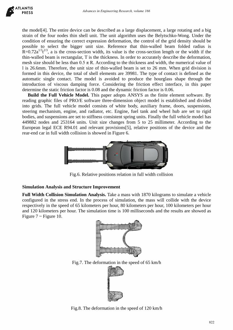
Simulation Analysis and Structure Improvement Full Width Collision Simulation Analysis. Take a mass with 1870 kilograms to simulate a vehicle configured in the stress end. In the process of simulation, the mass will collide with the device respectively in the speed of 65 kilometers per hour, 80 kilometers per hour, 100 kilometers per hour and 120 kilometers per hour. The simulation time is 100 milliseconds and the results are showed as Figure 7 ~ Figure 10.
Fig.7. The deformation in the speed of 65 km/h
Fig.8. The deformation in the speed of 120 km/h
Advances in Engineering Research, volume 166
822

Fig.9. Internal energy curves in all kinds of speed after full width collision
Fig.10. Acceleration curves in all kinds of speed after full width collision
According to the internal energy curves and acceleration curves, in the speed of 65 kilometers per hour, 80 kilometers per hour and 100 kilometers per hour, the device has a reasonable deformation and can effectively absorb collision kinetic energy from 67106 J to 95082 J. In the speed of 120 kilometers per hour, the device hasn’t absorbed all collision kinetic energy, but it also can prevent cars driving into the rear of the truck.
Peak acceleration is mostly seen between 10 and 20 milliseconds. In the time the rear-end vehicle has been impacted seriously, however the device could gradually reduce collisions acceleration in order to protect the staff of the car.
Summary (1) In ANSYS/LS-DYNA, the simulation model of the rear energy-absorbing device is established successfully and then simulations go smoothly. The simulation results verify the structure of the device is reasonable. Product design cycle can be reduced greatly by using simulation software.
(2) The energy-absorbing process has good robustness. Because the rear energy-absorbing device could absorb energy successfully by shearing bolts when the car’s impact direction and the device’s axis are consistent or have a distance bias.
(3) The structure of the device is simple and convenient for replacement. According to the full width collision simulation results, in the speed of 65 kilometers per hour, 80 kilometers per hour and 100 kilometers per hour, the device has a reasonable deformation and can effectively absorb collision kinetic energy. But in the speed of 120 kilometers per hour, the device hasn’t absorbed all collision kinetic energy.
(4) There are several weakening slots in the side of thin-walled beams to meet the requirements of energy saving, etc. So the device has a good specific energy absorption, that means unit mass can absorb more energy.
References
[1] Yang Zhao, Dajun Yue, Ying Xu, Guangzhi Zhang. The Analysis of Actuality and Improvement Actions of Underrun Guard of Truck [J]. Agricultural Equipment Vehicle Engineering, 2010 (1)
Advances in Engineering Research, volume 166
823

11-13.
[2] Xin Zhang, Shanbin Lu, Haili Liu, Junyuan Zhang. Design of a New Type of Truck Rear Underrun Protective Device [J]. Automobile technology, 2011 (6) 19-23.
[3] Zhihua Zhong, Weigang Zhang, Libo Cao, Wen He. Automotive Crash Safety Technology. Beijing, China Machine Press, 2003.
[4] Yushu Yin, Haiting Zhou, Shifu Wang, Yuejian Wang, Hongjian Li. A New Type of Energy Absorber for Vehicle Impact [J]. Automotive Engineering, 2006 (7) 656-658.
[5] Can Li. Crashworthiness Optimization Research for The Structure of Car Body. Chongqing University of Technology, 2014.
Advances in Engineering Research, volume 166
824