design and safety analysis of emergency brake system for ...1285512/fulltext01.pdf ·...
TRANSCRIPT

IN DEGREE PROJECT VEHICLE ENGINEERING,SECOND CYCLE, 30 CREDITS
, STOCKHOLM SWEDEN 2018
Design and Safety Analysis of Emergency Brake System for Autonomous Formula Car
In Reference to Functional Safety ISO 26262
MARKUS BÖLANDER
KTH ROYAL INSTITUTE OF TECHNOLOGYSCHOOL OF ENGINEERING SCIENCES
Master of Science Thesis SD221X: Degree Projectin Vehicle Engineering
Design and Safety Analysis of EmergencyBrake System for Autonomous Formula Car
Markus Bölander
Approved Examiner Supervisor
2018-06-27 Mikael Nybacka Julian KollerCommissioner Contact person
AVL Julian Koller
Abstract
The engineering competition Formula Student has introduced a Driverless Vehicle (DV)class, which requires the students to develop a car that can autonomously make its wayaround a cone track. To ensure the safety of such a vehicle, an Emergency Brake System(EBS) is required. The EBS shall ensure transition to safe state for detection of a singlefailure mode. This thesis work covers the design of the EBS for KTH Formula Student(KTH FS).
Due to the safety critical character of this system, the software part of the EBS, calledEBS Supervisor, has been analyzed in accordance with the safety standard ISO 26262 tosee if an improved safety could be achieved. The analysis has been perform according toPart 3: Concept phase of ISO 26262 with an item definition, Hazard Analysis and RiskAssessment (HARA), Functional Safety Concept (FSC) and Technical Safety Concept(TSC).
The result of the analysis showed that the EBS Supervisor requires extensive redundanciesin order to follow ISO 26262. This includes an additional CPU as well as signal checksof inputs and outputs. Due to limited resources in terms of money and time within theKTH FS team, these redundancies will not be implemented. The process of working withthe safety standard did however inspire an increased safety mindset.
Keywords: Emergency Brake System, Formula Student, Functional Safety, ISO 26262
ii

Examensarbete SD221X: Degree Project in VehicleEngineering
Design och Säkerhetsanalys av Nödbroms förAutonom Formula Bil
Markus Bölander
Godkänt Examinator Handledare
2018-06-27 Mikael Nybacka Julian KollerUppdragsgivare Kontaktperson
AVL Julian Koller
Sammanfattning
Ingenjörstävlingen Formula Student har introducerat en förarlös tävlingsklass (eng:Driverless Vehicle) som innebär att studenterna ska utveckla en bil som autonomt kan tasig runt en konbana. För att försäkra sig om säkerheten för ett sådant fordon krävs ettnödbromssystem (eng: Emergency Brake System (EBS)). EBS:en skall försäkra att enövergång till ett säkert tillstånd sker då ett singulärt fel upptäcks. Det här examensarbetetbehandlar designen av EBS:en för KTH Formula Student.
På grund av den säkerhetskritiska karaktären hos detta system har mjukvarudelen avEBS:en, kallad EBS Supervisor, blivit analyserad utifrån säkerhetsstandarden ISO 26262för att se om en förbättrad säkerhet kunde uppnås. Analysen har blivit genomfördenligt Del 3: Konceptfas av ISO 26262 med item definition, Hazard Analysis and RiskAssessment, Functional Safety Concept och Technical Safety Concept.
Resultatet av analysen visade att EBS Supervisor kräver omfattande redundanser föratt uppfylla ISO 26262. Detta inkluderar en extra CPU såväl som kontroller av in-och utsignaler. På grund av begränsade resurser i form av pengar och tid inom KTHFS, valdes dessa redundanser att inte implementeras. Processen av att arbeta medsäkerhetsstandarden har dock inspirerat ett ökat säkerhetstänk.
Nyckelord: Nödbromssystem, Formula Student, funktionell säkerhet, ISO 26262
iii

Acknowledgments
As I am finishing up the last parts of this thesis, I cannot help but to reflect uponthe five years of studies that are coming to an end. There has been a lot of hardwork in combination with cherished moments. The last two years of Master’s studiesin combination with Formula Student has been incredibly educational. Especially thislast semester where I have learned a surprisingly large amount of interdisciplinarymatters.
I would like to address my gratitude towards AVL and my supervisor Julian Koller for afun and informative time at the company. It has been a great work environment andJulian has cleared any question or doubts regarding the area of functional safety.
A large gratitude for this year’s Formula Student team is given for all the long days andnights in the garage. The different cultural and technical backgrounds have inspireddozens of interesting discussions and solutions.
Lastly, I would like to mention my friends Max Ahlberg and Fabian Källström. Theamount of laughter and humor we have had during the long hours of effort has beenpriceless. Thank you for inspiring to work even harder.
iv
Contents
Abstract ii
Sammanfattning iii
Acknowledgments iv
Acronyms viii
1 Introduction 11.1 Background . . . . . . . . . . . . . . . . . . . . . . . . . . . . . . . . . . . 11.2 Formula Student . . . . . . . . . . . . . . . . . . . . . . . . . . . . . . . . 21.3 Aim . . . . . . . . . . . . . . . . . . . . . . . . . . . . . . . . . . . . . . . 31.4 Previous research . . . . . . . . . . . . . . . . . . . . . . . . . . . . . . . . 31.5 Methodology and research questions . . . . . . . . . . . . . . . . . . . . . 41.6 Scope . . . . . . . . . . . . . . . . . . . . . . . . . . . . . . . . . . . . . . 41.7 Organization of the thesis . . . . . . . . . . . . . . . . . . . . . . . . . . . 4
2 Functional Safety 52.1 Background to functional safety . . . . . . . . . . . . . . . . . . . . . . . . 52.2 The ISO 26262 standard . . . . . . . . . . . . . . . . . . . . . . . . . . . . 6
3 Emergency Brake System 103.1 Hardware . . . . . . . . . . . . . . . . . . . . . . . . . . . . . . . . . . . . 10
3.1.1 Pneumatic brake system . . . . . . . . . . . . . . . . . . . . . . . . 103.1.2 Service brake actuator . . . . . . . . . . . . . . . . . . . . . . . . . 143.1.3 Non-programmable logic . . . . . . . . . . . . . . . . . . . . . . . . 14
3.2 Software . . . . . . . . . . . . . . . . . . . . . . . . . . . . . . . . . . . . . 153.2.1 Brake heading control . . . . . . . . . . . . . . . . . . . . . . . . . 163.2.2 Initial checkup sequence . . . . . . . . . . . . . . . . . . . . . . . . 173.2.3 Continuous monitoring . . . . . . . . . . . . . . . . . . . . . . . . . 20
3.3 Testing and functionality validation . . . . . . . . . . . . . . . . . . . . . . 23
4 Concept Phase 244.1 Item Definition . . . . . . . . . . . . . . . . . . . . . . . . . . . . . . . . . 24
4.1.1 Scope of item . . . . . . . . . . . . . . . . . . . . . . . . . . . . . . 254.1.2 Item overview on vehicle level . . . . . . . . . . . . . . . . . . . . . 254.1.3 Interaction with other items . . . . . . . . . . . . . . . . . . . . . . 264.1.4 Functional description of related elements . . . . . . . . . . . . . . 294.1.5 Main operation modes and states of the item . . . . . . . . . . . . 324.1.6 Functional Description of Item . . . . . . . . . . . . . . . . . . . . 33
v
4.1.7 Environmental Conditions . . . . . . . . . . . . . . . . . . . . . . . 374.2 Hazard Analysis and Risk Assessment (HARA) . . . . . . . . . . . . . . . 38
4.2.1 Hazard and Operability Study (HAZOP) . . . . . . . . . . . . . . 384.2.2 Hazardous Scenarios . . . . . . . . . . . . . . . . . . . . . . . . . . 394.2.3 ASIL Classification . . . . . . . . . . . . . . . . . . . . . . . . . . . 424.2.4 Safety Goals . . . . . . . . . . . . . . . . . . . . . . . . . . . . . . 44
4.3 Functional Safety Concept . . . . . . . . . . . . . . . . . . . . . . . . . . . 464.3.1 SG1: Avoid unintended take-off . . . . . . . . . . . . . . . . . . . . 464.3.2 SG2: Ensure brake functionality . . . . . . . . . . . . . . . . . . . 474.3.3 SG3: Ensure brake trigger functionality . . . . . . . . . . . . . . . 484.3.4 SG4: Ensure zero yaw motion during braking . . . . . . . . . . . . 494.3.5 SG5: Ensure steering functionality . . . . . . . . . . . . . . . . . . 504.3.6 Common requirements . . . . . . . . . . . . . . . . . . . . . . . . . 514.3.7 Summary of functional safety requirements . . . . . . . . . . . . . 52
4.4 Technical Safety Concept . . . . . . . . . . . . . . . . . . . . . . . . . . . 534.4.1 SG1: Avoid unintended take-off . . . . . . . . . . . . . . . . . . . . 534.4.2 General Requirements . . . . . . . . . . . . . . . . . . . . . . . . . 544.4.3 Considered hardware architecture . . . . . . . . . . . . . . . . . . . 544.4.4 Three level monitoring concept . . . . . . . . . . . . . . . . . . . . 55
5 Results 575.1 RQ1: How shall the EBS be design for KTH FS? . . . . . . . . . . . . . . 575.2 RQ2: What are the measures for functional safety? . . . . . . . . . . . . . 575.3 RQ3: What potential faults, hazards and risks in the EBS are relevant for
the Formula Student application? . . . . . . . . . . . . . . . . . . . . . . . 585.4 RQ4: Is the EBS fulfilling the ISO 26262 standard? . . . . . . . . . . . . . 585.5 RQ5: Can ISO 26262 be a useful standard for KTH FS to implement in
their work process? . . . . . . . . . . . . . . . . . . . . . . . . . . . . . . . 59
6 Discussion and Conclusions 606.1 Documentation . . . . . . . . . . . . . . . . . . . . . . . . . . . . . . . . . 606.2 Level of detail . . . . . . . . . . . . . . . . . . . . . . . . . . . . . . . . . . 606.3 ASIL Classification . . . . . . . . . . . . . . . . . . . . . . . . . . . . . . . 616.4 ISO 26262 for Autonomous Systems . . . . . . . . . . . . . . . . . . . . . 616.5 Quality Management . . . . . . . . . . . . . . . . . . . . . . . . . . . . . . 626.6 The EBS Supervisor as an Item . . . . . . . . . . . . . . . . . . . . . . . . 626.7 Further Work and Improvements . . . . . . . . . . . . . . . . . . . . . . . 62
References 64
Appendices 66A Formula Student Rules . . . . . . . . . . . . . . . . . . . . . . . . . . . . . 66B Fault Tolerant Time Interval . . . . . . . . . . . . . . . . . . . . . . . . . 68C Hazard and Operability Study (HAZOP) Table . . . . . . . . . . . . . . . 70D Hazardous Scenarios . . . . . . . . . . . . . . . . . . . . . . . . . . . . . . 74E Hazard and Risk Analysis . . . . . . . . . . . . . . . . . . . . . . . . . . . 77F ASIL Classification . . . . . . . . . . . . . . . . . . . . . . . . . . . . . . . 80
vi

G Technical Safety Requirements . . . . . . . . . . . . . . . . . . . . . . . . 84
vii
Acronyms
AAAM Association for theAdvancement of AutomotiveMedicine
AD Autonomous Driving
ADAS Advanced Driver AssistanceSystems
AIR Accumulator IsolationRelay
AIS Abbreviated Injury Scale
AS Autonomous System
ASIL Automotive Safety IntegrityLevel
ASMS Autonomous System MasterSwitch
AV autonomous vehicles
BHC Brake Heading Control
CPU Central Processing Unit
CV Combustion Vehicle
DC Direct Current
DTI Diagnostic Test Interval
DV Driverless Vehicle
E/E Electrical and/orelectronic
EBS Emergency BrakeSystem
EV Electric Vehicle
FMEA Failure Modes and EffectsAnalysis
FRT Fault Reaction Time
FS Formula Student
FSC Functional SafetyConcept
FSR Functional SafetyRequirement
FTA Fault Tree Analysis
FTTI Fault Tolerant TimeInterval
GLVMS Grounded Low Voltage MasterSwitch
HARA Hazard Analysis and RiskAssessment
HAZOP Hazard and OperabilityStudy
HIL Hardware in the loop
IMU Inertial MeasurementUnit
ISO International Organization forStandardization
KTH FS KTH Formula Student
LIDAR Light Detection andRanging
MIL Model in the loop
viii

MPC Model PredictiveControl
PCB Printed Circuit Board
PIL Processor in the loop
PWM Pulse Width Modulation
QM Quality Management
ROS Robot Operating System
RQ Research Question
SG Safety Goal
SLAM Simultaneous Localization andMapping
SOTIF Safety of the IntendedFunctionality
TSC Technical SafetyConcept
TSR Technical SafetyRequirement
VCU Vehicle Control Unit
ix

Chapter 1
Introduction
The following chapter aims to give an introduction to this Master’s thesis paper. Abackground regarding the addressed topics of functional safety and Formula Student isgiven and followed by a presentation of previous research in the same field. The usedmethodology and research questions stated for this work are also presented.
1.1 Background
The automobile has seen a large change and development since its conception in thelate 1800s [1]. As it has enabled inhabitants to travel longer distances with resultingimpacts on society and economy globally [2], consequences in terms of fatalities has alsofollowed. With 1.3 million people dying of road injuries in 2015 [3], road injuries is thetop 10 cause of death worldwide. This has made safety a highly prioritized issue for carmanufacturers and it is one of the major changes that the automobile has seen throughoutthe years. Advanced deformation zones have improved passive safety for modern vehiclesand active safety has been introduced to avoid accidents all together. Features like ABS,ESP, automated braking and lane keep assistance are examples of such systems thataim to assist the driver. These are referred to as Advanced Driver Assistance Systems(ADAS) and can be seen as stepping-stones in the transition towards Autonomous Driving(AD). By replacing the driver, a large amount of accidents could be avoided due to thenature of human behaviour [4]. With the "human factor" being involved in 90-95 %of all road accidents [5], replacing the driver with computers seems justified. However,these computers and algorithms are increasing in numbers and complexity, and henceensuring its reliability becomes more difficult. That is why functional safety and thesafety standard ISO 26262 becomes a crucial part of automotive development.
The trend of AD is seen in the industry as well as within academia. Large car manufac-turers are developing their own Autonomous System (AS) and many consultant firmsare a part of this development. One of these is the Austrian automobile consultantcompany AVL, with functional safety as one of their key competencies. An exampleof AD development within academia is the project KTH FS where a single seated racecar with AD features is developed. With AVL being one of KTH FS’s main partners, a
1

Chapter 1. Introduction
collaboration in terms of investigating functional safety for the KTH FS race car laid thefoundation for this thesis work.
1.2 Formula Student
Formula Student (FS) is Europe’s most established educational engineering competition[6], with the purpose of improving engineering student’s skills in design, manufacturingand financing. The challenge is to design and construct a single-seated formula style racecar as illustrated in figure 1.1.
Figure 1.1. Rendering of a typical Formula Student race car.
The competition that has previously consisted of a combustion (CV) and an electric(EV) class is for 2018 introducing a driverless class (DV). The CV and EV classes arecompeting under similar conditions while the DV class is evaluated separately. Thecompetition is divided into static and dynamic events according to table 1.1. During thedesign of the race car the students need to consider a 130 pages long rulebook [7]. Itconsists of rules in terms of how the contest shall be performed as well as requirementsregarding the design of the vehicle. One of these requirements is the presence of an EBSfor the DV. With its safety critical character, the EBS should be designed so that a singlefailure mode triggers the brakes and stops the car to a safe state. Since the safety aspectsof the vehicle is a central part of the competition judges scrutiny, a rigorous design willbe needed. This thesis will deal with the design of the EBS for KTH FS, followed by asafety analysis in reference to the safety standard ISO 26262 to justify the design.
2

1.3. Aim
Table 1.1. Maximum possible points for each event.
CV & EV DVStatic events:Business Plan Presentation 75 points 75 pointsCost and Manufacturing 100 points 100 pointsEngineering Design 150 points 325 pointsDynamic events:Skid Pad 75 points 75 pointsAcceleration 75 points 75 pointsAutocross 100 points -Endurance 325 points -Efficiency 100 points 100 pointsTrackdrive - 250 pointsOverall 1000 points 1000 points
1.3 Aim
There were two aims for this thesis; to design and develop the required EBS for theKTH FS car and to investigate its safety in regards to ISO 26262. This included athorough study of the standard in order to acquire adequate understanding of how touse it. The analysis could then be performed while following the steps described in thesafety standard.
1.4 Previous research
Since the release of ISO 26262 in 2011, plenty of articles and papers related to the topichave been published [8–13]. In [8] the concept phase of the ISO 26262 is discussed whilein [9] a brake-by-wire system is analyzed in regards to the standard. In preparation ofthe second edition of ISO 26262 that will include heavy vehicles, research has been donein order to prepare OEMs for future requirements. However, since these papers concernimplementation of a specific product the detail of information in [10, 11] is limited dueto confidentiality.
Previous research of implementing functional safety for autonomous systems is alsoscarce. The ISO 26262 standard does not currently include self driving cars and howfunctional safety should be implemented on such systems is currently an uncharted area.A suggestions with triple core redundancy is seen in [12] and some potential difficultieswhen applying ISO 26262 for autonomous vehicles (AV) are discussed in [13].
With the Formula Student Driverless competition being introduced in 2017 and withthe EBS being a new requirement for 2018, there are currently no documentation offunctional safety for such a system and context.
3

Chapter 1. Introduction
1.5 Methodology and research questions
When discussing research methodology, one must understand the difference betweenscientific and engineering methodology. While science aims to reach understanding,explanation and prediction of the universe, engineering aims to design an artifact thatsolves a practical problem [14]. This makes research in the separate areas differentand one should not force-fit engineering research into scientific conceptions of generalconclusions. In this thesis a methodology referred to as engineering design [15, 16] hasbeen used, meaning that a systematic approach to create a sufficient solution to a specificproblem has been done. The problem in this thesis is how one can or shall design andassure the safety of an EBS. Some Research Questions (RQs) that arise for this problemare presented below.
RQ1: How shall the EBS be design for KTH FS?RQ2: What are the measures for functional safety?RQ3: What potential faults, hazards and risks in the EBS are relevant for the FormulaStudent application?RQ4: Is the EBS fulfilling the ISO 26262 standard?RQ5: Can ISO 26262 be a useful standard for KTH FS to implement in their workprocess?
According to [17], one should consider if the research questions fulfill something abbreviate"FINER", standing for feasible, interesting, novel, ethical and relevant. All of the definedRQs are perhaps not fulfilling each one of these criteria but will nevertheless be used inorder to give structure to the thesis.
1.6 Scope
Due to the immensity of ISO 26262, it was decided to not include all parts of the standard.Instead, focus in this thesis work was put on Part 3 - Concept phase [18] and the technicalsafety concept from Part 4 [19]. In addition to the functional safety analysis, the actualEBS with software and hardware was developed and tested together with the FormulaStudent team at KTH.
1.7 Organization of the thesis
The report is structured in the following manner. Chapter 2 will give an introductionto functional safety and describe the origin of ISO 26262 as well as the workflow of thestandard. This is followed by a description of the EBS with its hardware and softwarein Chapter 3. With an understanding of the system, the safety analysis according toISO 26262 is performed in Chapter 4, followed by the results of the findings to thedefined research questions in Chapter 5. The report is then concluded with a chapter ofconclusions and discussions in Chapter 6.
4
Chapter 2
Functional Safety
The following chapter gives an introduction to the area of functional safety. The widerterm used in different industries is explained and followed by the use within the automotiveindustry in the form of ISO 26262.
2.1 Background to functional safety
Safety within the automotive industry has traditionally relied on robust design as wellas hydraulic and pneumatic mechanisms [20]. Mechanically fixed steering column, twocircuit hydraulic brake system, hand brake and engine braking have been used to ensurevehicle functionality. By having a robust brake system with higher brake torque than themaximum traction torque, transition to a safe state is presumably ensured. However, withincreased electrification and automation like steer-by-wire/brake-by-wire and automateddriving, software based safety mechanisms have become essential, see figure 2.1. Theoil and gas industry, nuclear plants and machinery sector all rely on functional safetyand the IEC 61508 standard by the International Electrotechnical Commission [21].This standard has been used to create ISO 26262 which is an adaption to comply withElectrical and/or electronic (E/E) systems within road vehicles [22].
To quickly grasp the concept of functional safety, one can start with the definition from[22], which describes functional safety as:
"Absence of unreasonable risk due to hazards caused bymalfunctioning behavior of E/E systems."
This includes the increased risks of systematic and random failures that could occur withincreased technological complexity, software content and mechatronic implementations.Examples of such include driver assistance, propulsion, vehicle dynamics control as wellas active safety systems. The next section will give deeper insight into how ISO 26262includes guidance to mitigation of these risks by providing appropriate requirements andprocesses.
5
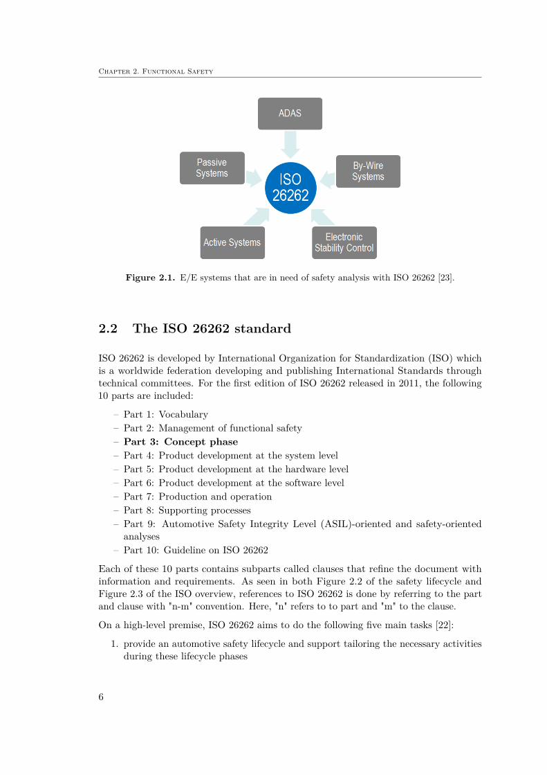
Chapter 2. Functional Safety
Figure 2.1. E/E systems that are in need of safety analysis with ISO 26262 [23].
2.2 The ISO 26262 standard
ISO 26262 is developed by International Organization for Standardization (ISO) whichis a worldwide federation developing and publishing International Standards throughtechnical committees. For the first edition of ISO 26262 released in 2011, the following10 parts are included:
– Part 1: Vocabulary– Part 2: Management of functional safety– Part 3: Concept phase– Part 4: Product development at the system level– Part 5: Product development at the hardware level– Part 6: Product development at the software level– Part 7: Production and operation– Part 8: Supporting processes– Part 9: Automotive Safety Integrity Level (ASIL)-oriented and safety-oriented
analyses– Part 10: Guideline on ISO 26262
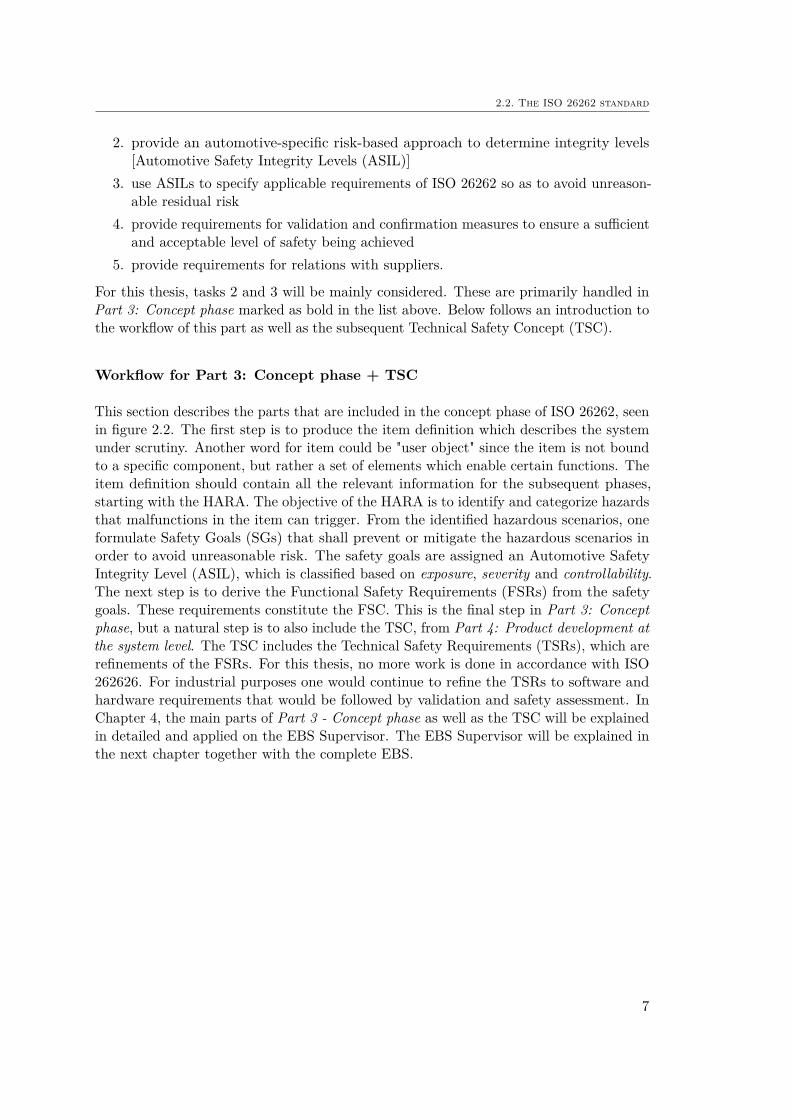
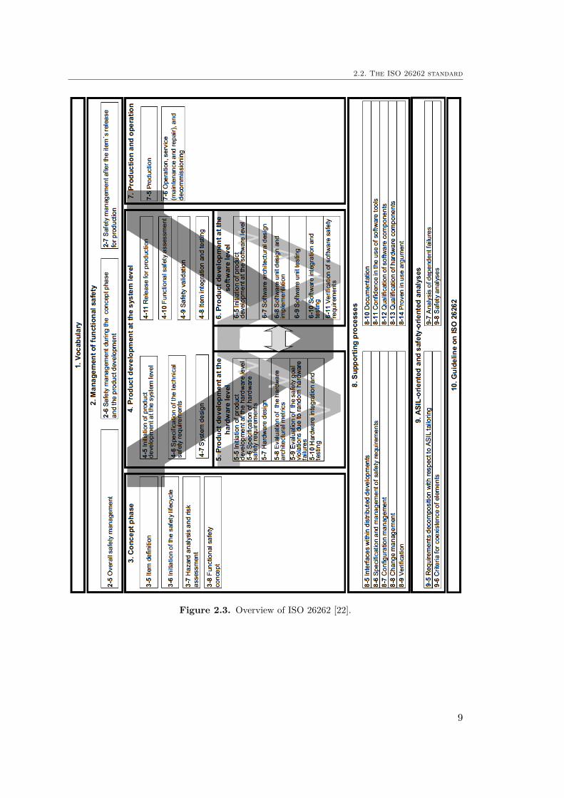
Each of these 10 parts contains subparts called clauses that refine the document withinformation and requirements. As seen in both Figure 2.2 of the safety lifecycle andFigure 2.3 of the ISO overview, references to ISO 26262 is done by referring to the partand clause with "n-m" convention. Here, "n" refers to to part and "m" to the clause.
On a high-level premise, ISO 26262 aims to do the following five main tasks [22]:
1. provide an automotive safety lifecycle and support tailoring the necessary activitiesduring these lifecycle phases
6
2.2. The ISO 26262 standard
2. provide an automotive-specific risk-based approach to determine integrity levels[Automotive Safety Integrity Levels (ASIL)]
3. use ASILs to specify applicable requirements of ISO 26262 so as to avoid unreason-able residual risk
4. provide requirements for validation and confirmation measures to ensure a sufficientand acceptable level of safety being achieved
5. provide requirements for relations with suppliers.
For this thesis, tasks 2 and 3 will be mainly considered. These are primarily handled inPart 3: Concept phase marked as bold in the list above. Below follows an introduction tothe workflow of this part as well as the subsequent Technical Safety Concept (TSC).
Workflow for Part 3: Concept phase + TSC
This section describes the parts that are included in the concept phase of ISO 26262, seenin figure 2.2. The first step is to produce the item definition which describes the systemunder scrutiny. Another word for item could be "user object" since the item is not boundto a specific component, but rather a set of elements which enable certain functions. Theitem definition should contain all the relevant information for the subsequent phases,starting with the HARA. The objective of the HARA is to identify and categorize hazardsthat malfunctions in the item can trigger. From the identified hazardous scenarios, oneformulate Safety Goals (SGs) that shall prevent or mitigate the hazardous scenarios inorder to avoid unreasonable risk. The safety goals are assigned an Automotive SafetyIntegrity Level (ASIL), which is classified based on exposure, severity and controllability.The next step is to derive the Functional Safety Requirements (FSRs) from the safetygoals. These requirements constitute the FSC. This is the final step in Part 3: Conceptphase, but a natural step is to also include the TSC, from Part 4: Product development atthe system level. The TSC includes the Technical Safety Requirements (TSRs), which arerefinements of the FSRs. For this thesis, no more work is done in accordance with ISO262626. For industrial purposes one would continue to refine the TSRs to software andhardware requirements that would be followed by validation and safety assessment. InChapter 4, the main parts of Part 3 - Concept phase as well as the TSC will be explainedin detailed and applied on the EBS Supervisor. The EBS Supervisor will be explained inthe next chapter together with the complete EBS.
7

Chapter 2. Functional Safety
Figure 2.2. Extract of the safety lifecycle according to ISO 26262-2:2011 5.2 [24].
8
2.2. The ISO 26262 standard
Figure 2.3. Overview of ISO 26262 [22].
9
Chapter 3
Emergency Brake System
This chapter gives an introduction to the preliminary design and architecture of theEBS that was made. This was used as the background for the item definition describedin section 4.1. The following sections will describe the actual implemented hardwareand generated Simulink software, while the item definition will describe the EBS from afunctionality point of view with the EBS Supervisor being the item in focus.
3.1 Hardware
For the hardware design of the EBS, it was decided that an implementation that interferedas little as possible with the current brake design was to be used. The current brakesystem uses two hydraulic circuits, one for the front wheels and one for the rear wheels,which are activated by two separate master cylinders. The brake pedal is connected toboth cylinders with adjustable screws in order to change the brake bias between frontand rear wheels. In order to maintain this feature for driverless brake actuation, it wasdecided that the brake actuatuators would act on the brake pedal. The resulting designwas a system using an electric rotating actuator and a pneumatic cylinder that pulls thebrake pedal with a steel wire. The service brake and the pneumatic system are describedbelow.
3.1.1 Pneumatic brake system
Due to rule DV3.1.3 in [7], a passive system with mechanically stored energy must beused for the EBS. This led to a pneumatic brake solution with a C02 cartridge as themechanical energy source. In order to fulfill the functionality specified in [7] and [25], theEBS has been designed to maintain the states illustrated in figures 3.1-3.5.
The C02 cartridge will be inserted when the vehicle is turned off, and hence the electricnormally opened EBS valve still open. Therefore the manual on/off valve needs to beclosed during insertion of the cartridge, as seen in Figure 3.1. The orange line describesthe pressure flow in the system.
10

3.1. Hardware
Figure 3.1. Pressure flow after inserting C02 cartridge.
When the vehicle has been started and no errors have been detected, the EBS valve issupplied by the low-voltage battery and is closed. At this moment, the manual on/offvalve can be opened to put the EBS in "armed"-mode, seen in Figure 3.2.
Figure 3.2. Pressure flow when EBS is armed.
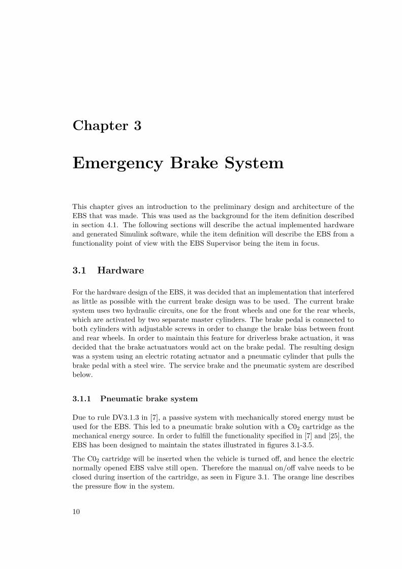
As soon as either an error is detected, low-voltage supply cuts off or the EBS is triggeredin the initial checkup, the EBS valve will open and release the pressure to engage thebrakes. Figure 3.3 shows the pressure flow at this state.
11
Chapter 3. Emergency Brake System
Figure 3.3. Pressure flow when the EBS has been triggered.
The functionality of the EBS will be tested during the initial checkup by triggering theEBS and checking the hydraulic brake pressure. This is done by opening the EBS valveto trigger the brake, followed by closing the valve in order to release the pressure toatmosphere and transition back to EBS "armed"-mode1. The pressure flow when releasingthe brake after initial checkup is seen in Figure 3.4 below.
Figure 3.4. Pressure flow when releasing pressure after the initial checkup.
If the EBS is triggered after the initial checkup due to an error or power loss while drivingon the circuit, there is no possibility to close the EBS valve by putting the signal to highagain. Instead the pressure needs to be released manually by first closing the first manualon/off valve in order to cut the pressure supply. After this, the pressure still present inthe system can be released by opening the second manual on/off valve. See Figure 3.5below.
1The signal to the EBS valve will be put to low/high with the EBS Logic by changing the"Brake_engage_NOT" signal to low/high respectively.
12

3.1. Hardware
Figure 3.5. Pressure flow when the EBS has been disabled in order to release the brakesmanually.
The components used in the pneumatic EBS which are mentioned in figures 3.1-3.5 canbe seen in Figure 3.6 and 3.7.
Figure 3.6. From left: C02 cartridge, pressure regulator, manual on/off valve.
Figure 3.7. From left: pressure sensor, normally opened 3/2 EBS valve, pneumatic cylinder.
13
Chapter 3. Emergency Brake System
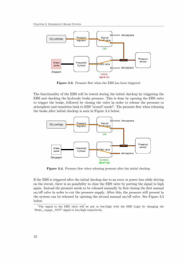
3.1.2 Service brake actuator
An electric servo motor was chosen as the service brake actuator. The intention is thatthe actuator shall be used for longitudinal velocity control during driverless operation.In case of a malfunctioning pneumatic EBS, the service brake will be used as redundantemergency brake.
The servo motor, seen in Figure 3.8, is of model type HS-1005SGT and supplied by HitechMultiplex. The motor has the following specifications, described in Table 3.1.
Table 3.1. Specification of the HS-1005SGT servo motor.
Performance SpecificationsOperating Voltage Range (DC) 11.1 - 14.8 VMaximum Torque Range 84 - 110 kg/cm2
No Load Operating Current Draw 1300 mAStall Current Draw 6500 mADead Band Width 2 µsPhysical SpecificationsDimensions 640 x 330 x 730 mmWeight 363.0 gCircuit Type Digital Amplifier with Mosfet DriveMotor Type 5 Poles Cored Carbon Brushless
Figure 3.8. The electric actuator used as service brake and as redundancy for pneumatic EBS.
3.1.3 Non-programmable logic
In the Formula Student rules [7] it is stated in rule DV3.1.2 that "The vehicle mustbe equipped with an EBS, that is triggered when the shutdown circuit opens using non-programmable logic only (beside monitoring)". The non-programmable, logic referred to
2If using a lever arm of 1 cm, a mass of 84-110 kg can be pulled. This correspond to approx. 840-1100Nm.
14
3.2. Software
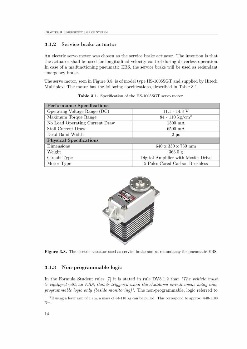
as EBS Logic in the report, is described in the EBS Reference Guide [25]. It consistsof discrete components like standard 74xx logic gates, transistors etc. No processorsor programmable logic parts are included which ensures that the EBS can be triggeredwithout CPU utilization. Figure 3.9 shows the Printed Circuit Board (PCB) where thediscrete components are mounted on. A detailed schematic of the EBS Logic is given inthe item definition in section 4.1 (see Figure 4.3).
Figure 3.9. Schematic of the EBS Logic.
3.2 Software
The software part of the EBS is referred to as the EBS Supervisor and the preliminarydesign was made in reference to the Formula Student rule book [7] as well as the EBSReference Guide [25]. In [25] it is stated that the EBS Supervisor shall include an initialcheckup sequence as well as a continuous monitoring. In addition to these features, aBrake Heading Control (BHC) logic has been added as a solution to prevent potentialunintended yaw while braking. This was done in order to comply with rule DV3.3.3,stating that no intended yaw motion is allowed whilst deceleration during emergencybraking. A collection of relevant Formula Student rules are seen in table A.1 in AppendixA.
The EBS software has been written in MathWorks Simulink environment and the archi-tecture was developed and tested individually before integration to the complete vehiclemodel. The three main parts of the EBS Supervisor are seen in Figure 3.10 togetherwith the interacting elements and signals. The following sections describe each part ofthe software in closer detail.
15

Chapter 3. Emergency Brake System
Figure 3.10. Detailed schematic of the signals to the EBS Supervisor.
3.2.1 Brake heading control
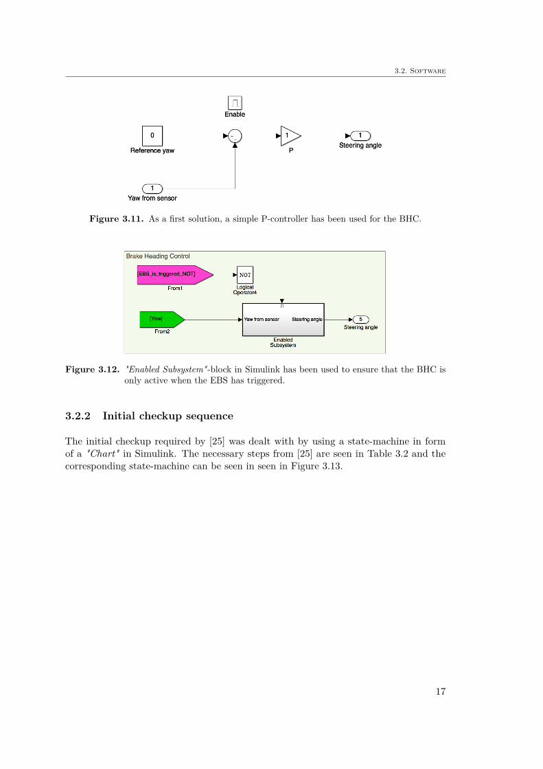
In order to prevent unintended yaw motion whilst decelerating from a triggered EBS,the steering actuator can be utilized to counteract the rotation. A feedback loop as seenin Figure 3.11 with a P-controller is a simple first solution to this problem. This featurewill however only be implemented and further developed if discovered necessary. Thefirst measures to avoid any unintended yaw motion will be to set up a balanced car andincrease the brake bias for the front wheels. This will make the front wheels lock beforethe rear wheels and give a more stable brake heading. If the vehicle would neverthelessrotate during braking, a control loop with an active steering system will be necessary toimplement ans is therefore included in the safety analysis.
The P-controller in Figure 3.11 is only activated when the EBS has triggered by using an"Enabled subsystem"-block in Simulink as seen in Figure 3.12.
16
3.2. Software
Figure 3.11. As a first solution, a simple P-controller has been used for the BHC.
Figure 3.12. "Enabled Subsystem"-block in Simulink has been used to ensure that the BHC isonly active when the EBS has triggered.
3.2.2 Initial checkup sequence
The initial checkup required by [25] was dealt with by using a state-machine in formof a "Chart" in Simulink. The necessary steps from [25] are seen in Table 3.2 and thecorresponding state-machine can be seen in seen in Figure 3.13.
17

Chapter 3. Emergency Brake System
Table 3.2. Initial checkup sequence.
Step Action Description
1 Wait for Shutdown Circuit toclose
Checks that all the relays are closed inthe shutdown circuit in figure 4.5
2 Set "Brake_engage" to high Setting "not brake engage" to high, i.e.do not engage brakes
3Check that
"EBS_is_triggered" signalis active.
"Active" here means that EBS istriggered, which corresponds to low.
4 Activate watchdog signal Start toggling the watchdog signal
5Check that
"EBS_is_triggered" signalis inactive
The EBS should now be inactivatesince watchdog is activated
6 Set "EBS_set_active" to ’0’to activate EBS
Setting "EBS not active" to ’0’, i.e.activate the EBS
7 Check "EBS_is_active" isactive Check that signal value is high
8 Apply brakes through"Brake_engage"
Setting "not brake engage" to low inorder to engage the brakes (pneumatic
EBS)
9 Check brake pressure is builtup as expected
Reading the pressure in the hydraulicbrake lines
10 Release brakesSetting "Brake_engage" to high sothat "not brake engage". Pneumaticpressure released with 3/2 valve.
11 Activate brakes through theredundant system Send brake signal to the service brake
12 Check brake pressure is builtup as expected
Reading the pressure in the hydraulicbrake lines
13 Check "Driving_state_active"is inactive Check that signal value is low
14 Transit to ready state Transit to "AS Ready" according tofigure 4.6
18

3.2. Software
Figure 3.13. State-machine for the initial checkup of the EBS.
19
Chapter 3. Emergency Brake System
3.2.3 Continuous monitoring
The main objective of the EBS Supervisor is to perform continuous monitoring duringoperation to detect typical failures like cable or pneumatic line ruptures. The followingare considered for the continuous monitoring:
• Pneumatic tank pressure• Brake line pressure• Plausibility of sensor signals• Service brake transfer function• Plausibility of non-programmable logic signals• Check "Driving_state_active" is always active while driving
Pneumatic tank pressure check
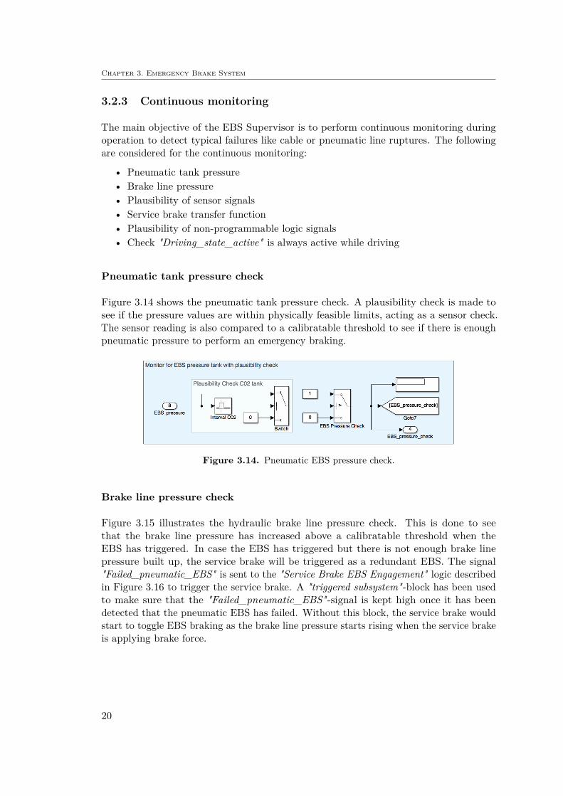
Figure 3.14 shows the pneumatic tank pressure check. A plausibility check is made tosee if the pressure values are within physically feasible limits, acting as a sensor check.The sensor reading is also compared to a calibratable threshold to see if there is enoughpneumatic pressure to perform an emergency braking.
Figure 3.14. Pneumatic EBS pressure check.
Brake line pressure check
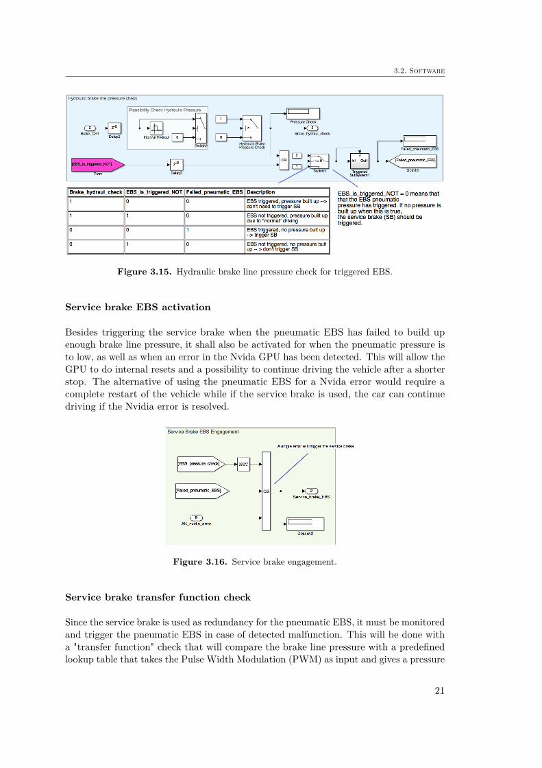
Figure 3.15 illustrates the hydraulic brake line pressure check. This is done to seethat the brake line pressure has increased above a calibratable threshold when theEBS has triggered. In case the EBS has triggered but there is not enough brake linepressure built up, the service brake will be triggered as a redundant EBS. The signal"Failed_pneumatic_EBS" is sent to the "Service Brake EBS Engagement" logic describedin Figure 3.16 to trigger the service brake. A "triggered subsystem"-block has been usedto make sure that the "Failed_pneumatic_EBS"-signal is kept high once it has beendetected that the pneumatic EBS has failed. Without this block, the service brake wouldstart to toggle EBS braking as the brake line pressure starts rising when the service brakeis applying brake force.
20
3.2. Software
Figure 3.15. Hydraulic brake line pressure check for triggered EBS.
Service brake EBS activation
Besides triggering the service brake when the pneumatic EBS has failed to build upenough brake line pressure, it shall also be activated for when the pneumatic pressure isto low, as well as when an error in the Nvida GPU has been detected. This will allow theGPU to do internal resets and a possibility to continue driving the vehicle after a shorterstop. The alternative of using the pneumatic EBS for a Nvida error would require acomplete restart of the vehicle while if the service brake is used, the car can continuedriving if the Nvidia error is resolved.
Figure 3.16. Service brake engagement.
Service brake transfer function check
Since the service brake is used as redundancy for the pneumatic EBS, it must be monitoredand trigger the pneumatic EBS in case of detected malfunction. This will be done witha "transfer function" check that will compare the brake line pressure with a predefinedlookup table that takes the Pulse Width Modulation (PWM) as input and gives a pressure
21
Chapter 3. Emergency Brake System
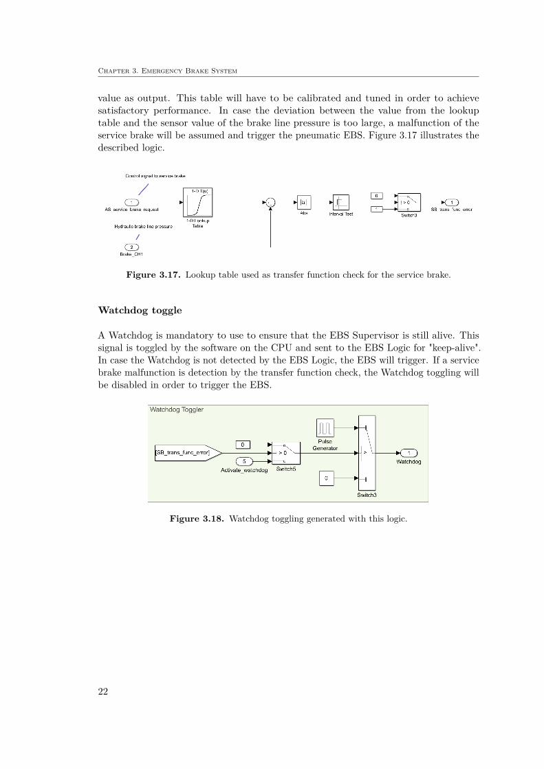
value as output. This table will have to be calibrated and tuned in order to achievesatisfactory performance. In case the deviation between the value from the lookuptable and the sensor value of the brake line pressure is too large, a malfunction of theservice brake will be assumed and trigger the pneumatic EBS. Figure 3.17 illustrates thedescribed logic.
Figure 3.17. Lookup table used as transfer function check for the service brake.
Watchdog toggle
A Watchdog is mandatory to use to ensure that the EBS Supervisor is still alive. Thissignal is toggled by the software on the CPU and sent to the EBS Logic for "keep-alive".In case the Watchdog is not detected by the EBS Logic, the EBS will trigger. If a servicebrake malfunction is detection by the transfer function check, the Watchdog toggling willbe disabled in order to trigger the EBS.
Figure 3.18. Watchdog toggling generated with this logic.
22

3.3. Testing and functionality validation
3.3 Testing and functionality validation
The validation of the EBS was performed step-wise with each component of the softwarebeing developed and tested individually before assembling the complete system. Thealgorithms were designed in MathWorks Simulink which enabled easy Model in the loop(MIL) testing. With the software functionality validated, testing in terms of Processor inthe loop (PIL) was done with an Arduino microcontroller in order to test if the modelcould compile to C-code. At the point of writing this report, no Hardware in the loop(HIL) testing has been performed. The testing and validation was never intended tobe included in this thesis work and will instead be performed subsequently before theFormula Student competition.
23

Chapter 4
Concept Phase
The following chapter describes the safety analysis of the EBS Supervisor made by usingthe main parts from ISO 26262 Part 3 - Concept phase, including item definition, hazardanalysis and risk assessment as well as functional safety concept. The technical safetyconcept is also included, which is a part of ISO 26262 Part 4 - Product development atthe system level. A description of each part is given and then followed by an extract fromthe resulting work product when applying ISO 26262 to the EBS Supervisor.
4.1 Item Definition
The purpose of the item definition is to describe the system or component that shouldbe analyzed. This shall include the item’s functions as well as its dependencies andinteractions with the environment and other items. The item definition results in a workproduct that is used to perform the subsequent phases including the HARA. This sectiondescribes the main parts of the resulting work product of the item definition, whichincludes:
• 4.1.1 Scope of item
• 4.1.2 Item overview on vehicle level
• 4.1.3 Interactions with other items
• 4.1.4 Functional description of related elements
• 4.1.5 Main operation modes and states of the item
• 4.1.6 Functional description of item
• 4.1.7 Environmental conditions
24
4.1. Item Definition
4.1.1 Scope of item
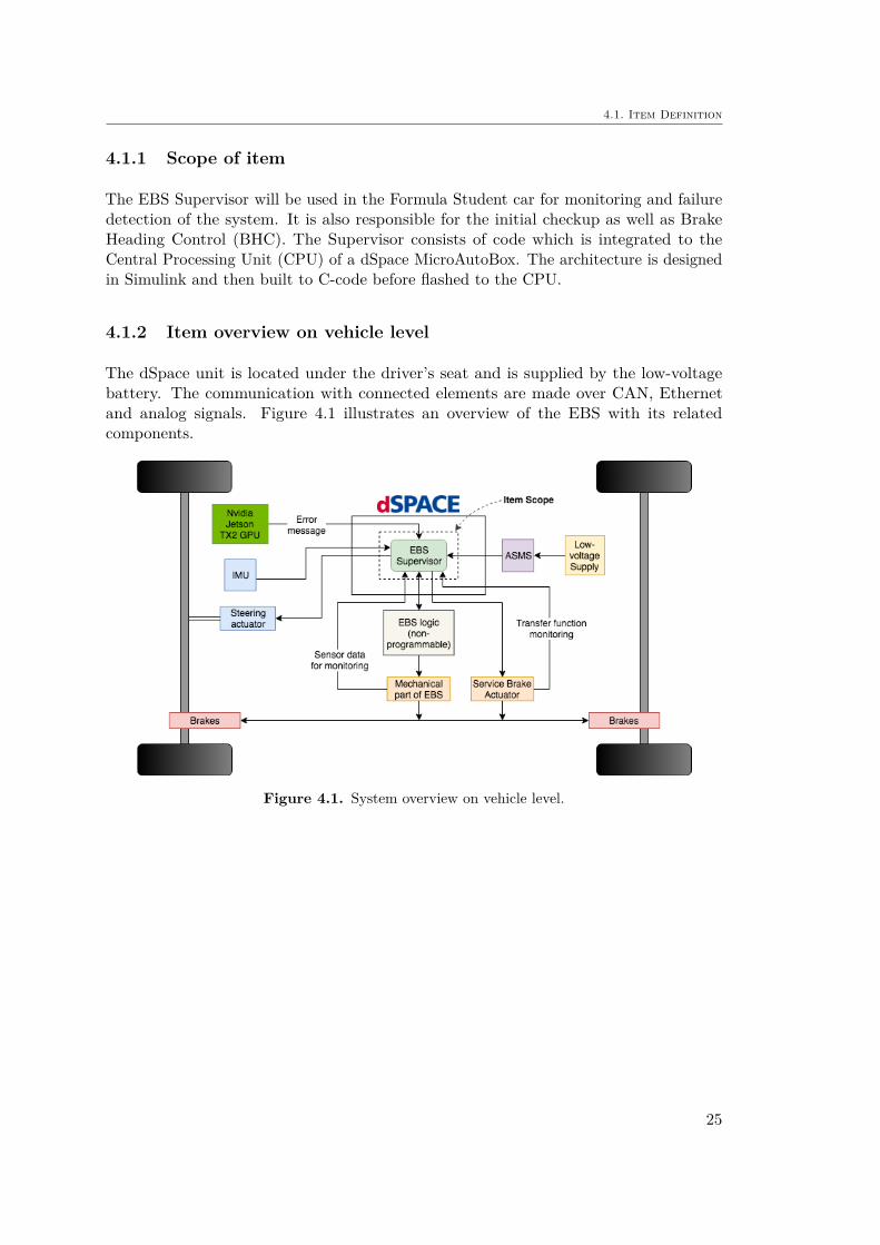
The EBS Supervisor will be used in the Formula Student car for monitoring and failuredetection of the system. It is also responsible for the initial checkup as well as BrakeHeading Control (BHC). The Supervisor consists of code which is integrated to theCentral Processing Unit (CPU) of a dSpace MicroAutoBox. The architecture is designedin Simulink and then built to C-code before flashed to the CPU.
4.1.2 Item overview on vehicle level
The dSpace unit is located under the driver’s seat and is supplied by the low-voltagebattery. The communication with connected elements are made over CAN, Ethernetand analog signals. Figure 4.1 illustrates an overview of the EBS with its relatedcomponents.
Figure 4.1. System overview on vehicle level.
25

Chapter 4. Concept Phase
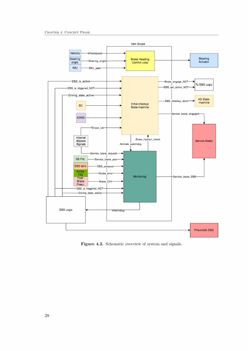
4.1.3 Interaction with other items
Since the EBS Supervisor monitors the entire EBS functionality, a considerable numberof interactions with other items exist. In table 4.1 and 4.2, the input and output signalsof the item are presented. A schematic of the signals and interacting items are presentedin figure 4.2. Note that some of the signals in the tables are represented as Signal_name,where the overline means complement. This could be interpreted as "not", which is whythe signals in figure 4.2 has the added "NOT" to the signal names. The reasoning for thisconvention is safety based. The system needs to continuously communicate for nominalconditions. As soon as a signal like "EBS_is_triggered_NOT" is interrupted, the systemshall assume that the EBS has been triggered and take action.
Table 4.1. Table of input signals to item.
Input Signal From Description
ASMS Low voltage sup-ply
Analog signal to activate the AS, in-cluding EBS Supervisor.
EBS_is_active EBS Logic Shows whether the EBS is in "armed"state or not
EBS_is_triggered EBS LogicDirectly shows the output of the EBSand determines if the system hasbeen triggered or not.
Driving_state_active EBS Logic Displays whether driving stateASMS monitoring is active or not.
EBS_pressure EBS pressure tanksensor
Pressure reading from EBS pressurecontainer
Brake_CH1Hydraulic brakeline pressure sen-sor
Pressure reading from hydraulicbrake line
AS_nvidia_error Nvidia GPU Error message from the Nvidia GPUIMU_yaw IMU Yaw reading from IMU
Wheelspeed Wheelspeedencoder Used as vehicle velocity.
Steering_angle Potentiometer onsteering column Steering angle reading
Shutdown_circuit Shutdown circuit The shutdown circuit signalTorque_val dSpace Traction motor torque request
Service_brake_request dSpace Calculate service brake request fromfeedback controller
Service_brake_pos Service brake po-tentiometer Service brake position reading
26

4.1. Item Definition
Table 4.2. Table of output signals from item.
Output Signal To Description
EBS_set_active EBS Logic Used to set the EBS into “armed”state.
Watchdog EBS Logic
Mandatory to ensure the Supervisoris still alive. This signal must be con-nected to the CPU and periodicallytoggled by software to maintain akeep alive signal, otherwise the EBSgets triggered.
Shutdown_close EBS Logic
Gives the Supervisor the possibilityto activate/deactivate the TractiveSystem (TS) without triggering theEBS. E.g. for enabling the TS beforetransiting to the autonomous system“Ready” state.
Brake_engage EBS Logic
Enables the Supervisor to control thebrake for initial check and to preventthe vehicle from rolling without trig-gering the EBS e.g. during “Ready”state.
BHC_steering Steering actuatorOutput of the Brake Heading Con-trol Loop to counteract vehicle yawpotion
EBS_checkup_done AS State-machine Signal to indicate finished EBScheckup
Service_brake_engaged Service brake Signal to engage the service brakeduring initial checkup
Service_brake_EBS Service brake Signal to trigger the service brakefor emergency
27
Chapter 4. Concept Phase
Figure 4.2. Schematic overview of system and signals.
28
4.1. Item Definition
4.1.4 Functional description of related elements
Bellow follows a short description of the related elements that are connected to the EBSSupervisor.
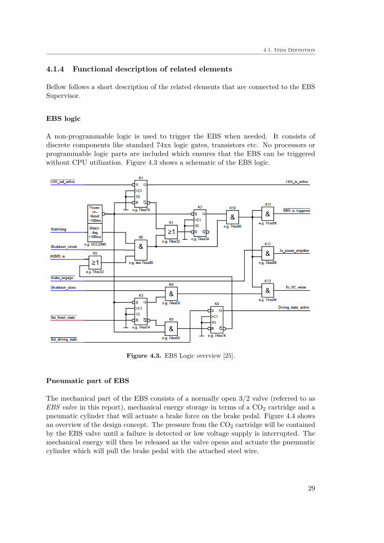
EBS logic
A non-programmable logic is used to trigger the EBS when needed. It consists ofdiscrete components like standard 74xx logic gates, transistors etc. No processors orprogrammable logic parts are included which ensures that the EBS can be triggeredwithout CPU utilization. Figure 4.3 shows a schematic of the EBS logic.
Figure 4.3. EBS Logic overview [25].
Pneumatic part of EBS
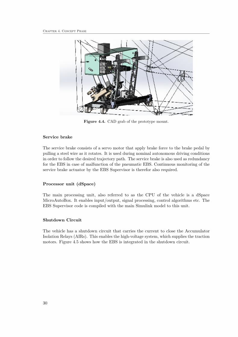
The mechanical part of the EBS consists of a normally open 3/2 valve (referred to asEBS valve in this report), mechanical energy storage in terms of a CO2 cartridge and apneumatic cylinder that will actuate a brake force on the brake pedal. Figure 4.4 showsan overview of the design concept. The pressure from the CO2 cartridge will be containedby the EBS valve until a failure is detected or low voltage supply is interrupted. Themechanical energy will then be released as the valve opens and actuate the pneumaticcylinder which will pull the brake pedal with the attached steel wire.
29
Chapter 4. Concept Phase
Figure 4.4. CAD grab of the prototype mount.
Service brake
The service brake consists of a servo motor that apply brake force to the brake pedal bypulling a steel wire as it rotates. It is used during nominal autonomous driving conditionsin order to follow the desired trajectory path. The service brake is also used as redundancyfor the EBS in case of malfunction of the pneumatic EBS. Continuous monitoring of theservice brake actuator by the EBS Supervisor is therefor also required.
Processor unit (dSpace)
The main processing unit, also referred to as the CPU of the vehicle is a dSpaceMicroAutoBox. It enables input/output, signal processing, control algorithms etc. TheEBS Supervisor code is compiled with the main Simulink model to this unit.
Shutdown Circuit
The vehicle has a shutdown circuit that carries the current to close the AccumulatorIsolation Relays (AIRs). This enables the high-voltage system, which supplies the tractionmotors. Figure 4.5 shows how the EBS is integrated in the shutdown circuit.
30

4.1. Item Definition
Figure 4.5. Schematic of the shutdown circuit in the top, and how the EBS is integrated to it.
ASMS
In order to activate the EBS Supervisor, the Autonomous System Master Switch (ASMS)must be closed. This physical switch activates the autonomous system where the EBSSupervisor is included.
IMU
The vehicle is equipped with an Xsens MTi Inertial Measurement Unit (IMU) that canmeasure the yaw motion of the car. This sensor reading is used for the Brake HeadingControl system, included in the EBS Supervisor.
31

Chapter 4. Concept Phase
Steering Actuator
In order to enable steering actuation, a permanent magnet DC motor is connected to thesteering column. The actuator is used for the BHC feedback loop in order to eliminatepotential yaw motion during braking. A potentiometer attached to the steering columnis used to feed back steering angle position.
Nvida Jetson TX2 GPU
Sensor inputs from LIDAR and camera is used for the computer vision algorithm togenerate a map around the vehicle. From this, the vehicle can also localize itself withthe SLAM algorithm and plan its path around the track with a MPC based trajectoryplanner. In case of any error within the ROS software on the Nvidia GPU, a messageshall be sent to the dSpace CPU and the EBS Supervisor algorithm. This should triggerthe service brake in order to reach a safe state.
4.1.5 Main operation modes and states of the item
The state-flow of the EBS is integrated in the AS state-flow which is described in figure4.6. The relation between the two state-machines is described in table 4.3.
Table 4.3. Table of EBS modes.
Vehicle State EBS State Description
AS Off Unavailable Autonomous systems turned offCheckup EBS checkup procedure
AS Ready Armed Ready to drive, waiting for “GO” signalAS Driving Armed Vehicle driving selected missionAS Finished Armed Vehicle finished with mission
Emergency Brake Triggered Shutdown circuit opened or GLVS supply in-terrupted
32

4.1. Item Definition
Figure 4.6. State-machine for the autonomous system [7].
4.1.6 Functional Description of Item
This section describes the main functionalities of the item. An overview of the functionalityis given as well as the involved elements.
Initial brake engage
When the vehicle is started by turning on the GLVMS and ASMS, the vehicle shallengage the service brake. This is done in order to prevent unintended take-off due toinvoluntary torque request.
Involved external elements
Table 4.4. Involved actuators for initial brake engage.
ActuatorsService brake
33

Chapter 4. Concept Phase
Initial checkup sequence
The initial checkup sequence is performed in order to detect failures that otherwise wouldtrigger the EBS during operation. This includes failures related to misassembly andmissing connections. The checkup sequence consists of the steps described in table 3.2according to Formula Student EBS Reference Guide [25].
Involved external elements
Table 4.5. Involved sensors and inputs for initial checkup sequence.
Sensor/InputAutonomous System Master Switch (ASMS)Shutdown circuitHydraulic brake line pressure sensor
Table 4.6. Involved components for initial checkup sequence.
ComponentsdSpace processorEBS logicEBS valve
Table 4.7. Involved actuators for initial checkup sequence.
ActuatorsService brake
Keep Alive
The EBS Logic is designed in such a way that a single failure results in an emergencybraking. This is done with and-statements and a "keep-alive" structure that requires allsignals set to high in order to keep the EBS valve closed. As soon as one of these signalsare interrupted, the and-statement is not fulfilled which cuts off the signal to the valve.This results in the EBS valve to open and release the mechanically stored brake energy.This logic can be seen in the schematic of the EBS Logic in figure 4.3. The signal thatkeeps the EBS valve closed is To_power_amplifier and the inputs on the left side are theoutputs from the EBS Supervisor as well as the analog signals from shutdown circuit andASMS. The result is that the EBS Supervisor must supply the required signals in orderto maintain the "keep-alive". The required signals that the EBS Supervisor must supplyare EBS_set_active, Watchdog, Brake_engage, Set_finish_state, Shutdown_closeand Set_driving_state.
34

4.1. Item Definition
Involved external elements
Table 4.8. Involved components for keep-alive.
ComponentsdSpace processorEBS logicShutdown circuitEBS valve
Monitoring
The Supervisor shall continuously supervise and monitor for potential failures. Themonitoring shall include:
• Pneumatic tank pressure• Brake line pressure• Plausibility of sensor signals• Service brake transfer function• Plausibility of non-programmable logic signals• Check "Driving_state_active" is always active while driving
Errors or forbidden values for these signals shall result in a triggered EBS.
Involved external elements
Table 4.9. Involved sensors and inputs for monitoring.
Sensors/InputHydraulic brake line pressure sensorEBS pressure tank sensor
Table 4.10. Involved components for monitoring.
ComponentsdSpace processorEBS logicShutdown circuitEBS valve
35

Chapter 4. Concept Phase
Trigger EBS
Most of the potential failures are handled by the EBS logic, which will trigger the brakesby cutting the signal to the EBS valve al release the pneumatic pressure. In case of failuresof the pneumatic EBS, the EBS Supervisor shall engage the service brake actuator instead.Any detected failure shall immediately trigger the service brake. Failures include:
1. Pneumatic tank pressure too low2. Hydraulic brake line pressure not high enough when pneumatic EBS has triggered3. Failure message from Nvidia GPU
The first failure imply that there is not enough stored energy to perform an emergencybraking if needed. The second failure imply that an emergency brake was initiated by thepneumatic EBS, but for some reason the hydraulic brake line pressure has not increasedas expected. This could be due to malfunctioning pneumatic cylinder or EBS valve. Inboth cases, the service brake should perform the emergency braking. The third failureimply that an internal malfunction in the Nvidia GPU has been detected, which shallalso result in a triggered service brake.
There is also the possibility to trigger the pneumatic EBS through the EBS logic byintentionally stopping the watchdog toggling. A situations where this could be usedincludes malfunction detected in the redundant part of EBS (service brake) by a transferfunction check.
Involved external elements
Table 4.11. Involved sensors and inputs.
Sensors/InputHydraulic brake line pressure sensorEBS pressure tank sensor
Table 4.12. Involved components for EBS trigger.
ComponentsdSpace processorEBS logicEBS valve
Table 4.13. Involved actuators/output.
Actuators/outputService brakeCockpit light, ASSI, sound
36
4.1. Item Definition
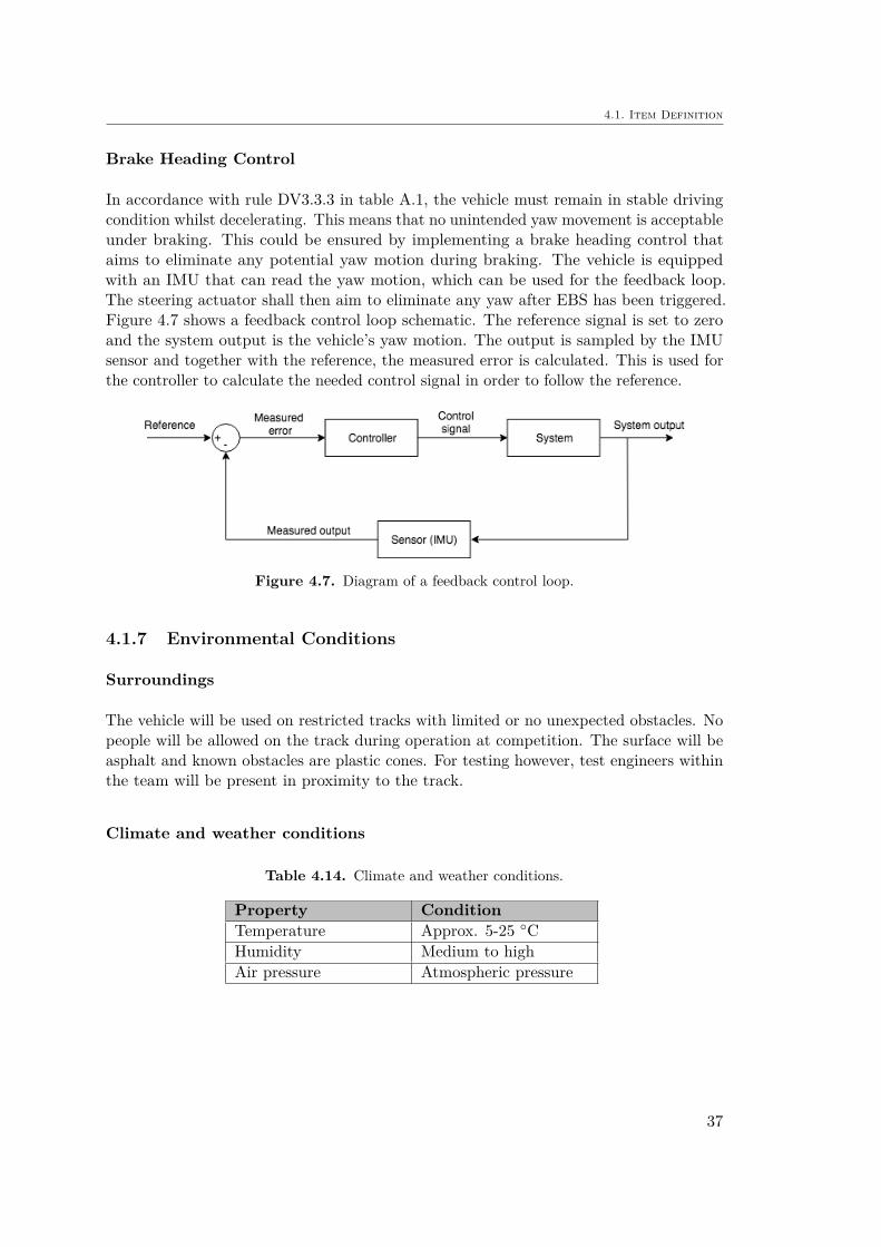
Brake Heading Control
In accordance with rule DV3.3.3 in table A.1, the vehicle must remain in stable drivingcondition whilst decelerating. This means that no unintended yaw movement is acceptableunder braking. This could be ensured by implementing a brake heading control thataims to eliminate any potential yaw motion during braking. The vehicle is equippedwith an IMU that can read the yaw motion, which can be used for the feedback loop.The steering actuator shall then aim to eliminate any yaw after EBS has been triggered.Figure 4.7 shows a feedback control loop schematic. The reference signal is set to zeroand the system output is the vehicle’s yaw motion. The output is sampled by the IMUsensor and together with the reference, the measured error is calculated. This is used forthe controller to calculate the needed control signal in order to follow the reference.
Figure 4.7. Diagram of a feedback control loop.
4.1.7 Environmental Conditions
Surroundings
The vehicle will be used on restricted tracks with limited or no unexpected obstacles. Nopeople will be allowed on the track during operation at competition. The surface will beasphalt and known obstacles are plastic cones. For testing however, test engineers withinthe team will be present in proximity to the track.
Climate and weather conditions
Table 4.14. Climate and weather conditions.
Property ConditionTemperature Approx. 5-25 ◦CHumidity Medium to highAir pressure Atmospheric pressure
37

Chapter 4. Concept Phase
4.2 Hazard Analysis and Risk Assessment (HARA)
The purpose of the HARA is to identify and categorize the hazards that malfunctions inthe item can trigger, and to formulate safety goals which shall prevent or mitigate thehazardous events. This clause uses the item definition as a prerequisite.
The HARA was performed while using an internal AVL spreadsheet template that helpedstreamlined the process. This included a workflow for identifying hazards with a Hazardand Operability Study (HAZOP), evaluating hazardous scenarios as well as classifyingASIL for the safety goals. In the following sections, some extracts from this process hasbeen mirrored to give concrete examples. For the full analysis, please refer to appendicesC-E.
This section will deal with the following:
• 4.2.1 Hazard and Operability Study (HAZOP)
• 4.2.2 Hazardous Scenarios
• 4.2.3 ASIL Classification
• 4.2.4 Safety Goals
4.2.1 Hazard and Operability Study (HAZOP)
When performing the HAZOP, the first step is to identify potential hazards that couldoccur due to malfunctions in the item. Each function described in section 4.1.6 is evaluatedaccording to certain guide words like "NO", "UNINTENDED", "REVERSE", "MORE","LESS", "TOO EARLY" and "TOO LATE" [26]. In table 4.15, an extract from theHAZOP for the EBS Supervisor is shown. To give an example, considering the functionof "Initial Service Brake Engage". Hazards where identified for "NO", "UNINTENDED","LESS" and "TOO LATE" functionality. The same process was repeated for all itemfunctions and can be seen in appendix C. The resulting identified hazards from theHAZOP are summarized in table 4.16.
38

4.2. Hazard Analysis and Risk Assessment (HARA)
Table 4.15. Extract from the Hazard and Operability Study (HAZOP).
Abbrevia-tion offunction
Functionsaccordingto item
definition:
Guideword Hazards Comments
InitialServiceBrakeEngage
Engage theservicebrakeduringinitialcheckup
NO Unintendedtake-off
If torque request is 6= 0and brakes not engaged,unintended take-off
could happenUNIN-
TENDEDUnintendedstandstill
RE-VERSE
Malfunction notapplicable
MORE Malfunction notapplicable
LESS Unintendedtake-off
Not enough braketorque
TOOEARLY
Malfunction notapplicable
TOOLATE
Unintendedtake-off
Did not apply thebrakes in time
Table 4.16. Summary of identified hazards from HAZOP.
Hazard-ID Assumed Hazards CommentH1 unintended take-offH2 unintended standstillH3 unintended braking
H4 loss of brake function No brake force when trying tobrake
H5 loss of brake trigger function Not able to trigger the brakes
H6 unintended long braking distance Included in H4 (less severeversion of H4)
H7 unintended rotationH8 loss of steering
4.2.2 Hazardous Scenarios
With the hazards identified, one shall study these together with scenarios that the vehiclewill be exposed to. The scenarios are classified with the following features:
• Main classification (driving, parking, charging, crash, repair etc.)• Location/type of street (all roads, highway, main road, city area etc)• Traffic/driving situation (normal, curved road, downhill, overtaking etc. )• Speed range (low, normal, high speed)
39
Chapter 4. Concept Phase
• Environmental conditions (normal, wet roads, black ice etc.)• Other particularities (with obstacle, other road users, oncoming traffic etc.)
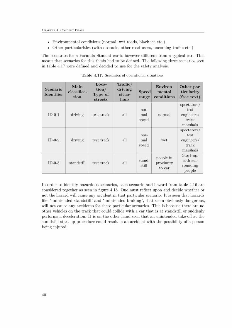
The scenarios for a Formula Student car is however different from a typical car. Thismeant that scenarios for this thesis had to be defined. The following three scenarios seenin table 4.17 were defined and decided to use for the safety analysis.
Table 4.17. Scenarios of operational situations.
ScenarioIdentifier
Mainclassifica-
tion
Loca-tion/
Type ofstreets
Traffic/drivingsitua-tions
Speedrange
Environ-mental
conditions
Other par-ticularity(free text)
ID-0-1 driving test track allnor-malspeed
normal
spectators/test
engineers/track
marshals
ID-0-2 driving test track allnor-malspeed
wet
spectators/test
engineers/track
marshals
ID-0-3 standstill test track all stand-still
people inproximityto car
Start-up,with sur-roundingpeople
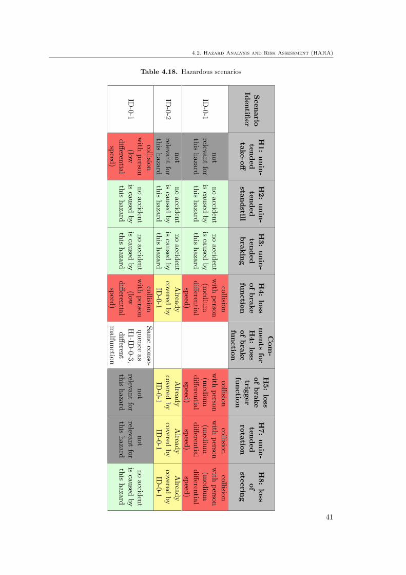
In order to identify hazardous scenarios, each scenario and hazard from table 4.16 areconsidered together as seen in figure 4.18. One must reflect upon and decide whether ornot the hazard will cause any accident in that particular scenario. It is seen that hazardslike "unintended standstill" and "unintended braking", that seem obviously dangerous,will not cause any accidents for these particular scenarios. This is because there are noother vehicles on the track that could collide with a car that is at standstill or suddenlyperforms a deceleration. It is on the other hand seen that an unintended take-off at thestandstill start-up procedure could result in an accident with the possibility of a personbeing injured.
40
4.2. Hazard Analysis and Risk Assessment (HARA)
Table 4.18. Hazardous scenarios
ScenarioIdentifier
H1:
unin-tendedtake-off
H2:
unin-tended
standstill
H3:
unin-tendedbraking
H4:
lossof
brakefunction
Com
-ments
forH4:
lossof
brakefunction
H5:
lossof
braketriggerfunction
H7:
unin-tendedrotation
H8:
lossof
steering
ID-0-1
notrelevant
forthis
hazard
noaccident
iscaused
bythis
hazard
noaccident
iscaused
bythis
hazard
collisionwith
person(m
ediumdifferentialspeed)
collisionwith
person(m
ediumdifferentialspeed)
collisionwith
person(m
ediumdifferentialspeed)
collisionwith
person(m
ediumdifferentialspeed)
ID-0-2
notrelevant
forthis
hazard
noaccident
iscaused
bythis
hazard
noaccident
iscaused
bythis
hazard
Already
coveredby
ID-0-1
Already
coveredby
ID-0-1
Already
coveredby
ID-0-1
Already
coveredby
ID-0-1
ID-0-1
collisionwith
person(low
differentialspeed)
noaccident
iscaused
bythis
hazard
noaccident
iscaused
bythis
hazard
collisionwith
person(low
differentialspeed)
Sameconse-
quenceas
H1-ID
-0-3,different
malfunction
notrelevant
forthis
hazard
notrelevant
forthis
hazard
noaccident
iscaused
bythis
hazard
41

Chapter 4. Concept Phase
4.2.3 ASIL Classification
The Automotive Safety Integrity Level (ASIL) is used to specify the item’s necessaryrequirements of ISO 26262 and safety measures to avoid unreasonable risk. There arefour levels ranging from A-D, with A being the least strict level. The ASIL classificationis a method of quantifying the severity of injuries, the probability of an operationalsituation and the ability to avoid specify harm through the reaction of the involvedpersons. These three categories are denoted severity, exposure and controllability. In thefollowing sections an explanation of the classification is given. The information is basedon "Annex B" in [18].
Severity
The ISO 26262 standard evaluates the severity based on the Abbreviated Injury Scale(AIS) which is issued by the Association for the Advancement of Automotive Medicine(AAAM). There are seven classes of AIS describing the different severity of the injuriesas below:
– AIS 0: no injuries;
– AIS 1: light injuries such as skin-deep wounds, muscle pains, whiplash, etc.;
– AIS 2: moderate injuries such as deep flesh wounds, concussion with up to 15minutes of unconsciousness, uncomplicated long bone fractures, uncomplicated ribfractures, etc.;
– AIS 3: severe but not life-threatening injuries such as skull fractures without braininjury, spinal dislocations below the fourth cervical vertebra without damage tothe spinal cord, more than one fractured rib without paradoxical breathing, etc.;
– AIS 4: severe injuries (life-threatening, survival probable) such as concussion withor without skull fractures with up to 12 hours of unconsciousness, paradoxicalbreathing;
– AIS 5: critical injuries (life-threatening, survival uncertain) such as spinal fracturesbelow the fourth cervical vertebra with damage to the spinal cord, intestinal tears,cardiac tears, more than 12 hours of unconsciousness including intracranial bleeding;
– AIS 6: extremely critical or fatal injuries such as fractures of the cervical vertebraeabove the third cervical vertebra with damage to the spinal cord, extremely criticalopen wounds of body cavities (thoracic and abdominal cavities), etc.
These classes are assessed together with accident statistics in order to determine theinjuries expected to occur for different types of accidents. In table F.1 in appendix F,the examples of severity classification from ISO 26262 are seen. This table can be boileddown to table 4.19 to summarize the classes of severity. For the hazardous scenariosidentified for the EBS Supervisor, severity level S2 and S3 were assigned.
42

4.2. Hazard Analysis and Risk Assessment (HARA)
Table 4.19. Classes of severity
ClassS0 S1 S2 S3
Description No injuriesLight andmoderateinjuries
Severe andlife-threateninginjuries (survival
probable)
Life-threateninginjuries (survivaluncertain), fatal
injuries
Exposure
The probability of exposure is evaluated and given a level from E0 to E4. The lowestlevel E0 is given for highly unlikely or infeasible situations. Examples from ISO 26262includes airplane landing on highway or natural disasters. Note that the exposure isevaluated for the situation that the vehicle is involved in. It is not the hazardous event orthe accident that should be evaluated. For the classes E1-E4, the exposure is evaluatedeither depending on duration of situation or the frequency of occurrence. The mostappropriate exposure rank shall be used for the analysis of situation. In Appendix F,Table F.2 and F.3 illustrate the different exposure rankings. In short, the probability isranked as in table 4.20.
For the situations defined for this thesis (Table 4.17), the exposures were determinedto E3 for ID-0-1 (driving, dry track) and E2 for ID-0-2 (driving, wet track). Since theFormula race car is never operated on normal roads, the classes according to ISO 26262were merely used as a reference. For example, according to Table F.2 a wet road shallresult in E3. However, since the likelihood of operation is lower for wet conditions for arace car compared to a normal car, the exposure was lowered to E2. Operation duringdry road conditions is more likely and is therefore assigned E3.
For ID-0-3 (start-up at standstill) frequency of occurrence was used to give a level ofE4. This is inline with Table F.2 stating that for E4, the frequency of situation "occursduring almost every drive on average".
Table 4.20. Classes of probability of exposure regarding operational situations
ClassE0 E1 E2 E3 E4
Description Incredible Very lowprobability
Lowprobability
Mediumprobability
Highprobability
Controllability
The determination of the controllability class is based on the probability of the driverretaining or regaining control of the vehicle if a hazard were to occur. In Table F.4examples of scenarios and respective controllability classes are given. In Table 4.21 a
43

Chapter 4. Concept Phase
shorter description is given for the classification. Since the investigated vehicle for thisthesis is driverless, it was decided to use the highest level of controllability class C3.
Table 4.21. Classes of controllability
ClassC0 C1 C2 C3
DescriptionControl-lable ingeneral
Simplycontrollable
Normallycontrollable
Difficult tocontrol or
uncontrollable
ASIL Determination
With severity, exposure and controllability determined for each hazardous scenario in table4.18, the ASIL was determined according to Table 4.22. The class Quality Management(QM) imply that there is no requirement to comply with ISO 26262. Instead, theorganization shall refer to its standard methods for quality and safety. For the hazardousscenarios identified for the EBS Supervisor, ASIL C were given. In Table E.1 in AppendixE, the complete analysis of the identified hazardous scenarios is seen.
Table 4.22. ASIL determination
Severity class Probability class Controllability classC1 C2 C3
S1
E1 QM QM QME2 QM QM QME3 QM QM AE4 QM A B
S2
E1 QM QM QME2 QM QM AE3 QM A BE4 A B C
S3
E1 QM QM AE2 QM A BE3 A B CE4 B C D
4.2.4 Safety Goals
For each of the hazardous events with an ASIL assigned to it, a safety goal is determined.These are seen as top-level requirements which are later used to derive the functionalsafety requirements as seen in Figure 4.8. Table 4.23 summarizes the defined safety goalsfrom the hazard and risk analysis in Appendix E.
44

4.2. Hazard Analysis and Risk Assessment (HARA)
Table 4.23. Summary of safety goals from HARA.
Identifier Safety GoalFrom
hazardousevent
ASIL
SG1 Avoid unintended take-off H1 CSG2 Ensure brake functionality H4 CSG3 Ensure brake trigger functionality H5 CSG4 Ensure zero yaw motion during braking H7 CSG5 Ensure steering functionality H8 C
Figure 4.8. Hierarchy of safety goals and functional safety requirements [18].
45
Chapter 4. Concept Phase
4.3 Functional Safety Concept
This section deals with the derivation of the functional safety requirements based onthe safety goals. A background to the safety goals are given as well as the derivedrequirements indicated with FSRx. The prerequisites for the FSC clause is the itemdefinition, the HARA and the SGs. At least one FSR shall be specified for each safetygoal by considering the following in accordance with clause 8.4 in [18]:
– operating mode– fault tolerant time interval3
– safe states– emergency operation interval– functional redundancies
4.3.1 SG1: Avoid unintended take-off
Background information of the safety goal
This safety goals aims to avoid launch upon start-up due to unintended traction motortorque request. The torque request is handled by external items like throttle pedal ortrajectory planner, meaning that the EBS Supervisor cannot affect the torque request.The Supervisor can however apply braking force in order to reach the stated safetygoal.
Time to reach safe state
The safe state for SG1 is defined as "service brake engaged". The Diagnostic TestInterval (DTI) is estimated with expert knowledge within AVL to 50 ms and the FaultReaction Time (FRT) is based on rule DV3.3.1 in [7], stating that the reaction time mustnot exceed 200 ms. This gives a Fault Tolerant Time Interval (FTTI) of 250 ms. Whileassuming an acceleration of approximately 1 g, the vehicle will reach a velocity of lessthan 10 km/h. This should according to [27] result in 0% probability of fatal injuries.Note that these numbers would have to be validated in a later stage of the ISO 26262process.
3See Appendix B for more information. In short it can be described as "time-span in which a fault orfaults can be present in a system before a hazardous event occurs".
46

4.3. Functional Safety Concept
Description of the requirements
Functional Requirement: FSR1
Safety Level: ASIL CDerived From: SG1Operation Mode: Startup
EBS Supervisor shall monitor traction motor torque request and service brake activationduring startup and execute system reactions for detected errors.
4.3.2 SG2: Ensure brake functionality
Background information of the safety goal
The EBS Supervisor should ensure the brake functionality by constantly monitor for po-tential malfunctions. In case of emergency, the vehicle must always be able to stop.
Time to reach safe state
The safe state for SG2 is defined as ”redundant brake engaged” . With 50 ms forDTI and rule-based requirement of a FDT less than 200 ms, a FTTI of 250 ms isdetermined.
Description of the requirements
Functional Requirement: FSR2
Safety Level: ASIL CDerived From: SG2Operation Mode: EBS Armed
Monitoring of brake system components needs to be guaranteed. This includes:
– Pneumatic tank pressure– Brake line pressure– Service brake position request (input)– Service brake position (output)
47
Chapter 4. Concept Phase
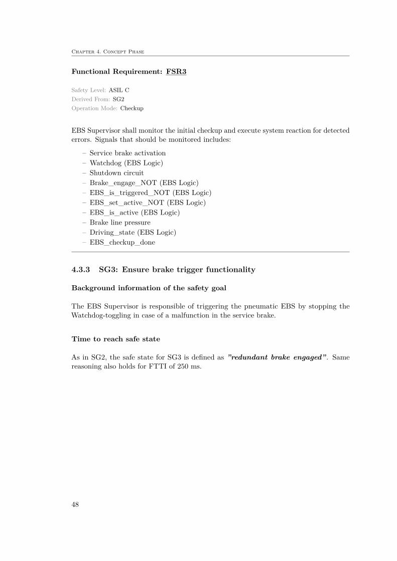
Functional Requirement: FSR3
Safety Level: ASIL CDerived From: SG2Operation Mode: Checkup
EBS Supervisor shall monitor the initial checkup and execute system reaction for detectederrors. Signals that should be monitored includes:
– Service brake activation– Watchdog (EBS Logic)– Shutdown circuit– Brake_engage_NOT (EBS Logic)– EBS_is_triggered_NOT (EBS Logic)– EBS_set_active_NOT (EBS Logic)– EBS_is_active (EBS Logic)– Brake line pressure– Driving_state (EBS Logic)– EBS_checkup_done
4.3.3 SG3: Ensure brake trigger functionality
Background information of the safety goal
The EBS Supervisor is responsible of triggering the pneumatic EBS by stopping theWatchdog-toggling in case of a malfunction in the service brake.
Time to reach safe state
As in SG2, the safe state for SG3 is defined as ”redundant brake engaged” . Samereasoning also holds for FTTI of 250 ms.
48

4.3. Functional Safety Concept
Description of the requirements
Functional Requirement: FSR4
Safety Level: ASIL CDerived From: SG3Operation Mode: EBS Armed/triggered
EBS Supervisor shall monitor and execute system reaction for brake trigger signals. Thisincludes:
– Watchdog signal– Nvidia error– Brake line pressure– EBS_is_triggered_not
Functional Requirement: FSR5
Safety Level: ASIL CDerived From: SG3Operation Mode: EBS Armed
The EBS Supervisor shall monitor the service brake transfer function check and executesystem reaction to detected errors.
4.3.4 SG4: Ensure zero yaw motion during braking
Background information of the safety goal
Upon braking, the car should not have any unintended rotation. This will be achievedwith a feedback controller described in the item definition. This safety goals aims toguarantee the functionality of such system.
Time to reach safe state
DTI is estimated to 50 ms as for previous safety goals. The safe state is defined as "yawmotion < 0.x4rad/s". FRT of 50 ms is estimated giving a FTTI of 100 ms.
4A value needs to be specified and validated to determine what level of yaw is considered safe.
49
Chapter 4. Concept Phase
Description of the requirements
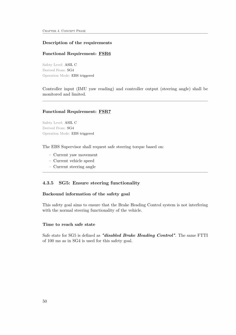
Functional Requirement: FSR6
Safety Level: ASIL CDerived From: SG4Operation Mode: EBS triggered
Controller input (IMU yaw reading) and controller output (steering angle) shall bemonitored and limited.
Functional Requirement: FSR7
Safety Level: ASIL CDerived From: SG4Operation Mode: EBS triggered
The EBS Supervisor shall request safe steering torque based on:
– Current yaw movement– Current vehicle speed– Current steering angle
4.3.5 SG5: Ensure steering functionality
Backound information of the safety goal
This safety goal aims to ensure that the Brake Heading Control system is not interferingwith the normal steering functionality of the vehicle.
Time to reach safe state
Safe state for SG5 is defined as "disabled Brake Heading Control". The same FTTIof 100 ms as in SG4 is used for this safety goal.
50
4.3. Functional Safety Concept
Description of the requirements
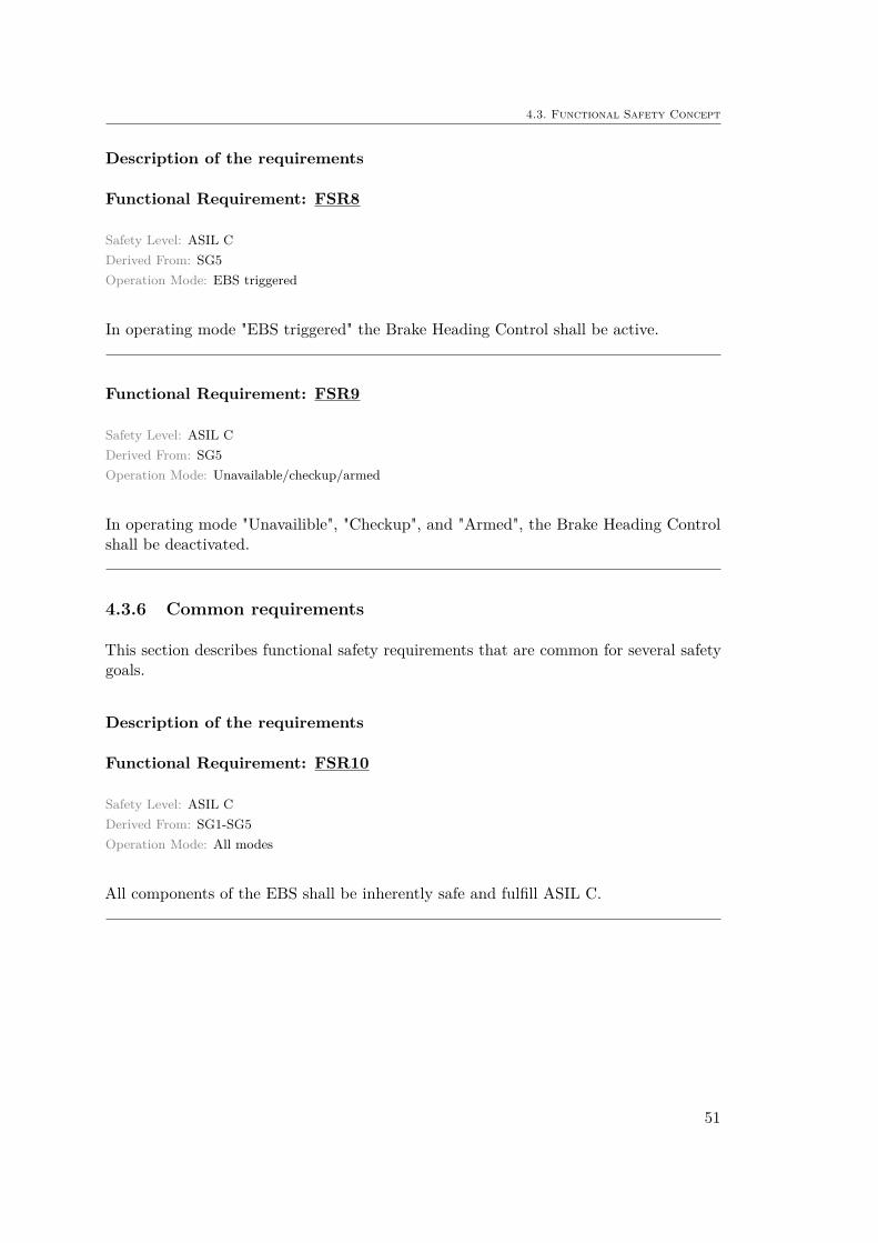
Functional Requirement: FSR8
Safety Level: ASIL CDerived From: SG5Operation Mode: EBS triggered
In operating mode "EBS triggered" the Brake Heading Control shall be active.
Functional Requirement: FSR9
Safety Level: ASIL CDerived From: SG5Operation Mode: Unavailable/checkup/armed
In operating mode "Unavailible", "Checkup", and "Armed", the Brake Heading Controlshall be deactivated.
4.3.6 Common requirements
This section describes functional safety requirements that are common for several safetygoals.
Description of the requirements
Functional Requirement: FSR10
Safety Level: ASIL CDerived From: SG1-SG5Operation Mode: All modes
All components of the EBS shall be inherently safe and fulfill ASIL C.
51
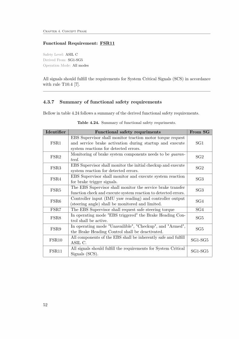
Chapter 4. Concept Phase
Functional Requirement: FSR11
Safety Level: ASIL CDerived From: SG1-SG5Operation Mode: All modes
All signals should fulfill the requirements for System Critical Signals (SCS) in accordancewith rule T10.4 [7].
4.3.7 Summary of functional safety requirements
Bellow in table 4.24 follows a summary of the derived functional safety requirements.
Table 4.24. Summary of functional safety requriments.
Identifier Functional safety requriments From SG
FSR1EBS Supervisor shall monitor traction motor torque requestand service brake activation during startup and executesystem reactions for detected errors.
SG1
FSR2 Monitoring of brake system components needs to be guaran-teed. SG2
FSR3 EBS Supervisor shall monitor the initial checkup and executesystem reaction for detected errors. SG2
FSR4 EBS Supervisor shall monitor and execute system reactionfor brake trigger signals. SG3
FSR5 The EBS Supervisor shall monitor the service brake transferfunction check and execute system reaction to detected errors. SG3
FSR6 Controller input (IMU yaw reading) and controller output(steering angle) shall be monitored and limited. SG4
FSR7 The EBS Supervisor shall request safe steering torque SG4
FSR8 In operating mode "EBS triggered" the Brake Heading Con-trol shall be active. SG5
FSR9 In operating mode "Unavailible", "Checkup", and "Armed",the Brake Heading Control shall be deactivated. SG5
FSR10 All components of the EBS shall be inherently safe and fulfillASIL C. SG1-SG5
FSR11 All signals should fulfill the requirements for System CriticalSignals (SCS). SG1-SG5
52

4.4. Technical Safety Concept
4.4 Technical Safety Concept
The objective of the TSC is to refine the FSRs into more technically detailed requirements.As can be seen in Figure 4.8, there can be several requirements for one SG. The sameholds for the derivation of TSRs from FSRs. With 11 FSRs, the resulting number ofTSRs were considered too many to include in the main body of the report. Instead, onlythe requirements from SG1 are included here with the complete list of TSRs seen inAppendix G.
The technical safety concept is based on the work products from Part 3: Concept phase.Bellow follows the information that shall be available. The number refers to the clausein the standard.
• Functional safety concept in accordance with ISO 26262-3:2011, 8.5.1• Validation plan in accordance with ISO 26262-4:2011, 5.5.4
Not considered in this project
The following information can also be considered:
• Safety goals (ISO 26262-3:2011, 7.5.2)• Functional concept of item (from external source, ISO 26262-3:2011, 5.4.1)
EBS Reference Guide [25]• Prel. architectural assumptions (from external source, ISO 26262-3:2011, 8.3.2)
Not available in this project
Below follows the derived technical safety requirements for SG1 as well as the definedgeneral requirements. This is followed by a proposed three level architecture and designin order to comply with the safety requirements.
4.4.1 SG1: Avoid unintended take-off
Technical Requirement: TSR1
Safety Level: ASIL CDerived From: FSR1Operation Mode: Startup
The MicroAutoBox shall continuously read:
– Torque request (Torque_request)– Service brake engage signal (Service_brake_engage)– EBS checkup done signal (EBS_checkup_done)
53

Chapter 4. Concept Phase
Technical Requirement: TSR2
Safety Level: ASIL CDerived From: FSR1Operation Mode: Startup
If EBS_checkup_done = 0, and torque value 6= 0, the service brake shall be engaged bysetting Service_brake_engage signal to high.
4.4.2 General Requirements
When considering a three level monitoring concept, the third level is described as acontroller monitoring level. This aims to monitor the processor with an independentmonitoring module including:
– AD monitoring– Program flow check– Standard ROM check– Cyclic RAM check– Cyclic configuration check– Cyclic ROM check– Instruction set tests– Monitoring unit response test– Standard RAM check– Q/A check– Fault reaction
These checks provide requirements of monitoring undervoltage/overvoltage of microcon-trollers, having fault counters for ADC operations and RAM checks, reset triggering dueto detection of defective ROM etc. These are all important requirements and would benecessary to implement in order to fulfill the target ASIL C level. This is however be-yond the scope of this paper and will be left as a recommendation for future improvements.
4.4.3 Considered hardware architecture
The major components of the EBS Supervisor is the MicroAutoBox microprocessor anda monitoring unit. The MicroAutoBox performs the level 1 EBS Supervisor function andthe level 2 safety software. The monitoring unit which runs on a separate power supplyand clock sources will be used to perform the level 3 processor monitoring.
54
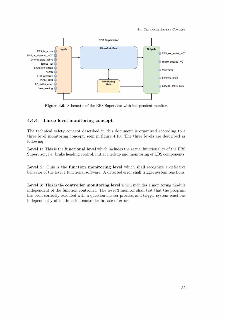
4.4. Technical Safety Concept
Figure 4.9. Schematic of the EBS Supervisor with independent monitor.
4.4.4 Three level monitoring concept
The technical safety concept described in this document is organized according to athree level monitoring concept, seen in figure 4.10. The three levels are described asfollowing:
Level 1: This is the functional level which includes the actual functionality of the EBSSupervisor, i.e. brake heading control, initial checkup and monitoring of EBS components.
Level 2: This is the function monitoring level which shall recognize a defectivebehavior of the level 1 functional software. A detected error shall trigger system reactions.
Level 3: This is the controller monitoring level which includes a monitoring moduleindependent of the function controller. The level 3 monitor shall test that the programhas been correctly executed with a question-answer process, and trigger system reactionsindependently of the function controller in case of errors.
55

Chapter 4. Concept Phase
Figure 4.10. Schematic of the three level safety concept [28].
56

Chapter 5
Results
5.1 RQ1: How shall the EBS be design for KTH FS?
This question was aimed to give an answer to how the final design of the required EBSwas to be made. The answer could have been different depending on the outcome ofthe functional safety analysis. If the analysis with ISO 26262 had resulted in safetyrequirements that were considered feasible to implement, the design of the EBS wouldhave been changed accordingly and would have differed from the preliminary design seenin Chapter 3. However, since the safety analysis gave requirements of redundancy thatwere too demanding in terms of time and cost, the design of the EBS was preserved asthe preliminary design. It is concluded that as long as the design follows the FormulaStudent rules, it is considered adequately safe.
5.2 RQ2: What are the measures for functional safety?
This question is rather open and a complete answer would require a report in its own.The answer can instead partially be found in Chapter 2 and 4, which describes parts fromthe process of ISO 26262. The question can thereby be answered with what measures forfunctional safety there are for the concept phase of ISO 26262. This includes the use ofitem definition, HARA, FSC and TSC as described below.
The item definition will allow a common understanding of the system being analyzed.By having a mutual understanding within the functional safety team or between OEMsand Tier 1 suppliers, the subsequent phases will require less discussions. The nextstep with the HARA allow an understanding of what potential hazards that couldarise with malfunction of item functionality. One can from this define the safety goalsaiming to mitigate or avoid unreasonable risk. These goals are then used to definefunctional safety requirements which are refined into the technical safety requirement.Following this process brings several benefits. One aspect is that a documentation withtraceability is generated that can be used to follow design choices. Another aspect isthat a comprehensive analysis of the system is performed, leading to improved safety
57
Chapter 5. Results
solutions. A crucial part of this process is that the analysis is carried out by peopledifferent than the ones developing the system. The analysis must also be performed byseveral individuals in order to give different inputs and perspectives.
Worth mentioning here is that the ISO 26262 standard is evaluating malfunction inan item’s function and aims to mitigate any hazards this could lead to. The standarddoes however not question whether or not that function is a good solution in the firstplace. Those choices shall already have been analyzed with system safety in an earlierphase.
5.3 RQ3: What potential faults, hazards and risks in theEBS are relevant for the Formula Student application?
By performing the Hazard Analysis and Risk Assessment according to ISO 26262, severalpotential faults, hazards and risks could be identified. It was however discovered that notall of these hazards were relevant for the Formula Student application. With a closedoff track without other vehicles running simultaneously during competition, the numberof potential hazardous scenarios became limited. It was discovered that unintendedstandstill or braking would not cause any hazardous scenario since no other vehicles couldrisk a collision. These arguments hold when discussing injuries to people, but one couldchange the perspective to a competition score standpoint. In this regard, an unintendedstandstill or braking would result in a disqualification. To avoid or mitigate the risk ofthis scenario, one could argue that extra measures for safety should be taken after all.The ISO 26262 standard is only supposed to be used to mitigate risks of injuries, butcould nevertheless be used as a tool to mitigate risk of disqualification or penalties inFormula Student.
5.4 RQ4: Is the EBS fulfilling the ISO 26262 standard?
From the resulting work products for FSC and TSC in Chapter 2 it is seen that extensivesafety measures are needed in order to fulfill the defined ASIL. In order to guaranteethe functionality of the EBS, there is a need for implementing redundancy of an extraCPU and signal checks to see if random hardware faults or systematic errors are present.Another aspect to address would be the Brake Heading Control with some necessary failoperational strategy in case the feedback loop would malfunction. With the choice of notimplementing the result of the ISO 26262 analysis, the EBS would not fulfill the criteriaset by the standard.
58
5.5. RQ5: Can ISO 26262 be a useful standard for KTH FS to implement in their work process?
5.5 RQ5: Can ISO 26262 be a useful standard for KTHFS to implement in their work process?
The process of applying ISO 26262 for the EBS has proven to be largely informativeand that it increases one’s perception of safety. With safety being a key point that theFormula Student judges evaluate during competition, an analysis with ISO 26262 willgive credibility to the design. It has however been discovered that the process of followingthe standard is considerable time consuming. For a project like Formula Student wherethe time is limited to construct what is merely a prototype, the standard seems excessive.The process has nevertheless inspired some implemented design choices for the EBSsoftware since a lot of reflection was done regarding the safety of the system.
59

Chapter 6
Discussion and Conclusions
This chapter provide some discussions and conclusions regarding the results from theprevious chapters as well as to the thesis work in general. Some future recommendationsand improvements are also given.
6.1 Documentation
Although ISO 26262 gives explanations and examples of what to include for each workproduct of item definiton, HARA, FSC and TSC, it is not stated how they should bestructured. It is up to each organization to decide for themselves in order to allowintegration of their already incorporated methods. The documentation of the workproducts will largely depend on the used requirements management tool. For this work,no such tool was used and instead the documentation was done directly in LaTeX sincethe final results were to be presented in a LaTeX-made document. In retrospective, arequirements management tool would have made the process less time consuming andallowed for better traceability.
6.2 Level of detail
Besides uncertainties regarding documentation, the level of detail that should be usedfor each work product was also a concern. For each step starting from SGs, FSRs andTSRs the level of detail shall be refined, but it is not clear how, i.e. how should theresolution of detail change for each step. From available papers that include results fromeach work product, different approaches were used. The report by [11] starts with moregeneral SGs, while [10] defined detailed SGs and continued with even more detailed FSRand TSR. The first approach of keeping the SG more general was used in this thesissince it resembled the methods used within AVL. Since ISO 262626 also states that theSGs should be the top-level safety requirements, a open definition of SGs seemed morereasonable.
60

6.3. ASIL Classification
6.3 ASIL Classification
The process of classifying the ASIL is a way to quantify the qualitative features of severity,exposure and controllability. This enables easier comparison and labeling but the processnaturally brings some issues. The way ISO 26262 aim to quantify the data, is by usingstatistics from accident records. One could also use data from experiments in a safeenvironment like an advanced driving simulator. However, in this thesis with a driverlessvehicle, neither of stated options were possible. Instead, an estimation of the classesfor severity, exposure and controllability was done from the available examples in thestandard. From clause 7.4.3.1 in [18] it is stated that when finding a classification difficultto make due to doubt, one should give a higher ASIL rather than a lower. For this worksome doubts did exist which made the ASIL alternate between ASIL B and ASIL C,resulting in ASIL C due to the statement above.
Another aspect to consider for the ASIL classification is the chosen level of detail for theoperational situations. A very detailed list of operational situations for a hazard, withregards to vehicle state, road conditions and environmental conditions, can lead to aninappropriate lowering of the ASIL. ISO 26262 does in clause 7.4.4.2 in [18] state that "itshall be ensured that the chosen level of detail of the list of operational situations doesnot lead to an inappropriate lowering of the ASIL of the corresponding safety goals". Howone ensures this is however left unsaid, but by being aware and reflecting upon it, mightbe enough to benefit the safety analysis.
6.4 ISO 26262 for Autonomous Systems
The 2011 first edition of the ISO 26262 standard is intended to be applied to E/E systemsin "...series production passenger cars..." and "...does not address unique E/E systemsin special purpose vehicles...". The Formula Student car is neither a series productioncar and it does have unique E/E systems. The use of ISO 26262 could nevertheless bebeneficial and the fact is that no real issues concerning this occurred during the project.By defining new operational scenarios it was still possible to classify severity, exposureand controllability.
Something that did however create issues was that the standard does not addressautonomous systems. This was seen when the controllability for the ASIL classificationwas done. Since the controllability is evaluated depending on the drivers ability toreact and regain control of a situation, the classification for a driverless vehicle is moreproblematic. One approach to this problem could be to instead evaluate the ability of thevehicle’s trajectory planner to regain control for hazardous scenarios. This would requirea rigorous investigation and would likely require simulation as well as track tests. Forthe KTH FS vehicle, the trajectory planner is designed to follow a reference line definedbetween the track cones. As for now, no advanced functionality to avoid obstacles andhazards exists, leading to the highest class of controllable for the ASIL classification.However, for a more advanced trajectory planner, the controllability class could belowered if it is possible to prove that it can handle certain hazardous scenarios.
61

Chapter 6. Discussion and Conclusions
6.5 Quality Management
For the cases where severity, exposure and controllability are low enough, QM is given asseen in Table 4.22. This does not mean that the system is considered safe but soley implythat extra measures in terms of ISO 26262 is not required. Instead the organizationsordinary quality and safety assessments shall be perform. This still puts high demandsand is according to [29] what OEMs usually fail to fulfill. In the case of KTH FS, the QMcan be considered to comply with the FS rules. Hence, QM classification still imply thatsafety measures are to be taken, just not necessarily in accordance with ISO 26262.
6.6 The EBS Supervisor as an Item
The main problem and difficulty throughout this thesis has been regarding the EBSas an item to analyze. Since it is a safety critical feature of the vehicle, the FormulaStudent organizers have already put effort into making the system safe. This has beendone by implementing the continuous monitoring feature which shall oversee the brakefunctionality. Since the introduction of a monitoring feature usually is the result of theISO 26262 analysis, some complications emerged.
To better understand how, an example of a Vehicle Control Unit (VCU) can be used. Themain function of a VCU is to convert driver inputs to a acceleration and torque requestfrom the motor. In order to ensure the functionality of such unit, a monitoring unit canbe implemented to oversee the torque request sent to the motor. Monitoring in this casecould be to inhibit traction motor torque depending on current vehicle speed, gear shiftposition etc. This monitoring would correspond to the level 2 function monitoring asseen in Figure 4.10.
With the EBS Supervisor however, a monitor is already implemented in the level 1functionality. This means that a level 2 function monitor would work as a redundantmonitoring to make sure that the level 1 monitoring has been performed correctly. Thisis, as already stated, excessive safety measures for the Formula Student application. In aseries production vehicle it would however be necessary since there could be potentialerrors in the level 1 function due to corrupt inputs or incorrect software coding.
Although this difficulty added some confusion during the process of the analysis, ithas nevertheless given a deeper insight to functional safety due to the needed extraefforts.
6.7 Further Work and Improvements
As always, a number of improvements and ideas for future work arises as the resourcesof time are diminishing. To start with, one could continue the process of the ISO26262 analysis to see what the subsequent parts would contribute. In terms of the EBSdesign, the Brake Heading Control could be developed by performing simulations in IPG
62

6.7. Further Work and Improvements
CarMaker. This could result in a tuned and validated controller to ensure zero yawduring emergency braking.
To further validate the safety of the EBS, tools like Failure Modes and Effects Analysis(FMEA) as well as Fault Tree Analysis (FTA) could be used. These methods couldpotentially give new insights to the design and contribute with further safety features. Inaddition to this, one could look into the new standard under development called Safety ofthe Intended Functionality (SOTIF) [30]. With electronic systems becoming increasinglycomplex, the area of functional safety continues to expand. As autonomous systems areintroduced to series production vehicles, safety standards will be essential and most likelylegislated.
63
References
[1] (2010). Automobile History, [Online]. Available: https://www.history.com/topics/automobiles (visited on 04/16/2018).
[2] A. Stensson, Aspects on transportation, KTH.[3] (2017). World Health Organization - The top 10 causes of death, [Online]. Avail-
able: http://www.who.int/mediacentre/factsheets/fs310/en/ (visited on04/01/2018).
[4] S. Forward, “Driving Violations - Investigating Forms of Irrational Rationality”,PhD thesis, 2008.
[5] (2017). VTI - Mänskliga faktorn, [Online]. Available: https://www.vti.se/sv/nyhetsarkiv/nyhetsarkiv/ny- avhandling- om- manskliga- faktorn- bakom-trafikolyckor-/ (visited on 05/08/2018).
[6] (2018). About Formula Student, [Online]. Available: https://www.imeche.org/events/formula-student/about-formula-student (visited on 05/02/2018).
[7] Formula student rules version 1.1, Formula Student Germany, 2018.[8] M. Ito and K. Kishida, “An approach to manage the concept phase of iso 26262”,
Journal of Software: Evolution and Process, vol. 26, no. 9, pp. 829–836, 2014.[9] P. Sinha, “Architectural design and reliability analysis of a fail-operational brake-by-
wire system from iso 26262 perspectives”, eng, Reliability Engineering and SystemSafety, vol. 96, no. 10, 2011.
[10] P. Gradin and V. Ortman, Development of a Collision Avoidance Truck Systemfrom a Functional Safety Perspective, 2011.
[11] D. Johansson and P. Karlsson, Safety mechanisms for random ECU hardwarefailures in compliance with ISO 26262, 2015.
[12] X. Iturbe, B. Venu, J. Jagst, E. Ozer, P. Harrod, C. Turner, and J. Penton,“Addressing functional safety challenges in autonomous vehicles with the arm tcl sarchitecture”, eng, Design & Test, IEEE, vol. 35, no. 3, pp. 7–14, 2018.
[13] G. Schildbach, “On the application of iso 26262 in control design for automatedvehicles”, eng, Electronic Proceedings in Theoretical Computer Science, vol. 269,pp. 74–82, 2018.
[14] T. Grüne-Yanoff, “Philosophy of Technology, TaMoS Lecture #6”, 2018.[15] K. Adams, Non-functional Requirements in Systems Analysis and Design. Springer
Verlag, 2015, ch. 2.[16] T. L. Ferris, “Engineering design as research”, in Research Methodologies, Innova-
tions and Philosophies in Software Systems Engineering and Information Systems.Oxford: IGI Global, 2012, ch. 20.
64
[17] S. Hulley, S. Cummings, and W. Browner, Designing Clinical Research, 3rd ed.Philadelphia (PA): Lippincott Williams and Wilkins, 2007.
[18] ISO 26262 "Road vehicles - Functional safety", Part 3: Concept phase, 2011.[19] ISO 26262 "Road vehicles - Functional safety", Part 4: Product development at the
system level, 2011.[20] H.-L. Ross, Functional Safety for Road Vehicles. Springer Nature, 2016.[21] (2018). International Electrotechnical Commission - Functional Safety and IEC
61508, [Online]. Available: http://www.iec.ch/functionalsafety/ (visited on05/28/2018).
[22] ISO 26262 "Road vehicles - Functional safety", Part 1: Vocabulary, 2011.[23] (2014). National Instruments - What is the ISO 26262 Functional Safety Standard?,
[Online]. Available: http://www.ni.com/white-paper/13647/en/#toc1 (visitedon 05/20/2018).
[24] ISO 26262 "Road vehicles - Functional safety", Part 2: Management of functionalsafety, 2011.
[25] M. Stollberger, EBS Reference Guide, Formula Student Germany, 2017.[26] S. of New South Wales, Hazardous Industry Planning Advisory Paper No 8 (HAZOP
Guidelines). New South Wales, Australia: The Department of Planning, 2011.[27] (2018). European Commission - Speed and the injury risk for different speed
levels, [Online]. Available: https://ec.europa.eu/transport/road_safety/specialist/knowledge/speed/speed_is_a_central_issue_in_road_safety/speed_and_the_injury_risk_for_different_speed_levels_en (visited on04/26/2018).
[28] J. Koller, AVL - Three level safety concept, 2017.[29] A. Johansson, Interview regarding functional safety at Scania, 2018.[30] (2018). ISO/WD PAS 21448 Road vehicles - Safety of the intended functionality,
[Online]. Available: https://www.iso.org/standard/70939.html (visited on06/11/2018).
[31] (2016). KVA - How Can We Specify Safety-Critical Time Intervals?, [Online].Available: https://www.kvausa.com/can-specify-safety-critical-time-intervals/ (visited on 04/20/2018).
65

Appendix A
Formula Student Rules
Table A.1. Table of relevant Formula Student rules.
Rule Description
D2.6.2If the vehicle does not enter “AS Ready” state within 1 min afterbeing staged, the team may be sent back to the preparation areaby the officials.
D2.6.5 The EBS may be armed already in the preparation area.
DV3.1.2The vehicle must be equipped with an EBS, that is triggered whenthe shutdown circuit opens using non-programmable logic only(beside monitoring).
DV3.1.3The EBS must only use passive systems with mechanical energystorage. Electrical power loss at EBS must lead to a direct emer-gency brake maneuver.
DV3.1.4 The EBS may be part of the hydraulic brake system.
DV3.2.1Due to the safety critical character of the EBS, the system musteither remain fully functional, or the vehicle must automaticallytransition to the safe state in case of a single failure mode.
DV3.2.2 The safe state is the vehicle at a standstill, brakes engaged toprevent the vehicle from rolling, and an open shutdown circuit.
DV3.2.5 The service brake system may be used as redundancy if two-waymonitoring is ensured.
DV3.2.6A red indicator light in the cockpit that is easily visible even inbright sunlight and clearly marked with the lettering “EBS” mustlight up if the EBS detects a failure.
DV3.3.1 The system reaction time (the time between entering the triggeredstate and the start of the deceleration) must not exceed 200 ms.
Table continued on next page
66

DV3.3.2 The average deceleration must be greater than 8 m/s2 under drytrack conditions.
DV3.3.3
Whilst decelerating, the vehicle must remain in a stable drivingcondition (i.e. no unintended yaw movement). This can be eithera controlled deceleration (steering and braking control is active) ora stable braking in a straight line with all four wheels locked.
IN6.3.3
During the brake test, the vehicle must accelerate in autonomousmode up to at least 40 km/h within 20 m. From the point wherethe RES is triggered, the vehicle must come to a safe stop withina maximum distance of 10 m.
67
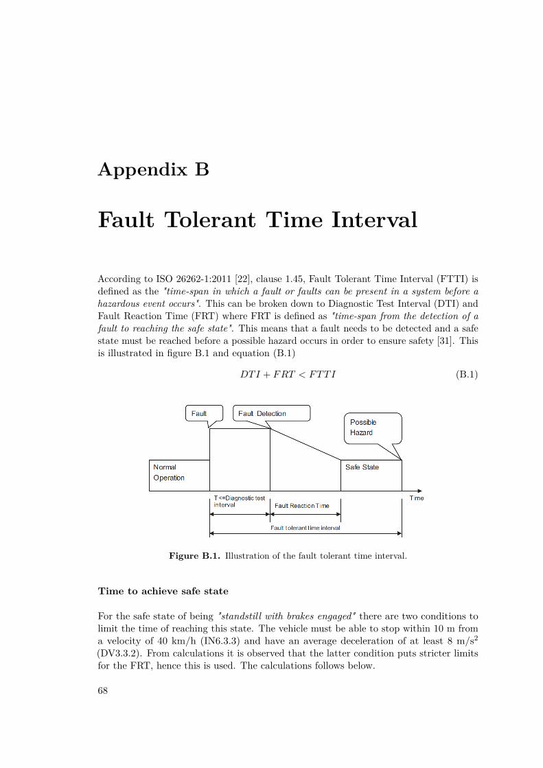
Appendix B
Fault Tolerant Time Interval
According to ISO 26262-1:2011 [22], clause 1.45, Fault Tolerant Time Interval (FTTI) isdefined as the "time-span in which a fault or faults can be present in a system before ahazardous event occurs". This can be broken down to Diagnostic Test Interval (DTI) andFault Reaction Time (FRT) where FRT is defined as "time-span from the detection of afault to reaching the safe state". This means that a fault needs to be detected and a safestate must be reached before a possible hazard occurs in order to ensure safety [31]. Thisis illustrated in figure B.1 and equation (B.1)
DTI + FRT < FTTI (B.1)
Figure B.1. Illustration of the fault tolerant time interval.
Time to achieve safe state
For the safe state of being "standstill with brakes engaged" there are two conditions tolimit the time of reaching this state. The vehicle must be able to stop within 10 m froma velocity of 40 km/h (IN6.3.3) and have an average deceleration of at least 8 m/s2
(DV3.3.2). From calculations it is observed that the latter condition puts stricter limitsfor the FRT, hence this is used. The calculations follows below.
68
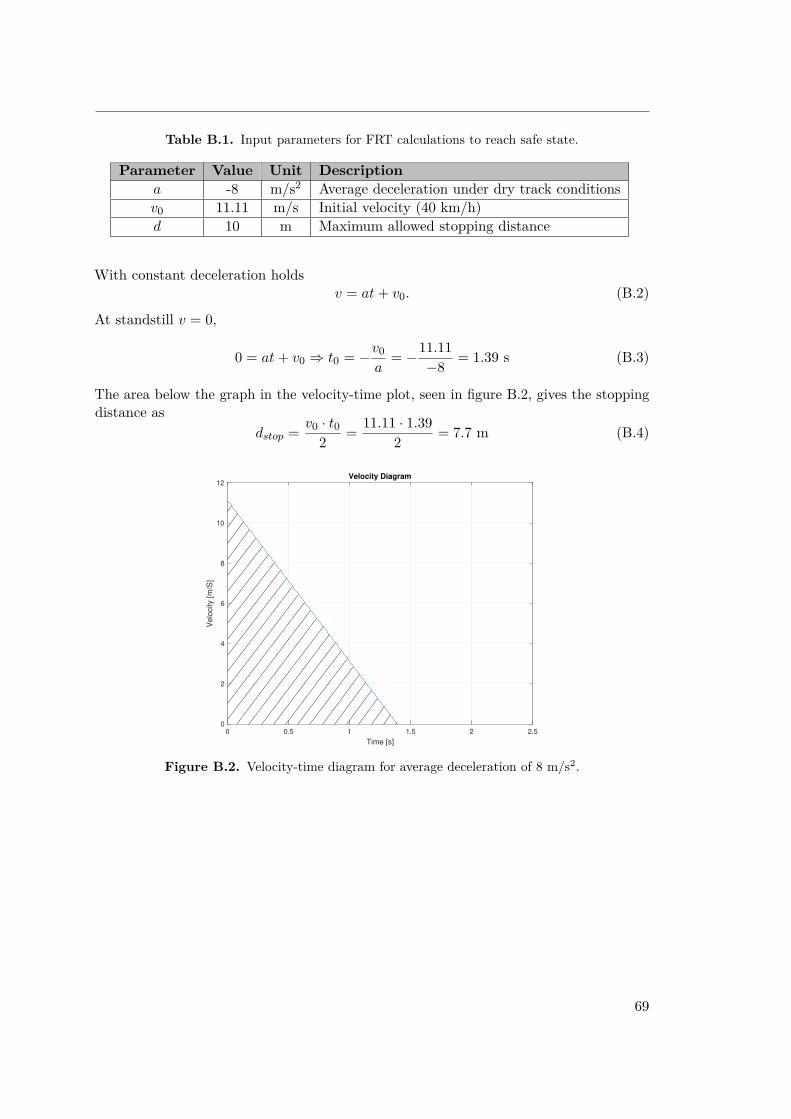
Table B.1. Input parameters for FRT calculations to reach safe state.
Parameter Value Unit Descriptiona -8 m/s2 Average deceleration under dry track conditionsv0 11.11 m/s Initial velocity (40 km/h)d 10 m Maximum allowed stopping distance
With constant deceleration holdsv = at + v0. (B.2)
At standstill v = 0,
0 = at + v0 ⇒ t0 = −v0a
= −11.11−8 = 1.39 s (B.3)
The area below the graph in the velocity-time plot, seen in figure B.2, gives the stoppingdistance as
dstop = v0 · t02 = 11.11 · 1.39
2 = 7.7 m (B.4)
0 0.5 1 1.5 2 2.5
Time [s]
0
2
4
6
8
10
12
Velo
city [m
/S]
Velocity Diagram
Figure B.2. Velocity-time diagram for average deceleration of 8 m/s2.
69
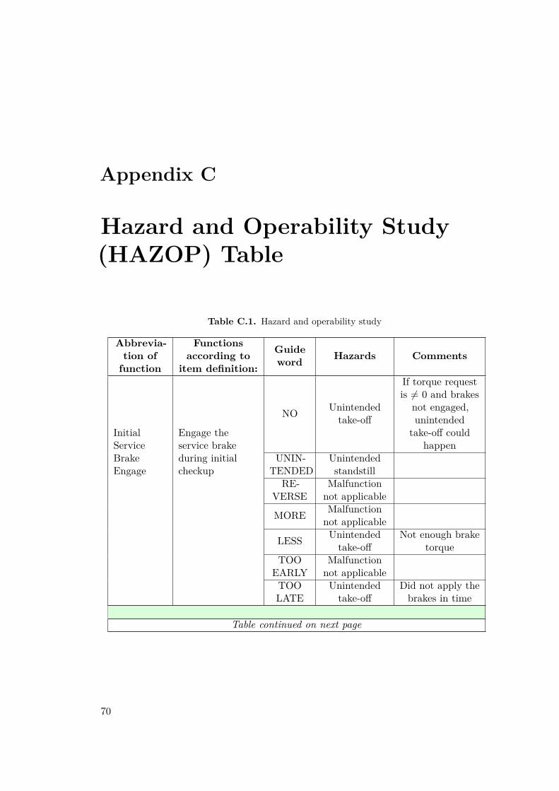
Appendix C
Hazard and Operability Study(HAZOP) Table
Table C.1. Hazard and operability study
Abbrevia-tion offunction
Functionsaccording to
item definition:
Guideword Hazards Comments
InitialServiceBrakeEngage
Engage theservice brakeduring initialcheckup
NO Unintendedtake-off
If torque requestis 6= 0 and brakes
not engaged,unintended
take-off couldhappen
UNIN-TENDED
Unintendedstandstill
RE-VERSE
Malfunctionnot applicable
MORE Malfunctionnot applicable
LESS Unintendedtake-off
Not enough braketorque
TOOEARLY
Malfunctionnot applicable
TOOLATE
Unintendedtake-off
Did not apply thebrakes in time
Table continued on next page
70

Table C.1 continued from previous pageAbbrevia-tion offunction
Functionsaccording to
item definition:
Guideword Hazards Comments
Initialcheckup
Perform an initialcheckup of thesystem and testthe brakes
NO Unintendedstandstill
Failed to reach"ready" state
UNIN-TENDED
Unintendedbraking
Checkup startedwhile driving
RE-VERSE
Malfunctionnot applicable
MORE Malfunctionnot applicable
LESS
Loss of brakefunction/unintendedbraking
Missed faultdetection
TOOEARLY
Malfunctionnot applicable
TOOLATE
Unintendedbraking
Keep Alive
Make sure thatthe EBS releasevalve is keptclosed duringnominal operation
NO Unintendedbraking
UNIN-TENDED
Loss of braketriggerfunction
Watchdog signalstill sent eventhough failure
detectionRE-
VERSEMalfunctionnot applicable
MORE Malfunctionnot applicable
LESS Malfunctionnot applicable
TOOEARLY
Unintendedstandstill
Failed to reach"ready" state ifwatchdog is senttoo early in thecheckup sequence
TOOLATE
Malfunctionnot applicable
Table continued on next page
71
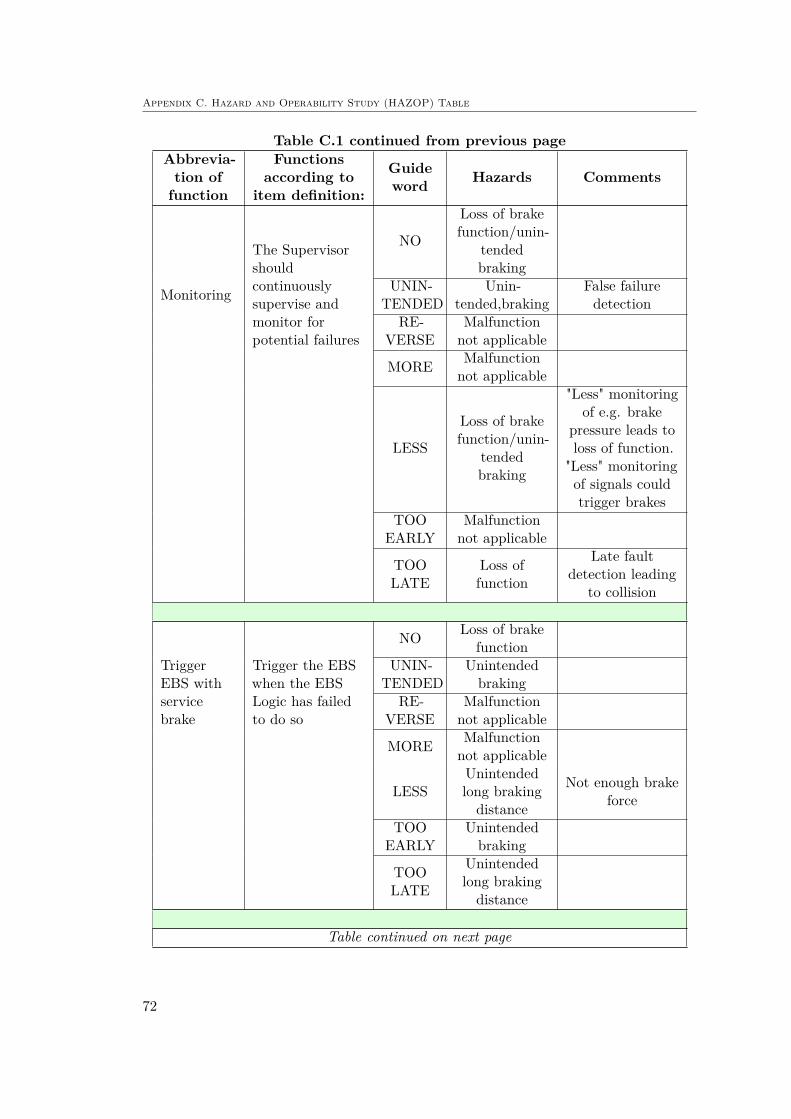
Appendix C. Hazard and Operability Study (HAZOP) Table
Table C.1 continued from previous pageAbbrevia-tion offunction
Functionsaccording to
item definition:
Guideword Hazards Comments
Monitoring
The Supervisorshouldcontinuouslysupervise andmonitor forpotential failures
NO
Loss of brakefunction/unin-
tendedbraking
UNIN-TENDED
Unin-tended,braking
False failuredetection
RE-VERSE
Malfunctionnot applicable
MORE Malfunctionnot applicable
LESS
Loss of brakefunction/unin-
tendedbraking
"Less" monitoringof e.g. brake
pressure leads toloss of function.
"Less" monitoringof signals couldtrigger brakes
TOOEARLY
Malfunctionnot applicable
TOOLATE
Loss offunction
Late faultdetection leading
to collision
TriggerEBS withservicebrake
Trigger the EBSwhen the EBSLogic has failedto do so
NO Loss of brakefunction
UNIN-TENDED
Unintendedbraking
RE-VERSE
Malfunctionnot applicable
MORE Malfunctionnot applicable
LESSUnintendedlong brakingdistance
Not enough brakeforce
TOOEARLY
Unintendedbraking
TOOLATE
Unintendedlong brakingdistance
Table continued on next page
72

Table C.1 continued from previous pageAbbrevia-tion offunction
Functionsaccording to
item definition:
Guideword Hazards Comments
BrakeHeadingControl
Ensure stabledriving condition,i.e. Nounintended yawmovement
NO Unintendedrotation
UNIN-TENDED
Loss ofsteering
RE-VERSE
Unintendedrotation/lossof steering
MORE Malfunctionnot applicable
LESS Unintendedrotation
TOOEARLY
Loss ofsteering
TOOLATE
Unintendedrotation
73

74
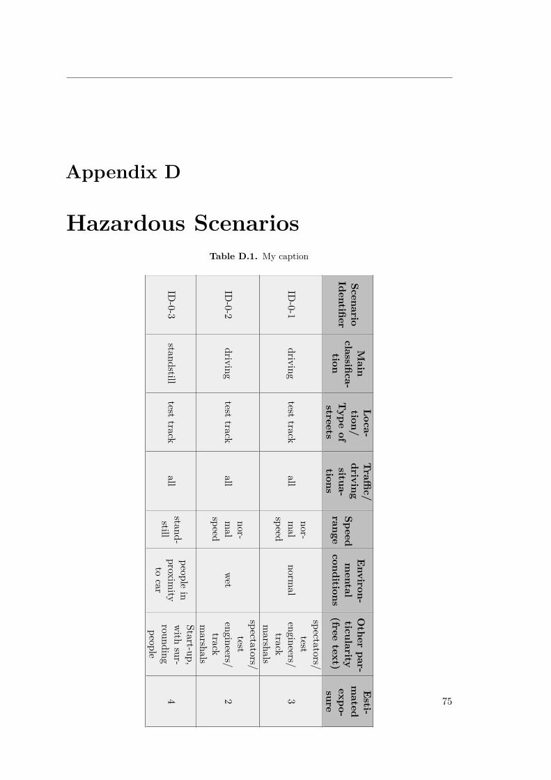
Appendix D
Hazardous ScenariosTable D.1. My caption
ScenarioIdentifier
Main
classifica-tion
Loca-tion/
Type
ofstreets
Traffi
c/drivingsitua-tions
Speedrange
Environ-mental
conditions
Other
par-ticularity(free
text)
Esti-
mated
expo-sure
ID-0-1
drivingtest
trackall
nor-mal
speednorm
al
spectators/test
engineers/track
marshals
3
ID-0-2
drivingtest
trackall
nor-mal
speedwet
spectators/test
engineers/track
marshals
2
ID-0-3
standstilltest
trackall
stand-still
peoplein
proximity
tocar
Start-up,with
sur-roundingpeople
4 75

Appendix D. Hazardous Scenarios
Table D.1 continued from previous page
H1:
unin-tendedtake-off
H2:
unin-tended
standstill
H3:
unin-tendedbraking
H4:
lossof
brakefunction
Com
-ments
forH4:
lossof
brakefunction
H5:
lossof
braketriggerfunction
H7:
unin-tendedrotation
H8:
lossof
steering
notrelevant
forthis
hazard
noaccident
iscaused
bythis
hazard
noaccident
iscaused
bythis
hazard
collisionwith
person(m
ediumdifferentialspeed)
collisionwith
person(m
ediumdifferentialspeed)
collisionwith
person(m
ediumdifferentialspeed)
collisionwith
person(m
ediumdifferentialspeed)
notrelevant
forthis
hazard
noaccident
iscaused
bythis
hazard
noaccident
iscaused
bythis
hazard
Already
coveredby
ID-0-1
Already
coveredby
ID-0-1
Already
coveredby
ID-0-1
Already
coveredby
ID-0-1
collisionwith
person(low
differentialspeed)
noaccident
iscaused
bythis
hazard
noaccident
iscaused
bythis
hazard
collisionwith
person(low
differentialspeed)
Sameconse-
quenceas
H1-ID
-0-3,different
malfunction
notrelevant
forthis
hazard
notrelevant
forthis
hazard
noaccident
iscaused
bythis
hazard
76

77

Appendix E. Hazard and Risk Analysis
Appendix E
Hazard and Risk AnalysisTable E.1. My caption
Ref.
No.
Assum
edHazard
ScenarioHazardousEvent
Severity’S’
Justificationfor
’S’
H1-ID
-0-3unintendedtake-off
standstillcollision
with
person(low
differentialspeed)2
serious,includinglife-threateninginjuries,survival
probable
H4-ID
-0-1loss
ofbrake
functiondriving
collisionwith
person(m
ediumdifferentialspeed)
3
life-threateninginjuries
(survivaluncertain)
orfatalinjuries
H4-ID
-0-3loss
ofbrake
functionstandstill
collisionwith
person(low
differentialspeed)2
serious,includinglife-threatening,injuries,survival
probable
H5-ID
-0-1
lossof
braketriggerfunction
drivingcollision
with
person(m
ediumdifferentialspeed)
3
life-threateninginjuries
(survivaluncertain)
orfatalinjuries
H7-ID
-0-1unintendedrotation
drivingcollision
with
person(m
ediumdifferentialspeed)
3
life-threateninginjuries
(survivaluncertain)
orfatalinjuries
H8-ID
-0-1loss
ofsteering
drivingcollision
with
person(m
ediumdifferentialspeed)
3
life-threateninginjuries
(survivaluncertain)
orfatalinjuries
78
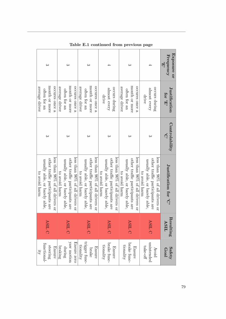
Exposure
orFrequency
’E’
Justificationfor
’E’
Controlability
’C’
Justificationfor
’C’
ResultingASIL
SafetyGoal
Table E.1 continued from previous page
4occurs
duringalm
ostevery
drive3
lessthan
90%ofalldrivers
orother
trafficparticipants
areusually
able,orbarely
able,to
avoidharm
ASIL
CAvoid
unintendedtake-off
3
occuresonce
amonth
ormore
oftenfor
anaverage
driver
3
lessthan
90%ofalldrivers
orother
trafficparticipants
areusually
able,orbarely
able,to
avoidharm
ASIL
CEnsure
brakefunc-
tionality
4occurs
duringalm
ostevery
drive3
lessthan
90%ofalldrivers
orother
trafficparticipants
areusually
able,orbarely
able,to
avoidharm
ASIL
CEnsure
brakefunc-
tionality
3
occuresonce
amonth
ormore
oftenfor
anaverage
driver
3
lessthan
90%ofalldrivers
orother
trafficparticipants
areusually
able,orbarely
able,to
avoidharm
ASIL
C
Ensurebrake
triggerfunc-
tionality
3
occuresonce
amonth
ormore
oftenfor
anaverage
driver
3
lessthan
90%ofalldrivers
orother
trafficparticipants
areusually
able,orbarely
able,to
avoidharm
ASIL
C
Ensurezero
yawmotion
duringbraking
3
occuresonce
amonth
ormore
oftenfor
anaverage
driver
3
lessthan
90%ofalldrivers
orother
trafficparticipants
areusually
able,orbarely
able,to
avoidharm
ASIL
C
Ensuresteering
functional-ity
79
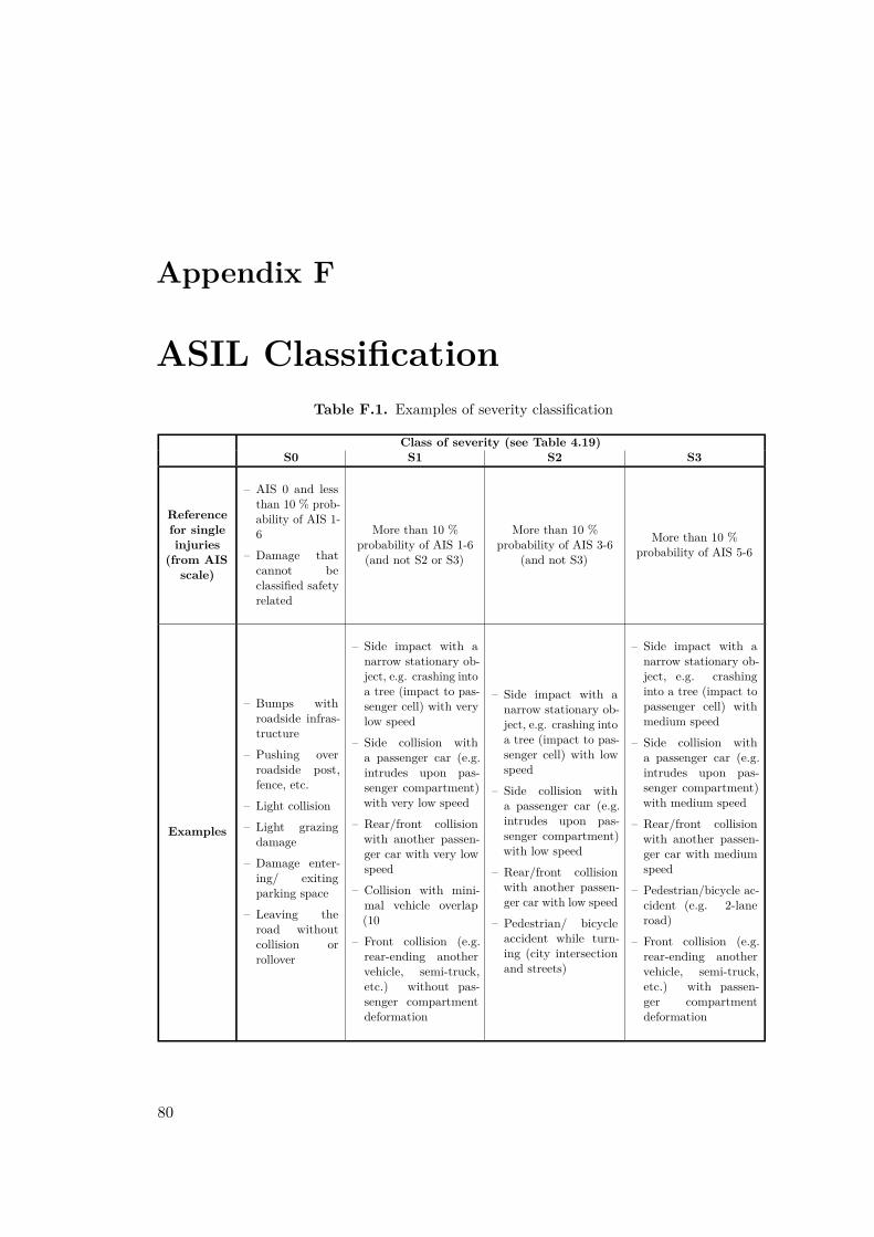
Appendix F
ASIL ClassificationTable F.1. Examples of severity classification
Class of severity (see Table 4.19)S0 S1 S2 S3
Referencefor singleinjuries
(from AISscale)
– AIS 0 and lessthan 10 % prob-ability of AIS 1-6
– Damage thatcannot beclassified safetyrelated
More than 10 %probability of AIS 1-6(and not S2 or S3)
More than 10 %probability of AIS 3-6
(and not S3)
More than 10 %probability of AIS 5-6
Examples
– Bumps withroadside infras-tructure
– Pushing overroadside post,fence, etc.
– Light collision
– Light grazingdamage
– Damage enter-ing/ exitingparking space
– Leaving theroad withoutcollision orrollover
– Side impact with anarrow stationary ob-ject, e.g. crashing intoa tree (impact to pas-senger cell) with verylow speed
– Side collision witha passenger car (e.g.intrudes upon pas-senger compartment)with very low speed
– Rear/front collisionwith another passen-ger car with very lowspeed
– Collision with mini-mal vehicle overlap(10
– Front collision (e.g.rear-ending anothervehicle, semi-truck,etc.) without pas-senger compartmentdeformation
– Side impact with anarrow stationary ob-ject, e.g. crashing intoa tree (impact to pas-senger cell) with lowspeed
– Side collision witha passenger car (e.g.intrudes upon pas-senger compartment)with low speed
– Rear/front collisionwith another passen-ger car with low speed
– Pedestrian/ bicycleaccident while turn-ing (city intersectionand streets)
– Side impact with anarrow stationary ob-ject, e.g. crashinginto a tree (impact topassenger cell) withmedium speed
– Side collision witha passenger car (e.g.intrudes upon pas-senger compartment)with medium speed
– Rear/front collisionwith another passen-ger car with mediumspeed
– Pedestrian/bicycle ac-cident (e.g. 2-laneroad)
– Front collision (e.g.rear-ending anothervehicle, semi-truck,etc.) with passen-ger compartmentdeformation
80
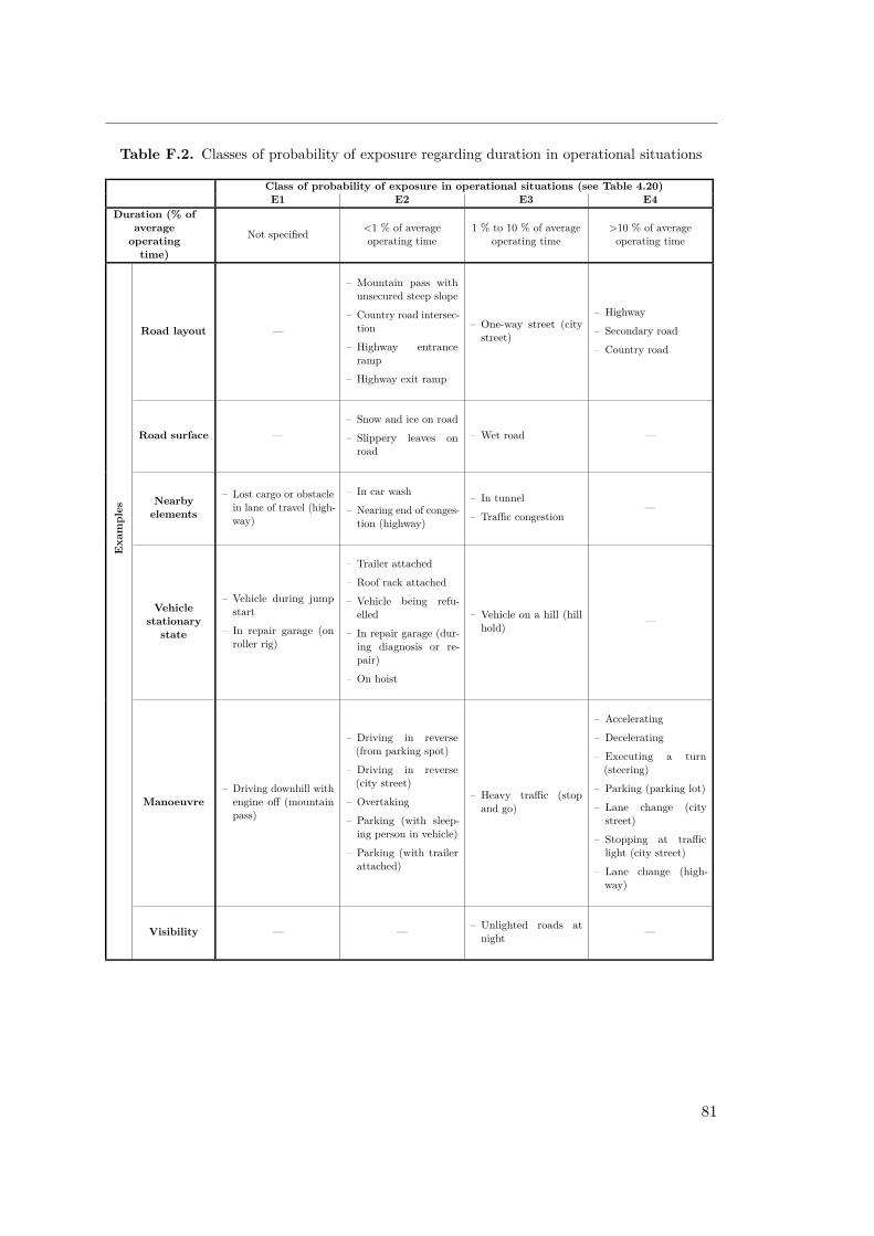
Table F.2. Classes of probability of exposure regarding duration in operational situations
Class of probability of exposure in operational situations (see Table 4.20)E1 E2 E3 E4
Duration (% ofaverageoperatingtime)
Not specified <1 % of averageoperating time
1 % to 10 % of averageoperating time
>10 % of averageoperating time
Road layout —
– Mountain pass withunsecured steep slope
– Country road intersec-tion
– Highway entranceramp
– Highway exit ramp
– One-way street (citystreet)
– Highway
– Secondary road
– Country road
Road surface —– Snow and ice on road
– Slippery leaves onroad
– Wet road —
Exa
mples
Nearbyelements
– Lost cargo or obstaclein lane of travel (high-way)
– In car wash
– Nearing end of conges-tion (highway)
– In tunnel
– Traffic congestion—
Vehiclestationary
state
– Vehicle during jumpstart
– In repair garage (onroller rig)
– Trailer attached
– Roof rack attached
– Vehicle being refu-elled
– In repair garage (dur-ing diagnosis or re-pair)
– On hoist
– Vehicle on a hill (hillhold) —
Manoeuvre– Driving downhill withengine off (mountainpass)
– Driving in reverse(from parking spot)
– Driving in reverse(city street)
– Overtaking
– Parking (with sleep-ing person in vehicle)
– Parking (with trailerattached)
– Heavy traffic (stopand go)
– Accelerating
– Decelerating
– Executing a turn(steering)
– Parking (parking lot)
– Lane change (citystreet)
– Stopping at trafficlight (city street)
– Lane change (high-way)
Visibility — — – Unlighted roads atnight —
81

Appendix F. ASIL Classification
Table F.3. Classes of probability of exposure regarding frequency in operational situations
Class of probability of exposure in operational situations (see Table 4.20)E1 E2 E3 E4
Frequency ofsituation
Occurs less often thanonce a year for the great
majority of drivers
Occurs a few times ayear for the greatmajority of drivers
Occurs once a month ormore often for anaverage driver
Occurs during almostevery drive on average
Road layout — – Mountain pass withunsecured steep slope — —
Road surface — – Snow and ice on road – Wet road —
Nearbyelements — —
– In tunnel
– In car wash
– Traffic congestion
—
Exa
mples
Vehiclestationary
state
– Stopped, requiring en-gine restart (at rail-way crossing)
– Vehicle being towed
– Vehicle during jumpstart
– Trailer attached
– Roof rack attached
– Vehicle being refu-elled
– Vehicle on a hill (hillhold)
—
Manoeuvre —– Evasive manoeuvre,
deviating from desiredpath
– Overtaking
– Starting from stand-still
– Shifting transmissiongears
– Accelerating
– Braking
– Executing a turn(steering)
– Using indicators
– Manoeuvring vehicleinto parking position
– Driving in reverse
82
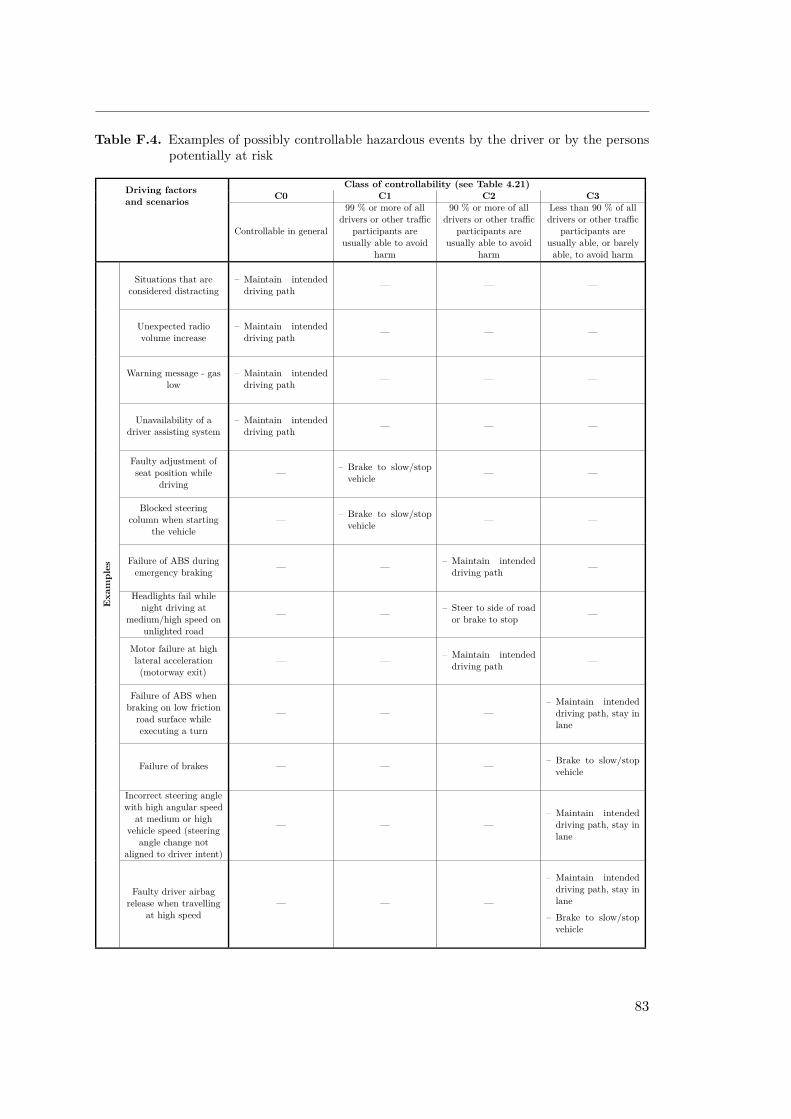
Table F.4. Examples of possibly controllable hazardous events by the driver or by the personspotentially at risk
Driving factorsand scenarios
Class of controllability (see Table 4.21)C0 C1 C2 C3
Controllable in general
99 % or more of alldrivers or other traffic
participants areusually able to avoid
harm
90 % or more of alldrivers or other traffic
participants areusually able to avoid
harm
Less than 90 % of alldrivers or other traffic
participants areusually able, or barelyable, to avoid harm
Situations that areconsidered distracting
– Maintain intendeddriving path — — —
Unexpected radiovolume increase
– Maintain intendeddriving path — — —
Warning message - gaslow
– Maintain intendeddriving path — — —
Unavailability of adriver assisting system
– Maintain intendeddriving path — — —
Faulty adjustment ofseat position while
driving— – Brake to slow/stop
vehicle — —
Blocked steeringcolumn when starting
the vehicle— – Brake to slow/stop
vehicle — —
Exa
mples
Failure of ABS duringemergency braking — — – Maintain intended
driving path —
Headlights fail whilenight driving at
medium/high speed onunlighted road
— — – Steer to side of roador brake to stop —
Motor failure at highlateral acceleration(motorway exit)
— — – Maintain intendeddriving path —
Failure of ABS whenbraking on low friction
road surface whileexecuting a turn
— — —– Maintain intended
driving path, stay inlane
Failure of brakes — — — – Brake to slow/stopvehicle
Incorrect steering anglewith high angular speed
at medium or highvehicle speed (steering
angle change notaligned to driver intent)
— — —– Maintain intended
driving path, stay inlane
Faulty driver airbagrelease when travelling
at high speed— — —
– Maintain intendeddriving path, stay inlane
– Brake to slow/stopvehicle
83

Appendix G
Technical Safety Requirements
SG1: Avoid unintended take-off
Technical Requirement: TSR1
Safety Level: ASIL CDerived From: FSR1Operation Mode: Startup
The MicroAutoBox shall continuously read:
– Torque request (Torque_request)– Service brake engage signal (Service_brake_engage)– EBS checkup done signal (EBS_checkup_done)
Technical Requirement: TSR2
Safety Level: ASIL CDerived From: FSR1Operation Mode: Startup
If EBS_checkup_done = 0, and torque value 6= 0, the service brake shall be engaged bysetting Service_brake_engage signal to high.
84

SG2: Ensure brake functionality
Technical Requirement: TSR3
Safety Level: ASIL CDerived From: FSR2Operation Mode: EBS Armed
The MicroAutoBox shall continuously read from CAN input:
– Pneumatic tank pressure (EBS_pressure)– Brake line pressure (Brake_CH1)– Service brake position request input (AS_service_brake_request)– Service brake position output (AS_service_brake_position)
Technical Requirement: TSR4
Safety Level: ASIL CDerived From: FSR3Operation Mode: Checkup
The MicroAutoBox shall continuously read from I/O input
– EBS_is_active– Shutdown_circuit– EBS_is_triggered_NOT– ASMS– Driving_state_active
and I/O output
– EBS_set_active_NOT– Brake_engage_NOT– Activate_watchdog– Service_brake_engaged– EBS_checkup_done
85
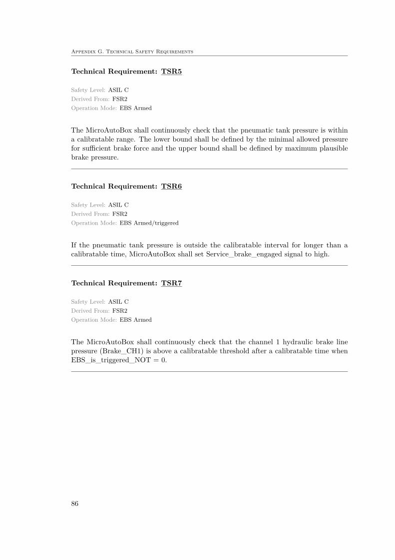
Appendix G. Technical Safety Requirements
Technical Requirement: TSR5
Safety Level: ASIL CDerived From: FSR2Operation Mode: EBS Armed
The MicroAutoBox shall continuously check that the pneumatic tank pressure is withina calibratable range. The lower bound shall be defined by the minimal allowed pressurefor sufficient brake force and the upper bound shall be defined by maximum plausiblebrake pressure.
Technical Requirement: TSR6
Safety Level: ASIL CDerived From: FSR2Operation Mode: EBS Armed/triggered
If the pneumatic tank pressure is outside the calibratable interval for longer than acalibratable time, MicroAutoBox shall set Service_brake_engaged signal to high.
Technical Requirement: TSR7
Safety Level: ASIL CDerived From: FSR2Operation Mode: EBS Armed
The MicroAutoBox shall continuously check that the channel 1 hydraulic brake linepressure (Brake_CH1) is above a calibratable threshold after a calibratable time whenEBS_is_triggered_NOT = 0.
86

Technical Requirement: TSR8
Safety Level: ASIL CDerived From: FSR2Operation Mode: EBS Armed/triggered
The MicroAutoBox shall send service brake control signal to a service brake plant modeland compare the output (position) to sensor reading of the actuators actual position.Deviations larger than a calibratable threshold for longer than a calibratable time shallresult in MicroAutoBox stopping the Watchdog toggling.
State-machine requirements
Technical Requirement: TSR9
Safety Level: ASIL CDerived From: FSR3Operation Mode: Checkup (State 2)
If state-machine outputs are
– EBS_set_active_NOT = 1– Brake_engage_NOT = 1– Activate_watchdog = 0– Service_brake_engaged = 0– EBS_checkup_done = 0
MicroAutoBox shall check that state-machine inputs are
– EBS_is_active = 0– Shutdown_circuit = 1– Brake_hydraul_check = 0– ASMS = 1– Driving_state_active = 0
87

Appendix G. Technical Safety Requirements
Technical Requirement: TSR10
Safety Level: ASIL CDerived From: FSR3Operation Mode: Checkup (State 3)
If state-machine outputs are
– EBS_set_active_NOT = 1– Brake_engage_NOT = 1– Activate_watchdog = 1– Service_brake_engaged = 0– EBS_checkup_done = 0
MicroAutoBox shall check that state-machine inputs are
– EBS_is_active = 0– Shutdown_circuit = 1– EBS_is_triggered_NOT = 0– Brake_hydraul_check = 0– ASMS = 1– Driving_state_active = 0
Technical Requirement: TSR11
Safety Level: ASIL CDerived From: FSR3Operation Mode: Checkup (State 4)
If state-machine outputs are
– EBS_set_active_NOT = 0– Brake_engage_NOT = 1– Activate_watchdog = 1– Service_brake_engaged = 0– EBS_checkup_done = 0
MicroAutoBox shall check that state-machine inputs are
– EBS_is_active = 0– Shutdown_circuit = 1– EBS_is_triggered_NOT = 1– Brake_hydraul_check = 0– ASMS = 1– Driving_state_active = 0
88

Technical Requirement: TSR12
Safety Level: ASIL CDerived From: FSR3Operation Mode: Checkup (State 5)
If state-machine outputs are
– EBS_set_active_NOT = 0– Brake_engage_NOT = 0– Activate_watchdog = 1– Service_brake_engaged = 0– EBS_checkup_done = 0
MicroAutoBox shall check that state-machine inputs are
– EBS_is_active = 1– Shutdown_circuit = 1– EBS_is_triggered_NOT = 1– Brake_hydraul_check = 0– ASMS = 1– Driving_state_active = 0
Technical Requirement: TSR13
Safety Level: ASIL CDerived From: FSR3Operation Mode: Checkup (State 6)
If state-machine outputs are
– EBS_set_active_NOT = 0– Brake_engage_NOT = 1– Activate_watchdog = 1– Service_brake_engaged = 0– EBS_checkup_done = 0
MicroAutoBox shall check that state-machine inputs are
– EBS_is_active = 1– Shutdown_circuit = 1– EBS_is_triggered_NOT = 1– Brake_hydraul_check = 1– ASMS = 1– Driving_state_active = 0
89

Appendix G. Technical Safety Requirements
Technical Requirement: TSR14
Safety Level: ASIL CDerived From: FSR3Operation Mode: Checkup (State 7)
If state-machine outputs are
– EBS_set_active_NOT = 0– Brake_engage_NOT = 1– Activate_watchdog = 1– Service_brake_engaged = 1– EBS_checkup_done = 0
MicroAutoBox shall check that state-machine inputs are
– EBS_is_active = 1– Shutdown_circuit = 1– EBS_is_triggered_NOT = 1– Brake_hydraul_check = 0– ASMS = 1– Driving_state_active = 0
Technical Requirement: TSR15
Safety Level: ASIL CDerived From: FSR3Operation Mode: Checkup (State 8)
If state-machine outputs are
– EBS_set_active_NOT = 0– Brake_engage_NOT = 1– Activate_watchdog = 1– Service_brake_engaged = 1– EBS_checkup_done = 1
MicroAutoBox shall check that state-machine inputs are
– EBS_is_active = 1– Shutdown_circuit = 1– EBS_is_triggered_NOT = 1– Brake_hydraul_check = 1– ASMS = 1– Driving_state_active = 0
90

Technical Requirement: TSR16
Safety Level: ASIL CDerived From: FSR3Operation Mode: Checkup
If state-machine outputs are not matching the inputs, MicroAutoBox shall stop state-flowprogression and set Service_brake_engaged signal to high.
91

Appendix G. Technical Safety Requirements
SG3: Ensure brake trigger functionality
Technical Requirement: TSR17
Safety Level: ASIL CDerived From: FSR4Operation Mode: EBS Armed/triggered
The MicroAutoBox shall continuously read Nvida error signal (AS_nvida_error) fromEthernet input.
Technical Requirement: TSR18
Safety Level: ASIL CDerived From: FSR4Operation Mode: EBS Armed/triggered
The MicroAutoBox shall continuously read brake line pressure signal (Brake_CH1) fromCAN input.
Technical Requirement: TSR19
Safety Level: ASIL CDerived From: FSR4Operation Mode: EBS Armed/triggered
The MicroAutoBox shall continuously read EBS_is_triggered_NOT signal from I/Oinput.
92
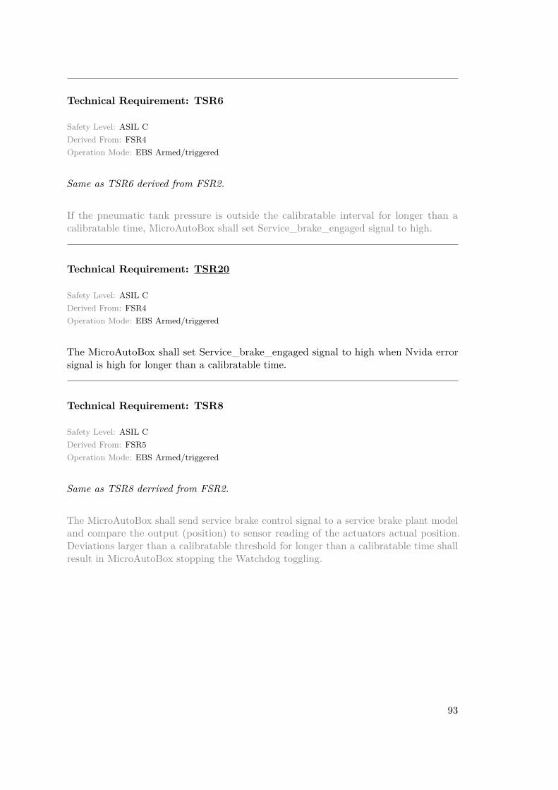
Technical Requirement: TSR6
Safety Level: ASIL CDerived From: FSR4Operation Mode: EBS Armed/triggered
Same as TSR6 derived from FSR2.
If the pneumatic tank pressure is outside the calibratable interval for longer than acalibratable time, MicroAutoBox shall set Service_brake_engaged signal to high.
Technical Requirement: TSR20
Safety Level: ASIL CDerived From: FSR4Operation Mode: EBS Armed/triggered
The MicroAutoBox shall set Service_brake_engaged signal to high when Nvida errorsignal is high for longer than a calibratable time.
Technical Requirement: TSR8
Safety Level: ASIL CDerived From: FSR5Operation Mode: EBS Armed/triggered
Same as TSR8 derrived from FSR2.
The MicroAutoBox shall send service brake control signal to a service brake plant modeland compare the output (position) to sensor reading of the actuators actual position.Deviations larger than a calibratable threshold for longer than a calibratable time shallresult in MicroAutoBox stopping the Watchdog toggling.
93

Appendix G. Technical Safety Requirements
SG4: Ensure zero yaw motion during braking
Technical Requirement: TSR21
Safety Level: ASIL CDerived From: FSR7Operation Mode: EBS triggered
The MicroAutoBox shall read the following signals from CAN:
– Current yaw movement from IMU– Current vehicle speed from wheel speed encoder– Current steering angle from steering rack potentiometer
Technical Requirement: TSR22
Safety Level: ASIL CDerived From: FSR6Operation Mode: EBS triggered
The MicroAutoBox shall read the steering angle output.
Technical Requirement: TSR23
Safety Level: ASIL CDerived From: FSR6Operation Mode: EBS triggered
The MicroAutoBox shall only allow steering torque that counteracts current IMU reading,i.e. clockwise steering shall be prohibited with clockwise vehicle rotation and vise verse.
94
Technical Requirement: TSR24
Safety Level: ASIL CDerived From: FSR7Operation Mode: EBS triggered
The MicroAutoBox shall use a look-up table based on current yaw, speed and steeringangle to define allowed steering torque.
Technical Requirement: TSR25
Safety Level: ASIL CDerived From: FSR7Operation Mode: EBS triggered
The MicroAutoBox shall compare and limit brake heading control loop steering outputwith a look-up table. The limitation shall be in terms of an interval.
95
Appendix G. Technical Safety Requirements
SG5: Ensure steering functionality
Technical Requirement: TSR26
Safety Level: ASIL CDerived From: FSR8Operation Mode: EBS triggered
The MicroAutoBox shall read EBS_is_triggered_NOT signal and enable the brakeheading control loop when signal is low.
Technical Requirement: TSR27
Safety Level: ASIL CDerived From: FSR9Operation Mode: EBS triggered
The MicroAutoBox shall read EBS_is_triggered_NOT signal and disable the brakeheading control loop when signal is high.
96
Common SG requirements
Technical Requirement: TSR-
Safety Level: ASIL CDerived From: FSR10Operation Mode: ALL modes
No technical requirements are derived from FSR10.
Technical Requirement: TSR28
Safety Level: ASIL CDerived From: FSR11Operation Mode: ALL modes
Any of the following SCS failures must result in a safe state of all connected systems[7]:
– Failures of signals transmitted by cable:
– Open circuit– Short circuit to ground
– Failures of analog sensor signals transmitted by cable:
– Short circuit to supply voltage
– Failures of sensor signals used in programmable logic:
– Implausibility due to out of range signals, e.g. mechanically impossible angleof angle sensor.
– Failures of digitally transmitted signals by wire or wireless:
– Data corruption (e.g. checked by a checksum)– Loss and delay of message (e.g. checked by transmission time outs)
97
Appendix G. Technical Safety Requirements
General Requirements
When considering a three level monitoring concept, the third level is described as acontroller monitoring level. This aims to monitor the processor with an independentmonitoring module including:
– AD monitoring– Program flow check– Standard ROM check– Cyclic RAM check– Cyclic configuration check– Cyclic ROM check– Instruction set tests– Monitoring unit response test– Standard RAM check– Q/A check– Fault reaction
These checks provide requirements of monitoring undervoltage/overvoltage of microcon-trollers, having fault counters for ADC operations and RAM checks, reset triggering dueto detection of defective ROM etc. These are all important requirements and would benecessary to implement in order to fulfill the target ASIL C level. This is however be-yond the scope of this paper and will be left as a recommendation for future improvements.
98


TRITA -SCI-GRU 2018:327
ISSN 1651-7660
www.kth.se