design and realization of distributed real-time ... and realization of distributed real-time...
TRANSCRIPT

Design and Realization of Distributed Real-Time Controllers for Mechatronic Systems
M. Deppe and M. Zanella Mechatronics Laboratory Paderborn (MLaP). University ofPaderborn. Germany
Abstract: Developing distributed embedded control systems increases the need for a consistent design approach. Our example is taken from the mechatronic design in the automotive industry and illustrates our structuring concept for a modular realization of real-time-critical controllers. In our consistent design approach we employ the structured modelling of mechatronic systems, a modular integration platform for real-time software implementation and a modular hardware platform based on FPGAs and microcontrollers.
Key words: Mechatronics, hardware-in-the-Ioop simulation. distributed real-time control, FPGA, IEEE 1394
1. INTRODUCTION
Demands on the information-processing unit in mechatronic systems are steadily increasing. This is particularly evident in the automotive industry. Ever more aggregates with mechatronic functions are integrated and linked. The result is a complex network of control units in the car. For the essential control of the car dynamics, for instance ESP (Electronic Stability Program), ABS (Anti-lock Braking System) and ASR (Anti-Spin Regulation) are linked to real-time control units. Designing and testing interlinked control units entails various problems. There is no standardized approach to the design of distributed mechatronic systems from specification to realization. Major problems are the stability and safety of distributed control algorithms and the data transfer between the different ECUs (Electronic Control Unit).
Our work is concerned with the transition, maintaining the structure, from the model representation of a mechatronic system to the implementation of the control algorithms on the prototypical application.
The original version of this chapter was revised: The copyright line was incorrect. This has beencorrected. The Erratum to this chapter is available at DOI:
© IFIP International Federation for Information Processing 2002B. Kleinjohann et al. (eds.), Design and Analysis of Distributed Embedded Systems
10.1007/978-0-387-35599-3_29

278 M Deppe and M. Zanella
The appropriate modular real-time hardware is based on common platforms, such as FPGAs (Field Programmable Gate Arrays) and microcontrollers. Results of the work presented will be illustrated by an exemplary application called the X-mobile. The X-mobile [1] is an autonomous vehicle at the scale of 1:8. The real challenge in the design of the X-mobile is due to the modularity and flexibility of the system:
Figure 1. X-mobile
The vehicle has four fully independent wheel drives, steering and active suspension. Figure 1 displays the mechanical construction. The development of the vehicle offers a chance of checking up on novel approaches to the research on mechatronic systems. Different strategies and control laws can be tested with the X-mobile, e.g., speed or/and torque drive control, drive and suspension independent or coupled. Moreover, due to its complexity, the X-mobile serves for testing real-time soft- and hardware.
2. STRUCTURED DESIGN OF MECHATRONIC SYSTEMS
For a general design approach one needs ftrst of all a structuring concept for mechatronic systems. At the lowest level of mechatronic systems, we define Mechatronic Function Modules (MFM). An MFM consists of a passive mechanical frame, sensors, actuators, and discrete-continuous information processing. The MFM concept combines the idea of information encapsulation, developed in software engineering, with that of the aggregate which is a well-established term in engineering. An MFM is assigned a certain task within a mechatronic system, usually the task to control its dynamic behavior. It disposes of physical and informational interfaces for interconnection.
The next hierarchical level is that of the Autonomous Mechatronic System (AMS). An AMS consists of a passive mechanical frame, sensors, and information processing. It has no actuators of its own but uses the
Design and Realization a/Distributed Real-Time Controllers... 279
mechanically coupled MFMs for actuation. Information processing at the AMS level, such as a human-machine interface, has the task to manage the autonomy of the system.
When more than one AMS are to be employed in a co-operating system, the necessary co-ordination has to be realized on the information-processing level. Those AMSs that operate in an co-operating system are called Crosslinked Mechatronic Systems (CMS) [2].
To design hierarchical control systems according to this structuring concept the MLaP proposes a generalization of the cascade pinciple [2] which was originally widely used for single-input single-output (SISO) systems in control engineering.
Nevertheless, the development of a mechatronic product requires interdisciplinary proceeding using an integrative software environment that makes possible co-operative design, simulation and optimization functionalities. As a result, the MLaP has developed CAMeL (ComputerAided Mechatronics Laboratory) [3]. Its modelling tool allows to build up models at the topological and mathematical levels with the help of object orientation. CAMeL offers different derivation formalisms for mechanical multi body systems, analysis, visualization, and optimization tools. The software system allows to build up models from different mechatronic domains (mechanics, hydraulics, information processing). In the development of mechatronic systems hardware-in-the-Ioop simulation (HILS) for a system test in the lab is used. In the HILS the stepwise transition from the structured modular model representation of the mechatronic system to actually mounted mechanical, hydraulic and electrical aggregates takes place. The modular-hierarchical structuring concept for mechatronic systems supports this stepwise transition from the structured model to the informationally distributed lllLS.
3. INTEGRATION PLATFORM FOR NETWORKED MECHATRONIC SYSTEMS
IPANEMA (Integration Platform for Networked Mechatronic Systems) [4] is a platform concept used for distributed real-time simulation, a basic requirement of lllLS. It allows a hierarchical and modular processing of control tasks according to the principles of the structuring concept. Although IPANEMA was mainly used for software realization of controllers [5] the structure is even suitable for our new hardware realization using FPGAs.
IP ANEMA structures each partial control task in distributed simulation in an object-oriented way. Objects of the calculator class implement the simulation kernels treating the individual partial models. They do not
280 M Deppe and M Zanella
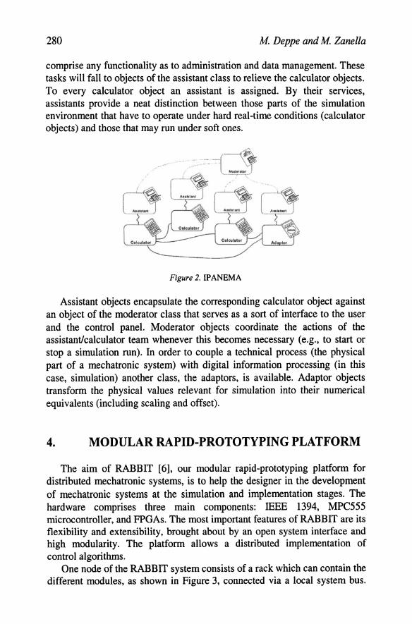
comprise any functionality as to administration and data management. These tasks will fall to objects of the assistant class to relieve the calculator objects. To every calculator object an assistant is assigned. By their services, assistants provide a neat distinction between those parts of the simulation environment that have to operate under hard real-time conditions (calculator objects) and those that may run under soft ones.
Figure 2. IPANEMA
Assistant objects encapsulate the corresponding calculator object against an object of the moderator class that serves as a sort of interface to the user and the control panel. Moderator objects coordinate the actions of the assistant/calculator team whenever this becomes necessary (e.g., to start or stop a simulation run). In order to couple a technical process (the physical part of a mechatronic system) with digital information processing (in this case, simulation) another class, the adaptors, is available. Adaptor objects transform the physical values relevant for simulation into their numerical equivalents (including scaling and offset).
4. MODULAR RAPID-PROTOTYPING PLATFORM
The aim of RABBIT [6], our modular rapid-prototyping platform for distributed mechatronic systems, is to help the designer in the development of mechatronic systems at the simulation and implementation stages. The hardware comprises three main components: IEEE 1394, MPC555 microcontroller, and FPGAs. The most important features of RABBIT are its flexibility and extensibility, brought about by an open system interface and high modularity. The platform allows a distributed implementation of control algorithms.
One node of the RABBIT system consists of a rack which can contain the different modules, as shown in Figure 3, connected via a local system bus.

Design and Realization of Distributed Real-Time Controllers ... 281
The driver module consists of power drivers, galvanic isolators for inputs and the on-board intelligence, a Xilinx Spartan-II FPGA. The FPGA is employed with control algorithms which require high sample rates. Thus the board can also work in stand-alone mode.
The main component of the DSP (Digital Signal Processing) module is a Xilinx Virtex-E FPGA. In addition to the system-bus interface, the Virtex-E also has another, local system bus interface. Via this bus, it is possible to connect I/O devices, e.g., ADCs, DACs, and encoders. These components are mounted on a piggyback board. Each DSP module can be equipped with two of these piggyback boards. The piggyback 110 configuration can be adapted to the specific demands of the application. The DSP module is designed for fast/parallel discrete controllers (e.g., current controllers and ultrasonic motors) as well as for digital filter algorithms. Sample rates of up to 100 kHz and higher are possible.
The microcontroller module of the node is provided by the Motorola PowerPC [7]. It consists of an MPC555 (52.7 MIPS, 40 MHz) with its onchip peripheral devices and an extra bus interface to transmit the memory bus signals to the local system bus. The on-chip peripherals are the serial communication (RS232), CAN interface, 32 ADC (10 bit /10 Jls) and PWM (in/out) interfaces, and 50 timers. Hence the PowerPC module can also work in stand-alone mode. Its core has a 32-bit integer ALU and a 64-bit floatingpoint unit combined in the PowerPC RISC architecture. Thus the complex control algorithms, e.g., linear / nonlinear or continuous / discrete, can be mapped to this unit of the RABBIT system.
The fourth element is the IEEE 1394 module [8]. The bus is a multimaster bus (tree topology) which configures itself at the system start or on hot-plugging of a further network device. Each module has three communication ports. IEEE 1394 allows isochronous communication at a cycle frequency of 8 kHz with a bandwidth of 400 Mbitls. This allows realtime communication of distributed control systems and high-speed field bus systems.

282 M Deppe and M Zanella
DSP modulo
Figure 3. Implemented RABBIT modules
5. PREPARING CONTROL LAWS FOR HARDWARE REALIZATION
Modem control design methods allow to create complex multi-variable control laws. The need for a transparent and consistent design process often leads to the software implementation of controllers, i.e., to the programming of microprocessor devices in a high-level language using floating-point variables. This approach is inappropriate for applications with high sample rates (fs> 20 kHz) as well as for highly modular applications consisting of cheap processing nodes. With high-level design tools, such as VHDL, and logic-synthesis CAD tools designed for large low-cost reprogrammable FPGAs, a rapid prototyping of complex modular control laws has become possible [9].
The state-space approach is a unified method for modelling and analyzing linear and time-invariant control laws. The mathematical equations are divided into two parts: a set of equations (1) relating the state variables to the input signal and a second set of equations (2) relating the state variables and the current input to the output signal. The general form of the state-space equations into which even complex control systems including observers etc. can be converted is:
x=A·x+B·u - - - (1)
(2)
Design and Realization of Distributed Real-Time Controllers... 283
The controllers are automatically laid out for a hardware realization. For this task we use our own software tool called ZSCAL. The differential equations must be transformed into difference equations and scaled from the floating-point to the fixed-point or integer ranges of numbers. The final result of the software-supported controller transformations described above is a controller specification that can be automatically converted into VHDL and C code.
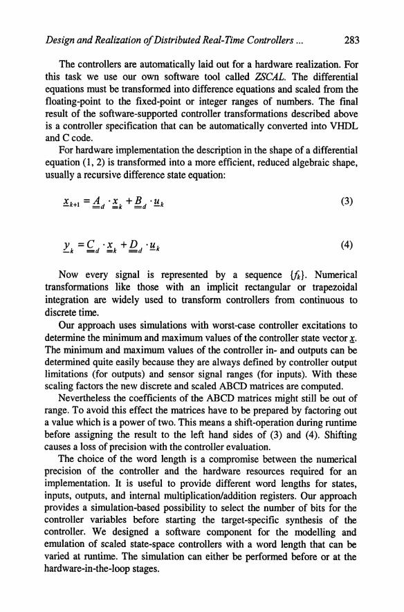
For hardware implementation the description in the shape of a differential equation (1, 2) is transformed into a more efficient, reduced algebraic shape, usually a recursive difference state equation:
x = A ·x +B ·u _k+l =d =k =d-k
y =C ·x +D ·u _k =d =k =d-k
(3)
(4)
Now every signal is represented by a sequence {fi}. Numerical transformations like those with an implicit rectangular or trapezoidal integration are widely used to transform controllers from continuous to discrete time.
Our approach uses simulations with worst-case controller excitations to determine the minimum and maximum values of the controller state vector :!. The minimum and maximum values of the controller in- and outputs can be determined quite easily because they are always defined by controller output limitations (for outputs) and sensor signal ranges (for inputs). With these scaling factors the new discrete and scaled ABCD matrices are computed.
Nevertheless the coefficients of the ABCD matrices might still be out of range. To avoid this effect the matrices have to be prepared by factoring out a value which is a power of two. This means a shift-operation during runtime before assigning the result to the left hand sides of (3) and (4). Shifting causes a loss of precision with the controller evaluation.
The choice of the word length is a compromise between the numerical precision of the controller and the hardware resources required for an implementation. It is useful to provide different word lengths for states, inputs, outputs, and internal multiplication/addition registers. Our approach provides a simulation-based possibility to select the number of bits for the controller variables before starting the target-specific synthesis of the controller. We designed a software component for the modelling and emulation of scaled state-space controllers with a word length that can be varied at runtime. The simulation can either be performed before or at the hardware-in-the-Ioop stages.

284 M Deppe and M Zanella
6. APPLICATION EXAMPLE
The controller realization of the X-mobile is based on the use of RABBIT nodes. According to the principle of modularity all four wheel suspensions are made up in essentially the same way. The steering angle of the wheel module is regulated by means of a DC motor and a gear. The steering-angle setpoint of the global steering controller located at the AMS level of the system and the measured steering angle are the inputs of the local steering controller. A P ID-TJ control law computes the controller output; the latter serves as an input for the power electronics which controls the DC motor current. This controller operates at a sample rate of 330 Hz.
The suspension of the X-mobile consists of a trailing link with a passive spring-damper unit. Additionally, in the revolute joint of the trailing link a torsion spring is set whose base displacement is regulated by means of a DC motor and a gear. To evaluate this displacement the relative torsion of the spring and the displacement of the trailing link are measured. The suspension force from the global suspension controller at the AMS level serves as a setpoint for the local PID-TJ suspension-force controller also operating at a sample rate of 330 Hz.
The four drives of the vehicle are mounted in the wheel hubs. The rotating speeds of the motors are determined by means of rotational encoders. The wheel drive (DC motor) is controlled by a PID current controller to achieve a drive torque according to the setpoint. Due to the low inductivity of the DC motors the current alteration is very fast. So the current controller operates at a sample rate of 20 kHz.
In addition to the so-called local controllers of the wheel modules at the MFM level, a global vehicle controller is needed. This controller determines the setpoints for the local controllers at a frequency of 330 Hz.
The upper part of Figure 4 displays the modular-hierarchical control structure of the X -mobile. Consideration of the different sample rates of the controllers yields the corresponding logical structure. The logical structure reflects the encapsulation of control parts by IP ANEMA calculator objects. Here it is necessary to use 5 calculators to separate the fast current controllers from the other controllers which are operating at a sample rate about 60 times lower.
To obtain the physical structure of the control application, one has to bear in mind the aspects of saving space, weight and power which are of vital importance because the X-mobile is built up at the scale of 1:8. Hence for this second version of the X-mobile we use a customized single-board solution, combining an MPC555- and a FPGA module of the RABBIT system. The power electronics is made up of 4 boards located at the wheel modules. The current controllers are transformed to fixed-point arithmetic

Design and Realization of Distributed Real-Time Controllers ... 285
and mapped to the FPGA module, every one of them encapsulated and running in parallel with timers of their own. The slower controller parts are based on floating-point arithmetics and mapped to the MPC555 module.
Control Structure
Loc,,' Local Loc:lIl Locill St.erino Slo.ri"9 Siooflrrg
Locfl1 loe.' loe.' loce' Driving Driving Drilling DrivinG
( Logical Structure
Physical Structure
Figure 4. Steps towards controller realization for the X-mobile
7. STATE OF AFFAIRS
The paper presented the realization of modular controllers. In our consistent design approach we employ a structured concept for modelling mechatronic systems, a modular integration platform for real-time implementation, and a modular hardware platform based on FPGAs and
286 M Deppe and M Zanella
microcontrollers. The example of the X -mobile served to demonstrate our modular-hierarchical realization concept for controllers.
The modular-hierarchical realization concept results in modular systems with distributed information processing. It allows to maintain the control structure from the initial modelling phase to a distributed prototyping of the system. Thus a coherent approach to the prototyping of distributed controllers is available.
REFERENCES
[1] Zanella, M.; Koch, T.; Scharfeld, F. (2001). Development and Structuring of Mechatronic Systems, Exemplified by the Modular Vehicle X-mobile. IEEFJASME International Conference on Advanced Intelligent Mechatronics (AIM 2001), Como, Italy.
[2] LUckel, 1.; Hestermeyer, T.; Liu-Henke, X. (2001). Generalization of the Cascade Principle in View ofa Structured Form ofMechatronic Systems. mEEIASME International Conference on Advanced Intelligent Mechatronics (AIM 2001), Como, Italy.
[3] Meier-Noe, U.; Hahn, M. (1999). Entwic/dung mechatronischer Systeme mit CAMeL. 3. Workshop Transmechatronik: Entwicklung und Transfer von Entwicklungssystemen der Mechatronik, Krefeld, Germany.
[4] Honekamp, U. (1998). IPANEMA - Verteilte &htzeit-Informationsverarbeitung in mechatronischen Systemen. Fortschr.-Ber. VOl, Reihe 20, Nr. 267, VOl-Verlag, DUsseldorf, Germany.
[5] Stolpe, R; Deppe, M.; Zanella, M. C. (2000). Rapid Prototyping von verteilten. hierarchischen Regelungen am Beispiel eines Fahrzeugs mit hybrid em Antriebsstrang. Zeitschrift it & ti, 42. Jg., Heft 2, pp. 54-58.
[6] Zanella, M.; Robrecht, M.; Lehmann, T.; Gielow, R; de Freitas Francisco,A.; Horst, A. (2001). RABBIT: A Modular Rapid Prototyping Platformfor Distributed Mechatronic Systems. SBCCI 2001 - XIV Symposium on Integrated Circuits and Systems Design; Brasilia, Brazil.
[7] Motorola, Inc. (1999). MPC555 Evaluation Board Quick Reference.
[8] Anderson, D. (1999). Fire Wire systems architecture: IEEE 1394a. 2nd ed., MindShare, Inc., Addison-Wesley, Reading, MA, Menlo Park, CA.
[9] Cumplido-Parra, R A.; Jones, S. R.; Goodall, R M.; Mitchell, F.; Bateman, S. (2000). High Performance Control System Processor. 3rd Workshop on System Design Automation (SDA 2000), Rathen, Germany, pp. 60-67.