design and prototyping of a low-side active clamp forward...
TRANSCRIPT

Faculty Of Engineering And Sustainable Development
DESIGN AND PROTOTYPING OF A LOW-SIDE ACTIVE CLAMP
FORWARD CONVERTER POWER SUPPLY
Comparison with an existing Fixed Frequency Resonant Power Supply
Christina Eklov
September 2014
Bachelor’s Thesis in Electronics
Bachelor’s Program in Electronics
Examiner: Daniel Ronnow
Supervisor: Efrain Zenteno


Christina Eklov Design and Prototyping of a low-side Active Clamp Forward Converter Power Supply
Preface
Many thanks to John, PSU Engineering and PSG for sharing and support.
i

Christina Eklov Design and Prototyping of a low-side Active Clamp Forward Converter Power Supply
ii

Christina Eklov Design and Prototyping of a low-side Active Clamp Forward Converter Power Supply
Abstract
This thesis details the design, build and commissioning of an active clamp forward
converter with synchronous rectification and comparison to an existing fixed fre-
quency resonant switching converter power supply. The points of comparison are:
noise and ripple, power efficiency, number of components, size of components and
cost. The goal is to increase the efficiency by 10% and reduce the cost and compo-
nent count by 33% as compared to the existing design. A partial implementation of
the new design was completed in the project timeframe and a provisional comparison
showed a promising efficiency and reduced component count for comparable cost.
Design improvements are proposed and follow up work is discussed to prototype a
complete unit and confirm these results.
iii

Christina Eklov Design and Prototyping of a low-side Active Clamp Forward Converter Power Supply
iv

Table of contents
Preface . . . . . . . . . . . . . . . . . . . . . . . . . . . . . . . . . . . . . . . . . . i
Abstract . . . . . . . . . . . . . . . . . . . . . . . . . . . . . . . . . . . . . . . . . iii
Table of contents . . . . . . . . . . . . . . . . . . . . . . . . . . . . . . . . . . . v
1 Introduction . . . . . . . . . . . . . . . . . . . . . . . . . . . . . . . . . . . . 1
2 Theory . . . . . . . . . . . . . . . . . . . . . . . . . . . . . . . . . . . . . . . . 2
2.1 Power Supply Basics . . . . . . . . . . . . . . . . . . . . . . . . . . . . . . 2
2.1.1 Design specifications and efficiency . . . . . . . . . . . . . . . . . . 6
2.2 Transformer Design Basics . . . . . . . . . . . . . . . . . . . . . . . . . . . 7
3 Process and result . . . . . . . . . . . . . . . . . . . . . . . . . . . . . . . . . 8
3.1 Active clamp PWM controller . . . . . . . . . . . . . . . . . . . . . . . . . 8
3.1.1 LM5027A functional overview . . . . . . . . . . . . . . . . . . . . . 8
3.2 Main Design . . . . . . . . . . . . . . . . . . . . . . . . . . . . . . . . . . . 9
3.2.1 Feedback loop . . . . . . . . . . . . . . . . . . . . . . . . . . . . . . 17
3.3 Transformer design . . . . . . . . . . . . . . . . . . . . . . . . . . . . . . . 20
3.4 PCB design . . . . . . . . . . . . . . . . . . . . . . . . . . . . . . . . . . . 21
3.5 Commissioning . . . . . . . . . . . . . . . . . . . . . . . . . . . . . . . . . 22
3.6 Results . . . . . . . . . . . . . . . . . . . . . . . . . . . . . . . . . . . . . . 27
4 Discussion . . . . . . . . . . . . . . . . . . . . . . . . . . . . . . . . . . . . . . 28
5 Conclusion . . . . . . . . . . . . . . . . . . . . . . . . . . . . . . . . . . . . . 29
References . . . . . . . . . . . . . . . . . . . . . . . . . . . . . . . . . . . . . . . . 30
Appendix A . . . . . . . . . . . . . . . . . . . . . . . . . . . . . . . . . . . . . . . A1
Appendix B . . . . . . . . . . . . . . . . . . . . . . . . . . . . . . . . . . . . . . . B1
v

Christina Eklov Design and Prototyping of a low-side Active Clamp Forward Converter Power Supply
vi

Christina Eklov Design and Prototyping of a low-side Active Clamp Forward Converter Power Supply
1 Introduction
Switch mode power supplies are a major component in modern electronic equipment
and must often be designed to meet conflicting criteria, requiring compromises to be
made in the design. Therefore engineers are continuously investigating new topologies
of switch mode power supplies that enable them to be designed with fewer compro-
mises between the design criteria, while still producing power supplies that are robust
and more efficient. One such topology is the active clamp forward converter with syn-
chronous rectification. Provided that the theory is sound this topology should provide
increased efficiency with a decrease in the number of components required compared
to existing fixed frequency converters. The attraction with the active clamp forward
converter is that it implements zero voltage switching on the primary side, the same as
the existing power supply but with synchronous rectification on the secondary side. The
synchronous rectification helps to minimize the conduction losses in the power supply. A
choice of a low side switching configuration was made due to the high voltages involved
and a floating high side switching MOSFET was considered unwise. The difficulty with
the low side active clamp approach in this case is the high voltage aspect, as the existing
power supply’s boost voltage is 320 VDC and this will have a negative impact on the
size of all components, especially the semiconductors on the primary side.
1

Christina Eklov Design and Prototyping of a low-side Active Clamp Forward Converter Power Supply
2 Theory
2.1 Power Supply Basics
A power supply is basically a converter and all converters are based on the idea of having
an input power, converting this in some way and getting an output power. There is a
multitude of different types of converters; DC-DC converters, AC-AC cycloconverters,
DC-AC inverters but the subject of this thesis is a variety of the AC-DC converter, that
is, taking a voltage of a sinusoidal waveform at a certain frequency as input and getting
a DC voltage as output.
Within the AC-DC converter family there are two major types of power supply tech-
nologies: linear regulators and pulse width modulated switching power supplies, the
latter more commonly named switch mode power supplies. Within this group of power
supplies there is again a multitude of different ways to accomplish the conversion but
if the focus is narrowed to isolated switch mode power supplies it can be see that that
group shares a few basic building blocks, as shown in Fig. 1.
Fig. 1. Basic isolated switch mode power supply building blocks.
Going forward it has been assumed that the filter, rectifier and the boost stage have
already been designed and as these circuits are not the focus of this thesis, their design
is not covered.
2

Christina Eklov Design and Prototyping of a low-side Active Clamp Forward Converter Power Supply
Moving into specifics let’s look at the building blocks of the fixed frequency resonant
converter power supply as seen in Fig. 2 where there are two converters, a transformer,
a regulator and a feedback loop.
Fig. 2. Fixed frequency resonant converter building blocks.
The boost converter takes the rectified AC voltage and turns it into a DC voltage and the
push-pull converter switches that DC voltage through the transformer to get a stepped
down voltage on the secondary side. The Buck regulator provides output voltage regu-
lation and current limiting.
The active clamp forward converter, which is an adaptation of the forward converter,
takes the place of the old push-pull converter and the synchronous rectification stage
replaces the synchronous Buck regulation, the resulting configuration can be seen in
Fig. 3. The assumption in further theory is that the active clamp converter has a DC
input voltage.
Fig. 3. Building blocks of the Active Clamp Forward Converter.
3

Christina Eklov Design and Prototyping of a low-side Active Clamp Forward Converter Power Supply
A generic low-side active clamp converter with free wheeling synchronous rectification
can be seen in Fig. 4, where L leakage and L mag is the leakage inductance and magne-
tizing inductance of the transformer respectively and C par is the parasitic capacitance
of the main MOSFET, TR main. In the design proposed there is one free wheeling
MOSFET and one driven MOSFET but the theory remains the same. A more in depth
analysis of the currents, voltages and timings involved in this design can be found in [1]
but the general idea is shown in Fig. 5 and the timings are described below.
Fig. 4. Generic low-side active clamp with free wheeling synchronous rectification configuration.
Fig. 5. Primary side switching voltage and drive signals of the low-side active clamp converter.
4

Christina Eklov Design and Prototyping of a low-side Active Clamp Forward Converter Power Supply
t0 At time t0 the main voltage VIN is on and the drive signals off, making the switching
voltage rise to VIN.
t1 At t1 the main drive signal turns on, turning on the TR main MOSFET and shorting
the switching voltage to 0V. The current is now flowing clockwise in the primary
side, through the MOSFET.
t2 At t2 the main drive signal turns off, turning off the TR main MOSFET, but the
current continues to flow in the same direction now charging C par up till the
voltage has reached VIN level and the capacitance is fully charged. The body
diode of the clamp MOSFET, TR clamp, then starts conducting and the current
starts charging the clamp capacitor C clamp until the switching voltage has reached
VIN/(1−D), where D is the duty ratio of the TR main drive signal.
t3 At t3 the clamp drive signal turns on and so turns on TR clamp. This means the
switching voltage stops being clamped to VIN/(1 − D) and magnetizing energy
starts to charge the clamp capacitor. Half way into the on time of the clamp MOS-
FET the magnetizing current will reverse direction and start going anti-clockwise
as the inductance and capacitance have fully charged and now starts to discharge.
t4 At t4 the clamp drive signal turns back off and with it the clamp MOSFET TR clamp.
This means the switching voltage again initially is clamped to VIN/(1 − D) and
the current starts flowing through C par, discharging the leakage and magnetizing
inductances. When these are fully discharged the switching voltage is equal to 0V.
t5 At t5 the main MOSFET TR main turns on again and the cycle starts over from
time t1.
5

Christina Eklov Design and Prototyping of a low-side Active Clamp Forward Converter Power Supply
2.1.1 Design specifications and efficiency
The existing power supply has an input voltage of 115 VAC with a frequency range
between 360 Hz and 800 Hz. The turn-on voltage is 94 VAC ± 2 VAC and the turn-off
voltage is 86 VAC ± 2 VAC. The turn-off voltage of 86 VAC and the nominal input
voltage of 115 VAC translates to a boost voltage turn-off and nominal voltage of 160
VDC and 320 VDC respectively.
The internal clock frequency is set to 200 kHz. The internal frequency sets the speed at
which the main control chip runs at.
The output voltage of the existing power supply is +12 VDC with regulation ± 2%,
ripple (@ 1 MHz) and noise (@200 MHz) of 2% peak to peak at 8.0 A, a current limit
of 10.4 A, and load conditions as stated in Table 1.
Table 1. Operational Load Conditions
Operational Load Conditions Requirement
Minimum Load +12 V - 0.75 A
Idle Load +12 V - 1.50 A
Nominal Load +12 V - 6.30 A
Maximum Load +1 2V - 8.00 A
The efficiency is rated to ≥80%. Efficiency is calculated as the quotient of the output
voltage multiplied by the output current divided by the input voltage multiplied by the
input current, see Eq. (1).
Efficiency =Vout · IoutVin · Iin
(1)
Voltages are measured as close to the power supply input and output connections as
possible and current is measured as a voltage drop over a sense resistor with a known
value in series with the input or output return see Fig. 6.
6

Christina Eklov Design and Prototyping of a low-side Active Clamp Forward Converter Power Supply
The efficiency of the active clamp forward converter is measured in the same way al-
though here we have 320 VDC on the input.
Fig. 6. Efficiency measurement of existing power supply.
2.2 Transformer Design Basics
The theory of magnetics are extensive and well beyond the scope of this thesis.
The purpose of the transformer in a switch mode power supply is for isolation between
the primary and secondary but also to step up or down the voltage from primary to
secondary. In an ideal transformer the input power equals the output power, this is not
the case in reality though. In a real transformer there are a number of loss factors but
the major, and often the only, two that are taken into account are copper losses and
core losses. Copper losses are losses due to heat buildup in the transformer winding as
a result of wire resistance and this changes with the load condition. At light load the
loss is less and at higher load the losses are greater, the losses can be calculated as
Pcopper = I2Rwinding (2)
where Pcopper is copper loss in watts, I is the total current going through the
transformer in ampere and Rwinding is the wire resistance of both primary and
secondary windings of the transformer in ohms.
Core losses, which are constant, are losses mainly due to a combination of hysteresis
losses, losses due to magnetizing inductance and Eddy current losses, losses due to
induced current as a result of magnetic core flux variations.
In designing a transformer for a specific application the copper losses and core losses
must be balanced to minimize the overall power loss. However this does not mean that
they as a rule should be the same. Pcopper 6= Pcore for most switch mode power supplies.
7

Christina Eklov Design and Prototyping of a low-side Active Clamp Forward Converter Power Supply
3 Process and result
3.1 Active clamp PWM controller
The design of the single ended active clamp forward converter was based around the
LM5027A chip which is a voltage mode active clamp controller. The decision in using
this particular chip was that it was financially viable and also restricted in its maximum
duty cycle to 70%. The LM5027A is the chip that gives the main MOSFET, clamp
MOSFET and the synchronous MOSFET their drive signals but it also sports features
like; overvoltage protection, undervoltage lockout and soft start.
3.1.1 LM5027A functional overview
The LM5027A is a Voltage Mode Active Clamp Controller and main control component
of the primary side circuit. The LM5027A is an integrated circuit that supplies the
switching signals, and their duty cycle to the clamp (OUTB), the main (OUTA) and the
synchronous rectification (OUTSR) MOSFETs.
When powering up the overall electrical circuit the LM5027A output signals are disabled
until the voltage on the VCC pin reaches 9.5 V, the internal voltage reference reaches
5 V, the UVLO pin voltage is greater than 2 V, and the OTP pin voltage is greater
than 1.25 V. The LM50247A is now in the start-up mode and initializes a soft-start
sequence. As a first step in the soft-start sequence the soft-start pins external capacitor
is charged by an internal current source raising the voltage on the soft-start pin. As
this pin voltage reaches 1.0 V the OUTA (main primary side) and OUTB (primary side
clamp) drive signals start switching with an increasing duty cycle. The soft-start pin
voltage continues to rise towards it final level of 5 V and as it reaches 4 V the external
capacitor on the soft-start synchronous rectification (SSSR) pin starts charging by an
internal current source. The voltage on the SSSR pin starts increasing and as it reaches
2.5 V the OUTSR (secondary side synchronous rectification) drive signal is enabled and
starts switching with increasing duty cycle. When the soft-start and SSSR pin voltages
both has reached 5 V the soft-start sequence is over and normal operation begins.
Under normal operation the duty cycle of the OUTA, OUTB and OUTSR switching
drive signals are controlled by the input on the COMP pin, where the drive signals
have maximum duty cycle at zero input current and zero duty cycle at 1 mA. The
switching drive signals will then stay enabled, with variable duty cycle, unless one of the
8

Christina Eklov Design and Prototyping of a low-side Active Clamp Forward Converter Power Supply
following events occurs; the VCC pin voltage falls below 6.0 V, the line undervoltage
lockout (UVLO) pin voltage falls below 2.0 V, the over-temperature protection (OTP)
pin voltage falls below 1.25 V or the feed-forward modulation ramp (RAMP) pin voltage
exceeds 2.5 V.
3.2 Main Design
Starting the main design and looking at the LM5027A, a connection diagram taken from
the LM5027A datasheet can be seen in Fig. 7 and the setup of the chip and surrounding
components will be described here pin by pin.
Fig. 7. LM5027A Pinout. [2]
Pin 1 - VIN
This is the input to the startup regulator and the range is 13 VDC to 90 VDC. As the
design has an input of up to 320 VDC and the LM5027A has the ability to be driven
solely with the VCC powered, this pin was left unconnected.
Pin 2 - RAMP
The RAMP, or feed-forward modulation ramp, gives the LM5027A information about
changes in the input voltage before they appear on the output so that the feedback loop,
looking at the output voltage, only needs to make small corrections. The ramp ampli-
tude, which increases with decreasing input voltage amplitude, is set by resistor RFF
and capacitor CFF connected to the Ramp pin on the IC. The maximum duty cycle,
Dmax was set to 23 and as the switching frequency, fsw = 200kHz and the value of the
lowline voltage, VIN low = 160V , is known from the specifications of the existing power
9

Christina Eklov Design and Prototyping of a low-side Active Clamp Forward Converter Power Supply
supply, the values of RFF and CFF can be calculated using the following equation where
Vref = 2.5 V and noting that the value of CFF should not be below 100 pF nor above
1000 pF, see [2][3].
Note: Initially the RFF value was misread from the calculations and three 47 kΩ resis-
tors were erroneously used in the schematic, see Appendix A, the value of the resistors
were changed as a part of the commissioning phase, subsection 3.5, to the correct value
of 470 kΩ.
ton = Dmax ·1
fc=
2
3· 1
200000(3)
RFF · CFF =VIN · tonVref
(4)
RFF · CFF =160 · 23 ·
1200000
2.5(5)
RFF · CFF =2
9375(6)
The RFF value is chosen with E24 values in mind and also that it is a high voltage
connection so three 1206 package resistors in series were needed. As always the power
loss needs to be taken into account and so using the highest value possible without
making CFF too small.
RFF = 470 kΩ · 3 = 1.41 MΩ (7)
CFF =2
9375
1.41 · 106(8)
CFF ≈ 151.3 pF (9)
Using E24 values adjusts CFF to 150 pF and the maximum power loss in the RFF chain
is then calculated as seen in Eq. (10).
Ploss =3202
470 kΩ · 3≈ 73 mW (10)
10

Christina Eklov Design and Prototyping of a low-side Active Clamp Forward Converter Power Supply
Pin 3 - TIME3
The external resistance on this pin sets the delay between the time when the main MOS-
FET is turned off and the clamp MOSFET is turned on. Using the appropriate graph
in [2], initially this was set to approximately 75 ns by a 24 kΩ 0603 package resistor but
this was changed to a 62 kΩ resistor in the build stage giving a delay of approximately
200 ns.
Pin 4 - TIME2
The external resistance on this pin sets the delay between the time when the main MOS-
FET is turned off and the synchronous MOSFET is turned on. Using the appropriate
graph in [2], initially this was set to approximately 100 ns by a 33 kΩ 0603 package
resistor but this was changed to a 56 kΩ resistor in the build stage giving a delay of
approximately 200 ns.
Pin 5 - TIME1
The external resistance on this pin sets the delay between the time when the clamp
MOSFET is turned off and the main MOSFET is turned on, it also sets the maximum
duty cycle calculated by Eq. (11) where 0.72 is the internally restricted 72% maximum
duty cycle for the LM5027A. Using the appropriate graph in [2] the delay T1 was set to
approximately 270 ns by a 56 kΩ and a 27 kΩ 0603 package resistor in series giving a
maximum duty cycle of 66%.
Max Duty Cycle =0.72 · 1
fsw− T1
1fsw
(11)
Pin 6 - AGND
Analog ground. This is connected straight to power ground PGND.
Pin 7 - RT
RT or oscillator frequency control and sync clock input sets the internal oscillator. A
resistor between the pin and ground sets the fundamental frequency and though this
resistor is essential, an external pulse can be used to sync the LM5027A to an external
source providing that that pulse frequency is at least 10% higher than the frequency set
by the resistor. Initially this pin was connected to an arbitrary function generator via
a 100 pF capacitor running at a frequency of 200 kHz and the fundamental frequency
was set to 150 kHz by one 56 kΩ and one 24 kΩ resistor. This was changed during the
11

Christina Eklov Design and Prototyping of a low-side Active Clamp Forward Converter Power Supply
commissioning phase and the frequency fsw was set to 200 kHz by a resistor at a value
calculated by Eq. (12), found in [2].
RRT =1
fsw · 8.3567 · 10−11(12)
Pin 8 - COMP
This is the input pin to the pulse width modulator inside the chip and here is where the
result from the secondary side feed-back loop is fed. To get an isolated secondary side
the feedback circuit is connected to an optocoupler and the other end of the optocoupler
is connected to the COMP pin, as the current through the optocoupler to the pin goes
from zero up to 1 mA the PWM duty cycle goes from maximum to zero. As the drive
signals are based on the PWM they will also change with the increasing or decreasing
current from the feed back loop. This means that the drive signal duty cycle can adjust
to load changes or input voltage changes.
Pin 9 - REF
A 5 VDC output, this is decoupled with a 100 nF capacitor to ground, initially this
capacitor was overlooked but was added during the commissioning phase. The optocou-
pler mentioned in the previous section is powered from this pin.
Pin 10 - OUTB
The output on this pin is the clamped P-channel MOSFET drive signal. It was decided
to put in an external buffer for this signal, partly to suppress any noise on the signal
due to the switching of the MOSFET but also as it was unsure if the LM5027A could
source enough current to drive the MOSFET.
Pin 11 - OUTA
The output on this pin is the main N-channel MOSFET drive signal. As for the OUTB
pin it was decided to put in an external buffer for this signal, partly to suppress any
noise on the signal due to the switching of the MOSFET but also as it was unsure if the
LM5027A could source enough current to drive the MOSFET.
Pin 12 - OUTSR
The output on this pin is the secondary side synchronous N-channel MOSFET drive
signal.
12

Christina Eklov Design and Prototyping of a low-side Active Clamp Forward Converter Power Supply
Pin 13 - PGND
Power ground. Connected to analog ground AGND
Pin 14 - VCC
As VIN is not connected, this pin serves as the input power pin for driving the chip
connected via a RC-network to the 12 V rail VAUXP. The RC-network consists of a
10 Ω resistor and a 100 nF capacitor.
Pin 15 - CS
Current sense input. An overcurrent state occurs when the voltage on this pin reaches
500 mV. To isolate the current for measurement a 100:1 current transformer was used.
The value of the sense resistor was dependent on the current amplitude the overcurrent
state should trip at and this would be just over the sum of the max load current, the
magnetizing current, the current through the inductance on the secondary side and stray
leakage currents. The max load current was set to 10.4 A, the same as the existing power
supply and the secondary side inductance current was calculated in Eq. (15).
tDmax = Dmax ·1
fsw(13)
tDmax =2
3· 1
200 kHz(14)
ILcurr =VOUT · tDmax
LL2(15)
ILcurr =12V ·
(23 ·
1200 kHz
)36 µH
(16)
As these are both secondary side currents they have to be scaled twice, from secondary
to primary side and then again over the current transformer, resulting in
12.95 mA at the current sense pin. To account for the magnetizing current and stray
leakage currents the overcurrent state was set to 20 mA. This in turn sets the sense
resistor value to 25 Ω but a 24 Ω resistor was chosen as it was easily available. An
RC-network was also connected to the CS pin, this to stop the LM5027A going into over
current due to spikes, transients or noise. A time constant of 50 ns was chosen and the
resistor chosen to 100 Ω making the theoretical capacitance 500 pF but 470 pF was used
as it was the closest E24 value easily available. A diode was also put in in series with
13

Christina Eklov Design and Prototyping of a low-side Active Clamp Forward Converter Power Supply
the decoupling resistor to suppress negative voltage on the CS pin.
Note: Initially the capacitance was miscalculated to 75 pF and the secondary side con-
nections on the transformer were switched, both errors were discovered and corrected
during the commissioning phase.
Pin 16 - SS
Soft start pin. When this pin reaches between 1 V to 3 V the main drive signal, OUTA,
and the clamp drive signal, OUTB, are enabled and OUTA then increases with the volt-
age on the SS pin. This pin has an internal current source of 22 µA, ISS , that charges
the external capacitor, CSS , where the value of the capacitor sets the time between the
voltage being applied to VCC and the SS pin reaching 3 V. An initial value of 5 ms, tSS ,
was decided for the soft start and the value of the capacitor can be seen calculated in
Eq. (17). This was miscalculated to 33 nF but as the time difference with this erroneous
value only was 100 µs the 33 nF value was used.
CSS =ISS · 5 ms
3 V(17)
CSS ≈ 36 nF (18)
Pin 17 - RES
Restart timer, or current limit restart timer pin. If an overcurrent condition is detected
on the CS pin an internal 22 µA current source on the RES pin is enabled and the
external capacitor CRES on the RES pin charges up. The value of the CRES capacitor
decides how many times an overcurrent condition can take place, in a row, before the
RES pin voltage reaches 1 V and a hiccup mode ensues [2]. If no overcurrent condition
occurs a 5 µA current sink discharges the CRES capacitor and the RES pin gets tied to
ground. As this feature needed to be adjusted to suit the application an initial value of
47 nF, suggested by [3] was chosen.
Pin 18 - SSSR
Soft start for synchronous rectifier output. This is a part of the soft start for the power
supply. As the voltage on the soft start pin reaches 4 V the internal 25 µA current source
is enabled and starts charging the external CSSSR capacitor. When the voltage on the
SSSR pin reaches approximately 2.5 V the synchronous drive signal, OUTSR, is enabled
and increases with the rising voltage on the SSSR pin. According to the specifications
14

Christina Eklov Design and Prototyping of a low-side Active Clamp Forward Converter Power Supply
of the fixed frequency resonant power supply the main output of the unit should have a
rise time between 5 ms and 20 ms. This rise time is set with the value of the capacitor
externally connected to the SSSR pin and the value is calculated with Eq. (19), giving
a rise time to 12.5 ms, tSSSR = 12.5 ms.
CSSSR =ISSSR · tSSSR
VSSSR(19)
CSSSR =25 · 106 · 12.5 · 10−3
2(20)
CSSSR = 156 nF (21)
Using E24 values adjusts the capacitance to CSSSR ≈ 150 nF and the adjusted rise time
becomes 12 ms.
Pin 19 - OTP
Over temperature protection pin. This pin was not needed as the existing power supply
already has an over temperature circuit and was pulled up to the REF pin via a 10 kΩ
resistor as to not induce an erroneous over-temperature condition.
Pin 20 - UVLO
Line undervoltage lockout. An external voltage divider sets the limits on turn-off and
turn-on input voltage where the total resistance is calculated according to Eq. (22) and
the calculation for R2 in the voltage divider can be seen in Eq. (23) [2]. An extra resistor,
R3, is put in line with the UVLO pin to facilitate adjustment and the calculation for
this resistor can be seen in Eq. (28). The UVLO has an internal 20 µA current sink,
Ihys = 20 µA, that provides hysteresis as the voltage on the pin exceeds 2 V.
As the specifications for the existing power supply state that the unit should turn off
when the boost voltage falls below 160 V, VPWR = 160 V, this must be the 2 V equivalent,
Vthr = 2.0 V, as the internal comparator turns the unit off when the voltage on the UVLO
pin goes below 2 V. As the turn on boost voltage as per specifications should be 250 V
the equivalent comparator voltage is 3.125 V and the hysteresis voltage is then
3.125 V - 2 V = 1.125 V, VHY S = 1.125 V.
Rtot =VHY S
Ihys(22)
15

Christina Eklov Design and Prototyping of a low-side Active Clamp Forward Converter Power Supply
R2 =Vthr ·R1
VPWR − Vthr − Ihys ·R1(23)
Rtot =1.125
20 · 10−6(24)
Rtot = 56250 Ω (25)
Rtot ≈ 56 kΩ (26)
Rtot = R3 +1
1R1
+ 1R2
(27)
Deciding on a high value for R1 as to limit power loss and the fact that three 1206
packaged resistors were needed due to the high voltage, R1 = 3 MΩ (1 MΩ · 3) was
chosen. The value for R2 was decided to be 38 kΩ.
R3 = Rtot −1
1R1
+ 1R2
≈ 18475 Ω (28)
Adjusting the resistance using E24 values sets R3 to 18 kΩ. A capacitor was also put
in to suppress noise and the roll-of frequency was decided to be a tenth of the switching
frequency. The capacitance, CUV LO, was calculated to be 142 pF by Eq. (29). Initially
this was miscalculated to 330 pF and this has yet to be changed.
CUV LO =1
2 · π · fsw10 ·Rtot
(29)
16

Christina Eklov Design and Prototyping of a low-side Active Clamp Forward Converter Power Supply
3.2.1 Feedback loop
Although the secondary side feedback loop was based on an already existing and proven
design with a current sense loop inside a voltage sense loop, the different parts of the
loop needed to be calculated. The loop gain needs to be as close to 1, unity, as possible
at the maximum frequency for the loop since if the loop gain starts moving away from
1 the phase shift of the loop increases its angle and can cause the loop output signal to
invert, so this needs to be calculated for any specific design. The different parts of the
current loop calculations can be seen in Fig. 8.
Fig. 8. Current feed back loop parts.
Initially the current sense loop was calculated with a ramp resistance, Rramp, value of
220 kΩ and ramp capacitance, Cramp, value of 1 nF, hence initially the current sense
loop calculations yielded the following:
Iramp =VINRramp
=320V
220 kΩ= 1.45 mA (30)
dv
dt=
Iramp
Cramp=
1.45 mA
1 nF= 1.45 V/µs (31)
Ramp amp. @320 V = T · dvdt
= 5 µs · 1.45 V/µs = 7.25 V, (32)
where T = 1fsw
= 5 µs, fsw = 200 kHz and VIN = 320 V.
17

Christina Eklov Design and Prototyping of a low-side Active Clamp Forward Converter Power Supply
GPWM =VIN
Ramp amp. @320 V=
320
7.25≈ 44.14 (33)
The gain from control voltage to output, GPWR is therefore:
GCPWR =GPWM
n=
44.1432036
≈ 5 (34)
ZL = 2 · π · f1 · L = 2 · π · 30 · 103 · 36 · 10−6 ≈ 6.8 Ω (35)
GZL =Rsense
ZL=
0.005
6.8, (36)
where n = transformer turns ratio, f1 = fsw6 , L = 36 µH and Rsense = 5 mΩ.
Gopto =R2
R1=
5 · 103
2.2 · 103(37)
R1 is calculated so that the the current on the chip side guarantees the full voltage range.
As the minimum current transfer ratio of the optocoupler is 22% an absolute minimum
current on the feedback loop side of the optocoupler to guarantee 5 V on the chip side
is 4.541 mA, as R2 is an internal 5 kΩ resistance of the LM5027A, and the R1 value
becomes 2.64 kΩ. To get a measure of redundancy R1 was chosen to be 2.2 kΩ, roughly
half of the internal resistance.
GZL ·GCEA ·Gopto ·GPWR = 1 (38)
Rf
Rin= GCEA − 1 =
1
GZL ·Gopto ·GCPWR− 1 ≈ 120 (39)
Rin =Rf
120=
180 · 103
120= 1.5 kΩ (40)
18

Christina Eklov Design and Prototyping of a low-side Active Clamp Forward Converter Power Supply
The voltage loop is similarly calculated and the parts can be seen in Fig. 9.
Fig. 9. Voltage feed back loop parts.
GV PWR =1
Rsense(41)
GZC = Zo =1
2 · π · f2 · Co(42)
GV =VrefVout
(43)
Vsmax = Rsense · Icurrent limit (44)
GR =R5
R6=
VrefVsmax
(45)
GV PWR ·GZC ·GV ·GR ·GV EA = 1 (46)
GV EA =Vout ·R5
Zc ·R6 · Vref ·GV PWR(47)
R3
R4= GV EA − 1 (48)
19

Christina Eklov Design and Prototyping of a low-side Active Clamp Forward Converter Power Supply
As a rule of thumb the capacitors Co, Czc, Czv and Cpv are calculated as follows,
Co =1
2 · π · f2 ·Rf(49)
Czc =1
2 · π · fzc ·Rf(50)
Czv =1
2 · π · fzv ·R3(51)
Cpv =1
2 · π · fpv ·R3, (52)
where R6 = Rin, f2 = f15 = 6 kHz, Cz = 361.1 µF, Vref = 5 V, Vout = 12 V,
Icurrent limit = 10.4 A, fzv = f24 , fpv = f2 · 4 and fzc = f1
4 .
Here R5 has the theoretical value of 144 kΩ, the closest E24 value being 150 kΩ. Setting
R3 to 20 kΩ gave R4 the value of 1.3 kΩ. As Co was decided without consideration of
R3 and Czv and Cpv were calculated based on f1 instead of f2, Co, Cz and Co were given
erroneous values.
3.3 Transformer design
As the effective power of the new design and the existing power supply should be the
same, the same type of core, RM10, was also used. The material of the core, 3F3, was
chosen to be suited for the switching frequency, 200 kHz, with reference to [4]. The base
turns ratio was 320:36 since 36 V was needed on the secondary side as the primary duty
cycle was 33%. Using empirical tables with values experimentally confirmed, a turns
ratio of 42:5 between the primary and the load bearing secondary windings was decided
on. It was also decided to start with an ungapped 3F3 core to be able to adjust the
gap as needed. Simulations indicated that the primary inductance Lp should be 500 µH
and the relationship between the primary inductance and the AL value, an inductance
value of a core that the manufacturers specifies, can be seen in Eq. (53), where Np is
the number of primary turns.
Lp = N2p ·AL (53)
This gives a AL inductance of 283 nH where the closest gapped value [4] is an AL in-
ductance of 315 nH and has an air gap of 0.43 mm. To duplicate this with an ungapped
20

Christina Eklov Design and Prototyping of a low-side Active Clamp Forward Converter Power Supply
core, three layers of 0.07 mm thick kapton tape were put on the center tap and the legs
of one half of the core. The winding layers of the transformer were made up as seen in
Fig. 10. Initially the sixth layer was made up of five turns but as this would have given
a gate voltage of up to 36 V this winding was cut and a new two turn winding was put
on outside the tenth layer.
Fig. 10. Transformer winding layers.
1st layer consists of 21 turns of 0.4 mm diameter insulated copper wire, this being half
the primary winding.
2nd and 3rd layer consist of 0.07 mm thick kapton tape.
4th layer consists of the load bearing secondary winding, five turns of 19 times 0.25 mm
diameter insulated copper wire.
5th layer is another layer of kapton tape.
6th layer consists of the two turns 0.1 mm diameter copper wire that gives the free-
wheeling synchronous MOSFETs their gate voltage.
7th layer is another layer of kapton tape.
8th layer is the second half of the primary winding, 21 turns of 0.4 mm diameter copper
wire.
9th and 10th layer finish the transformer off with two turns of kapton tape.
3.4 PCB design
The schematic and PCB layout was done with the Eagle Cad software and the PCB was
manufactured outside the company.
21

Christina Eklov Design and Prototyping of a low-side Active Clamp Forward Converter Power Supply
3.5 Commissioning
To be able to more easily fault find the design it was built in stages, where the first stage
was populating the PCB with the LM5027A and related components to make sure that
the calculations resulting in the resistor and capacitor values were correct.
The first issue found was that there needed to be a capacitor on the reference pin on the
LM5027A as without it there was 2 V of ripple on the 5 V reference voltage. Furthermore
the calculations for the resistor values giving the dead space between drive signals were
off by as much as 10%.
Drive Resistor value Calculated time Measured time
Time1 83 kΩ 250 ns 270 ns
Time2 33 kΩ 100 ns 110 ns
Time3 24 kΩ 72 ns 72 ns
Deciding that an overall delay of 200 ns was prudent in the initial stage of powering up
the design the resistor values of drives Time2 and Time3 was changed to 56 kΩ and
62 kΩ respectively.
Trying to synchronize the oscillator with an external pulse supplied by an arbitrary
function generator, the realization was that the LM5027A needed a 15-150 ns wide pulse
where the existing power supply gives a pulse of 50% duty cycle at 200 kHz. A design
to correct this was suggested, see Fig. 11, but not implemented as the design would give
a pulse that momentarily goes 2 V negative and according to [2] no pin should be taken
under -0.3 V (referenced to ground). An arbitrary function generator was used as a
temporary measure and the issue was left until a later date.
Fig. 11. Suggested circuit for external oscillator synchronization.
22

Christina Eklov Design and Prototyping of a low-side Active Clamp Forward Converter Power Supply
Having put in the drive buffers on the primary side a 130 ns time delay between the
OUTB drive signal going high and the OUTSR drive signal going low was noticed and
as these two instances should be simultaneous the OUTA and OUTB signal buffers were
removed.
Going over the schematic, R34 in the feedback circuit was changed from a value of
1.6 kΩ to 150 kΩ to match R37, had it not been changed it would have led to instabilities
in the feedback circuit and thus to an instability in the whole design.
At this stage the primary side MOSFETs were fitted and as a help to faultfinding two
diodes were fitted on the secondary side instead of the synchronous MOSFETs so as to
leave the synchronous rectification out of the primary side and feedback loop functional-
ity. Populating the primary side MOSFETs it was seen that the OUTB drive signal was
not switching at 200 kHz but rather at a random frequency. This was found to be due
to the external signal generator picking up noise and upsetting the timings. The signal
generator was removed and it was decided to hardwire the oscillator by setting the RT
resistor to give a 200 kHz oscillation, see Eq. (12) page 11. Using E24 values the total
resistance was set to 60 kΩ which gives a frequency of 199440 Hz. After this change the
frequency of the drive signals was steady.
Looking at the switching voltage at this stage a significant resonant hump was seen and
as this was due to the clamp capacitance being too low the value of this component was
changed from 2.2 nF to 22.2 nF and a reduction in the resonant voltage could be seen.
The design at this stage was unstable and as a help in faultfinding a potentiometer was
put in parallel with the soft start capacitor as this would take control of the pulse width
of the main drive signal, OUTA, and so control the output of the design. Care was taken
in supplying the LM5027A and external parts with enough voltage to overcome startup
conditions and make sure that the drive signals would be enabled. Slowly increasing the
voltage on the soft start pin from 1 V but not high enough to get 12 V on the output,
the main MOSFET failed. To try to rectify this problem, as the cause was unclear, the
drive buffers were put back in but with a change in the RC-network, making R46 and
R47 1 kΩ resistors and C29 and C30 27 pF, so the propagation delay would be smaller.
Powering up with this modification broke both the main MOSFET and the clamp MOS-
FET. After some investigation it was decided to put in a RCD clamp instead of the
P-channel clamp MOSFET and the clamp capacitor to simplify fault finding, this lead
to a realization that under light load, 0.6 A, the turn on time for the main MOSFET was
23

Christina Eklov Design and Prototyping of a low-side Active Clamp Forward Converter Power Supply
approximately 1.5 µs due to the high capacitance of the high voltage rated part, and as
the fixed dead space was set to 200 ns this meant that both primary side MOSFETs were
on at the same time, which is what caused them to break. At the same time it was seen
that the feedback circuit was unstable and the components C35 and R49 were populated
with a 2.2 nF capacitor and a 750 Ω resistor respectively thus creating an RC-network
to counter the probable delay in the optocoupler. This helped but instability was still
seen and decoupling was put in on the incoming Vaux 12 V and the Vref signal. The
suggested fix to the problem of both the main MOSFET and the clamp MOSFET being
on at the same time was to put in an adaptive drive timing circuit in the manner shown
in Fig. 12. This would disable the drive signal unless the switch voltage was below the
input voltage, thus preventing the primary MOSFETs from being on simultaneously.
This was implemented on a jockey PCB connected to the main PCB via wiring.
Fig. 12. Adaptive drive timing design.
In conjunction with this redesign, research indicated that an RC-network was required
in parallel with the clamp capacitor to keep the switching voltage from oscillating so
this was implemented with the following equations, given in [6] and seen here, giving the
value for the respective component,
Cclamp =1
2 · Lmag·(
4
2 · π · fsw
)(54)
24

Christina Eklov Design and Prototyping of a low-side Active Clamp Forward Converter Power Supply
Crc = 6 · Cclamp (55)
Rrc =1
1−(
VoutVin(ll)
· Np
Ns
)√ Lmag
Cclamp, (56)
where Lmag = 580 µH, fss = 200 kHz, Vout = 12 V, Vin(ll) = 160 V, Np = 42 and
Ns = 5.
Another thought was also that the design, with the potentiometer turned down low,
started in a worst case scenario with short drive pulses and light load. To rectify this
the potentiometer was turned up until the pulse width of the drive signal was 20% of
the maximum, maximum being 2 µs, so the pulse width was set to 400 ns.
When powering up after these changes two things were noticed, first the pulse width
was only 20 ns and secondly the main drive signal only happened every fifth cycle,
so instead of the switching frequency being 200 kHz it was 40 kHz. Reexamining the
design it was noticed that the RC-network capacitor for the current sense signal, C15,
was miscalculated and was corrected to 470 pF, though unfortunately this had no effect.
Changing the clamp MOSFET from the IXTR32P60P to the IXTH10P60 only sped up
the switching of the switching voltage, it did nothing to improve the main drive signal
problem. Increasing the capacitance of C15 to 1.1 nF finally made the drive signal appear
every cycle but the 20 ns pulse width was still a problem. The thought here was that
this probably had been the problem all along and that it most probably was due to
noise on one of the LM5027A pins. As the correct drive signal had been seen when the
power stage was unconnected the way forward was to cut the power tracking between
the control and the power stage, letting the control run with 270 V while running the
power stage with an increasing voltage, starting at 0 V, to see where the LM5027A lost
control.
The power stage was seen to lose control at around 180 V as main drive pulses were
suddenly dropped, at first it was thought that this was due to a grounding issue and
the connection between the power ground and the control ground was re-tracked. This
made no difference. Leaving this change in, the drain of the clamp MOSFET was also
re-tracked and after this the DC power supply feeding the power stage went into current
limit, 0.5 A, whether this was due to the re-tracking of the drain was uncertain. After
changing the gate capacitor C8 and the gate diode D5 it was noticed that it had no
25
Christina Eklov Design and Prototyping of a low-side Active Clamp Forward Converter Power Supply
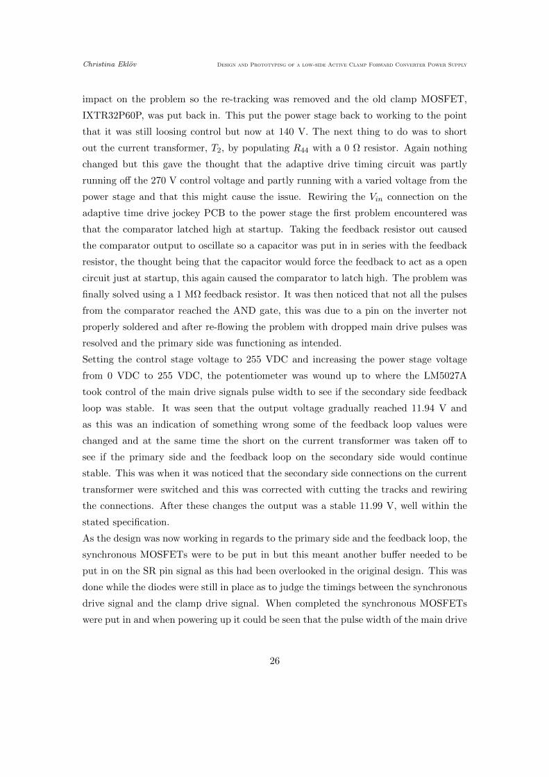
impact on the problem so the re-tracking was removed and the old clamp MOSFET,
IXTR32P60P, was put back in. This put the power stage back to working to the point
that it was still loosing control but now at 140 V. The next thing to do was to short
out the current transformer, T2, by populating R44 with a 0 Ω resistor. Again nothing
changed but this gave the thought that the adaptive drive timing circuit was partly
running off the 270 V control voltage and partly running with a varied voltage from the
power stage and that this might cause the issue. Rewiring the Vin connection on the
adaptive time drive jockey PCB to the power stage the first problem encountered was
that the comparator latched high at startup. Taking the feedback resistor out caused
the comparator output to oscillate so a capacitor was put in in series with the feedback
resistor, the thought being that the capacitor would force the feedback to act as a open
circuit just at startup, this again caused the comparator to latch high. The problem was
finally solved using a 1 MΩ feedback resistor. It was then noticed that not all the pulses
from the comparator reached the AND gate, this was due to a pin on the inverter not
properly soldered and after re-flowing the problem with dropped main drive pulses was
resolved and the primary side was functioning as intended.
Setting the control stage voltage to 255 VDC and increasing the power stage voltage
from 0 VDC to 255 VDC, the potentiometer was wound up to where the LM5027A
took control of the main drive signals pulse width to see if the secondary side feedback
loop was stable. It was seen that the output voltage gradually reached 11.94 V and
as this was an indication of something wrong some of the feedback loop values were
changed and at the same time the short on the current transformer was taken off to
see if the primary side and the feedback loop on the secondary side would continue
stable. This was when it was noticed that the secondary side connections on the current
transformer were switched and this was corrected with cutting the tracks and rewiring
the connections. After these changes the output was a stable 11.99 V, well within the
stated specification.
As the design was now working in regards to the primary side and the feedback loop, the
synchronous MOSFETs were to be put in but this meant another buffer needed to be
put in on the SR pin signal as this had been overlooked in the original design. This was
done while the diodes were still in place as to judge the timings between the synchronous
drive signal and the clamp drive signal. When completed the synchronous MOSFETs
were put in and when powering up it could be seen that the pulse width of the main drive
26

Christina Eklov Design and Prototyping of a low-side Active Clamp Forward Converter Power Supply
signal was minuscule and that the synchronous drive signal was not getting through to
the synchronous MOSFET. This was probably a problem with the adaptive drive timing
and/or the synchronous drive signal buffer but as the synchronous MOSFETs were put
in on the last day of the project there was no more time for fault finding and this was
where the design was left.
3.6 Results
The efficiency measured in the new design with diodes instead of the synchronous rec-
tification MOSFETs was 84% in comparison with the existing power supply that has
an efficiency of 83%. It should be noted though that for the existing power supply this
efficiency figure is for the entire power supply whereas for the new design it’s only for a
part of the power supply. In terms of component count the new design uses 160 compo-
nents with an approximate total price of £22.75, while the existing power supply uses
164 components with a total price of £20.51. The overall comparison can be seen in
Table 2 where the actual total size of the components have not been measured but a
visual estimate was made and as the synchronous rectification was not implemented the
noise and ripple measurements could not accurately be done on the new design.
Table 2. Collated points of comparison.
Characteristics for comparison Existing design New design Result
Efficiency 83% 84% New design more efficient
Number of components 164 pcs 160 pcs New design has less components
Size of components visual estimate visual estimate Equal size of total component count
Noise and ripple 9.08 mV not measured unknown
Cost £20.51 £22.75 Existing design is cheaper
27

Christina Eklov Design and Prototyping of a low-side Active Clamp Forward Converter Power Supply
4 Discussion
The results show that from an economic point of view the low side active clamp forward
converter in its current state is not an improvement on the existing power supply. This is
mainly due to the P-channel MOSFET which is approximately five times more expensive
then an equivalent N-channel MOSFET, and also the added cost of the adaptive drive
timing circuit.
Comparing the efficiency is more difficult as the design was never fully realized. It is
likely, if the synchronous rectification can be made to work, that the new design will
increase in efficiency to the degree where, even including the losses in the rest of the
power supply, it will be more efficient than the existing power supply. If so, even offset
against the increased relative cost this would make the new design a viable replacement.
Going forward, making the synchronous rectification work would be the first thing to
do. This would give a much clearer idea of the overall efficiency of the system. Another
thing to try to improve efficiency would be to do a price vs capacitance vs R(ds)on com-
parison for the main MOSFET as at this time the primary side is still hard switching
the MOSFET because of the MOSFET’s slow response due to high capacitance. Un-
fortunately MOSFETs with low capacitance have a higher R(ds)on resistance or higher
price. So this would be a balancing act, but is worth looking in to. An increase in
leakage inductance could also be a way of ensuring zero volt switching of the primary
side. If zero volt switching is achieved the RC-network on the clamp capacitor could
be looked at and possibly removed, again increasing efficiency and lowering the price,
although only marginally.
In the event that trying all the above still does not produce a useful design, a final
alternative approach would be to make the converter high side driven. The P-channel
clamp MOSFET could then be replaced with an N-channel MOSFET which would bring
the price down and hopefully the efficiency up. However, this would require a redesign
which would undoubtedly come with additional challenges, and so may not be a trivial
project.
28

Christina Eklov Design and Prototyping of a low-side Active Clamp Forward Converter Power Supply
5 Conclusion
The low side driven active clamp forward converter with synchronous rectification could
be a suitable replacement for the existing power supply design, providing improvement
of efficiency when the design is fully realized. As the design shows promise it would be
worth investing time to complete the prototype to establish its final performance.
29

Christina Eklov Design and Prototyping of a low-side Active Clamp Forward Converter Power Supply
References
[1] Analysis and Implementation of Low-side Active Clamp Forward Converters with
Synchronous Rectification [Online]. The 33rd Annual Conference of the IEEE Indus-
trial Electronics Society, Taipei, Taiwan, 2007. pp1506-1511.
[2] ”Voltage Mode Active Clamp Controller.” Texas Instruments, Dallas, TX, Datasheet
SNVS642B. 2013.
[3] ”AN-2067 LM5027A Evaluation Board.” Texas Instruments, Dallas, TX, User’s
Guide SNVA446B. 2014.
[4] ”Soft Ferrites and Accessories” Philips, Roswell, GA, Data Handbook. 2000.
[5] ”Power Supply Design Seminar” Unitrode, Merrimack, NH, SEM-1000 M5. 1994.
[6] ”Active Clamp Forward Controller and Gate Driver.” Linear Technology, Milpitas,
CA, Datasheet LT1113B. 2011.
30

22/08/2014 09:09:34 f=0.48 \\Filesrv2\psu_files\Power\Product Support\Eagle\Projects\Christina's\Thesis\VMAC\P-channel\v1.0\VMAC_v1.0.sch (Sheet: 1/1)
R1
20
6
R1
20
6
C1
81
2C
18
12
C1
81
2C
18
12
C2
211
C1
20
6
R1
20
6
R1
20
6
R1
20
6
R0
60
3
R0
60
3
R0
60
3
C0
60
3
R0
60
3
R0
80
5
C1
80
8
R0
60
3S
OT
23
C0
80
5
R0
60
3
R0
80
5
R0
80
5
R0
60
3
C0
60
3
R0
60
3C
06
03
R0
60
3
R0
60
3
C0
60
3
R0
80
5
C0
60
3
C0
60
3C
06
03
C0
60
3
R0603
R0
60
3
R0
60
3R
06
03
R0
60
3
C0
60
3C
06
03
C0
80
5
R1
20
6
R0
60
3
C1
21
0
R1
20
6
R0
60
3R
06
03
R0
60
3
C0
60
3S
OT
23
R2
51
2
R0
60
3R
06
03
R0
60
3
R0
60
3
R0
60
3R
06
03
R0
60
3
C0
80
5
C0
60
3
C0
60
3C
06
03
R0
60
3
R0
60
3
R0
60
3
R0
60
3
C0
60
3
C0
60
3
SO
T2
3
C0
40
2R
06
03
R0
60
3
R0
60
3
SO
T2
3
R0
80
5
25
0V
50
0V
50
0V
50
0V
50
0V
10
00
V
25
V
25
V
C1
20
6
C1
20
6
25
V
50
0V
50
0V
20
0V
50
0V
50
V
10
0V
50
V
25
V
25
V
25
V2
5V
50
V
25
V
25
V2
5V
25
V2
5V
50
V5
0V
50
V 50
V
50
V
R0
60
3C0
60
3
R0
60
3
R0
60
3
R0
60
3
R0
60
3
R0
80
5
R0
80
5
R1
20
6
R1
20
6
R1
20
6
R1
20
6
R0
60
3R
06
03
R0
60
3R
06
03
25
VC
E1
2C
E1
2
R0
60
3R
06
03
R0
60
3
R0
60
3
0.1
uF
0.1
uF
0.1
uF
0.1
uF
0.1
uF
0.1
uF
0.1
uF
0.1
uF
0.1
uF
0.1
uF 0V
SP
0V
PP
CH
AS
SIS
CH
AS
SIS
0V
SP
0R
0
0R
0
0R
0
0R
0
0R
0
LM
40
40
10
0p
F
1n
F
10
k
10
k
10
k1
0k
10k
0V
SC
10
0R
10
0R
BA
S1
6
BA
S1
6
24
R
75
pF
5R
6
5R
62
.2n
F
0V
SP
24
k3
3k
56
k
10
R
33
nF
47
nF
0.1
5u
F
1u
F
30
0R
30
0R
1.1
nF
1.1
nF
1k2
1k2
0V
SC
2k2O
PA
21
40
AID
OP
A2
14
0A
ID
0V
SC
4k7
1k6
18
0k
0V
SC
11
0p
F
82
pF
1n
F2
0k
15
0k
17
k4
8k2
1k3
47
k
2k2
BA
S1
6
0.2
2u
FC
ST
1-1
00L
P0
54
4
0R
0
0V
PC
0V
PC
VM
AC
_T
RA
FO
VM
AC
_T
RA
FO
1-1
37
95
0V
SC
SP
O
0R
0
0R
0
47
pF
47
pF
2k2
2k2
15
0p
F
47
k
1M 2
k
36
k
18
k
33
0p
F
SP
O
IXT
R3
2P
60
P
FD
P3
65
2
FD
P3
65
2
0R
0
2.2
uF
2.2
uF
SP
O
SP
O
SP
O
0R
00
R0
0R
00
R0
24
k2
7k
56
k
BA
T5
4A
BA
T5
4A
SF
H6
15
6-2
10
R
10
R
1M
0
1M
0
47
k
47
k
D-SUB25-H2M25ST
LM
5027A
-20
0V
PC
CH
AS
SIS
AM
PH
EN
OL
_H
YB
RID
_D
'SU
B_
17
W2
18
0u
F1
80
uF
D-S
UB
15
-H2
M1
5S
T
0V
SP
SP
O0
R0
0R
0
4k3
C1
C2
C3
C4
C5
C6
C7
C8
C9
C1
0
R2
R4
R5
R6
R7
21
IC5
C1
2
C1
4
R1
2
R1
3
R1
4R
15
R16
R1
7
R1
8
R1
9 0R
00
5
D1
D2
R2
0
C1
5
R2
1
R2
2C
16
R2
3R
24
R2
6
R2
7
C1
7C
18
C1
9
C2
0
R2
8R
29
C2
3C
24
R3
0R
31
R3
2
231
8 4
IC4
A
657
IC4
B
R3
3
R3
4
R3
5C
25
C2
6
C2
7R
36
R3
7
R3
8
R3
9
R4
0
R4
1
R4
2
D3
C2
8P
$8
P$7
P$3
P$1
P$4
P$6
T2
P$1
P$8
P$5
P$4
P$6
P$3
T3
R4
3
P1
P3
P4
P6
P7
P9
P10
P12
T1
P13
P14
T1
20
21
L1
R4
4
VC
C
IN+
IN-
0V
N_O
UT
P_O
UT
IC2
MA
X5
04
8A
VC
C
IN+
IN-
0V
N_O
UT
P_O
UT
IC3
MA
X5
04
8A
R1
R4
5
C2
9
C3
0R
46
R4
7
C11
R8
R9
R1
0
R11
R3
C1
3
C3
1T
R1
TR
2
TR
4
TR
3
R4
8
C3
2
C3
3
C3
4
C3
5
R4
9
R5
0R
51
R5
2R
53
R5
4R
55
R2
5
D5
D4
P$2
P$1
P$3
P$4
IC6
R5
6
R5
7
R5
8
R5
9
R6
0
R6
1
PL
1-1
PL
1-2
PL
1-3
PL
1-4
PL
1-5
PL
1-6
PL
1-7
PL
1-8
PL
1-9
PL
1-1
0P
L1
-11
PL
1-1
2P
L1
-13
PL
1-1
4P
L1
-15
PL
1-1
6P
L1
-17
PL
1-1
8P
L1
-19
PL
1-2
0P
L1
-21
PL
1-2
2P
L1
-23
PL
1-2
4P
L1
-25
VIN
1
RA
MP
2
TIM
E3
3
TIM
E2
4
TIM
E1
5
AG
ND
6
RT
7
CO
MP
8
RE
F9
OU
TB
10
OU
TA
11
OU
TS
R12
PG
ND
13
VC
C14
UV
LO
20
OT
P19
SS
SR
18
RE
S17
SS
16
CS
15
IC1
PA
D21
11
22
33
44
55
66
77
88
1
SK
1
99
10
10
1111
12
12
13
13
14
14
15
15
A1
A1
A2
A2
C2
2C
21
PL
2-1
PL
2-2
PL
2-3
PL
2-4
PL
2-5
PL
2-6
PL
2-7
PL
2-8
PL
2-9
PL
2-1
0P
L2
-11
PL
2-1
2P
L2
-13
PL
2-1
4P
L2
-15
R6
2R
63
R6
4
R6
5
CL
K
VA
UX
P
VA
UX
VA
UX
VA
UX
VA
UX
_R
TN
VA
UX
_R
TN
VR
EF
VR
EF
VO
UT
+
0V
SP
VO
UT
+F
B
VO
UT
+F
B
VA
UX
P_
RT
N
VB
OO
ST
0V
PP
CH
AS
SIS
_S
BO
OS
T_
OV
BO
OS
T_
OV
+1
2V
_A
DJ+1
2V
_A
DJ
TE
MP
_A
DJ
TE
MP
_A
DJ
IN_
V_
FA
ILIN_
V_
FA
IL
0V
S
0V
S
0V
S
I2C
_R
ES
ET
I2C
_R
ES
ET
I2C
_S
DA
I2C
_S
DA
I2C
_S
CL
I2C
_S
CL
PW
R_
SH
UT
D
PW
R_
SH
UT
D
PRI
S1S2
CL
IP
+
+
Christina Eklov Design and Prototyping of a low-side Active Clamp Forward Converter Power Supply
Appendix A
A1

30/08/2014 13:43:52 f=0.48 \\Filesrv2\psu_files\Power\Product Support\Eagle\Projects\Christina's\Thesis\VMAC\P-channel\v2.0\VMAC_v2.0.sch (Sheet: 1/1)
R1
20
6
R1
20
6
C1
81
2C
18
12
C1
81
2C
18
12
C2
211
C1
20
6
R1
20
6
R1
20
6
R1
20
6
R0
60
3
R0
60
3
R0
60
3
C0
60
3
R0
60
3
R0805
C1
21
0
R0
60
3S
OT
23
C0
80
5
R0
60
3
R0
80
5
R0
80
5
R0
60
3
C0
60
3
R0
60
3
R0
60
3
C0
60
3
R0
80
5
C0
60
3
C0
60
3C
06
03
C0
60
3
R0
60
3
R0
60
3
R0
60
3R
06
03
R0
60
3
C0
60
3C
06
03
C0
80
5
R1
20
6
R0
60
3
C1
21
0
R1
20
6
R0
60
3R
06
03
R0
60
3
C0
60
3S
OT
23
R2
51
2
R0
60
3R
06
03
R0
60
3
R0
60
3
R0
60
3R
06
03
R0
60
3
C0
80
5
C0
60
3
C0
60
3C
06
03
R0
60
3
R0
60
3
R0
60
3
R0
60
3
C0
60
3
C0
60
3
SO
T2
3
C0
40
2R
06
03
R0
60
3
R0
60
3
SO
T2
3
R0
80
5
25
0V
50
0V
50
0V
50
0V
50
0V
10
00
V
25
V
25
V
C1
20
6
C1
20
6
25
V
50
0V
50
0V
20
0V
50
0V
10
0V
50
V
25
V
25
V
25
V2
5V
50
V
25
V
25
V2
5V
25
V2
5V
50
V5
0V
50
V 50
V
50
V
R0
60
3
C0
60
3
R0
60
3
R0
60
3
R0
60
3
R0
60
3
R0
80
5
R0
80
5
R1
20
6
R1
20
6
R1
20
6
R1
20
6
R0
60
3R
06
03
R0
60
3R
06
03
25
VC
E1
2C
E1
2
R0
60
3
R0
60
3R
06
03
R0
60
3
C1
80
8
C1
80
8
10
00
V
10
00
V
C0
60
35
0V
C0
60
35
0V
R0
60
3
C0
60
35
0V
C0
60
32
5V
C1
21
05
00
V
C0
60
3R
08
05
R0
80
5
C0
60
3R
06
03
C1
20
62
5V
50
0V
R0
80
5
R2
51
2
0.1
uF
0.1
uF
0.1
uF
0.1
uF
0.1
uF
0.1
uF
0.1
uF
0.1
uF
0.1
uF
0.1
uF 0V
SP
0V
PP
CH
AS
SIS
CH
AS
SIS
0V
SP
0R0
0R
0
0R
0
5R
6
LM
40
40
1n
F
10
k1
0k
10
k2
k2
10
k
0V
SC
10
0R
10
0R
BA
S1
6
BA
S1
6
24
R
47
0p
F
5R
6
5R
64
7n
F
0V
SP
62
k5
6k
47
k
10
R
33
nF
47
nF
0.1
5u
F
1u
F
30
0R
30
0R
1.1
nF
1.1
nF
1k2
1k2
0V
SC
2k2
OP
A2
14
0A
IDO
PA
21
40
AID
0V
SC
4k7
15
0k
91
k
0V
SC
47
0p
F
68
0p
F
22
nF
10
k
15
0k
17
k4
8k2
1k3
47
k
2k2
BA
S1
6
0.2
2u
FC
ST
1-1
00L
P0
54
4
0R
0
0V
PC
0V
PC
VM
AC
_T
RA
FO
VM
AC
_T
RA
FO
1-1
37
95
0V
SC
SP
O0
R0
0R
0
27
pF
27
pF
1k
1k
15
0p
F
47
0k
1M
0 2k
36
k
18
k
33
0p
F
10
nF
SP
A11
N6
0C
3
IXT
R3
2P
60
P
FD
P3
65
2
FD
P3
65
2
0R
0
2.2
uF
2.2
uF
10
nF
4n
7
75
0R
0R
00
R0
0R
00
R0
13
k2
7k
56
k
BA
T5
4A
BA
T5
4A
SF
H6
15
6-2
10
R
10
R
1M
0
1M
0
47
0k
47
0k
D-SUB25-H2M25ST
LM
5027A
-20
0V
PC
CH
AS
SIS
AM
PH
EN
OL
_H
YB
RID
_D
'SU
B_
17
W2
18
0u
F1
80
uF
D-S
UB
15
-H2
M1
5S
T
0V
SP
SP
O
0R
00
R0
4k3
10
nF
0.1
uF
10
0R
10
nF 0V
SC
0.1
uF
BA
S1
6
2.2
uF
LP
29
81
M5
0.1
uF
10
uF
TLV
3201_
910k
910k
910k
910k
910k
910k
33k
36k
1k5
1k5
1k
1k
10
nF
vari
SPO
1k5
1k
100R
0.1
uF
1M
0
NC
7S
T0
4
NC
7S
T0
4
NC
7S
T0
4
74A
CT
08S
C
0.1
uF
0.1
uF
0.1
uF
0R
00
R0
27
pF
1k
2.2
uF
10
R
0V
PC
0V
PC
0V
PC
0V
PC
0V
PC
0V
PC
0V
PP
0V
PP
0V
PP
C1
C2
C3
C4
C5
C6
C7
C8
C9
C1
0
R4
R5
R6
R7
21
IC5
C1
3
R1
2R
13
R1
4R
15
R1
6
R1
7
R1
8
R1
9 0R
00
5
D1
D2
R2
0
C1
4
R2
1
R2
2C
15
R2
3R
24
R2
6
R2
7
C1
6C
17
C1
8
C1
9
R2
8R
29
C2
2C
23
R3
0R
31
R3
2
231
8 4
IC4
A
657
IC4
B
R3
3
R3
4
R3
5C
24
C2
5
C2
6R
36
R3
7
R3
8
R3
9
R4
0
R4
1
R4
2
D3
C2
7P
$8
P$7
P$3
P$1
P$4
P$6
T2
P$1
P$8
P$5
P$4
P$6
P$3
T3
R4
3
P1
P3
P4
P6
P7
P9
P10
P12
T1
P13
P14
T1
20
21
L1
R4
4
VC
C
IN+
IN-
0V
N_O
UT
P_O
UT
IC2
MA
X5
04
8B
VC
C
IN+
IN-
0V
N_O
UT
P_O
UT
IC3
MA
X5
04
8B
R1
R4
5
C2
8
C2
9R
46
R4
7
C11
R8
R9
R1
0
R11
R3
C1
2
C3
0
TR
1
TR
2
TR
4
TR
3
R4
8
C3
1
C3
2
C3
3
C3
4
R4
9
R5
0R
51
R5
2R
53
R5
4R
55
R2
5
D5
D4
P$2
P$1
P$3
P$4
IC6
R5
6
R5
7
R5
8
R5
9
R6
0
R6
1
PL
1-1
PL
1-2
PL
1-3
PL
1-4
PL
1-5
PL
1-6
PL
1-7
PL
1-8
PL
1-9
PL
1-1
0P
L1
-11
PL
1-1
2P
L1
-13
PL
1-1
4P
L1
-15
PL
1-1
6P
L1
-17
PL
1-1
8P
L1
-19
PL
1-2
0P
L1
-21
PL
1-2
2P
L1
-23
PL
1-2
4P
L1
-25
VIN
1
RA
MP
2
TIM
E3
3
TIM
E2
4
TIM
E1
5
AG
ND
6
RT
7
CO
MP
8
RE
F9
OU
TB
10
OU
TA
11
OU
TS
R12
PG
ND
13
VC
C14
UV
LO
20
OT
P19
SS
SR
18
RE
S17
SS
16
CS
15
IC1
PA
D21
11
22
33
44
55
66
77
88
1
99
10
10
1111
12
12
13
13
14
14
15
15
A1
A1
A2
A2
SK
1
C2
1C
20
PL
2-1
PL
2-2
PL
2-3
PL
2-4
PL
2-5
PL
2-6
PL
2-7
PL
2-8
PL
2-9
PL
2-1
0P
L2
-11
PL
2-1
2P
L2
-13
PL
2-1
4P
L2
-15
R6
2
R6
3R
64
R6
5
C3
5
C3
6
R6
8
C3
7
C3
8
D6
C3
9
VIN
1
ON
3
VO
UT
5
GN
D2
U2
C4
0C
41
5
IN+
3
IN-
4
2
OU
T1
U1
R69
R70
R71
R72
R73
R74
R75
R76
R7
7R
78
R79
R80
C4
2
C4
3
R81
R8
2R83
R84
C4
4
R8
5
24
U$
1 VC
C5
GN
D3
24
U$
2 VC
C5
GN
D3
24
U$
3 VC
C5
GN
D3
VC
C14
A0
1
A1
4
A2
13
A3
10
B0
2
B1
5
B2
12
B3
9
GN
D7
O1
6
O0
3
O2
11
O3
8
U4
C4
5
C4
6
C4
7R
86
VC
C
IN+
IN-
0V
N_O
UT
P_O
UT
IC7
MA
X5
04
8B
R8
7
C4
8R
88
C4
9
R8
9
R2
68
0R
VA
UX
P
VA
UX
VA
UX
VA
UX
VA
UX
_R
TN
VA
UX
_R
TN
VR
EF
VR
EF
VO
UT
+
0V
SP
VO
UT
+F
B
VO
UT
+F
B
VA
UX
P_
RT
N
CH
AS
SIS
_S
BO
OS
T_
OV
BO
OS
T_
OV
+1
2V
_A
DJ+1
2V
_A
DJ
TE
MP
_A
DJ
TE
MP
_A
DJ
IN_
V_
FA
ILIN_
V_
FA
IL
0V
S
0V
S
0V
S
I2C
_R
ES
ET
I2C
_R
ES
ET
I2C
_S
DA
I2C
_S
DA
I2C
_S
CL
I2C
_S
CL
PW
R_
SH
UT
D
PW
R_
SH
UT
D
CL
OC
K
VS
WIT
CH
VB
OO
ST
VB
OO
ST
GN
D1
PRI
S1S2
CL
IP
+
+
+
Christina Eklov Design and Prototyping of a low-side Active Clamp Forward Converter Power Supply
Appendix B
B1