design and production of mini-formula machines for education of...
TRANSCRIPT

Mongolia-Korea Joint Workshop on CAD/CAM (2007)
Design and Production of Mini-Formula Machines for Education of CAD/CAM
Sang Hun Lee School of Mechanical and Automotive
Engineering Kookmin University
Seoul, Korea +82-2-910-4835
Kun Sang Lee School of Mechanical and Automotive
Engineering Kookmin University
Seoul, Korea +82-2-910-4717
Kang-Soo Lee School of Mechanical Engineering
Hanbat National University Daejeon, Korea
+82-42-821-1086
Abstract This paper introduces a course term project for design and production of a mechanical product for the purpose of more practical CAD/CAM and design education. Two kinds of mini-formula machines, F-125 and Formula SAE, were selected for the project. They were designed and produced using so called 3D (three-dimensional) PLM systems that include CAD, CAM, CAE, PDM, and DMU systems. Here, the F-125 machine is a formula racing car equipped with a 125cc motorcycle engine, and the Formula SAE machine is a car with a less than 610cc engine and following the regulations of SAE. A development process and a computer-integrated environment using 3D PLM systems were established on the basis of concurrent and virtual engineering technologies. A DMU model for a full vehicle was built using CATIA V.5 and used to check interference in the parts and to simulate the assembly process. The DMU-based approach enables to find and fix manufacturing problems in the early design stage. All the development activities have been done by the graduate and undergraduate students of the automotive engineering department of Kookmin University. Through the project, the students could get a wide knowledge about the car development process and develop their skills at 3D PLM systems used in automotive industry.
Keywords: education, CAD/CAM, formula machine, design.
1. Introduction Recently automobile companies strive to shorten the lead-time in product development in order to survive in the global market by satisfying customers’ needs [7, 14]. For this purpose, different kinds of computer-aided tools such as CAD, CAE, CAM, PDM and DMU systems are widely accepted in the companies [2, 3, 4, 6, 10, 11]. Recently, all of the tools supporting the product lifecycle management are termed 3D PLM systems by the software vendors. In this context, the educators of engineering colleges need to develop a course that not only skills but also underlying principles for 3D PLM systems can be delivered effectively to the students. To achieve this goal, in Kookmin University renowned for its automotive engineering school, a curriculum for 3D PLM has been developed, in which there is a design course to design, produce, and compete mini-formula machines as a term project [5, 13]. In this paper, we introduce this
term-project and discuss its effects in the view of CAD/CAM education.
2. Environment Setup 2.1 Computing Environment The purpose of the term project is to make the students develop their skills for the 3D PLM systems as well as product design. The students need to utilize various computer systems to accomplish this goal. In the course, they are provided with an opportunity for using a wide range of 3D PLM systems and experiencing a state-of-the-art product development process in automotive industry.
IBM PC IBM PC IBM PC
IBM PC IBM PC IBM PC
Computer Lab.
PDM : TeamPDMDB : OracleCAD : Catia V5, I-DEASDMU : VisMockupCAM : Z-MasterCAE : Adams, DFMA, CFD-ACE+VR : Stereo View (emitter, glass)
HP Server
Lab 1 NVH Lab. Lab nLab 2
...
...
...
AnsysNastranHyperMeshI-DEAS
DADSPamCrash Star CD
CAD Lab
RapidFormRealScan 3D
Figure 1. Computing environment.
158

Mongolia-Korea Joint Workshop on CAD/CAM (2007)
To support this term project, a laboratory consisting of various computer-aided systems was constructed. In the laboratory, 47 copies of CATIATM were installed as a CAD/CAM system, which plays the most important role in design. 30 copies of RapidFormTM and one RealScan 3DTM device were installed for 3-D shape reverse engineering. TeamPDMTM of Dassault Systems was selected as a PDM (product data management) system and installed in each computer equipped with CATIA. As CAE systems, ADAMSTM, DFMATM, CFD-ACE+TM, Star CDTM, AnsysTM, NastranTM, HyperMeshTM, PamCrashTM and DADSTM were prepared.
2.2 Virtual Engineering Environment In order to apply virtual engineering technology in developing a product, we should integrate various kinds of computer-aided systems and customize a lot of modules that have not been formulized. We planned to construct the related system as shown in Figure 2.
Testing
Application BasedDMU
DMU for Manufacuring
Some Hardwares/Softwares
CAE
PMU (Physical Mockup)
Generic DMU (3D Solid Shape in CAD Systems)
DMU for Ride & HandlingDMU for Crash & Safe
DMU for NVHDMU for DurabilityDMU for Strength
DMU for Visualization .
CAD CAM CAT
Virtual Design
. Virtual Manufacturing
Virtual Testing
Virtual Marketting/Purchasing/Publishing/Collaboration
Virtual Design Room
Virtual Factory .
Virtual Testing Room CAM CAE
CAM CAE
As-Is process based on loosely intehrately integrayed computer systems
To-Be process based on virtual engineering and integrated conputer systems
general process without data flow
Figure 2. System architecture for virtual engineering
The lower part of Figure 2 shows the utilization of computer-aided systems in developing a product. The engineers design a product by using CAD systems such as CATIATM, analyze the product by using CAE systems with the CAD data, and generate NC data from the CAD data. Although there are some interface problems, ideally it is possible to use them seamlessly. Prototypes are produced after some activities such as manufacturing, purchasing and assembly. The design may be modified. If necessary, the same process is applied to the second design, such as manufacturing, purchasing, assembly and testing.
The upper part of Figure 2 represents the process to virtual engineering based on the current computer systems. The prototypes generated on the computer systems are called digital mockups (DMU) [9] in contrast to the physical prototypes. The data generated in the solid modeling system is generic DMU [10], which will be used throughout the whole virtual process, that is, virtual design, virtual manufacturing and virtual testing. In contrast to the generic DMU, the DMUs used in the specific areas such as virtual design, virtual manufacturing and virtual testing are called application-based DMUs [12]. The application-based DMUs retrieve data from the generic DMU and add more information for their engineering activities.
2.3 PDM System A PDM system is a computer-based system that supports management of engineering data and process. This system also provides support for the activities of product teams and for the techniques, such as concurrent engineering, that aim to improve engineering workflow.
In this project, TeamPDM integrated in CATIA V.5 was selected as a PDM system and InterBase was chosen as the DBMS system underlying TeamPDM from the candidates including Oracle, MS SQL Server, InterBase, and DB2. Figure 3 shows the user interface of the PDM system. All the CAD data and engineering documents are managed by this system.
Figure 3. PDM system (customization of TeamPDMTM).
3. Team Organization As shown in Figure 4, seven teams were organized and managed by a project manger (PM). The role of each team is as follows.
Figure 4. Organization of project teams
Research & Planning Team
DMU Team
Frame Team
Steering & Suspension
Power-Train Team
Manufacturing Team
Styling Team
Project Manager
159

Mongolia-Korea Joint Workshop on CAD/CAM (2007)
- Research and Planning (R&P) Team: product planning, management of PDM system, ergonomic design and review, purchase, electric and electronic parts
- Frame Team: design and analysis of the frame. - Steering and Suspension (S&S) Team: design and analysis of
chassis system including steering and suspension system. - Power-Train (PT) Team: design and analysis of engine and
transmission. - DMU Team: construction and management of DMU. - Manufacturing Team: production of the car. - Styling Team: industrial design of cowl. (This team is
organized by the students majoring in industrial design.)
4. Design 4.1 Product Planning The product is planned by using the QFD (Quality Function Deployment) technology [7, 14]. Some requirements are converted as numeric target values that support the engineer’s decision. The QFD tables prepared in planning are used and modified until the project is finished.
4.2 Ergonomic Design Ergonomics is applied to the design of the cockpit module including pedals, a steering wheel, a seat, and a manual stick. We used Human Module of CATIA V.5 for ergonomic assessment. A virtual mannequin is created according to the dimensions of the driver’s body in CATIA V.5 first, and then the ergonomic assessment process is carried out. The position of the steering wheel, pedals, and manual stick are determined through the virtual ergonomic assessment. Figure 5 shows the simulation result that the seat is not suitable for driver’s body.
Figure 5. Ergonomic assessment for seat design.
4.3 Styling The frame team creates and hands a draft for the frame over to the styling team. Based on the draft, the styling team makes tens of sketches for the cowl, and selected a few ones from them to create 3-D surface models using AliasTM. The 3-D models are assessed and one of them is selected as the final cowl model to be produced. All the model evaluation is done in virtual environment. The final styles for F-125 and Formula SAE are shown in Figure 6.
(a) (b)
Figure 6. Styling for the cars: (a) F-125, (b) Formula SAE.
4.4 Frame Design A stronger, lighter, safer, more endurable frame is highly desirable for a racing car. In particular, a light but strong frame is important for overtaking the other cars in a race. The frame is designed three-dimensionally using CATIA V.5. The analyses for the frame are performed for strength and vibration modes using NASTRAN and PATRAN, and for crash using PAM-CRASH. The mesh models for analyses are generated using HYPERMESH. An iterative design and analysis cycle in this project is illustrated in Figure 7.
Figure 7. Frame design and analysis cycle.
4.5 Design of Steering and Suspension System The steering system is designed to show neutral or over-steering characteristic, which is desirable for racing [15]. The steering ratio is chosen 3:1. The double wishbone in body type is selected for the suspension system. All the steering and suspension system is three-dimensionally modeled using CATIA V.5, and simulated using ADAMS/Car and ADAMS/insight. The ADMS model for the front suspension and steering system is shown in Figure 8(a), and the kinematics and compliance (K&C) test machine is shown in Figure 8(b). The K&C analysis is carried out using ADAMS. The ride, roll, and steering characteristics are analyzed in the kinematics analysis phase, and the aligning torque compliance and lateral force compliance are simulated in the compliance analysis phase. Figure 9 shows an analysis result for ride mode. The vehicle dynamics simulation was also performed using ADAMS. The mass properties are calculated using CATIA, and the characteristics of tires and bushings are collected from the published data for similar cars. Simulation is carried out for J-turn, ISO lance change, and constant radius cornering as illustrated in Figure 10.
160

Mongolia-Korea Joint Workshop on CAD/CAM (2007)
(a) (b)
Figure 8. Front suspension system: (a) an ADMS model, (b) a kinematics and compliance (K&C) tester.
Figure 9. ADAMS analysis results for ride toe angles
Figure 10. J-turn simulation using ADAMS/Car.
4.6 Digital Mockup(DMU) All the subassemblies modeled using CATIA V.5 by the design teams are gathered together to construct a whole assembly called DMU. The problems on the product in the manufacturing stage, such as part interference, can be detected in advance using DMU. The fitting process also can be simulated.
(a)
(b) (c)
Figure 11. DMU models: (a) detecting a problem on fixing the engine, (b) DMU of the F-125 machine, (c) DMU of the Formula SAE machine.
5. Production 5.1 Production of Cowl The cowl is usually made of fiberglass reinforced plastics (FRP). For a FRP cowl, the Styrofoam pattern is made by hand, and then a plaster mold for the cowl is made from the pattern. However, in this project, we introduced a CNC milling machine for cutting the Styrofoam pattern. As shown in Figure 12, a solid model for the cowl is split into two parts according to the tool length, and then NC tool paths were generated using the CAM module of CATIA V.5. Two solid models are machined and then glued together to complete the pattern as shown in Figure 13. Finally, the FRP cowl is made and painted as shown in Figure 14.
Figure 12. NC tool path generation for the Styrofoam pattern.
(a) (b)
Figure 13. Cowl production: (a) Styrofoam pattern, (b) finishing and painting work.
5.2 Production of Frame and Chassis The frame is completed by welding the steel segments together as shown in Figure 14. The suspension and powertrain systems are assembled by welding and bolting the parts together according to the assembly process plan.
161
Mongolia-Korea Joint Workshop on CAD/CAM (2007)
(a) (b)
(c) (d)
Figure 14. Production of the frame and chassis systems: (a) the frame, (b) the workshop, (c) the suspension, (d) the powertrain.
5.3 Final Assembly The sub-assemblies including the frame, chassis, and cowl are all assembled to complete the mini-formula machine. Figure 15 shows the F-125 and Formula SAE machines completed finally.
(a) (b)
Figure 15. Completed cars: (a) the F-125 machine, (b) the Formula SAE machine.
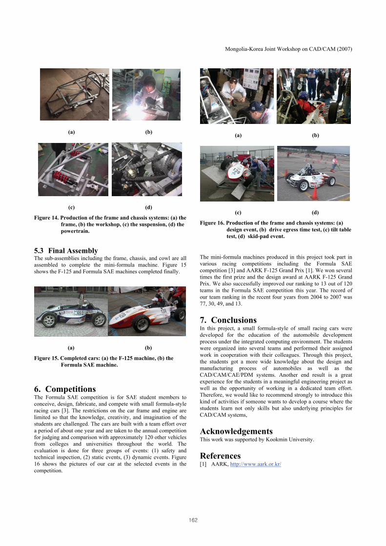
6. Competitions The Formula SAE competition is for SAE student members to conceive, design, fabricate, and compete with small formula-style racing cars [3]. The restrictions on the car frame and engine are limited so that the knowledge, creativity, and imagination of the students are challenged. The cars are built with a team effort over a period of about one year and are taken to the annual competition for judging and comparison with approximately 120 other vehicles from colleges and universities throughout the world. The evaluation is done for three groups of events: (1) safety and technical inspection, (2) static events, (3) dynamic events. Figure 16 shows the pictures of our car at the selected events in the competition.
(a) (b)
(c) (d)
Figure 16. Production of the frame and chassis systems: (a) design event, (b) drive egress time test, (c) tilt table test, (d) skid-pad event.
The mini-formula machines produced in this project took part in various racing competitions including the Formula SAE competition [3] and AARK F-125 Grand Prix [1]. We won several times the first prize and the design award at AARK F-125 Grand Prix. We also successfully improved our ranking to 13 out of 120 teams in the Formula SAE competition this year. The record of our team ranking in the recent four years from 2004 to 2007 was 77, 30, 49, and 13.
7. Conclusions In this project, a small formula-style of small racing cars were developed for the education of the automobile development process under the integrated computing environment. The students were organized into several teams and performed their assigned work in cooperation with their colleagues. Through this project, the students got a more wide knowledge about the design and manufacturing process of automobiles as well as the CAD/CAM/CAE/PDM systems. Another end result is a great experience for the students in a meaningful engineering project as well as the opportunity of working in a dedicated team effort. Therefore, we would like to recommend strongly to introduce this kind of activities if someone wants to develop a course where the students learn not only skills but also underlying principles for CAD/CAM systems,
Acknowledgements This work was supported by Kookmin University.
References [1] AARK, http://www.aark.or.kr/
162

Mongolia-Korea Joint Workshop on CAD/CAM (2007)
[2] Bauer, M. D. and Rosen., D. W., An Approach to Integrated Product/Process Design via Virtual Prototyping. In Proceedings of 1997 ASME Design Engineering Technical Conferences, DETC97/DAC-3394, 1997.
[3] Formula SAE, http://students.sae.org/competitions/formulaseries/fsae/
[4] Gowda, S., Jayaram, S. and Jarayam, U., Architectures for Internet-Based Collaborative Virtual Prototyping. In Proceedings of 1999 ASME Design Engineering Technical Conferences, DETC99/CIE-9940, 1999.
[5] GSAEK , Proposal to educate high-grade students for preparing knowledge based technology, 1999. (in Korean)
[6] Han, S.H., et al, Report on the technology used for shortening the lead-time in developing new cars, 1998. (in Korean)
[7] Hartley, J. R., Concurrent Engineering: Shortening Lead Times, Easing Quality, and Lowering Costs, Productivity Press, 1998.
[8] Heo, S. J., Survey on the application of virtual engineering to automotive development. In Proceedings of a symposium on automotive technology, 1999. (in Korean)
[9] Lee, K., Principles of CAD/CAM/CAE Systems, Addison Wesley, 1999.
[10] Lee, K.-S., Automobile development by using IT technology. Technical report of GSAEK, 2000. (in Korean)
[11] Lee, K.-S., et al, A case of digital mockup system implementation for improving product development process. In Proceedings of 2000 Korean CAD/CAM Conference, 2000, 247-252. (in Korean)
[12] Lee, K.-S. and Lee, S.H., Development of a DMU System Based on a PDM System. Transactions of Society of CAD/CAM Engineers, 8, 9 (Sep. 2003) 157-166. (in Korean)
[13] Lee, S.H. and Lee, K.-S., Development of an F-125 Machine Using 3D PLM Systems. Transactions of Society of CAD/CAM Engineers, 10, 2 (Apr. 2005) 77-88. (in Korean)
[14] Prasad, B. , Concurrent Engineering Fundamentals, Prentice Hall, 1996.
[15] Miller, W.F. and Miller, D.L., Race Car Vehicle Dynamics, SAE, 1997.
163