design and planning of lai chi kok transfer scheme, …
TRANSCRIPT

1
DESIGN AND PLANNING OF LAI CHI KOK TRANSFER SCHEME, HONG
KONG
Alan W.C. Ip1, Eddie W.C. Lam1, Peter, C.W. Cheung1
1Drainage Services Department, Government of Hong Kong SAR, China
KEYWORDS
drainage tunnel, TBM, risk management
ABSTRACT
The Lai Chi Kok Transfer Scheme comprising a 4.9m finished diameter, 3.7km long drainage tunnel with associated intake/outlet shafts and connection adits was initiated by the Government of Hong Kong Special Administrative Region to reduce flood risk in a dense urban area. The project involves construction of two TBM tunnels through hard rock stratum with a number of transverse fault zones, and mixed ground under high ground water table. Along the tunnel alignment are existing buildings, railway lines, major trunk roads and highway viaducts at a minimal clearance. This paper provides an overview of the site conditions and constraints, selection of tunnel alignment and TBMs, and resolution with stakeholders on land and technical issues. Protection of existing structures/utilities, design considerations, hybrid design-and-build contract with re-measurement provisions for control of groundwater infiltration, risk management and adoption of geotechnical baseline report will also be discussed.
INTRODUCTION
Rapid urbanization and changes in land use in the developed districts of Sham Shui Po, Cheung Sha Wan and Lai Chi Kok over the past decades have turned natural ground and slopes into paved and impermeable areas. During heavy rainstorms, large quantity of surface run-off from the hinterland and the overflow from Kowloon group of reservoirs will flow into the downstream urban areas and overload the existing drainage systems. As a result, flooding often occurs during heavy rainstorms resulting in traffic disruption, property damages and safety risk to public. To alleviate the problem, the Government of the Hong Kong Special Administrative Region has formulated the Lai Chi Kok Transfer Scheme (LCKTS) which forms an integral part of the overall flood control strategy for West Kowloon. The drainage tunnel of the LCKTS will intercept surface run-off from the West Kowloon hinterland and potential overflow from the Kowloon group of reservoirs for discharge directly to Victoria Harbour. By diverting the upland flow to the proposed drainage tunnel, extensive drainage upgrading works in the congested lower catchment urban areas can be substantially reduced. Upon completion of the proposed LCKTS, the standard of flood protection in downstream urban area will be improved generally to withstand rainstorms with a return period of one in 50 years.
PROJECT SCOPE
The scope of the project comprises the construction of:

2
Two drainage tunnels - Main Tunnel (1.2 km) and Branch Tunnel (2.5 km) with
4.9m internal diameter; Six drop shafts, and five connecting adits at a total length of 270m; A stilling basin, an outfall structure and two 10m diameter and 40m deep
inlet/outlet shafts ; Six intake structures and associated slope stabilization works; and Surface drainage system and ancillary E&M equipments.
A layout plan and longitudinal section showing the tunnel alignment and the location of the proposed works are shown in Figure 1 and Figure 2. The works commenced in November 2008 for completion in end 2012.
Figure 1. Tunnel Alignment and location of Works
Figure 2. Inferred Geological Profile and Vertical Alignment (Vertical Scale Schematic)

3
ANTICIPATED GROUND CONDITIONS
The tunnels run through mainly within coarse, medium and locally fine grained granitic rock formed in the Jurassic-Cretaceous Period. A number of fault zones and shear zones have been identified to intersect the tunnel alignment. Many of these geological features contain highly fractured ground with blocky bedrock and mixed ground with a variable thickness of fault gouge. The bedrock material is predominantly very strong and abrasive granite with average Unconfined Compressive Strength (UCS) of 200 MPa and a maximum value of 325 MPa (see Figure 3). The granite is intruded with a variety of cross-cutting dykes. The Branch Tunnel will be excavated primarily through bedrock except at portal and at the locations of some weathered faults with the presence of colluviums, residual soils and completely to highly decomposed granite of varying thickness. In the Main Tunnel, superficial deposits of Quaternary age overlie the solid geology. These comprise, in layering order, reclamation fill, marine deposits and alluvium. The bedrock varies from highly fractured to massive and contains zones of blocky ground. About 700m in length of the Main Tunnel will pass through mixed/soft ground which may contain variable proportion of corestones (see Figure 2).
Figure 3. Distribution of UCS Test Results
Groundwater
The terrain along the Branch Tunnel is highly varied affecting the groundwater table which generally lies within 1m of rockhead level. The Main Tunnel situated underneath reclaimed land with a high groundwater table between 1 to 2m below existing ground level. Due to proximity to the sea, ground water table along the Main Tunnel alignment is significantly affected by the sea level and tidal effects.
GROUND INVESTIGATION
Four phases of project specific ground investigation (GI) works have been carried out comprising 112 vertical borings, 24 inclined borings, 2 coreholes, 72 trial pits and 1 horizontal boring; in average about 27m length of tunnel per boring. The explorations aimed to obtain comprehensive coverage of GI data along the tunnel route and at some sensitive locations to ascertain the rockhead level. The inclined borings were specifically intended to investigate inferred shear zones and faults. Apart from standard laboratory testing to determine rock and soil properties including permeability,

4
compressibility and chemical properties, specialist tests for TBM tunneling covering borability and abrasive tests such as Cerchar Abrasivity Index were carried out. It was considered that the project specific GI together with archival GI data obtained from 250 borings in the vicinity of tunnel route should provide sufficient subsurface information for the planning, design and construction of the tunnels. Nevertheless, additional GI were specified in the contract for detailed and temporary works design as well as for construction purpose.
TUNNEL ALIGNMENT
The tunnel alignments have been optimized taking into account the following key objectives and considerations:
Minimizing lengths of tunnels; Minimizing restrictions to future land use and potential development; The Branch Tunnel alignment should be as close to intakes as possible to minimize the length
of adits; The tunnels should avoid encroachment upon private land; Provision of adequate turning radii for TBM construction; Locating tunnel routes away from foundations of existing buildings and structures and sensitive
receivers whenever possible; and Easy operation and maintenance.
BRANCH TUNNEL
The upper hinterland has a total catchment area of around 160 hectares (395 acres) (see Figure 4). The flows are intercepted by intakes which are located adjacent to watercourses and/or major drains closed to the downstream at the outskirt of the catchment areas as far as possible to maximize interception. However, their locations need to be compatible with site constraints including the built up area to the south of an expressway, Ching Cheung Road, steep slopes, private land, service reservoirs, and sensitive receivers, such as hospitals, schools and residential development. Therefore, the locations of the intakes have a great bearing on the optimum tunnel alignments.
Creation of Tunnel Easement
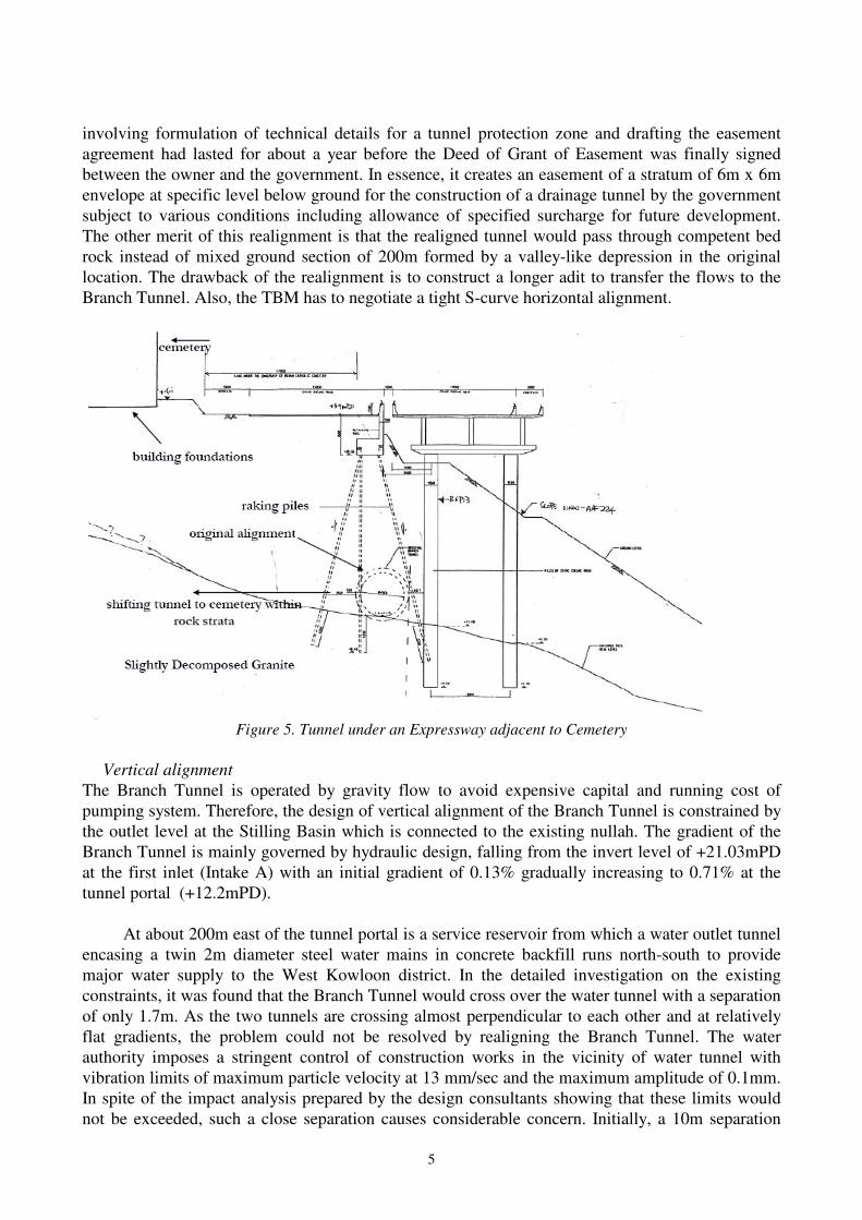
In the course of design review, we discovered rows of raking piles along approximately 200m stretch of tunnel route underneath Ching Cheung Road adjacent to a private cemetery. These raking piles were used to support a retaining wall for the cut-and-fill formation of the road (see Figure 5) built in the 1960s. By projecting the pile heads downwards, the Branch Tunnel would clash with these piles. It would not be feasible to detour the tunnel alignment to the southern side of the road which is scattered with industrial and residential buildings. Under this circumstance, the only viable option is to shift the tunnel alignment to the north into the cemetery. This would require negotiation with the owner of the cemetery for creation of a tunnel easement within the lot. The negotiation
Figure 4. Upper Hinterland of LCKTS
5
involving formulation of technical details for a tunnel protection zone and drafting the easement agreement had lasted for about a year before the Deed of Grant of Easement was finally signed between the owner and the government. In essence, it creates an easement of a stratum of 6m x 6m envelope at specific level below ground for the construction of a drainage tunnel by the government subject to various conditions including allowance of specified surcharge for future development. The other merit of this realignment is that the realigned tunnel would pass through competent bed rock instead of mixed ground section of 200m formed by a valley-like depression in the original location. The drawback of the realignment is to construct a longer adit to transfer the flows to the Branch Tunnel. Also, the TBM has to negotiate a tight S-curve horizontal alignment.
Figure 5. Tunnel under an Expressway adjacent to Cemetery
Vertical alignment
The Branch Tunnel is operated by gravity flow to avoid expensive capital and running cost of pumping system. Therefore, the design of vertical alignment of the Branch Tunnel is constrained by the outlet level at the Stilling Basin which is connected to the existing nullah. The gradient of the Branch Tunnel is mainly governed by hydraulic design, falling from the invert level of +21.03mPD at the first inlet (Intake A) with an initial gradient of 0.13% gradually increasing to 0.71% at the tunnel portal (+12.2mPD).
At about 200m east of the tunnel portal is a service reservoir from which a water outlet tunnel encasing a twin 2m diameter steel water mains in concrete backfill runs north-south to provide major water supply to the West Kowloon district. In the detailed investigation on the existing constraints, it was found that the Branch Tunnel would cross over the water tunnel with a separation of only 1.7m. As the two tunnels are crossing almost perpendicular to each other and at relatively flat gradients, the problem could not be resolved by realigning the Branch Tunnel. The water authority imposes a stringent control of construction works in the vicinity of water tunnel with vibration limits of maximum particle velocity at 13 mm/sec and the maximum amplitude of 0.1mm. In spite of the impact analysis prepared by the design consultants showing that these limits would not be exceeded, such a close separation causes considerable concern. Initially, a 10m separation

6
between the two tunnels was required by the water authority. Due to hydraulic requirement of the Branch Tunnel, such separation by raising the vertical alignment could not be achieved. It was finally agreed that a 5-m separation would be acceptable subject to checking of the impact assessment by an independent All Reservoir Panel Engineer and implementation of protection measures and monitoring during tunnel driving at this location. In this respect, specification was incorporated in the tender document to constrain the vibration induced by the TBM within a zone of 120m of the water tunnel and require continuous monitoring of vibration, deformation and settlement within the water tunnel. As an additional safety measure, the water supplies will be shut down during tunnel driving within the 120m zone to mitigate the consequence resulting from any damage of the water tunnel.
MAIN TUNNEL
Horizontal alignment
The flows intercepted in the upper hinterland are transferred via the Branch Tunnel by gravity to the Stilling Basin for discharge into the existing nullah, which was designed for conveying overflows from the Kowloon group of reservoirs. The nullah would not have the extra capacity to handle the combined flows from the Branch tunnel and the overflows from the reservoirs. The Stilling Basin together with a major new drainage system commencing at this location are thus required. To avoid problems associated with road opening and construction in busy urban areas, a tunnel system, i.e. the Main Tunnel is adopted. The closest point of discharge flows from the Stilling Basin via the Main Tunnel is Victoria Harbour. The horizontal alignment of the Main Tunnel is constrained by existing developments and private land. There is only a narrow north-south corridor available which essentially follows the existing twin box culverts and Route 8 Highway viaduct. In the original alignment, around 700m long of the Main Tunnel runs underneath an existing box culvert which is delineated as a drainage reserve within which the government has right to access and maintain the drainage system. The Main Tunnel would cross below three existing railway lines, namely, MTR Tsuen Wan line near the northern section, and West Rail and MTR Lantau and Airport Railway near the southern section. Abutting the route there are existing structures and buildings, in particular very close to a densely populated residential development, and foundations of highway viaducts.
Vertical Alignment
Given the constraints in this highly developed area with existing buildings, flyover, railway lines and piled foundations, it necessitates a relatively deep tunnel which would be fully surcharged under all flows, i.e. an inverted siphon. The flow of water is driven by sufficient hydraulic head (15m) at the inlet Shaft M1. The invert level of the Main Tunnel in the original scheme was set at -80mPD, with a view to providing sufficient cover of rockhead to avoid existing foundations. In the course of design review, the GI works revealed at some locations the presence of highly fracture zones. To mitigate the possible problem of ground settlement due to water table drawdown and to reduce the construction difficulty and uncertainty of constructing about 90m deep shafts under high elevated water pressures, in particular Shaft M2 located in reclaimed land adjacent to sea, the vertical alignment was raised to -40mPD. The change would facilitate the maintenance of the tunnel at a shallower level. The level could not be raised further due to the presence of existing railway lines and a planned express railway – Express Rail Link (XRL) which would cross over the Main Tunnel with a clearance of about 2m (see Figure 6). According to the programme, the Main Tunnel would be completed around one year ahead of the construction of two XRL TBM tunnels at this location. Interface issues are being co-ordinated between the two project teams, which involve the impacts on

7
the lining design and the completed Main Tunnel due to XRL advance works in the vicinity and driving the XRL tunnels by TBM. After raising the vertical alignment to -40mPD, it was found that about 600m of the twin cell box culverts along which the tunnel alignment runs underneath are supported by bored piles with founding levels down to –51mPD. These piles were used to support the box culvert constructed in newly reclaimed land. Under this circumstance, the horizontal alignment of the Main Tunnel was required to be revised to avoid these piles (see Figure 7). The revised alignment took a detour to the west side of the Route 8 Highway viaduct encroaching upon two government lots with potential developments before swinging back to the southern section of box culverts with no piled foundations. In the design of this alignment, due consideration was given to the adjacent pile foundations of Route 8 Highway viaduct, with founding levels ranging from -31mPD to -66mPD. To maintain minimum turning radius of the TBM of 200m for driving the tunnel between piles, the clearance would be as small as 2.5m. With the alignment shifted to the west, the risk of settlement at the densely populated residential development founded on friction piles was also reduced.
Figure 6. Clearance between XRL Tunnels and LCKTS Main Tunnel
Figure 7. Re-routing of Main Tunnel

8
REFERENCE DESIGN
This project adopts a design-and-build approach but the Employer retains the design responsibility of the following elements:
Alignment and gradients of tunnels and adits; Hydrualic design of the inlets, shafts and tunnels; and Site layouts for headworks, stilling basin, outfall and associated site formation works
Under a design-and-build contract, the contractor shall follow the Employer’s Requirements comprising a reference design which sets out critical and specific requirements such as minimum dimensions to be met in the detailed design. The minimum diameters required for the tunnels are governed by hydraulic requirements. The Branch Tunnel has to intercept a design flow of the hinterland with a 200-year return period storm. To meet this capacity of flow, a minimum 4.9m internal diameter is required. The Main Tunnel has to carry the combined flows of the Branch Tunnel and the overflows from the Kowloon group of reservoirs. In the original scheme, the diameter of the Main Tunnel to carry the combined flows was designed to be 6.4m. With the development of the Inter-Reservoir Transfer Scheme (IRTS), an integrated tunnel project which would transfer 75% of reservoir overflows to another reservoir, the diameter of the Main Tunnel can thus be reduced to 4.9m. The two integrated tunnel projects can achieve dual objectives of alleviating flooding and conservation of water resources. In addition, with the same diameter, i.e. 4.9m for both Branch Tunnel and Main Tunnel, there is a scope of using one TBM to construct the two tunnels.
Lining design
The Branch Tunnel will be excavated within competent rock. In theory, the tunnel is self-supporting and structural lining may not be required. To meet the hydraulic design requirement for a smooth tunnel wall and to control excessive groundwater inflow, the specification calls for a one-pass permanent segmental concrete lining. For the durability and strength requirements, grade 60 concrete with a design life of 120 years was specified for the lining in the reference design. The lining is an undrained design to achieve essentially “water tight” by bolted and gasketed concrete segments, with ground water infiltration rate limited to 1 litre/min/10m length of tunnel. For the Main Tunnel, to prevent ingress of ground water flow, the excavated tunnel is lined immediately with segmental lining as excavation advances by a closed mode TBM. The Branch Tunnel predominantly within bedrock can be lined with in-situ concrete or segmental lining. In the case of in-situ lining, the excavated tunnel would be left unlined for a long time and would require temporary support. From cost and programme considerations, the in-situ lining was considered less favourable. Another important consideration was that in-situ lining would not be compatible with the closed mode TBM for the Main Tunnel. The option to use one TBM for constructing two tunnels with different types of lining would be technically complicated. This factor coupled with other considerations on maintenance and hydraulic performance has led to the decision of adopting segmental lining for both tunnels.
CONSTRUCTION CONSIDERATIONS
The two tunnels have very different geological characteristics. The Branch Tunnel passes through predominately very strong to extremely strong abrasive granite intercepting a number of faults and shear zones. The tunnel can be excavated by TBM or by drill-and-blast method. Open face TBM construction, using either open beam, single shield or double shield TBM, supported by pre-

9
excavation grouting was the method specified in the tender document in considering that drill-and-blast method would have potentially adverse effects on sensitive slopes and structures along the route of the tunnel. The Main Tunnel starts with full face strong to extremely strong granite in the northern section and enters into approximately 700m soft/mixed ground with corestones. The section through water bearing mixed/soil ground will be subject to hydrostatic pressure of around 4.2 bar. A closed face TBM construction using either slurry shield or earth pressure balanced shield TBM supported with an undrained permanent pre-cast tunnel lining is necessary. Cutterhead should be fitted with disc cutters across the face to provide for full face rock cutting. The discs shall have a loading capacity capable of excavating the materials, as described in the Geotechnical Baseline Report (GBR), especially the strong and abrasive granite with average UCS of about 200 MPa. The choice of specific type of TBM was left to the contractor in the tender proposal based on, among other considerations, face stability, ground loss, ground water control, programme and control of settlement. It was considered that it might be possible to excavate the two tunnels of a total length 3.7km using one TBM within the 44-month contract period. Therefore, option was allowed in the tender document for the contractor to propose one or two TBMs to complete the job. It is possible that a dual mode TBM can be used to excavate both tunnels by operating in open or closed mode, depending on different ground conditions. The direction of TBM launching and the sequence of driving the two tunnels will also be determined by the contractor.
Cutterhead Intervention
Due to the variability of the ground a high incidence of disc cutter and cutting tool damage is envisaged. Cutterhead intervention for inspection, maintenance, and repair may require ground treatment and the use of compressed air to achieve a safe working environment. It may be necessary to abort interventions due to unstable face conditions and advance the TBM to better ground. Due to high ground water pressure in the compressed air intervention, it may be necessary to apply an air pressure exceeding 50psi i.e. 3.45 bar for which approval of the Commissioner for Labour is required. There has been no precedent case in Hong Kong for works in compressed air at pressure at this limit. Detailed submission based on overseas experience will be required. As contingency measures, to avoid the use of compressed air exceeding 3.5 bar, the contractor could plan the interventions ahead and carry out ground treatment from surface at chosen locations along the tunnel route taking into account the predicted ground conditions, proximity to sensitive structures, expected disc cutter and tool wear. It was considered possible to use materials like microfine cement grout, sodium silicate grout or colloidal grout to reduce the ground water pressure to below 3.5 bar. Jet-grouted blocks to be created prior to the arrival of the TBM can provide a “safe haven” for manned intervention to carry out cutterhead maintenance works. This could increase the available working time and decrease worker’s exposure to the high compressed air pressure. It was considered that grout trial should be carried out in advance to test the effectiveness of the grouting. Unplanned interventions may be required during the tunnel driving due to a number of factors e.g. unforeseen geological conditions or damaged cutterhead discs or tools. To facilitate unplanned interventions, grouting can be carried out from within the TBM to reduce the ground water pressure. It has been specified that the TBM must equip with at least 12 grout ports in the TBM shield and drilling rigs to perform grouting (see Figure 8).

10
Figure 8. Grouting from TBM
Shaft and Adit Construction
Five numbers of adit with internal diameter of 3m and a total length of 270m will be constructed by drill-and-blast method. The launching shaft for the TBM (at Shaft M1) together with the launching

11
chamber will also be excavated by drill-and-blast. The outlet Shaft M2 adjacent to the sea with soil stratum down to -60mPD will be constructed by using slurry diaphragm walling acting as temporary and permanent lining. The six drop shafts of diameters ranging from 3m to 3.7m would mainly be constructed with two different techniques. The soil portion of the shaft is constructed by conventional top-down excavation method using temporary earth lateral supporting system such as steel sheet pile or pipe pile wall to be keyed into the rockhead. Further excavation below rockhead is to be carried out by drill-and-blast to reach the bottom of the shaft. The launching chamber for the Branch Tunnel is located below Ching Cheung Road with shallow cover of overburden soil. In view of the launching chamber being directly below a major highway and close to slopes with failure history, blasting is not permitted. It will be excavated by mechanical means supported by shotcrete and lattice girders. Raise boring for the excavation of shafts is an alternative to the drill-and-blast method, where site conditions allow. However, this method would require the completion of adits and the connection Branch Tunnel in advance and would therefore impose programme and access constraints to the contractor.
RISK MANAGEMENT
Risk management is a key element in managing contract nowadays especially tunnelling works which has been classified as high risk by the insurance industry.
A Code of Practice for Risk Management of Tunnel Works (January 2006) has been prepared and published by The International Tunnelling Insurance Group (TITG) for promoting and securing best practice for the minimization and management of risks associated with the design and construction of tunnels, caverns, shafts and associated underground structure. It also sets out practice for the identification of risks, their allocation between the parties to a contract and contract insurers, and the management and control of risks through the use of Risk Assessments and Risk Registers.
Risk Assessments required at each stage of a project shall be summarized in appropriate Risk Registers. Risk Registers shall clearly indicate the party responsible for the control and hence management of an identified risk, as well as contingency measures available for the mitigation of the risk. Risk Registers shall be “live” documents that are continually reviewed and revised as appropriate and available for scrutiny at any time. Insurance should not be considered as a contingency or mitigation measure in risk assessment for tunnel works.
For the LCKTS, to improve the identification and management of risks in ground conditions, we have provided a comprehensive risk management plan at the design stage and carried out sufficient and adequate ground investigation works. In addition, Risk Registers have been maintained during the design stage and carried through to the construction stage.
CONTRACT PROCUREMENT
Allocation of risk in construction is one of the principal factors for choosing appropriate contract form. This provides an incentive to designing conditions of contract which improves the motivation of good management. Conditions of contract is a key document setting out the terms and conditions of a contract to ensure more effective teamwork, planning and foresighted decision making. Currently, Hong Kong is using the Conditions of Contract basically modelled from the Conditions of Contract of the Institution of Civil Engineers, UK. In deciding the contract procurement for the LCKTS, we have focused on the possible use of the New Engineering Contract (NEC) and the common Norwegian tunnelling contract form. The NEC advocates a new legal
12
framework of project management procedures in stimulating good management, flexibility and simplicity, and requests that the Employer, the Contractor and the Project Manager and the Supervisor shall act in the spirit of mutual trust and co-operation for equitable risk sharing. Whereas Norwegian contracts addresses two main elements of risk:
Ground conditions – The project owner is responsible for the ground conditions including results from site investigations.
Performance – The contractor is responsible for the efficient execution of the works. The
works shall be executed according to technical specifications. The contractor is reimbursed according to tendered unit rates for the work accurately completed. Construction time frame is adjusted based on preset standard capacities for different work activities.
Although each contract form has its own merits, their drawbacks are:
As the NEC form has not been widely practiced in the Hong Kong’s public works projects, it will expose the Government to significant contractual uncertainties in the implementation of this mega tunnel project.
For the Norwegian tunneling contracts, time is measured using the norm set by standard
capacities, which are built up based on long term statistical data of tunneling work in Norway. These standard capacities are predominated for drill-and-blast tunnels which are not applicable to the TBM tunnels dominated for the LCKTS, which will have characteristics completely different from that of a hard rock drill-and-blast tunnel. Moreover, the Norwegian bills of quantities and specifications are all for drill-and-blast tunnels which are not applicable to a TBM tunnel contract.
After considering the risks involved, design-and-build Contract but including the Engineer’s design elements and Contractor’s design elements is adopted for the LCKTS. The HKSAR General Conditions of Contract for design-and-build Contracts with a ‘Differing Site Conditions” clause together with re-measurement on certain elements for achieving a balanced equitable risk sharing requirement for the project are used.
The tenderers for the LCKTS Contract are pre-qualified to ensure their capability on the works. We have also required the tenderers during the pre-qualification stage to submit preliminary method statement for key activities to demonstrate their appreciation of the construction difficulties and to demonstrate their understanding of the constructability of the works.
GEOTECHNICAL BASELINE REPORT DEVELOPMENT
In tendering for a tunnel contract, it is important that the subsurface conditions that tenderers should anticipate when preparing for their tenders are described. Information or estimation of the subsurface conditions has been presented in form of a Geotechnical Data Report and Geotechnical Baseline Report.
Geotechnical Data Report (GDR)
The GDR is a document developed by the designer containing the factual information that has been gathered during the investigation and design stages of a project. As the Employer have been developing the project for years, it would be surely beneficial for the tenderers to access all relevant

13
information pertaining to the project. The practice now is that relevant information specific to the project which is possessed by the Employer that is considered relevant to the tendering should be made known to the tenderers.
Geotechnical Baseline Report (GBR)
The GBR establishes a contractual understanding of the subsurface site conditions, referred to as the baseline. It sets out conditions based on which the tenderers are expected to submit their tenders. The baseline statements in the GBR are therefore expressed as contractual representations of the anticipated geotechnical conditions. It is not a warranty of the actual ground conditions that the Contractor will encounter on site during construction.
Benefits of Adopting GBR
The risk management approach in design and documentation is to reduce and control construction and contractual risks. The GBR enhances the traditional contractual risk problem by including a contractual set of parameters, defining and settling common baselines for all the tenderers to price instead of arguing whether the underground risks/obstructions are foreseeable under the contact whenever disruptions happen during the construction stage.
In order to achieve a more equitable risk sharing mechanism for subsurface conditions, the
LCKTS adopts the use of GBR including the following:
The GBR itself will form part of the contract document and takes precedence over all other
geotechnical and geological interpretative and data reports and documents which have been produced during the course of the project.
The inclusion of a Differing Site Conditions (DSC) clause in the Conditions of Contract to
effect the equitable sharing of risks due to ground conditions. Risks associated with conditions consistent with or less adverse than the baseline are allocated to the Contractor, and risks for conditions significantly more adverse than the baselines are allocated to the Employer.
With the use of a GBR and DSC, there will be a contractual baseline to assess the validity of
the principle of a claim. The GBR if properly drafted should limit the valid reasons to claim and reduce the potential for frivolous claims. The focus of the claim assessment will be on quantum for which the Engineer can value based on contract rates.
Use of re-measurement for items with uncertain quantities which cannot casually be baselined
and allow extension of time if the ground conditions are worse than the GBR to further enhance the risk sharing mechanism. In this respect, ground water inflow was not baselined in the GBR. Instead, the GBR makes reference to the relevant specification that pre-excavation grouting subject to re-measurement according to the actual grout quantities required to stop unacceptable groundwater inflow from probe holes as specified in the Contract.
CONCLUSION
The Lai Chi Kok Transfer Scheme has presented a huge challenge to the project team in respect of alignment design and resolving constraints with stakeholders for constructing drainage tunnels in dense urban areas. Through the concerted effort of the project team and design consultants – Maunsell Consultants Asia Limited, the contract was successfully awarded to Leighton – John Holland Joint Venture in November 2008 at a contract sum of US$170 million for completion in end 2012. TBM and drill-and-blast tunneling works are expected to be carried out in early 2010.

14
Close collaboration among the client, the contractor, and the site supervision team is required to resolve challenging issues including regulatory, geotechnical and stakeholders constraints.
REFERENCES Drainage Services Department Hong Kong SAR Government (2008), Geotechnical Baseline Report, Design and
Construction of Lai Chi Kok Transfer Scheme, prepared by Maunsell Consultants Asia Limited. Drainage Services Department Hong Kong SAR Government (2008), Geotechnical Data Report, Design and
Construction of Lai Chi Kok Transfer Scheme, prepared by Maunsell Consultants Asia Limited. Essex, R.J. Editor (2007), Geotechnical Baseline Reports for Underground Construction, Suggested Guidelines, The Technical Committee on Geotechnical Reports of the Underground Technology Research Council : American Society of Civil Engineers. The International Tunnelling Insurance Group (2006), A Code of Practice for Risk Management of Tunnel Works.
The British Tunnelling Society (2003), The Joint Code of Practice for Risk Management of Tunnel Works in the UK.