design and numerical analysis of … and numerical analysis of processes in siloxane vapor driven...
TRANSCRIPT
Paper ID: 44, Page 1
3rd
International Seminar on ORC Power Systems, October 12-14, 2015, Brussels, Belgium
DESIGN AND NUMERICAL ANALYSIS OF PROCESSES IN
SILOXANE VAPOR DRIVEN TURBINE
A. Sebelev*1, R. Scharf
2, N. Zabelin
1, M. Smirnov
1
1Peter the Great St. Petersburg Polytechnic University (SPbPU),
Department “Turbines, Hydro machines and aero-engines”
St. Petersburg, Russia; 2Leibniz Universität Hannover,
Institut für Kraftwerkstechnik und Wärmeübertragung
Hannover, Germany
e-mail: [email protected]
ABSTRACT
The problem of decreasing of fossil fuel consumption and energy efficiency is one of today’s major
conceptions in the field of energy economics. Waste heat recovery is one of the promising solutions
for this problem. One of the ways to increase efficiency of the waste heat recovery process is using
siloxanes as working fluids for organic Rankine cycles (ORC).
SPbPU scientists have analyzed peculiarities of the steady-state expansion process in the siloxane
vapor driven turbine. The design of the nozzle and the blade wheel of the turbine is supersonic due to
the low speed of sound of siloxanes. Initial parameters of siloxane were subcritical; a pressure ratio of
the turbine was 25. Progressive steps of the initial temperature, pressure ratio and rotational velocity
were used to obtain convergence of the solution process. The changings of positions of the nozzle and
blade wheel critical sections were established. The details of the supersonic vortices interaction in the
blade wheel flow range were analyzed.
The efficiency and power output of the investigated turbine stage were estimated as 0.699 and
309.1 kW, respectively.
1. INTRODUCTION
Waste heat recovery is one of the promising solutions to increase efficiency of different plants and
industrial processes (Larjola (1995), Vescovo (2009)). The highest volume of waste heat resources
takes place at different thermal power plants, cement, metallurgical and chemical productions. In
Russia it is also the gas transport industry. The estimation of waste heat thermal power at the all gas
compressor stations of “Gazprom” is 87.9 GW (Lykov et al. (2013)). Rough estimations of waste heat
thermal power at different productions in Russia, made on the base of Key World Energy Statistics
(2014), are: 3.9 GW at the all cement production plants, 2.8 GW at the all metallurgical production
plants and 1.9 GW at the all chemical production plants. In the other words, all this waste heat may be
turned to 14.5 GW of electrical power by the most conservative estimate.
In most cases using of organic Rankine cycles (ORC) for recovery plants provides higher efficiency
of the recovery plants in comparison with water steam Rankine cycle due to low temperature levels of
the waste heat streams (Larjola (1995), Hung et al. (1997), Vescovo (2009)). The average temperature
level of the waste heat streams in the whole Russian gas transport system is 390ºC by the estimation
of Lykov et al. (2013). The average temperature level of the waste heat streams at other productions
in Russia varies from 150ºC to 350ºC. One of the most important questions in the recovery plant
designing is the choosing of a working fluid. Nowadays the aspects of using of various hydrocarbons,
freons and alcohols in ORC are widely researched by different authors (Iqbal et al. (1977), Hung et al.
(1997), Shuster et al. (2010), Gao et al. (2012)). Modern requirements for environment safety
determine ozone depletion potential (ODP) and global warming potential (GWP) as main criteria for
Paper ID: 44, Page 2
3rd
International Seminar on ORC Power Systems, October 12-14, 2015, Brussels, Belgium
choosing of a working fluid. It was shown that in this case the most promising alternatives to different
hydrocarbons, freons and alcohols are zeotropic mixtures and siloxanes (Heberle et al. (2012), Chys et
al. (2012), Weith et al. (2014)). The aspects of using of siloxanes in ORC were investigated by Lai et
al. (2011), Fernandez et al. (2011), Uusitalo et al. (2013). It was shown that in this case the efficiency
of ORC may be increased up to 23 – 25%.
The turbines for organic working fluids have essential differences in details of the expansion process
in comparison with typical gas and steam turbines. The special supersonic design is required for such
turbines due to low speed of sound of different organic working fluids. The aspects of designing of
the ORC driven turbines were outlined by different authors. Yamamoto et al. (2001) designed and
tested R-123 centripetal turbine; Kang (2012) designed and tested R-245fa radial-inflow turbine;
Casati et al. (2014) described designing method of the ORC centrifugal microturbines. Guardone et
al. (2013) described the influence of molecular complexity on nozzle design.
Despite the high volume of investigations in the area of organic working fluids expansions the
peculiarities of siloxanes behavior during the expansion process still haven’t been outlined. Thus, the
scope of the present paper is to investigate the siloxane expansion process and to outline its
peculiarities.
2. INVESTIGATION OBJECT
2.1. Initial parameters of the expansion process
Hexametyldisiloxane (MM) was chosen as working fluid for the expansion process. The initial
pressure p0 was set as 1 MPa. The initial temperature T0 was set as a vapor saturation temperature at
chosen initial pressure. The turbine pressure ratio has been chosen as 25 to provide the required
turbine enthalpy drop upon the condition of 300 kW power output of the turbine stage. Trans- and
supercritical initial parameters were not considered.
Positive slope of MM vapor saturation curve provides inability of intersection between expansion
process curve and two-phase region as shown in figure 1. It means that there is no possibility of
droplet formation in the turbine stage.
Figure 1: T-s diagram of the expansion process
2.2. The turbine
A single-stage double-flow axial turbine was chosen as the expander machine. The choice of the
double-flow design was made due to high axial forces acting on the turbine rotor. The subsonic part of
the nozzle was designed according to Vitoshinski profile. The supersonic part of the nozzle was
designed using the SPbPU high pitch-chord ratio design. The main features of the high pitch-chord
ratio design, described in details by Rassokhin (2004), are:
small angles α1 (3..5º) and β1 (8..14º);
320,00
370,00
420,00
470,00
520,00
570,00
0,20 0,40 0,60 0,80 1,00
Turbine
Regenerator
(hot side)Condenser
Preheater
Evaporator
s, kJ/kg
T, K

Paper ID: 44, Page 3
3rd
International Seminar on ORC Power Systems, October 12-14, 2015, Brussels, Belgium
high blade wheel flow turning angle (Ω = 151..164º);
high pitch-chord ratio for the nozzle and blade wheel blades (tN/bN > 4, tBW/bBW > 1.1);
high enthalpy drops at one turbine stage (up to 800 kJ/kg).
The supersonic blade profile C9022B was chosen for the blade wheel. This blade profile was
described in details by Dejch et al. (1965). The reason to use blade profile with thick leading edge is
strong changing of MM properties with relation to thermodynamic parameters. The design of the
nozzle and blade wheel is supersonic due to low MM speed of sound. Involutions of the nozzle and
blade wheel at the mean diameter are shown in figure 2. The blade wheel of the turbine has a tip
shroud. The main geometric parameters of the single-flow turbine stage are given in table 1.
a) b)
Figure 2: Involutions of the nozzle (a) and blade wheel (b) at the mean diameter
Table 1: The main geometric parameters of the one-flow turbine stage
Parameter Dimensions Value Parameter Dimensions Value
Dm mm 380 α1 deg. 7.00
n rev/min 12000 ΔLax mm 7.00
H0 kJ/kg 66.26 ΔLtc mm 0.30
G kg/s 6.86 β1 deg. 90.00
Cax/u - 1.52 Z2 - 55
ε - 0.97 l2 mm 24.75
Z1 - 7 β2* deg. 30.00
l1 mm 18.95 Ω deg. 60.00
3. NUMERICAL SIMULATION METHOD
The SPbPU method for numerical simulation of processes in supersonic turbines, described by
Zabelin et al. (2013), was used. ANSYS CFX was used to provide the numerical simulation.
The original relation between the number of nozzles and number of working blades is 7/55. The
relation 1/8 and periodic boundary conditions were used in the computational model. This assumption
is correct to be used with Frozen Rotor interface between the nozzle and blade wheel areas because
the relation between connecting areas in this case is 1:1.018. The modeling of blade wheel tip shroud
was also considered in numerical model in assumption of rotating motion of tip shroud domain. The
computational model of the single-flow turbine stage is presented in figure 3.

Paper ID: 44, Page 4
3rd
International Seminar on ORC Power Systems, October 12-14, 2015, Brussels, Belgium
Figure 3: Computational model of the single-flow turbine stage
High-Reynolds version of the k-ω SST turbulence model was used. Steady-state Frozen rotor
interface between the nozzle and blade wheel areas was used to model rotor-stator interaction. Flow
parameters of the turbine stage were obtained by averaging of their values for 4 positions of blade
wheel relatively to the nozzle in the range of blade wheel pitch angle.
Aungier Redlich Kwong real gas equation of state was used to model thermodynamic properties of
MM during the expansion process. The main parameters need to be specified are: molar mass, critical
temperature and pressure, acentric factor and boiling temperature. Zero pressure polynomial
coefficients were obtained with using REFPROP databases to evaluate specific heat capacity of MM.
Kinetic Theory models were used to model transport properties of MM. Rigid Non Interacting Sphere
model was used to model MM dynamic viscosity behavior.
Total parameters at inlet (p0 = 1 MPa, T0 = 477.1 K) and static pressure at outlet (p0 = 0.04 MPa) were
specified as boundary conditions in computational model. Progressive steps of the boundary
conditions were used to obtain convergence of the solution process. The iteration steps between the
changings of boundary conditions were different to decrease their negative influence on the solution
process. Monitoring of the RMS residuals, imbalances and turbine efficiency and power output were
used to control convergence of the solution process. The criteria of the convergent solution in present
research were:
drop of the RMS residuals more than 102;
imbalances less than 0.5%;
fluctuation of the turbine efficiency and power output less than 5%.
Three different types of computational domains discretization were compared to obtain grid
independent solution. The results of the grid independency study are presented in table 2.
Table 2: The results of the grid independency study
Grid type
1 nozzle
sector,
millions
of nodes
8 blade wheel
sectors,
millions of
nodes
8 tip shroud
sectors,
millions of
nodes
Difference in the
turbine efficiency
with the previous
grid, %
Difference in the
turbine power
output with the
previous grid, %
Coarse 0.68 3.21 3.15 - -
Medium 1.15 6.85 4.26 10.2 15.4
Fine 1.98 10.64 5.32 4.2 4.8

Paper ID: 44, Page 5
3rd
International Seminar on ORC Power Systems, October 12-14, 2015, Brussels, Belgium
The medium grid was used in further calculations. The grid structure is presented in figure 4.
Figure 4: The grid structure
4. DISCUSSION OF THE RESULTS
The values of the calculated thermodynamic and transport properties were compared with the values
obtained with using REFPROP databases to estimate tolerance of the obtained results. Maximum
deviation between CFX and REFPROP results was less than 5% for specific heat capacity and
dynamic viscosity. It is noteworthy that isentropic exponent of MM has a strong nonlinear
dependence on temperature and pressure in superheated vapor area as shown in figure 5a. In this case
it is incorrect to use constant isentropic exponent in preliminary turbine calculations. Rough boundary
in figure 5a is a consequence of discrete steps of temperature and pressure.
a) b)
Figure 5: MM isentropic exponent dependence on temperature and pressure in superheated vapor area (a) and
varying of the nozzle outlet angle outbound of the nozzle (b)
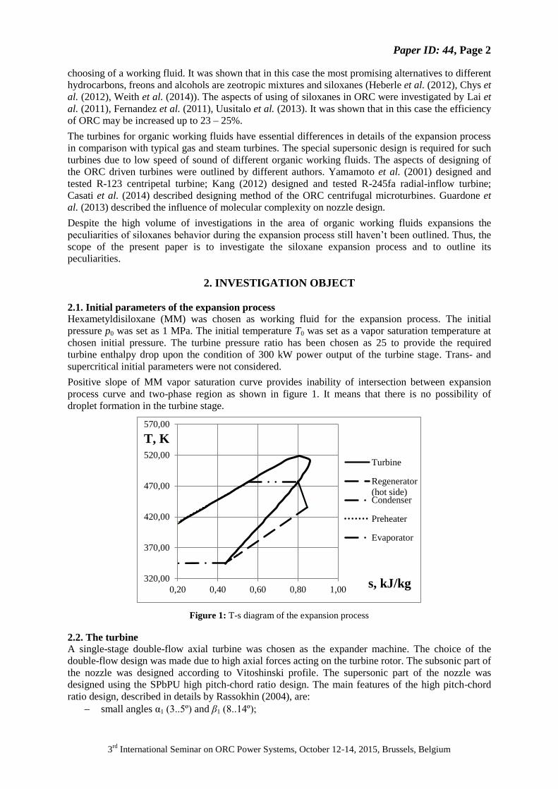
The analysis of Mach number field in the nozzle (figure 6) shows that the flow in the critical section is
not fully supersonic. It can be seen in details in figure 7. Physically, it means that the position of real
critical section changed to the downstream direction in comparison with its design position. This
420
430
439
449
458
468
477,2
0,040,20,360,520,680,841
p, МПа
1,18-1,21
1,15-1,18
1,12-1,15
1,09-1,12
1,06-1,09
1,03-1,06
1-1,03
T, K
k
9,00
9,50
10,00
10,50
11,00
11,50
12,00
0,00 2,00 4,00 6,00
α1, deg.
ΔLax, mm
Paper ID: 44, Page 6
3rd
International Seminar on ORC Power Systems, October 12-14, 2015, Brussels, Belgium
phenomenon was established by Reichert and Simon (1997). This fact means that the theoretical mass
flow rate through the supersonic nozzle, defined as:
,1
2 1
1
0
0
k
k
cst
kR
k
T
SpG (1)
should be based on the cross-sectional area of the real critical section. Additionally, the velocity
profile near the critical section is highly distorted towards to the straight nozzle wall. This is a
consequence of the non-symmetric shape of the nozzle and was also outlined by Reichert and Simon
(1997). The same situation takes place near the blade wheel critical section.
Figure 6: Mach number field in the turbine stage at the mean diameter
Figure 7: Velocity profiles near the nozzle critical section at the mean diameter
The oblique shock wave from the nozzle reflects from the nozzle wall and then impinges on the
leading edge of the blades. This leads to the appearing of the local zones with high Mach number (up
to 2.5 in stationary frame) at the blades leading edges. Such flow behavior is typical for axial
supersonic turbines and was described in details by Kirillov (1972) and Traupel (1977). It should be
outlined that the nozzle outlet angle, defined as:
,2
11
N
zm
M
cDGarctg (2)
0,70
0,80
0,90
1,00
1,10
1,20
0,0092 0,0142 0,0192
Mach
nu
mb
er
Coordinate, m
0.5 mm
before critical
section
critical
section
0.5 mm after
critical
section
Paper ID: 44, Page 7
3rd
International Seminar on ORC Power Systems, October 12-14, 2015, Brussels, Belgium
has a decreasing value outbound of the nozzle as shown in figure 5b. Zabelin et al. (2013) showed
that this phenomenon is a consequence of the blade wheel influence on the nozzle in trans- and
supersonic turbines. The nozzle torque in equation (2) was calculated directly in CFD-Post.
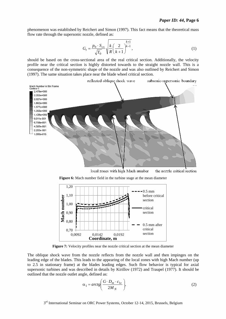
The analysis of the flow structure in the blade wheel shows that double vortex structure appears at the
blade wheel inlet as shown in figure 8. It is a consequence of complex phenomena which take place at
the edges of the nozzles active flow sectors. These phenomena related to the flow separation and were
described by Natalevich (1979). The hub vortex rotates clockwise and rests against the blade wheel
hub. The shroud vortex has a counterclockwise rotation and rests against the blade wheel shroud
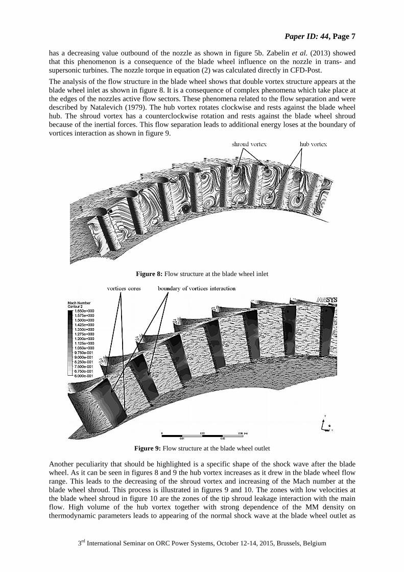
because of the inertial forces. This flow separation leads to additional energy loses at the boundary of
vortices interaction as shown in figure 9.
Figure 8: Flow structure at the blade wheel inlet
Figure 9: Flow structure at the blade wheel outlet
Another peculiarity that should be highlighted is a specific shape of the shock wave after the blade
wheel. As it can be seen in figures 8 and 9 the hub vortex increases as it drew in the blade wheel flow
range. This leads to the decreasing of the shroud vortex and increasing of the Mach number at the
blade wheel shroud. This process is illustrated in figures 9 and 10. The zones with low velocities at
the blade wheel shroud in figure 10 are the zones of the tip shroud leakage interaction with the main
flow. High volume of the hub vortex together with strong dependence of the MM density on
thermodynamic parameters leads to appearing of the normal shock wave at the blade wheel outlet as
Paper ID: 44, Page 8
3rd
International Seminar on ORC Power Systems, October 12-14, 2015, Brussels, Belgium
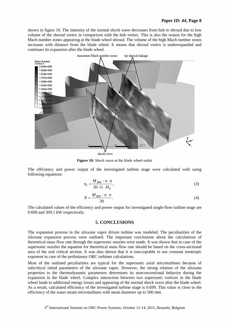
shown in figure 10. The intensity of the normal shock wave decreases from hub to shroud due to low
volume of the shroud vortex in comparison with the hub vortex. This is also the reason for the high
Mach number zones appearing at the blade wheel shroud. The volume of the high Mach number zones
increases with distance from the blade wheel. It means that shroud vortex is underexpanded and
continues its expansion after the blade wheel.
Figure 10: Shock wave at the blade wheel outlet
The efficiency and power output of the investigated turbine stage were calculated with using
following equations:
,30 0HG
nM BWi
(3)
.30
nMN BW (4)
The calculated values of the efficiency and power output for investigated single-flow turbine stage are
0.699 and 309.1 kW respectively.
5. CONCLUSIONS
The expansion process in the siloxane vapor driven turbine was modeled. The peculiarities of the
siloxane expansion process were outlined. The important conclusions about the calculations of
theoretical mass flow rate through the supersonic nozzles were made. It was shown that in case of the
supersonic nozzles the equation for theoretical mass flow rate should be based on the cross-sectional
area of the real critical section. It was also shown that it is inacceptable to use constant isentropic
exponent in case of the preliminary ORC turbines calculations.
Most of the outlined peculiarities are typical for the supersonic axial microturbines because of
subcritical initial parameters of the siloxane vapor. However, the strong relation of the siloxane
properties to the thermodynamic parameters determines its nonconventional behavior during the
expansion in the blade wheel. Complex interaction between two supersonic vortices in the blade
wheel leads to additional energy losses and appearing of the normal shock wave after the blade wheel.
As a result, calculated efficiency of the investigated turbine stage is 0.699. This value is close to the
efficiency of the water steam microturbines with mean diameter up to 500 mm.

Paper ID: 44, Page 9
3rd
International Seminar on ORC Power Systems, October 12-14, 2015, Brussels, Belgium
NOMENCLATURE
GW Gigawatt
GWP Global Warming Potential
kW Kilowatt
MM Hexametyldisiloxane
ODP Ozone Depletion Potential
ORC Organic Rankine Cycle
SPbPU Peter the Great St. Petersburg Polytechnic University
Cax/u stage load coefficient
c1z axial component of velocity at the nozzle outlet m/s
Dm mean diameter m
G mass flow rate kg/s
H0 isentropic enthalpy drop kJ/kg
k isentropic exponent
l1 nozzle height mm
l2 blade height mm
M torque N·m
n rotational speed rev/min
p0 nozzle inlet pressure MPa
p2 blade wheel outlet pressure MPa
R individual gas constant J/(kg·K)
S cross-sectional area m2
T0 nozzle inlet temperature K
Z1 number of nozzles
Z2 number of blades
α1 nozzle outlet angle deg.
β1 blade wheel inlet angle in relative frame deg.
β2* blade wheel outlet angle in relative frame deg.
ΔL clearance value mm
ε partial admission ratio
Subscript
BW blade wheel
N nozzle
ax axial
cs critical section
i internal
t theoretical
tc tip clearance
REFERENCES
[1] Casati, E., Vitale, S., Pini, M., Persico, G., Colonna, P., 2014, Centrifugal turbines for mini-
organic Rankine cycle power systems, Journal of Engineering for Gas Turbines and Power,
vol. 136, 122607.
[2] Chys, M., van den Broek, M., Vanslambrouck, B., De Paepe, M., 2012, Potential of zeotropic
mixtures as working fluids in organic Rankine cycles, Energy, vol. 44, pp. 623 – 632.
[3] Dejch, E.M., Filipov, A.G., Lazariev, J.L., 1965, Atlas profilej reshetok osevyh turbin,
Mashinostroyenie, Moscow, 96p.
[4] Fernandez, F.J., Prieto, M.M., Suarez, I., 2011, Thermodynamic analysis of high-temperature
regenerative organic Rankine cycles using siloxanes as working fluids, Energy, vol. 36, pp.
5239 – 5249.
Paper ID: 44, Page 10
3rd
International Seminar on ORC Power Systems, October 12-14, 2015, Brussels, Belgium
[5] Gao, H., Liu, Ch., He, Ch., Xu, Xi., Wu, Sh., Li, Y., 2012, Performance Analysis and
Working Fluid Selection of a supercritical Organic Rankine Cycle for low grade waste heat
recovery, Energies, vol. 5, pp. 3233 – 3247.
[6] Guardone, A., Spinelli, A., Dossena, V., 2013, Influence of molecular complexity on nozzle
design for an organic vapor wind tunnel, Journal of Engineering for Gas Turbines and Power,
vol. 135, 042307.
[7] Heberle, F., Preißinger, M., Brüggemann, D., 2012, Zeotropic mixtures as working fluids in
Organic Rankine Cycles for low-enthalpy geothermal resources, Renewable Energy, vol. 37,
pp. 364 – 370.
[8] Hung, T.C., Shai, T.Y., Wang, S.K., 1997, A review of Organic Rankine Cycles (ORCs) for
the recovery of low-grade waste heat, Energy, vol. 22, pp. 661 – 667.
[9] Iqbal, K.Z., Fish, L.W., Starling, K.E., 1977, Isobutane geothermal binary cycle sensitivity
analysis, Proceedings Oklahoma Academic Science, The University of Oklahoma,
pp. 131 – 137.
[10] Kang, S.H., Design and experimental study of ORC (organic Rankine cycle) and radial
turbine using R245fa working fluid, 2012, Energy, vol. 41, pp. 514 – 524.
[11] Key World Energy Statistics, International Energy Agency, 2014.
[12] Kirillov, I.I., 1972, Teorija turbomashin, Mashinostroyenie, Leningrad, 533p.
[13] Lai, N.A., Wendland, M., Fischer, J., 2011, Working fluids for high-temperature organic
Rankine cycles, Energy, vol. 36, pp. 199 – 211.
[14] Larjola, J., 1995, Electricity from industrial waste heat using high-speed organic Rankine
cycle (ORC), International journal of production economics, vol. 41, pp. 227 – 235.
[15] Lykov, A.V., Zabelin, N.A., Rassokhin, V.A., 2013, Estimation of waste heat resources in
Russian unified system of gas supply, St. Petersburg State Polytechnical University Journal,
vol. 183 (4), pp. 136–145.
[16] Natalevich, A.S., 1979, Vozdushnye mikroturbiny, Mashinostroyenie, Moscow, 192p.
[17] Rassokhin, V.A., 2004, Turbiny konstrukcii LPI: preimushhestva, harakteristiki, opyt
razrabotki i primenenie, St. Petersburg State Polytechnical University Journal, vol. 491, pp.
152 – 161.
[18] Reichert, A.W., Simon, H., 1997, Design and flow field calculations for transonic and
supersonic radial inflow turbine guide vanes, Journal of turbomachinery, vol. 119 (1), pp. 103
– 113.
[19] Shuster, A., Karellas, S., Aumann, R., 2010, Efficiency optimization potential in supercritical
Organic Rankine Cycles, Energy, vol. 35, pp. 1033 – 1039.
[20] Traupel, W., 1977, Thermische Turbomaschinen, 3. Aufl., Springer, Berlin, 579p.
[21] Uusitalo, A., Turunen-Saaresti, T., Honkatukia, J., Colonna, P., Larjola, J., 2013, Siloxanes as
working fluids for mni-ORC systems based on high-speed turbogenerator technology, Journal
of Engineering for Gas Turbines and Power, vol. 135, 042305.
[22] Vescovo, R., 2009, ORC recovering industrial heat, Cogeneration and On-Site Power
Production, vol. 2, pp. 53 – 57.
[23] Weith, T., Heberle, F., Preißinger, M., Brüggemann, D., 2014, Performance of siloxane
mixtures in a high-temperature Organic Rankine Cycle considering the heat transfer
characteristics during evaporation, Energies, vol. 7, pp. 5548 – 5565.
[24] Yamamoto, T., Furuhata, T., Arai, N., Mori, K., 2001, Design and testing of the organic
Rankine cycle, Energy, vol. 26, pp. 239 – 251.
[25] Zabelin, N.A., Rakov, G.L., Rassokhin, V.A., Sebelev, A.A., Smirnov, M.V., 2013,
Investigation of fluid flow highlights in low flow-rated LPI turbine stages, St. Petersburg
State Polytechnical University Journal, vol. 166 (1), pp. 45–53.