design and manufacturing of dimensionally...
TRANSCRIPT

DESIGN AND MANUFACTURING OF DIMENSIONALLY CONTROLLED
GRAPHENE BASED HYBRID STRUCTURES
BY CORE-SHELL ELECTROSPINNING
FOR ENERGY STORAGE SYSTEMS
by
LEILA HAGHIGHI POUDEH
Submitted to the Graduate School of Engineering and Natural Sciences
in partial fulfilment of the requirements for the degree of
Doctor of Philosophy
Sabanci University
July 2018

i

ii
© Leila Haghighi Poudeh 2018
All Rights Reserved

iii
To my mother...

iv
ABSTRACT
DESIGN AND MANUFACTURING OF DIMENSIONALLY CONTROLLED
GRAPHENE BASED HYBRID STRUCTURES
BY CORE-SHELL ELECTROSPINNING
FOR ENERGY STORAGE SYSTEMS
LEILA HAGHIGHI POUDEH
Materials Science and Engineering, PhD Dissertation, 2018
Thesis Supervisor: Prof. Dr. Mehmet YILDIZ
Co-Advisor: Assoc. Prof. Dr. Burcu SANER OKAN
Keywords: Graphene, energy storage systems, electrospinning, electrospraying, hybrid
electrodes
In the first part of study, two-dimensional (2D) graphene oxide sheets were
converted into three forms of fibers, foam, and spheres by using different carrying
polymers through one-step core-shell electrospraying/electrospinning technique. In this
work, graphene-based foam was produced for the first time by utilizing core-shell
electrospraying technology instead of available chemical vapor deposition techniques.
Electrospraying/electrospinning prevents the aggregations and crumbling of graphene
sheets by constructing interconnected framework and provides homogeneous dispersion
of graphene sheets in polymer solution under electric field. The proper polymer
concentration and solution viscosity were determined by using Mark-Houwink-Sakurada
equation. Morphology and dimension of the structures were controlled by tailoring
solution and process parameters. Moreover, hollowness of the fabricated 3D graphene-
based spheres was altered by changing the core solvent during process.

v
In the second part, platinum (Pt) decorated graphene-based spheres, foam, and fibers
were prepared as electrodes via core-shell electrospinning/electrospraying technique
followed by reduction and carbonization process. The effect of morphology and dimension
of graphene-based carbon electrodes on the electrochemical behavior of electrodes were
investigated by cyclic voltammetry and galvanostatic charge-discharge methods.
Polyacrylonitrile (PAN) polymer was selected as a carrier to increase the interconnections
in graphene network and carbon content. Among three different electrodes, Pt supported
3D graphene-based spheres exhibited the highest specific capacitance of 118 F/g at a scan
rate of 1 mV/s as well as good cyclic stability owing to its unique structure and small size
of Pt particles. On the other hand, Pt-decorated graphene-based fiber showed lowest
specific capacitance of 8 F/g at a scan rate of 1 mV/s.
In the last part, a novel and hierarchical hybrid electrode was constructed by the
addition of manganese oxide and polyaniline (PANI) into the fiber structure to further
improve the electrochemical performance of graphene-based fibers. Manganese oxide
with its high theoretical specific capacitance and low cost was integrated to the fiber
structure during electrospinning. Whereby, at the last step of process, to enhance the
electrical conductivity of electrodes, PANI was deposited on the surface of fibers through
in-situ polymerization of aniline monomer. In order to fully understand the effect of
graphene on the structure and electrochemical performance of electrodes, two types of
graphene including thermally exfoliated graphene oxide (TEGO) and graphene
nanoplatelet (GNP) were selected based on the number of graphene layers. Among two
fabricated electrodes with different graphene sources, GNP/PANI/manganese oxide
carbon fibers showed the highest specific capacitance of 454 F/g at a scan rate of 1 mV/s.
The mentioned electrode exhibited a high cycling stability whereby only 11% of
capacitance lost after 1000 cycles of charging-discharging. High oxygen functional groups
of GNP is believed to enhance the interfacial interactions between electrode components
by providing an exfoliated structure. This study especially brings a new insight into the
fabrication of high-performance hybrid electrodes for energy storage devices.
vi
ÖZET
ENERJİ DEPOLAMA SİSTEMLERİ İÇİN ÇEKİRDEK-KABUK YAPILI
ELEKTRODOKUMA YÖNTEMİ İLE BOYUTSAL KONTROLLÜ GRAFEN
TABANLI HİBRİT YAPILARIN TASARIMI VE ÜRETİMİ
LEILA HAGHIGHI POUDEH
Malzeme Bilimi ve Mühendisliği, Doktora Tezi, 2018
Tez Danışmanı: Prof. Dr. Mehmet YILDIZ
Tez Eş-danışmanı: Doç. Dr. Burcu SANER OKAN
Çalışmanın ilk bölümünde, iki boyutlu (2B) grafen oksit tabakaları, tek adımda
çekirdek-kabuk elektrospreyleme/elektrodokuma tekniği ile farklı taşıyıcı polimerler
kullanarak lif, köpük ve küre olmak üzere üç tip yapıya dönüştürülmüştür. Bu çalışmada
grafen tabanlı köpük, mevcut kimyasal buhar biriktirme tekniklerinin yerine ilk defa
çekirdek-kabuk elektrospreyleme teknolojisi kullanılarak üretilmiştir.
Elektrospreyleme/elektrodokuma, birbirine bağlı yapı iskelesini oluşturarak grafen
tabakalarının birikmesini önler ve elektrik alan altında polimer çözeltisine grafen
tabakalarının homojen dağılımını sağlamaktadır. Uygun polimer konsantrasyonu ve
çözelti viskozitesi, Mark-Houwink-Sakurada denklemi kullanılarak belirlenmiştir.
Yapıların morfolojisi ve boyutu, çözelti ve süreç parametrelerinin uyarlanmasıyla kontrol
edilmiştir. Ayrıca, 3B grafen tabanlı kürelerin boşluğu, işlem sırasında çekirdek çözücüyü
değiştirerek kontrol edilmiştir.
Çalışmanın ikinci bölümünde, platin (Pt) emprenye edilerek üretilmiş grafen bazlı
küreler, köpük ve lifler elektrot olarak hazırlanmış olup morfolojilerinin ve boyutlarının
elektrokimyasal davranış üzerindeki etkisi siklik voltametri ve galvanostatik şarj-deşarj

vii
yöntemleri ile incelenmiştir. Polialklonitril (PAN) polimeri hem grafen ağındaki hem de
karbon içeriğindeki ara bağların arttırılması için taşıyıcı olarak seçilmiştir. Üç farklı
elektrot arasında, Pt destekli 3B grafen bazlı küreler, eşsiz yapısı ve küçük boyutlu Pt
parçacıklarına bağlı olarak 1 mV/s'lik bir tarama hızında 118 F/g'lik en yüksek özgül
kapasiteyi ve iyi döngüsel stabiliteyi sergilemiştir. Diğer taraftan, Pt ile dekore edilmiş
grafen bazlı fiber, 1 mV/s'lik bir tarama hızında 8 F/g'lık en düşük spesifik kapasitans
göstermiştir.
Bu tezin son bölümünde, grafen bazlı fiberlerin elektrokimyasal performansını daha
da arttırmak için manganez oksit ve polianilin (PANI) ilavesiyle yeni ve hiyerarşik bir
hibrit yapı oluşturulmuştur. Yüksek teorik özgül kapasitansı ve düşük maliyeti ile
manganez oksit elektrodokuma sırasında lif yapısına entegre edilmiştir. Bununla birlikte,
işlemin son aşamasında elektrotların elektrik iletkenliğini arttırmak için, PANI polimer
anilin monomerinin in-situ polimerizasyonu yoluyla fiberlerin yüzeyi üzerinde
biriktirilmiştir. Grafenin elektrotun yapısı ve elektrokimyasal performans üzerindeki
etkisini tam olarak anlamak için, tabaka sayısına göre termal olarak genleştirilmiş grafen
oksit (TEGO) ve grafen nano tabakalar (GNP) içeren iki farklı tip grafen seçilmiştir.
GNP/PANI/manganez oksit karbon fiberleri, 1 mV/s'lik bir tarama hızında 454 F/g yüksek
spesifik kapasitans göstermiştir. Bahsedilen elektrot, 1000 devir şarj-deşarjından sonra
kapasitenin sadece % 11'ini kaybetmiştir. GNP’de bulunan yüksek miktardaki oksijen
fonksiyonel grupları, pul pul dağıtılmış bir yapı sağlayarak elektrot bileşenleri arasındaki
ara yüzey etkileşimlerini iyileştirdiği düşünülmektedir. Bu çalışma, özellikle enerji
depolama cihazları için yüksek performanslı hibrit elektrotların üretilmesine yeni bir bakış
getirmektedir.

viii
ACKNOWLEDGEMENTS
First, I would like to express my sincere and deepest gratitude to my supervisor,
Prof. Dr. Mehmet Yıldız for his invaluable guidance, encouragement, and support during
my PhD. He is my best role model for a scientist, mentor, and teacher.
I would like to thank my co-advisor, Assoc. Prof. Dr. Burcu Saner Okan for her
tireless assistance, constant support, availability, and constructive suggestions, which
were determinant for the accomplishment of the work presented in this thesis.
Besides my advisors, I am very grateful to Prof. Dr. Yusuf Z. Menceloğlu for his
scientific advices and knowledge. I also would like to thank Assoc. Prof. Dr. Fevzi
Çakmak Cebeci for his insightful discussions and suggestions. With a special mention to
Prof. Dr. Mehmet Ali Gülgün, I owe my deep interest to the materials science to him.
Thank you Mali hocam!
I would like to thank the rest of my thesis committee: Prof. Dr. Halit Türkmen, Asst.
Prof. Dr. Eralp Demir, and Asst. Prof. Dr. Bertan Beylergil for their detailed review,
constructive criticism, encouragement, excellent advice and helpful attitude.
A very special gratitude goes out to my dear SU-IMC colleagues, Turgay Gönül,
Jamal Seyyed Monfared Zanjani, İlayda Berktaş, Serbay Polat, Çağatay Yılmaz, Şebnem
Arı Aktaş, and Nuray Tatlı for their infinite support and inspiration through these years.
This journey would not have been this much enjoyable without the presence of my
lovely friends: İpek Bilge, Burçin Üstbaş Gül, Canhan Şen, Omid Mohammad Moradi,
Tuğçe Akkaş, Senem Avaz Seven, Utku Seven, Gökşin Liu, Aysu Yurduşen, Deniz
Köken, Farzin Javanshour, Pozhhan Mokhtari, Ali Ansari, Sirous Khabbazabkenar and
other precious MAT-grad and BIO-grad family. You were always there for me when I
needed you.
Last but not the least; I would like to thank my dearest family members for
supporting and guiding me spiritually throughout all periods of my life. I owe my loving
thanks to my mom. Without her courage and love, I would not reach here today.

ix
Finally, I would like to acknowledge financial support from the Scientific and
Technical Research Council of Turkey (TÜBİTAK) with the project numbers of 112M312
and 114F029.

x
TABLE OF CONTENTS
ABSTRACT ...................................................................................................................... iv
ÖZET ................................................................................................................................. vi
ACKNOWLEDGEMENTS ............................................................................................viii
TABLE OF CONTENTS ................................................................................................... x
LIST OF FIGURES .........................................................................................................xiii
LIST OF TABLES .......................................................................................................... xix
STATE-OF-THE-ART ................................................................................ 1
LITERATURE REVIEW ............................................................................ 5
Preparation of graphene ........................................................................................... 5
Preparation methods of 3D graphene architectures ................................................. 6
Assembly of GO sheets ................................................................................... 6
Self-assembly method ..................................................................................... 7
Template-assisted method ............................................................................. 10
Electrospraying .............................................................................................. 12
Direct deposition of 3D graphene structures ......................................................... 13
3D Graphene structures ......................................................................................... 16
Spheres .......................................................................................................... 16
Networks ....................................................................................................... 17
Films .............................................................................................................. 21
Other novel architectures ............................................................................... 23
Applications of 3D graphene architectures ........................................................... 24
Supercapacitors ............................................................................................. 25
Lithium-ion batteries ..................................................................................... 27
Sensors ........................................................................................................... 29
Fuel cells ........................................................................................................ 30
Conclusions and perspectives ................................................................................ 32
DESIGN AND FABRICATION OF HOLLOW AND FILLED
GRAPHENE-BASED POLYMERIC SPHERES VIA CORE-SHELL
ELECTROSPRAYING .................................................................................................... 33

xi
Introduction ........................................................................................................... 33
Experimental .......................................................................................................... 36
Materials ........................................................................................................ 36
Preparation of electrospraying solutions ....................................................... 36
Production of TEGO based 3D hollow and filled polymeric spheres by core-
shell electrospraying ............................................................................................. 37
Carbonization process of produced spheres .................................................. 38
Characterization ............................................................................................. 38
Results and discussion ........................................................................................... 38
The effect of electric field on the exfoliation process of TEGO sheets ........ 38
The effect of polymer type, polymer concentration and TEGO amount on the
structural properties of graphene-based spheres .................................................... 40
The effect of core material on the hollowness of TEGO based polymeric
spheres .................................................................................................................... 47
The effect of carbonization on the morphology of TEGO based polymeric
spheres .................................................................................................................... 50
Conclusions ........................................................................................................... 54
DESIGN OF Pt SUPPORTED 1D AND 3D MULTI-LAYER GRAPHENE-
BASED STRUCTURAL COMPOSITE ELECTRODES WITH CONTROLLED
MORPHOLOGY BY CORE-SHELL ELECTROSPINNING/ELECTROSPRAYING . 56
Introduction ........................................................................................................... 56
Experimental .......................................................................................................... 58
Materials ........................................................................................................ 58
Fabrication of graphene-based structures by core-shell electrospinning ...... 59
Pt deposition .................................................................................................. 59
Carbonization process ................................................................................... 60
Electrode preparation and their electrochemical tests ................................... 60
Characterization ............................................................................................. 61
Results and discussion ........................................................................................... 61
The effect of polymer concentration on the morphology of electrospun
structures ................................................................................................................ 61
xii
Pt decorated 1D and 3D graphene-based structures ...................................... 64
Investigation of electrochemical performance of 1D and 3D electrodes ...... 70
Conclusions ........................................................................................................... 74
FREE-STANDING HIERARCHICAL HYBRID ELECTRODES BASED
ON PANI COATED Mn3O4/GRAPHENE EMBEDDED CARBON FIBERS FOR HIGH
PERFORMANCE SUPERCAPACITORS ...................................................................... 76
Introduction ........................................................................................................... 76
Experimental .......................................................................................................... 78
Materials ........................................................................................................ 78
Preparation of Mn3O4/graphene embedded carbon fibers by core-shell
electrospinning ....................................................................................................... 78
Fabrication of PANI@Mn3O4/graphene carbon fibers.................................. 79
Electrode preparation and their electrochemical tests ................................... 79
Characterization ............................................................................................. 80
Results and discussion ........................................................................................... 80
Structural characterization and morphological investigation of
PANI@Mn3O4/graphene-based electrodes ............................................................ 80
Electrochemical performance of PANI coated Mn3O4/graphene CF electrodes
................................................................................................................................ 87
Conclusions ........................................................................................................... 91
CONCLUSIONS ........................................................................................ 92
BIBLIOGRAPHY ............................................................................................................ 95
APPENDIX A ................................................................................................................ 113
APPENDIX B ................................................................................................................ 117
CURRICULUM VITAE ................................................................................................ 122

xiii
LIST OF FIGURES
Figure 2.1 Schematic representation of the methods used for the synthesis of graphene
[21]. .................................................................................................................................... 7
Figure 2.2 (a) Diagram illustrating the fracture and fragmentation of GO sheets during
sonication, (b) Digital image demonstrating the conversion of an as-prepared aqueous
graphene oxide dispersion (left) into a hydrogel (right) after sonication [42]. .................. 8
Figure 2.3 (a-d) Microstructures of sponge graphenes frozen at different temperatures (e)
SEM image of the pore walls composed of graphene nanosheets corresponding to panel a.
The mean thickness of the pore walls is 10 nm, (f) statistics of the average pore size, and
(g) wall thickness as a function of freezing temperature [49]. ........................................... 9
Figure 2.4 Schematic illustration of the self-assembly of GO sheets using electrochemical
deposition [51]. ................................................................................................................ 10
Figure 2.5 Schematic illustrations of the fabrication procedure of graphene-based hollow
spheres using (a) PS [54] and (b) SiO2 [55] as templates. ............................................... 11
Figure 2.6 Schematic illustration of the synthesis procedures of the nanoporous graphene
foams [56]. ....................................................................................................................... 12
Figure 2.7 Schematic illustration of fabrication of 3D graphene-based spheres using core-
shell electrospraying technique and (left) possible interactions between polymeric chains
and graphene sheets during sphere formation [8]. ........................................................... 13
Figure 2.8 Synthesis of 3D graphene foam (GF) and integration with poly(dimethyl
siloxane) (PDMS). (a-b) CVD growth of graphene films using nickel foam as the 3D
scaffold template, (c) An as-grown graphene film after coating a thin PMMA supporting
layer, (d) A GF coated with PMMA after etching the nickel foam with hot HCl, (e) A
free-standing GF after dissolving the PMMA layer with acetone, and (f) A GF/ PDMS
composite after infiltration of PDMS into a GF [62]. ...................................................... 15
Figure 2.9 (a) TEM image of rGO/PANI hollow spheres via layer-by-layer assembly
method [71], (b-c) SEM images of crumpled graphene balls composites synthesized by
direct aerosolization of a GO suspension mixed with precursor ions: graphene balls
composited with SnO2 (a) and Pt (b) [72], (d) FIB-SEM image of core-shell electrosprayed

xiv
hollow graphene-based PMMA spheres, (e) SEM image of core-shell electrosprayed filled
graphene-based PS spheres [8], (f) High-resolution TEM image of mesoporous graphene
nanoballs obtained by CVD, and (g) The fabrication process of mesoporous graphene
nanoballs [73] ................................................................................................................... 18
Figure 2.10 Photographs of (a) Ni foam before and after the growth of graphene, and (b)
graphene networks obtained in a single CVD process. SEM images of (c) 3D graphene
networks grown on Ni foam after CVD, and (d) 3D graphene networks after removal of
Ni foam. (e) TEM image of a graphene sheet. (f) Raman spectra of 3D graphene networks
[82]. .................................................................................................................................. 20
Figure 2.11. Comparison of 3D graphene networks obtained by using two different
templates of (a) commercial nickel foam, and (b) cross-linked nickel skeleton [84]. ..... 20
Figure 2.12 (a) Typical Raman spectra of 3D graphene network grown with different
temperatures (b) Typical Raman spectra of a 3D graphene network. (c) A photograph of
the free-standing 3D graphene network. (d, e) SEM images of honeycomb-like graphene
layers after etching nickel template with FeCl3/HCl solution at different magnifications.
(f) Low-resolution TEM image of the graphene layers in 3D graphene network. (g–k) High
resolution TEM images of different graphene layers in 3D graphene network [84]. ...... 21
Figure 2.13 (a) Schematic illustration of the fabrication procedure of 3D macroporous
MnO2-chemically modified graphene films, (b) SEM and (c) TEM images of the
chemically modified graphene films [95]. ....................................................................... 23
Figure 2.14 (a) Schematic representation of the fabrication process for the 3D hierarchical
MnO@N-doped graphene scrolls/graphene ribbons architecture (b) FESEM images of
MnO@N-doped graphene scrolls/graphene ribbons at different magnifications [100]. (c)
SEM image of a helical graphene microtubings made by using a twist of two Cu wires. (d)
SEM image of the multichannel graphene microtubings with a channel number of 4 [101].
(e) High-angle annular dark field image and (f) TEM image of a honeycomb-structured
graphene [103]. ................................................................................................................ 24
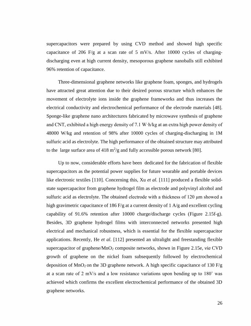
Figure 2.15 (a) Schematic illustration of the preparation steps, and (b) TEM image of
graphene wrapped hollow PANI spheres. (c) Galvanostatic charge−discharge curves of
electrochemically redued GO, PANI hollow spheres, and graphene wrapped PANI holow

xv
spheres (d) Plots of specific capacitance for PANI hollow spheres and graphene wrapped
PANI hollow spheres at various current densities [109]. (e) Digital photograph of 3D
graphene/MnO2 composite networks [112]. (f) CV curves of the flexible solid-state
supercapacitor based on the 3D graphene hydrogels at 10 mV/s for different bending
angles. (g) cycling stability of the flexible solid-state supercapacitor based on the 3D
graphene hydrogels at a current density of 10 A/g [111]. ................................................ 27
Figure 2.16 (a) Representative cyclic voltammograms of the TiO2 spheres embedded in
3D graphene networks at a scan rate of 1 mV/s. (b) charge–discharge voltage profiles of
the TiO2 spheres embedded in 3D graphene composite at a current rate of 0.5 C [118]. (c)
CV curves of the graphene foam supported Fe3O4 electrode. (d) Cycling profiles of the
graphene foam and graphene foam supported Fe3O4 electrodes [115]. ........................... 30
Figure 2.17 (a) Schematic illustration of the interface between 3D graphene/PANI
monolith electrode and S. oneidensis MR-1 bacteria. (b) Time courses of the power density
output of the MFCs equipped with a carbon cloth anode or a graphene/PANI foam anode.
(c) Polarization curves of the two types of MFCs. The inset shows the I-V relation [124].
.......................................................................................................................................... 31
Figure 3.1 Schematic representation of fabrication of graphene based spheres by tri-axial
electrospraying technique. ................................................................................................ 37
Figure 3.2 SEM images of (a) as received TEGO sheets, (b) sonicated TEGO sheets in
DMF, and (c) electrosprayed TEGO sheets in DMF without polymer. ........................... 39
Figure 3.3 (a) Raman spectra of as received TEGO, sonicated TEGO and electrosprayed
TEGO and (b) the comparison of 2D peak intensities ..................................................... 40
Figure 3.4 Entanglement concentration Ce=10C* as a function of the molecular weight of
PMMA, PS, and PAN polymers. ..................................................................................... 43
Figure 3.5 SEM images of spheres produced by (a) PMMA, (b) PMMA-0.01 wt% TEGO,
(c) PMMA-0.02 wt% TEGO, and (d) PS, (e) PS-0.005 wt% TEGO, (f) PS-0.02 wt%
TEGO. .............................................................................................................................. 45
Figure 3.6 SEM images at higher magnifications of (a) PS spheres and (b) PS-0.005 wt%
TEGO spheres. ................................................................................................................. 45
Figure 3.7 XRD spectra of (a) PMMA-TEGO spheres and (b) PS-TEGO spheres ......... 46

xvi
Figure 3.8 Schematic illustration of interactions between polymeric chains and
TEGOsheets during sphere formation .............................................................................. 46
Figure 3.9 Raman spectra of TEGO, PS spheres, and PS-0.02 wt% TEGO spheres ....... 47
Figure 3.10 FIB-SEM images of PMMA spheres containing 0.02 wt% TEGO using
methanol as a core material and a flow rate of 0.5 μL/min (a) before and (b) after ion
bombardment. .................................................................................................................. 49
Figure 3.11 FIB-SEM images of PMMA spheres containing 0.02 wt% TEGO using
methanol as a core material and a flow rate of 2 μL/min (a) before and (b) during and (c)
after ion bombardment. .................................................................................................... 49
Figure 3.12 FIB-SEM images of 20 wt% PMMA spheres containing 0.02 wt% TEGO by
using atmospheric air as a core material (a) and (b) after ion bombardment. .................. 50
Figure 3.13 SEM images of 5 wt% PAN spheres (a) before and (b) after carbonization,
and 5 wt% PAN-0.02 wt% TEGO spheres (c) before and (d) after carbonization. ......... 51
Figure 3.14 SEM images of 3.5 wt% PAN-0.05 wt% TEGO spheres (a-c) before and (d)
after carbonization ............................................................................................................ 53
Figure 3.15 (a) Raman spectra and (b) FTIR spectra of TEGO, and 5 wt % PAN-0.02 wt%
TEGO spheres before and after carbonization. ................................................................ 54
Figure 4.1 Schematic representation of the fabrication process of Pt decorated graphene-
based foam, fibers, and spheres ........................................................................................ 58
Figure 4.2 Entanglement concentration as a function of the molecular weight of PAN
polymer. ........................................................................................................................... 62
Figure 4.3. SEM images of (a) PAN-based foam, (b) PAN-based fibers and (c) PAN-based
spheres .............................................................................................................................. 63
Figure 4.4 SEM images of (a) electrosprayed, (b) reduced and (c) carbonized Pt decorated
graphene-based foam, and (d) TEM image of Pt decorated foam ................................... 65
Figure 4.5 SEM images of (a) electrospun, (b) reduced and, (c) carbonized Pt decorated
graphene-based fibers ....................................................................................................... 66
Figure 4.6 (a) and (b) TEM images of Pt decorated graphene-based fibers at different
magnifications .................................................................................................................. 66
xvii
Figure 4.7. SEM images of (a) electrosprayed, (b) reduced, (c) carbonized Pt decorated
graphene-based spheres, and (d) TEM image of Pt decorated spheres ............................ 67
Figure 4.8. Elemental mapping images of Pt element (left) and SEM images (right) of Pt
decorated graphene-based (a) foam, (b) fiber, and (c) sphere. ......................................... 68
Figure 4.9 XRD spectrum of Pt decorated graphene-based fiber after carbonization process
.......................................................................................................................................... 69
Figure 4.10 (a) FTIR spectra of neat, reduced, and carbonized Pt decorated graphene-
based fibers, and (b) Raman spectra of TEGO, Pt decorated fibers without graphene and
Pt decorated graphene-based fibers .................................................................................. 70
Figure 4.11 (a) Specific capacitance of Pt decorated graphene-based structures at different
scan rates, CVs of Pt decorated graphene-based structures at different scan rates; (b)
fibers, (c) foam, and (d) sphere electrodes ....................................................................... 72
Figure 4.12 (a) Galvanostatic charge-discharge curves of Pt decorated graphene-based
structures at a current density of 2 A/g, and (b) cycling stability of Pt decorated graphene-
based structures upon charging-discharging at a current density of 5 A/g. ..................... 74
Figure 5.1 Schematic representation of synthesis procedure of PANI coated
Mn3O4/graphene-based electrodes. .................................................................................. 81
Figure 5.2 SEM images of (a) electrospun PAN/MnCl2/TEGO fibers, (b) Mn3O4/TEGO-
CF, and (c) PANI@Mn3O4/TEGO-CF ............................................................................. 82
Figure 5.3 SEM images of (a) electrospun PAN/MnCl2/GNP fibers, (b) Mn3O4/GNP-CF,
and (c) PANI@Mn3O4/GNP-CF ...................................................................................... 83
Figure 5.4 XRD spectra of electrospun, carbonized and PANI coated composite fibers
having (a) TEGO and (b) GNP ........................................................................................ 84
Figure 5.5 FTIR spectra of electrospun, carbonized and PANI coated composite fibers
having (a) TEGO and (b) GNP ........................................................................................ 85
Figure 5.6 Raman spectra of PANI@Mn3O4/graphene based composites by the addition
of (a) TEGO and (b) GNP. .............................................................................................. 87
Figure 5.7 CV curves of (a) PANI@Mn3O4/TEGO-CF, (b) PANI@Mn3O4/GNP-CF at
different scan rates of 1, 5, and 10 mV/s, (c) specific capacitance of

xviii
PANI@Mn3O4/TEGO-CF and PANI@Mn3O4/GNP-CF at different scan rates and (d)
comparison of electrochemical performance of electrodes at 1 mV/s ............................. 89
Figure 5.8 GCD curves of (a) PANI@Mn3O4/TEGO-CF, (b) PANI@Mn3O4/GNP-CF at
current densities of 0.2, 1, and 2 A/g, and (c) cycling stability of upon charging-
discharging at a current density of 1 A/g. ........................................................................ 91

xix
LIST OF TABLES
Table 3.1. Mw, Mn, PDI and intrinsic viscosity values of shell polymers from GPC
analysis ............................................................................................................................. 41
Table 3.2: Synthesis conditions and characteristics of TEGO based PMMA and PS spheres
and their shrinkage percentages. ...................................................................................... 44
Table 4.1 The effect of polymer molecular weight and synthesis conditions on the final
morphology of structures ................................................................................................. 63
Table 4.2 CV results of Pt decorated graphene-based spheres, foam and fiber electrodes
.......................................................................................................................................... 73
Table 5.1 Elemental analysis of PANI@Mn3O4/graphene based hybrid composites ...... 83
Table 5.2 CV results of PANI@Mn3O4/TEGO-CF and PANI@Mn3O4/GNP-CF at
different scan rates ........................................................................................................... 88

1
STATE-OF-THE-ART
Graphene, a two-dimensional (2D) hexagonal lattice of sp2 carbon atoms, has been
the interest of many studies. The long-range -conjugation in graphene yields intriguing
properties such as high electrical and thermal conductivity [1], [2], large surface area [3],
good chemical stability [4] and excellent mechanical strength [5] which makes it a great
candidate in various applications such as energy storage systems, polymer composites,
and sensors [3]. However, in practical applications, 2D graphene sheets tend to restack
together due to strong π-π interactions and van der Waals forces, which lead to a
significant decrease in electrical conductivity and surface area, and this affects negatively
the utilization of graphene in many fields. To overcome this problem and provide
advanced functions with improved performance, several graphene structures such as
graphene networks [6], graphene fibers [7], and graphene spheres [8] have been
constructed mainly by chemical vapor deposition (CVD), self-assembly, and template
assisted methods. The combination of these structures and intrinsic properties of graphene
provides high surface area, excellent mechanical strength, and fast mass and electron
transport for graphene architectures.
Nevertheless, there are still some challenges in the production of graphene-based
architectures. For instance, the size of constructed structures and their properties strongly
depend on the building blocks (e.g. templates). Besides, the aforementioned techniques
include many post-treatment steps as well as harmful chemicals. Therefore, there is a need
to design new and feasible approaches that can prevent the re-stacking of graphene layers.
Taking these into account, core-shell electrospraying/electrospinning technique
becomes an ideal approach for the fabrication of graphene-based structures since it is
possible to attain multi-functionality and utilize different materials in one-step process by
eliminating deposition steps as in the self-assembly and template-assisted methods [8],
[9]. This technique brings an advantage in the energy-related areas since the electrodes
produced via this method have ability to form a continuous network, which is essential for

2
the charge transport, and provide conducting framework and excellent interconnectivity.
Moreover, this technique makes it possible to fabricate novel hybrid materials by the
combination of graphene’s high surface area and its excellent electrical conductivity with
active materials’ large specific capacity and high energy density.
In the first part of study, we designed a straightforward route for the converting 2D
graphene sheets to 3D graphene spheres by using core-shell electrospraying technique [8].
To this end, PAN, PMMA, and PS polymers were used as templates and inhibited the
agglomeration of graphene sheets by crawling into graphene layers forming intercalated
structure. The appropriate polymer concentration for the sphere formation was determined
by using Mark-Houwink-Sakurada equation. The hollowness of spheres was controlled by
changing the core solvents. Moreover, the connectivity of graphene sheets in polymeric
shell was improved by increasing carbon networks after carbonization process. Thus,
graphene-based carbon spheres with controlled hollowness became an ideal structure for
the electrode materials.
In the next step, in addition to graphene spheres, graphene-based fibers and foam
structures were also fabricated through the same method and their electorchemical
performances were investigated in details. In the electrospraying/electrospinning
techniques, the final morphology is affected by various solution properties (such as
viscosity and electrical conductivity) and process parameters (such as voltage, and flow
rate) [10]. It is worth noting that graphene-based foam was produced for the first time by
utilizing core-shell electrospraying technology instead of other available techniques like
CVD. To further increase the catalytic activity of composites, platinum nanoparticles (Pt)
were decorated on the surface of graphene-based spheres, fibers, and foam.
Electrochemical results revealed that Pt decorated 2D graphene sheets as electrode
materials did not show any capacitance behavior whereas the integration of graphene into
1D fibers and 3D foam and spherical structures in carbon network significantly improved
the capacitance characteristics.

3
Graphene-based electrodes unlike their good power density, suffer from low energy
density and poor capacitance. To solve this problem and enhance the electrochemical
performance of fabricated composites, transition metal oxides and electrically conductive
polymers can be integrated into graphene-based composites by fabricating a hybrid
structure and thus fully utilize the advantages of each component in the combined system.
Specifically, electrospun graphene-based fibers with their interconnected mesoporous
texture provides a platform for the post-synthesis and integration of various in-situ
materials like PANI into the fiber structure [11]. Therefore, in the last chapter of thesis,
manganese oxide and PANI were integrated to the graphene-based fibers due to their high
theoretical specific capacitance, low cost, and fast redox rate [12]. As the last attempt and
to fully understand the effect of graphene on the structure and electrochemical
performance of electrodes, two different types of graphene including thermally exfoliated
graphene oxide and graphene nanoplatelets were added to the fibers based on the number
of graphene layers and surface oxygen functional groups. Graphene with single
nanoplatelets and higher surface oxygen functional groups exhibited enhanced
performance due to the improved interfacial interactions between polymer matrix and
other hybrid components. Consequently, ternary hybrid composites of PANI-manganese
oxide- graphene nanoplatelets embedded carbon fibers exhibited a remarkable capacitance
improvement when compared to other reported composites.
Material from this dissertation has been published in the following forms and a paper
as well as a book chapter are under submission and publication processes:
L. Haghighi Poudeh, B. Saner Okan, J. Seyyed Monfared Zanjani, M. Yildiz, and
Y. Z. Menceloglu, “Design and Fabrication of Hollow and Filled Graphene-based
Polymeric Spheres via Core-Shell Electrospraying,” RSC Adv., vol. 5, pp. 91147–91157,
2015. (Published)
L. Haghighi Poudeh, D. Cakiroglu, F. Ç. Cebeci, M. Yildiz, Y. Z. Menceloglu, and
B. Saner Okan, “Design of Pt-Supported 1D and 3D Multilayer Graphene-Based
Structural Composite Electrodes with Controlled Morphology by Core–Shell

4
Electrospinning/Electrospraying,” ACS Omega, vol. 3, no. 6, pp. 6400–6410, 2018.
(Published)
L.Haghighi Poudeh, F. Ç. Cebeci, Y. Z. Menceloglu, M, Yildiz, B. Saner Okan,
“Free-Standing Hierarchical Hybrid Electrodes Based on PANI Coated Mn3O4/Graphene
Embedded Carbon Fibers for High Performance Supercapacitors” (Submission process)
L.Haghighi Poudeh, M. Yildiz, Y. Z. Menceloglu, B. Saner Okan,” Three
Dimensional Graphene-based Structures: Production Methods, Properties and
Applications” Graphene- Growth, Synthesis and Integration Methods, Handbook on the
Graphene Materials, WILEY-Scrivener Publisher, USA, 2018. (Accepted-under
publication)

5
LITERATURE REVIEW
Preparation of graphene
Graphene was first fabricated via micromechanical exfoliation of graphite [13]. By
using this approach, it is possible to obtain single or few-layer graphene sheets with high
quality. However, this technique is not suitable for mass-production. To address this
problem, several alternative techniques including bottom-up and top-down approaches
have been developed in order to synthesis 2D graphene sheets. Epitaxial growth [14] and
chemical vapor deposition (CVD) method [15] are the most widely used bottom-up
techniques whereas top-down approach includes electrochemical exfoliation [16] and
chemical exfoliation of graphite oxide [17]. Among top-down methods, chemical
approach has attracted great interest because of easy processability and large-scale
production thus it could be utilized in many applications [18]. On the other hand,
chemically derived 2D graphene sheets is the main component for the construction of 3D
graphene structures [19]. This technique involves the oxidation of graphite, followed by
the exfoliation process in order to obtain graphene oxide (GO) [20]. Figure 2.1 shows the
schematic representation of the different methods for the fabrication of graphene [21].
Many studies have focused on the oxidation of graphite into graphite oxide. Brodie [22],
first reported the synthesis of graphite oxide in the presence of potassium chlorate and
nitric acid. Later, Staudenmaier [23] improved the procedure by adding concentrated
sulfuric acid (H2SO4) to the mixture. However, this method was time consuming and
hazardous. In 1958, Hummers [24] used a combination of potassium permanganate and
concentrated H2SO4 in the presence of sodium nitrate. So far Hummers method with some
modifications and improvements is the most common used route for the synthesis of
graphite oxide [25], [26]. The synthesized graphite oxide is then exfoliated into single- or
few-layered GO sheets dispersed in aqueous solutions or expanded by applying heat-
treatment [27]. Finally, graphene oxide is reduced to graphene sheets by applying thermal
annealing [28] or using reducing agents such as hydrazine [29], hydroquinone [30],
sodium borohydride [31].

6
Preparation methods of 3D graphene architectures
In the past few years, large efforts have been devoted to the utilization of 3D
graphene materials with different morphologies and functionalities. In this section, the
preparation methods of 3D graphene structures are classified as assembly of GO sheets by
using different techniques and direct deposition of 3D graphene architectures through
CVD. All the methods and recent studies have been discussed in details.
Assembly of GO sheets
Assembly method is one of promising strategies for the construction of 3D graphene
architectures because of its distinct advantages including high yield, low-cost, and easy
functionalization of graphene [32]. In this technique, GO solution is preferred over
graphene since GO behaves like an amphiphilic material with hydrophilic edges and
hydrophobic basal plane [33]. Therefore, it could easily make a stable dispersion in
aqueous solutions. At the final step of assembly technique and in order to obtain 3D
graphene architectures, GO sheets are reduced whether by chemical routes or thermal
annealing to the reduced graphene (rGO) [34]. It should be noted that the driving force
behind formation of the 3D graphene architectures via assembly method is the interactions
like van der Waals forces, hydrogen bonding, dipole interactions, electrostatic interactions
and π-π stacking [35].

7
Figure 2.1 Schematic representation of the methods used for the synthesis of graphene
[21].
Self-assembly method
Self-assembly is one of the most-widely used techniques that converts 2D graphene
sheets to 3D macroscopic graphene architectures with different functionalities. The
obtained structures have great potentials to be used in various applications such as energy
storage devices [36], medicine [37], optoelectronics [38]. In this technique, 3D graphene
structures are obtained through the gelation of GO dispersion followed by the reduction
process of GO to rGO [34]. Basically, in colloidal chemistry gelation is occurred when
the electrostatic forces between colloids are changed [39]. In the case of stable GO
dispersion, there is a force balance between the van der Waals attractions of GO basal
planes and the repulsion forces of functional groups of GO sheets. Once this force balance
is broken, gelation process is started and subsequently GO sheets overlap and form
different GO morphologies such as hydrogels, organogels, or aerogels which are
physically or chemically linked to each other [40], [41]. At the final step, GO hydrogels
8
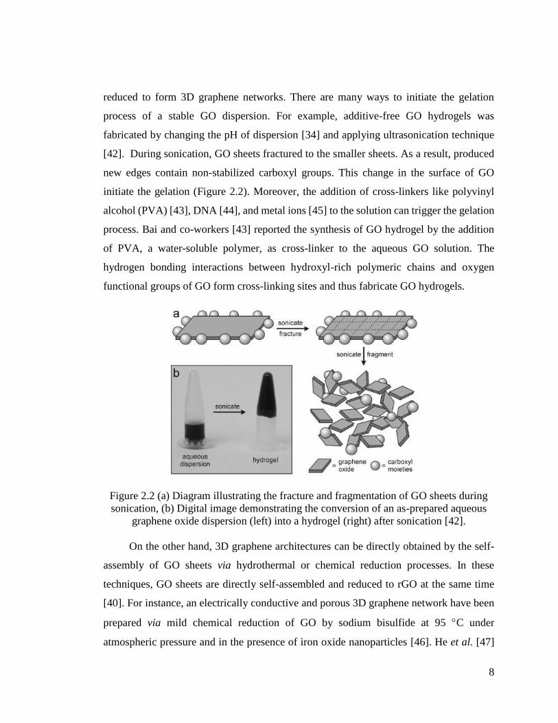
reduced to form 3D graphene networks. There are many ways to initiate the gelation
process of a stable GO dispersion. For example, additive-free GO hydrogels was
fabricated by changing the pH of dispersion [34] and applying ultrasonication technique
[42]. During sonication, GO sheets fractured to the smaller sheets. As a result, produced
new edges contain non-stabilized carboxyl groups. This change in the surface of GO
initiate the gelation (Figure 2.2). Moreover, the addition of cross-linkers like polyvinyl
alcohol (PVA) [43], DNA [44], and metal ions [45] to the solution can trigger the gelation
process. Bai and co-workers [43] reported the synthesis of GO hydrogel by the addition
of PVA, a water-soluble polymer, as cross-linker to the aqueous GO solution. The
hydrogen bonding interactions between hydroxyl-rich polymeric chains and oxygen
functional groups of GO form cross-linking sites and thus fabricate GO hydrogels.
Figure 2.2 (a) Diagram illustrating the fracture and fragmentation of GO sheets during
sonication, (b) Digital image demonstrating the conversion of an as-prepared aqueous
graphene oxide dispersion (left) into a hydrogel (right) after sonication [42].
On the other hand, 3D graphene architectures can be directly obtained by the self-
assembly of GO sheets via hydrothermal or chemical reduction processes. In these
techniques, GO sheets are directly self-assembled and reduced to rGO at the same time
[40]. For instance, an electrically conductive and porous 3D graphene network have been
prepared via mild chemical reduction of GO by sodium bisulfide at 95 C under
atmospheric pressure and in the presence of iron oxide nanoparticles [46]. He et al. [47]
9
reported the facile fabrication of 3D graphene sponges containing palladium and indium
by combination of the hydrothermal and chemical reduction techniques. In this study, GO
aqueous solution containing palladium and indium salts and vitamin C as reducing agent
were treated hydrothermally at 110 C for 6 h.
Generally, after gelation and reduction of 3D graphene architectures, a drying
procedure is needed to remove the water and organic molecules from the structure while
preserving the main framework [48]. Freeze drying as one the feasible drying techniques,
is usually applied as the final step of the assembly methods. By using this technique, it is
possible to fabricate highly porous structures with improved mechanical and electrical
properties since the pores size could be controlled by monitoring the process parameters
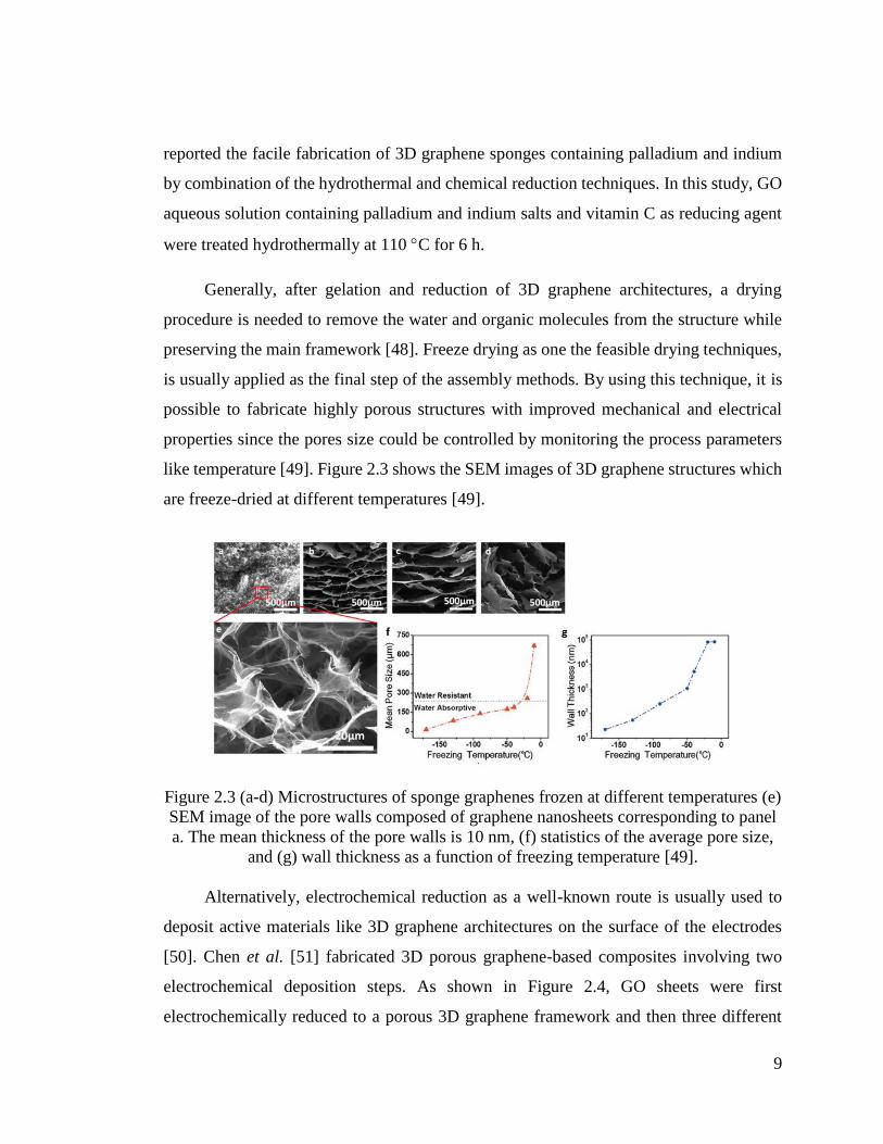
like temperature [49]. Figure 2.3 shows the SEM images of 3D graphene structures which
are freeze-dried at different temperatures [49].
Figure 2.3 (a-d) Microstructures of sponge graphenes frozen at different temperatures (e)
SEM image of the pore walls composed of graphene nanosheets corresponding to panel
a. The mean thickness of the pore walls is 10 nm, (f) statistics of the average pore size,
and (g) wall thickness as a function of freezing temperature [49].
Alternatively, electrochemical reduction as a well-known route is usually used to
deposit active materials like 3D graphene architectures on the surface of the electrodes
[50]. Chen et al. [51] fabricated 3D porous graphene-based composites involving two
electrochemical deposition steps. As shown in Figure 2.4, GO sheets were first
electrochemically reduced to a porous 3D graphene framework and then three different

10
components as conductive polymers, noble metals, and metal oxides were integrated to
the 3D porous graphene network, separately via in-situ electrochemical deposition.
Electrochemically deposited 3D graphene-based architectures can be directly used in the
electrochemical devices as high performances electrode materials.
Figure 2.4 Schematic illustration of the self-assembly of GO sheets using
electrochemical deposition [51].
Template-assisted method
3D graphene architectures can be fabricated with another feasible and convenient
way by using pre-designed 3D templates such as polystyrene (PS) [52], and silicon dioxide
(SiO2) [53] following by the reduction of GO and removing the template from the
structure. Generally, the used template is surrounded by the graphene sheets due to the
electrostatic interactions between negatively charged graphene sheets and positively
charged template. Compared to self-assembly strategy, by using this technique it is
possible to obtain more controlled structure with desirable morphology [40]. However the
size of architectures directly depends on the size of templates [8]. So far, considerable
amounts of works have focused on the production of 3D graphene-based materials using
template-assisted method. In one of the works, as shown in Figure 2.5a, positively charged

11
PS spheres as template were coated with GO sheets followed by the reduction of GO to
rGO by using hydrazine. Finally graphene hollow spheres were fabricated after calcination
at 420 ˚C for 2h to remove PS from the core [54]. Wu et al. [55] reported a facile synthesis
route for the fabrication of graphene-based hollow spheres as electrocatalysts for oxygen
reduction. As shown in Figure 2.5b, strong electrostatic interactions between
polyethylenimine functionalized SiO2 spheres and graphene sheets results in the formation
of GO-SiO2 spherical particles. After reduction process and washing with hydroflouric
acid, graphene-based hollow spheres were obtained.
Figure 2.5 Schematic illustrations of the fabrication procedure of graphene-based hollow
spheres using (a) PS [54] and (b) SiO2 [55] as templates.
In an effort to produce 3D graphene architectures with more controlled manner,
Huang and co-workers [56] reported a facile assembly method of porous graphene foams
with controlled pore sizes by the help of hydrophobic interactions of GO sheets and
functionalized SiO2 spherical templates followed by the calcination and silica etching.
Figure 2.6 represents the schematic illustration of synthesis procedure of the nanoporous
graphene foam with a controllable pore size of 30-120 nm.

12
Figure 2.6 Schematic illustration of the synthesis procedures of the nanoporous graphene
foams [56].
Electrospraying
Electrospinning/electrospraying is a simple and well-known technique to produce
graphene-based fibers and spherical or bead-like structures with the diameters ranging
from few micrometers to nanometer by adjusting the process parameters. In this process,
a strong electric field is applied between a nozzle containing graphene-based solution and
grounded metallic-plate as a collector. When the surface tension of solution at the tip of
the nozzle is overcome to the electric field, the droplet stretches and forms a continuous
jet which is collected as graphene-based fibers or spherical structures on the collector [57].
More recently, core-shell electrospinning/electrospraying has received great
attention due to its possibility to attain multi-functionality and utilize different materials
in one-step process by eliminating deposition steps as in the self-assembly and template-
assisted methods and thus it expands the potential applications of fabricated structures in
many areas including drug delivery, energy storage, sensors, and nanocomposites [8], [9].
In this technique, the final morphology is affected by various solution properties (such as
viscosity and electrical conductivity) and process parameters (such as voltage, and flow

13
rate) [10]. Up to now there are lots of attempts for the integration of graphene into fiber
structure using both classic and core-shell electrospinning technology [58]–[60]. However
very recently, Poudeh et al. [8] proposed a new design of 3D graphene-based hollow and
filled polymeric spheres through one-step core-shell electrospraying technique. In this
study, the proper polymer concentration for the sphere production were determined by
using Mark–Houwink–Sakurada equations since proper polymer concentration and
solution viscosity are required in order to obtain desired spherical morphology. In the case
of hollowness, core material should contain a solvent with a high vapor pressure than the
shell solution. Figure 2.7 represents the schematic illustration of fabrication of graphene-
based spheres using core-shell electrospraying method, which eliminates crumbling and
agglomeration problem of 2D graphene sheets and provides better dispersion of graphene
layers through polymer chains. The possible interactions between the polymeric chains
and graphene sheets during sphere formation are also shown in Figure 2.7 (left).
Figure 2.7 Schematic illustration of fabrication of 3D graphene-based spheres using
core-shell electrospraying technique and (left) possible interactions between polymeric
chains and graphene sheets during sphere formation [8].
Direct deposition of 3D graphene structures
Chemical vapor deposition (CVD) is a convenient method for the construction of
3D porous graphene networks with superior properties such as large surface area and high
14
electrical conductivity comparable to that of pristine graphene [15]. Over and above this,
in the aforementioned 3D graphene synthesis routes, chemically derived graphene is the
starting material and since during oxidation and reduction process of GO some defects are
introduced to the system, the fabricated 3D graphene structures would exhibit low
electrical conductivity when compared to 3D graphene structures growth with CVD. In
this method, graphene directly grows from organic precursors on a substrate [61].
Compared to the classic CVD process, which uses flat metal substrates as template and is
able to produce a low amount of graphene, 3D graphene architectures can be fabricated
by using different 3D templates like nickel foam in large quantities [40].
Pioneered by Chen et al. [62], they reported a general strategy for the growth of
graphene films directly on the 3D nickel template by decomposition of methane (CH4) at
1000 ˚C under ambient pressure. The wrinkles present in the surface of graphene film,
which is due to the difference between thermal expansion coefficients of nickel and
graphene, provide better interactions of graphene films with polymers. Therefore, a layer
of poly(methyl methacrylate) was easily deposited on the surface of fabricated graphene
films in order to preserve the graphene network during etching the template. Lastly, nickel
scaffold was etched in hydrochloric acid or iron chloride solution and then immersed in
hot acetone to remove polymeric layer. Figure 2.8 shows the schematic illustration of
production of 3D graphene foam by using nickel template.
It should be noted that the surface area of fabricated 3D graphene networks depends
on the number of layers in the graphene film [63]. For instance, a high surface area of 850
m2/g was reported in the case of three layer graphene foam [62]. Another important
parameter is the pore size of the chosen templates since it directly affect the final properties
of graphene foam [63]. Therefore, along with the 3D nickel foam, other template
precursors have been explored. In one of the studies, 3D graphene was growth on an
anodic aluminum oxide template with an average pore size of 95 nm at a temperature of
1200 ˚C for 30 minutes under the flows of argon, hydrogen, and methane [64]. Ning et al.
[65] demonstrated that by using a porous MgO layer as template and methane as carbon
precursor, one to two graphene layers with an extraordinary large surface area of 1654

15
m2/g and an average pore size of 10 nm were formed on the surface of the template. In
addition to the above-mentioned templates, the use of other templates such as metallic
salts were also reported [66], [67]. Over and above this, in order to tailor the pore size of
3D graphene foam, Ito el al. [68] designed a novel nanoscale nickel template by
electrochemically leaching manganese from a Ni30Mn70 precursor in a weak acid solution.
Three dimensional graphene foam with a pores size of 100 nm to 2.0 μm was achieved by
controlling the size of nickel ligaments by monitoring CVD time and temperature.
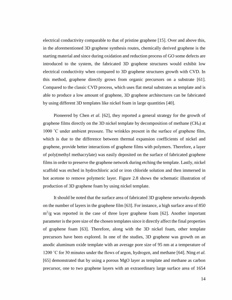
Figure 2.8 Synthesis of 3D graphene foam (GF) and integration with poly(dimethyl
siloxane) (PDMS). (a-b) CVD growth of graphene films using nickel foam as the 3D
scaffold template, (c) An as-grown graphene film after coating a thin PMMA supporting
layer, (d) A GF coated with PMMA after etching the nickel foam with hot HCl, (e) A
free-standing GF after dissolving the PMMA layer with acetone, and (f) A GF/ PDMS
composite after infiltration of PDMS into a GF [62].
As an alternative approach, the non-template direct deposition of 3D graphene
networks through plasma-enhanced CVD method was also reported. By using methane as
carbon source and substrates like gold and stainless steel, graphene sheets were firmly
adhered to the substrate and connected to each other to form 3D graphene architectures
[69].

16
3D Graphene structures
In order to enhance the functionalities and performance of the graphene-based
materials in different application areas, tremendous efforts have been devoted to develop
new 3D graphene-based architectures with different morphologies. In this section, a
review of the most typical structures, along with their characteristics have been discussed
in details.
Spheres
Graphene-based spheres, thanks to their promising properties like high electrical
conductivity and large surface area, are one of the most reported 3D graphene
architectures. Template-assisted method and assembly approach are the main techniques
for the fabrication of graphene-based spheres [55], [70], [71]. Typically, spherical
templates like SiO2 and PS are used to convert 2D graphene sheets to 3D graphene spheres.
For example, hollow graphene/polyaniline (PANI) hybrid spheres were fabricated via
layer-by-layer assembly of negatively charged GO sheets and positively charged PANI on
the surface of sulfonated PS spheres followed by the removal of the template (Figure 2.9a)
[71]. Recently, graphene nanoballs with crumpled structure were fabricated through using
an aerosol-assisted capillary compression method shown in Figure 2.9b-c. To this aim,
GO aqueous solution containing various metals or metal oxides (e.g. Pt and SnO2), were
sprayed into a tube furnace carrying nitrogen gas at a temperature of 800 ˚C which led to
a rapid evaporation of solvent and thus compression and aggregation of GO sheets and
formation of crumpled 3D graphene balls [72]. In another novel approach, hollow and
filled graphene-based spheres was fabricated through one-step core-shell electrospraying
technique without applying any post treatment or using any template (Figure 2.9d-e) [8].
Using precursor-assisted CVD technique, Lee et al. synthesized mesoporous graphene
nanoballs in which, iron chloride and PS balls were used as the catalyst precursor and
carbon source, respectively. The obtained graphene nanoballs which are given in
Figure 2.9f, showed a large specific surface area of 508 m2/g. Figure 2.9g illustrates the
schematic representation of produced mesoporous nanoballs, where PS balls were first
functionalized with carboxylic acid and sulfonic acid groups in order to enhance the

17
dispersion of PS balls in FeCl3 solution and then annealed at 1000 ˚C under hydrogen
atmosphere. During the process, the adsorbed iron ions on the surface of PS were reduced
to ion metals and thus it acted as 3D domains and catalyst for the growth of graphene
through CVD method [73].
Networks
Three-dimensional graphene networks, including graphene foams [74], [75],
hydrogels [76], [77], aerogels [78], [79] , and sponges [80], [81], are the most reported 3D
graphene architectures. CVD technique is the main method for the production of high
quality 3D graphene networks where few layers of graphene are deposited on the surface
of a metal substrate through carbon dissolution and segregation mechanism. Figure 2.10a-
d represent the CVD grown-graphene networks before and after etching the template [82].
Obtained 3D graphene networks contains less defects than chemically derived graphene
which can be also approved by Raman characterization technique [62], [82]. Since D-band
(~1350 cm-1), a characteristic peak in the Raman spectra of graphene, is related to
disorderness and its intensity changes with the defects in the structure [83], thus
disappearance of D band of CVD growth graphene network in the Raman spectra confirms
the formation of defect-free graphene (Figure 2.10f) .

18
Figure 2.9 (a) TEM image of rGO/PANI hollow spheres via layer-by-layer assembly
method [71], (b-c) SEM images of crumpled graphene balls composites synthesized by
direct aerosolization of a GO suspension mixed with precursor ions: graphene balls
composited with SnO2 (a) and Pt (b) [72], (d) FIB-SEM image of core-shell
electrosprayed hollow graphene-based PMMA spheres, (e) SEM image of core-shell
electrosprayed filled graphene-based PS spheres [8], (f) High-resolution TEM image of
mesoporous graphene nanoballs obtained by CVD, and (g) The fabrication process of
mesoporous graphene nanoballs [73]
Despite their high quality, CVD growth graphene networks suffer from large pore
sizes (e.g. hundreds of micrometers) , high porosity (e.g. 99.7%) and thus low yield [62].
To address this problem, many studies have been focused on the using of different
templates. In one of the works, Lee et al. [84] reported the fabrication of high-density 3D
graphene networks by using nickel chloride hexahydrate as catalyst precursor by
annealing it at 600 ˚C. After annealing, 3D graphene foam were grown at the different
temperatures on the cross-linked nickel skeleton in the presence of hydrogen and argon
atmosphere. Figure 2.11a-b show the difference between CVD growth 3D graphene
networks with commercial nickel foam and cross-linked nickel skeleton. The pore size of
19
3D graphene networks grown from commercial nickel template was 1-2 orders of
magnitude greater than the one grown with cross-linked nickel template. Consequently,
the smaller pore size of annealed template led to the relatively higher density of 3D
graphene networks ranging from 22 to 100 mg/cm3, compared with that of the nickel foam
(1 mg/cm3).
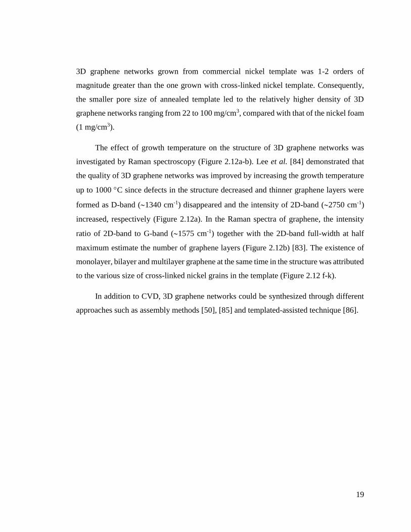
The effect of growth temperature on the structure of 3D graphene networks was
investigated by Raman spectroscopy (Figure 2.12a-b). Lee et al. [84] demonstrated that
the quality of 3D graphene networks was improved by increasing the growth temperature
up to 1000 C since defects in the structure decreased and thinner graphene layers were
formed as D-band (1340 cm-1) disappeared and the intensity of 2D-band (2750 cm-1)
increased, respectively (Figure 2.12a). In the Raman spectra of graphene, the intensity
ratio of 2D-band to G-band (1575 cm-1) together with the 2D-band full-width at half
maximum estimate the number of graphene layers (Figure 2.12b) [83]. The existence of
monolayer, bilayer and multilayer graphene at the same time in the structure was attributed
to the various size of cross-linked nickel grains in the template (Figure 2.12 f-k).
In addition to CVD, 3D graphene networks could be synthesized through different
approaches such as assembly methods [50], [85] and templated-assisted technique [86].
20
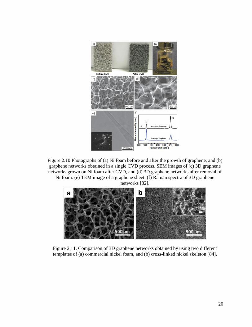
Figure 2.10 Photographs of (a) Ni foam before and after the growth of graphene, and (b)
graphene networks obtained in a single CVD process. SEM images of (c) 3D graphene
networks grown on Ni foam after CVD, and (d) 3D graphene networks after removal of
Ni foam. (e) TEM image of a graphene sheet. (f) Raman spectra of 3D graphene
networks [82].
Figure 2.11. Comparison of 3D graphene networks obtained by using two different
templates of (a) commercial nickel foam, and (b) cross-linked nickel skeleton [84].

21
Figure 2.12 (a) Typical Raman spectra of 3D graphene network grown with different
temperatures (b) Typical Raman spectra of a 3D graphene network. (c) A photograph of
the free-standing 3D graphene network. (d, e) SEM images of honeycomb-like graphene
layers after etching nickel template with FeCl3/HCl solution at different magnifications.
(f) Low-resolution TEM image of the graphene layers in 3D graphene network. (g–k)
High resolution TEM images of different graphene layers in 3D graphene network [84].
Films
In the past few years many efforts have been devoted on the fabrication of 3D
graphene films since it possesses large surface area, interconnected framework and good
mechanical strength which make it an ideal candidate for many applications specially
energy related areas. However, π- π interactions and van der Waals forces between 2D
graphene sheets cause a significant loss in the surface area and thus limits the usage of

22
graphene films in practical applications [40], [87]. For understanding the behavior of
graphene sheets in bulky structure, one can consider graphite as a packed case of graphene,
although it lacks many of the superior characteristics of single sheet graphene as a
consequence of dense packing [88]. To address this problem, further consideration such
as addition of spacer materials is essential to inhibit intersheet restacking of sheets. Up to
now, the incorporation of spacer materials such as polymers [89], noble metals [90], metal
oxides and hydroxides [91], [92], carbon materials [93], and metal organic frameworks
[94] in between the 2D graphene sheets have been reported. In addition to the above-
mentioned materials, different templates (e.g. PS, PMMA and SiO2 spherical particles)
could be used to prevent the agglomeration problem of graphene sheets. Choi et al. [95]
prepared MnO2 deposited 3D macroporous graphene frameworks by using PS spherical
particles as template following by the filtration and removal of the template (Figure 2.13).
The proposed material exhibited high electrical conductivity and surface area, which
makes it a great potential as electrode material for supercapacitors.
In another study, Yang et al. [88] by inspiration from nature demonstrated that the
water molecules can act as a natural spacer for enlarging the space in-between the
graphene sheets and inhibits the agglomeration. Therefore, the resultant graphene film
could act as a high performance electrode material since water molecules provided a
porous structure, allowing the electrolyte ions to access the inner surface area of each sheet
individually. Interestingly, although the obtained film contained almost 92 wt% water, it
showed a high electrical conductivity which might stem from face-to-face-stacked
morphology of the wet film and provided electron transport paths in the structure.
At the same time, some different methods like tape casting [96], leavening [97], light
scribing [98], and chemical activation [99] have been developed for the fabrication of
porous graphene films without using spacer materials.

23
Figure 2.13 (a) Schematic illustration of the fabrication procedure of 3D macroporous
MnO2-chemically modified graphene films, (b) SEM and (c) TEM images of the
chemically modified graphene films [95].
Other novel architectures
In addition to the aforementioned 3D graphene architectures, the fabrication of
different structures like 3D graphene scrolls [100], tubes [101], and honeycombs [102]
have also been reported. Figure 2.14 represented some of 3D graphene structures, which
are reported in the literature. In a work reported by Zhang et al. [100], nitrogen-doped
graphene ribbon assembled core-sheath MnO@graphene scrolls was fabricated by a
combination of hydrothermally assisted self-assembly and an N-doping strategy
(Figure 2.14 a-b). The obtained 3D architecture could serve as a high performance
electrode in lithium storage devices.
In another study, 3D graphene microtubings were prepared through hydrothermal
method and Cu wires as template. The morphology of graphene-based tubes is similar to
that of CNTs although the inner diameter of tubes is much larger when compared to CNT.
In this work, Cu wires were placed inside a glass pipeline and then GO dispersion was
filled in the pipeline. During hydrothermal reduction, GO sheets were wrapped around the
Cu wires and 3D graphene microtubings were obtained by removing the template and
pipeline (Figure 2.14c-d) [101].

24
Honeycomb-like 3D graphene architecture was fabricated by a simple reaction of
lithium oxide and carbon monoxide gas under low pressure at 550 ˚C, which is shown in
Figure 2.14e-f. The obtained structure exhibited a high energy conversion efficiency
which makes it a promising material in the energy storage devices [103].
Figure 2.14 (a) Schematic representation of the fabrication process for the 3D
hierarchical MnO@N-doped graphene scrolls/graphene ribbons architecture (b) FESEM
images of MnO@N-doped graphene scrolls/graphene ribbons at different magnifications
[100]. (c) SEM image of a helical graphene microtubings made by using a twist of two
Cu wires. (d) SEM image of the multichannel graphene microtubings with a channel
number of 4 [101]. (e) High-angle annular dark field image and (f) TEM image of a
honeycomb-structured graphene [103].
Applications of 3D graphene architectures
As discussed above, 3D graphene structures with improved performance and
advanced functionalities compared to 2D graphene sheets have been widely used in many
applications such as energy storage devices, sensors, polymeric composites, catalysis, etc.

25
Supercapacitors
Supercapacitors have drawn significant attention compared to other energy-storage
devices owing to their advanced properties like high power density, long cycle life [104].
Based on energy storing mechanisms, supercapacitors divide into pseudo-capacitors and
electrochemical double layer capacitors (EDLCs). Pseudo-capacitors like transition metal
oxides and conducting polymers store the charges via chemical redox-reaction on the
surface, whereas EDLCs (e.g. carbon-based materials) store the energy by ion adsorption
on the electrode-electrolyte surface. Among various carbon-based materials, graphene as
an EDLC electrode is widely used in the electrochemical energy storage systems owing
to its rich variety of dimensionality and large surface area [105]. Very recently, 3D
graphene structures became an attractive candidate for supercapacitors thanks to their
porous structure, high surface area and interconnected network which improves the
accessibility of electrolyte ions to the surface of electrode and increases the electrical
conductivity [106]. So far, different structures of 3D graphene-based materials like
spheres [52], networks [82], and films [107] have been reported as potential electrodes for
supercapacitors. In following, the supercapacitor applications of the reported graphene
structures and their related composites have been discussed in details.
Graphene spheres with hollow micro/nanostructures offer advanced characteristics
such as high surface area and shortened diffusion length for charge and mass transport
which can greatly enhance the performance as electrode for supercapacitor [108]. For
instance, graphene-wrapped polyaniline hollow spheres were fabricated by deposition of
PANI polymer on the sulfonated PS spherical templates followed by the removal of
template to obtain hollow PANI spheres. Then negatively charged GO sheets were
wrapped on the positively charged PANI hollow spheres via electrostatic interaction and
then were reduced to graphene through electrochemical reduction (Figure 2.15a-b).
Obtained graphene-wrapped polyaniline hollow spheres exhibited an excellent specific
capacitance of 614 F/g at a current density of 1 A/g and over 90% retention of the
capacitance after 500 charging-discharging cycles (Figure 2.15c-d) [109]. In another work
reported by Lee et al. [73], mesoporous graphene nanoballs as electrode for
26
supercapacitors were prepared by using CVD method and showed high specific
capacitance of 206 F/g at a scan rate of 5 mV/s. After 10000 cycles of charging-
discharging even at high current density, mesoporous graphene nanoballs still exhibited
96% retention of capacitance.
Three-dimensional graphene networks like graphene foam, sponges, and hydrogels
have attracted great attention due to their desired porous structure which enhances the
movement of electrolyte ions inside the graphene frameworks and thus increases the
electrical conductivity and electrochemical performance of the electrode materials [48].
Sponge-like graphene nano architectures fabricated by microwave synthesis of graphene
and CNT, exhibited a high energy density of 7.1 W·h/kg at an extra high power density of
48000 W/kg and retention of 98% after 10000 cycles of charging-discharging in 1M
sulfuric acid as electrolyte. The high performance of the obtained structure may attributed
to the large surface area of 418 m2/g and fully accessible porous network [80].
Up to now, considerable efforts have been dedicated for the fabrication of flexible
supercapacitors as the potential power supplies for future wearable and portable devices
like electronic textiles [110]. Concerning this, Xu et al. [111] produced a flexible solid-
state supercapacitor from graphene hydrogel film as electrode and polyvinyl alcohol and
sulfuric acid as electrolyte. The obtained electrode with a thickness of 120 μm showed a
high gravimetric capacitance of 186 F/g at a current density of 1 A/g and excellent cycling
capability of 91.6% retention after 10000 charge/discharge cycles (Figure 2.15f-g).
Besides, 3D graphene hydrogel films with interconnected networks presented high
electrical and mechanical robustness, which is essential for the flexible supercapacitor
applications. Recently, He et al. [112] presented an ultralight and freestanding flexible
supercapacitor of graphene/MnO2 composite networks, shown in Figure 2.15e, via CVD
growth of graphene on the nickel foam subsequently followed by electrochemical
deposition of MnO2 on the 3D graphene network. A high specific capacitance of 130 F/g
at a scan rate of 2 mV/s and a low resistance variations upon bending up to 180˚ was
achieved which confirms the excellent electrochemical performance of the obtained 3D
graphene networks.
27
Lithium-ion batteries
In the recent years, 3D graphene structures have been extensively studied for their
potential use as active electrodes in batteries. The integration of 3D graphene into the
structure of electrodes improves the lifetime and energy density as well as the
electrochemical performance of the electrodes since the batteries usually suffer from low
reversible capacity and cyclic life when compared to supercapacitors. Therefore, in the
design of batteries (e.g. Lithium ion batteries, LIBs) one should consider the importance
of the LIB components (e.g. electrodes and electrolyte) role in the improvement of the
battery performance. By virtue of outstanding characteristics like high surface area, porous
structure, fast mass/charge transfer, and interconnected network, 3D graphene
architectures became an outstanding candidate for high performance LIBs.
Figure 2.15 (a) Schematic illustration of the preparation steps, and (b) TEM image of
graphene wrapped hollow PANI spheres. (c) Galvanostatic charge−discharge curves of
electrochemically redued GO, PANI hollow spheres, and graphene wrapped PANI
holow spheres (d) Plots of specific capacitance for PANI hollow spheres and graphene
wrapped PANI hollow spheres at various current densities [109]. (e) Digital photograph
of 3D graphene/MnO2 composite networks [112]. (f) CV curves of the flexible solid-
state supercapacitor based on the 3D graphene hydrogels at 10 mV/s for different
bending angles. (g) cycling stability of the flexible solid-state supercapacitor based on
the 3D graphene hydrogels at a current density of 10 A/g [111].

28
So far the incorporation of various metal or metal oxides (e.g. Sn [113], NiO [114],
Fe3O4 [115], LiFePO4 [116]), and CNT [117] with graphene sheets and fabrication of 3D
graphene composites have been studied. Yu and co-workers [118] developed a
mesoporous TiO2 spheres embedded in 3D graphene networks by a facile hydrothermal
self-assembly strategy. The as prepared composite as a negative-electrode for LIBs
exhibited an excellent high-rate capacitance of 124 mA.h/g at a current rate of 20 C when
compared to that of pure TiO2 as 38 mA.h/g (Figure 2.16a-b). Such an improvement in the
electrochemical performance of the as prepared composite may attributed to the high
contact area between the electrolyte and electrode, desired diffusion kinetics for both
electrons and lithium ions and high electrical conductivity of the 3D graphene networks
as well as porous structure of TiO2 spheres.
Using microwave-assisted synthesis of self-assembled 3D graphene/CNT/Ni, Bae et
al. [117] developed a new electrode for LIBs in which CNTs were grown on graphene
sheets through tip growth mechanism by Ni nanoparticles and acted as spacer by
preventing the re-stacking of 2D graphene sheets. The synthesized 3D composite as anode
electrode for LIBs showed a reversible specific capacity of 648.2 mA.h/g after 50 cycles
at a current density of 100 mA/g.
Due to its high theoretical capacity, low cost, and nontoxic properties, Fe3O4 has
been considered as a promising electrode for LIBs. However, high volume expansion and
the low conductivity of Fe3O4 prohibit stable performance of electrodes. Integration of
conductive nanomaterials like graphene and construct 3D architectures is one the main
strategies to improve the performance of Fe3O4 based electrodes. To this aim, Luo et al.
[115] prepared 3D graphene foam supported Fe3O4 LIB which exhibited a high capacity
of 785 mA.h/g at 1C charge-discharge rate without decay up to 500 cycles. The
electrochemical properties of the graphene supported Fe3O4 LIB electrodes are given in
Figure 2.16c-d.
29
In all of the above-mentioned studies, 3D graphene provides short path length for Li
ion as well as electron transport, increases the conductivity by eliminating the
agglomeration, and thus improves the electrode performance.
Sensors
In recent years, graphene-based materials decorated with metals and metal oxides
have been studied in the various sensing devices (e.g. electorchemical sensing and bio-
sensing) due to graphene’s excellent optoelectronic properties as well as high catalytic
activity of the metals/metal oxides [119]. For example, Yavari et al. [120] prepared a 3D
graphene network for the detection of NH3 and NO2 at room temperature and atmospheric
pressure with a high sensitivity of gas detection in the ppm range. In another study, Kung
et al. [121] designed a platinum-ruthenium bimetallic nanocatalysts integrated 3D
graphene foam as a sensor for the detection of hydrogen peroxide by enhancing the surface
area and improving the effective transport in the reaction. The proposed material exhibited
a high performance toward electrochemical oxidation of H2O2 with a high sensitivity of
1023.1 mA/mM.cm2 and low detection limit of 0.04 mM.
Large-area 3D graphene interconnected GO intercalated by PANI nanofibers for the
determination of guanine and adenine have been constructed by Yang et al. [122]. By the
help of strong π-π interactions and electrostatic adsorption, positively charged guanine and
adenine adsorbed to the negatively charged proposed structure. High sensitivity, long-term
stability, and low detection limit of the prepared material makes it a reliable approach for
the determination of other small molecules.

30
Figure 2.16 (a) Representative cyclic voltammograms of the TiO2 spheres embedded in
3D graphene networks at a scan rate of 1 mV/s. (b) charge–discharge voltage profiles of
the TiO2 spheres embedded in 3D graphene composite at a current rate of 0.5 C [118].
(c) CV curves of the graphene foam supported Fe3O4 electrode. (d) Cycling profiles of
the graphene foam and graphene foam supported Fe3O4 electrodes [115].
Fuel cells
Nowadays, the finite nature of fossil fuels and rapid increase in energy consumption
persuade the scientists to design and develop renewable energy sources. To this aim, 3D
graphene architectures have attracted great attention in the fuel cells as catalysts or catalyst
carrier supporting metals and alloys in oxidation and oxygen reduction reactions (ORR)
and thus improve the performance of the fuel cell [48]. Microbial fuel cells (MFCs)
convert the chemical energy in biodegradable organic materials into electricity via bio-
oxidation process and thus provide environmental bioremediation. However, most of the
commercially available MFCs suffer from low power density and low bacteria loading on
the surface of the electrodes. To address this problem, many studies have focused on the
integration of catalysts materials to the both anode and cathode of the MFCs [123], [124].
Very recently, the use of 3D graphene as catalysts or support material has gained great

31
attention because of the large surface area and high electrical conductivity of 3D graphene
structures. In one of the studies, Yong et al. [124] suggested a macroporous and monolithic
anode electrode based on PANI hybridized 3D graphene. Owing to large surface area of
graphene, the ability of integration with bacterial films have improved and thus more
electrons passed through multiplexing and conductive pathways. The schematic
illustration of the interface and interactions between 3D graphene/PANI electrode and
bacteria is shown in Figure 2.17a. As shown in Figure 2.17b-c, obtained MFC exhibited a
high power density of 768 mW/m2, which is 4 times higher than that of the carbon cloth
MFC under the same conditions. Similarly, 3D graphene aerogel decorated with Pt
nanoparticles have been fabricated as a freestanding anode for MFCs with an excellent
power density of 1460 mW/m2. The superior performance of prepared MFC was attributed
to the high bacteria loading capacity, easy electron transfer between the bacteria and the
3D graphene/Pt, as well as fast ion diffusion in 3D pores [125].
Figure 2.17 (a) Schematic illustration of the interface between 3D graphene/PANI
monolith electrode and S. oneidensis MR-1 bacteria. (b) Time courses of the power
density output of the MFCs equipped with a carbon cloth anode or a graphene/PANI
foam anode. (c) Polarization curves of the two types of MFCs. The inset shows the I-V
relation [124].

32
Conclusions and perspectives
This review summarized the recent developments in 3D graphene-based materials
with different morphologies along with their properties and applications. So far,
considerable efforts have been devoted to the design and fabrication of 3D graphene
materials with different morphologies like spheres, films, and networks. Three-
dimensional graphene not only preserve the intrinsic properties of 2D graphene by
inhibiting the re-stacking and aggregation of sheets, but also provide advanced
functionalities with desired characteristics in the various applications like supercapacitors,
fuel cells, batteries, sensors, etc. The main approaches for the construction of 3D graphene
architectures are assembly method, template-assisted techniques, chemical vapor
deposition and electrospraying technology. Nevertheless, there are still some challenges
in the production of the 3D graphene architectures. For instance, the size of constructed
structures and their properties strongly depend on the building blocks (e.g. templates).
Besides, the main problem of the graphene sheets is their tendency to agglomerate which
strongly decreases the electrical conductivity and utilization of graphene in bulk
application. Therefore, there is a need to design new and feasible approaches that can
prevent the re-stacking of graphene layers and fabricate an ideal 3D graphene structure.
Finally, low-cost as well as mass production of 3D graphene materials are critical issues
for the practical applications. Taking these into account, 3D graphene architectures could
provide a new platform to offer advanced functionalities in various applications in the near
future.

33
DESIGN AND FABRICATION OF HOLLOW AND FILLED
GRAPHENE-BASED POLYMERIC SPHERES VIA CORE-SHELL
ELECTROSPRAYING
Introduction
Graphene with a 2D honeycomb-like structure of carbon atoms has been used in
many applications including microchips, sensors, energy storage devices, and composites
due to its unique mechanical, thermal and electronic properties[126]. There are two main
approaches in the synthesis of 2D graphene; bottom-up approach consisting of epitaxial
growth on silicon carbide and chemical vapor deposition (CVD) method, and top-down
approach including micromechanical cleavage, electrochemical exfoliation and chemical
exfoliation of graphite. The advantage of using bottom-up approach is controlling the
morphology and structure of the produced graphene sheets [127], whereas top-down
methods have some drawbacks of preserving 2D structure of graphene and limitations in
the utilization of graphene in polymer matrix and transferring graphene sheets on different
templates [128]. Graphene sheets have tendency to agglomerate in matrix and form
crumpled structure which causes a significant decrease in the surface area, electrical and
other characteristic properties [48]. To overcome this problem, several studies have
focused on the development of 3D graphene materials with different structures and
morphologies such as graphene fibers [7], [129], graphene tubes [101], graphene balls
[130] and, graphene networks [95], [131]. CVD technique is one of the widely used
bottom-up approaches for the production of 3D graphene networks, 3D porous graphene
films and macroporous structures over templates such as conductive substrates and 3D
metal substrates (e.g. nickel foam) by using different carbon sources at different conditions
[62], [132], [133]. It is also possible to convert 2D graphene sheets into 3D structures by
wet chemistry methods like water-in-oil emulsion technique without using any surfactant
[134] and hydrothermal process by mixing graphene oxide (GO) with carbon nanotubes
and metal oxides to improve surface area, electrical conductivity and capacitance
properties of 3D graphene structures [135], [136]. In the recent works, thermoelectric
properties of graphene based nanocomposites have been improved by constructing 3D
interconnected structures consisting different conducting polymers and reduced graphene
34
oxide (rGO) by in situ polymerization techniques [137]–[139]. Especially in flexible
energy storage devices, graphene based fibers and 3D porous graphene polymer networks
are fabricated as an electrode material in supercapacitors to enhance specific capacitance
and provide long-term cyclic stability [140], [141].
For the production of hollow 3D graphene structures, sphere-like templates such as
polystyrene (PS), silicon dioxide (SiO2), and titanium dioxide (TiO2) were used in several
published techniques. In one of the works, graphene hollow spheres were prepared by
covering PS balls with graphene oxide (GO) sheets and then calcination was applied at
420˚C for 2h to remove PS from the core [54]. In another work, graphene-based hollow
spheres were fabricated by electrostatic assembly of GO sheets on polyethylenimine
covered SiO2 spheres in solution phase, and subsequently followed by washing with
hydrofluoric acid and annealing processes to get hollow structure [142]. In order to
improve the catalytic properties of hollow spheres, Pd nanoparticles were decorated in
double-shelled hollow carbon spheres by using SiO2 nanospheres as template during in
situ process [143]. In the mentioned processes, the size of spheres directly depends on the
templates. It is not an easy process to control the shape of spheres and hollowness and get
higher yield of graphene balls due to the recovery process in wet-chemical methods.
Electrospinning is one of widely used techniques to produce fibers and spherical or
bead-like structures with the diameters ranging from few micrometers to nanometer by
adjusting the surface tension of the droplet and viscosity of the solution under electric field
[144]. Recently, co-axial electrospinning process has received great attention due to its
ability to produce core-shell 3D structures with different functionalities which have
distinct advantages in comparison to structures fabricated by regular electrospinning
technique [145]. In this technique, two dissimilar solutions in concentric tubes flow under
a high electric field, which is applied between the tip of the nozzle and collector. As a
result, the surface tension of a compound droplet at the tip of the nozzle is overcome
whereby the droplet stretches and forms a continuous jet which is collected on the
electrically grounded plate as a fiber [146]. In electrospinning and electrospraying, the
final morphology of the product is affected by solution properties (such as viscosity and
electrical conductivity) and process parameters (such as voltage, flow rate, and distance

35
between collector and nozzle). There are few attempts for the integration of graphene into
the fiber structure by using classic and co-axial electrospinning techniques. In one of the
studies, Promphet et al. [60] fabricated graphene based nanoporous fibers by
electrospinning of graphene/polyaniline/polystyrene mixture to be used as an
electrochemical sensor to detect heavy metals. In another work, aligned poly(3-
hexylthiophene)–graphene nanofibers produced via two-fluid coaxial electrospinning
technique were integrated into high-performance field effect transistors since graphene
acts as an electronically conducting bridge between the polymer domains in the structure
[147]. Shilpa et al. [148] synthesized core-shell composite nanofibers as an anode
electrode for Li-ion batteries by co-axial electrospinning of rGO-polyacrylonitrile (PAN)
solution as shell and zinc oxide with polymethyl methacrylate (PMMA) as core and then
applied carbonization and calcination processes to this fiber mat. In all above mentioned
relevant studies, for preserving the intrinsic properties of graphene materials in the bulk
matrix, GO and rGO are incorporated into the fiber structure by electrospinning technique
in one-step process.
One can conclude from literature that so far, considerable amount of works have
focused on the production of polymeric bead structures and core-shell microcapsules and
the investigation of their morphological changes by tailoring electrospinning parameters
[149], [150]. In the present work, thermally exfoliated graphene oxide (TEGO) sheets are
converted into 3D spheres with controlled hollowness and porosity by using three different
carrier polymers through core-shell electrospraying technique. The effect of electric field
on the exfoliation of graphene sheets is investigated by spectroscopic techniques to
understand graphene dispersion behavior in polymeric shell during electrospraying
process. In this study, shell polymers namely PS and PMMA are chosen due to their ease
for the formation of spherical topology during electrospinning process since these two
polymers are widely used as a template material for the production of 3D structures.
Additionally, PAN polymer is used to form carbon network because of its high
carbonization degree. The appropriate concentration for the production of spheres is
verified by using Mark-Houwink-Sakurada equation. Hollowness of these spheres is
controlled by changing core solvent and its flow rate. The dimension and morphology of
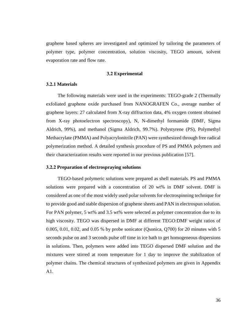
36
graphene based spheres are investigated and optimized by tailoring the parameters of
polymer type, polymer concentration, solution viscosity, TEGO amount, solvent
evaporation rate and flow rate.
Experimental
Materials
The following materials were used in the experiments: TEGO-grade 2 (Thermally
exfoliated graphene oxide purchased from NANOGRAFEN Co., average number of
graphene layers: 27 calculated from X-ray diffraction data, 4% oxygen content obtained
from X-ray photoelectron spectroscopy), N, N-dimethyl formamide (DMF, Sigma
Aldrich, 99%), and methanol (Sigma Aldrich, 99.7%). Polystyrene (PS), Polymethyl
Methacrylate (PMMA) and Polyacrylonitrile (PAN) were synthesized through free radical
polymerization method. A detailed synthesis procedure of PS and PMMA polymers and
their characterization results were reported in our previous publication [57].
Preparation of electrospraying solutions
TEGO-based polymeric solutions were prepared as shell materials. PS and PMMA
solutions were prepared with a concentration of 20 wt% in DMF solvent. DMF is
considered as one of the most widely used polar solvents for electrospinning technique for
to provide good and stable dispersion of graphene sheets and PAN in electrospun solution.
For PAN polymer, 5 wt% and 3.5 wt% were selected as polymer concentration due to its
high viscosity. TEGO was dispersed in DMF at different TEGO:DMF weight ratios of
0.005, 0.01, 0.02, and 0.05 % by probe sonicator (Qsonica, Q700) for 20 minutes with 5
seconds pulse on and 3 seconds pulse off time in ice bath to get homogeneous dispersions
in solutions. Then, polymers were added into TEGO dispersed DMF solution and the
mixtures were stirred at room temperature for 1 day to improve the stabilization of
polymer chains. The chemical structures of synthesized polymers are given in Appendix
A1.

37
Production of TEGO based 3D hollow and filled polymeric spheres by core-
shell electrospraying
Core-shell electrospraying process was performed by following two different
procedures. In the former one, the core was kept empty during spraying process and
atmospheric air was used as a core material. In the latter one, methanol was used as a core
solvent to study the effect of methanol on the hollowness and morphology of spheres.
Three different polymeric solutions with different TEGO contents were used as shell
materials. Figure 3.1 shows schematic representation of graphene based sphere fabrication
by tri-axial core-shell electrospraying technique. The size of spheres was controlled by
solution parameters (type of polymer, viscosity, surface tension, concentration, and
evaporation rate of solvent) and system parameters (voltage, distance between collector
and syringe, flow rate) through electrospraying process. Electrospraying is performed at
ambient conditions by using tri-axial electrospinning equipment purchased from Yflow
Company. At the initial step, the different distances between nozzle to collector were
examined and the optimized distance of 10 cm was set in all of the experiments owing to
homogeneous and continuous spraying process at this distance. The applied voltage was
in the range of 10–20 kV. The flow rates of shell solutions varied between 10-20 μL/min.
Methanol as a core solvent was sprayed with a flow rate in the range of 0.5-2 μL/min.
Electrospraying parameters of the produced spheres are given in details in Appendix A2.
Figure 3.1 Schematic representation of fabrication of graphene based spheres by tri-axial
electrospraying technique.

38
Carbonization process of produced spheres
Carbonization of TEGO based PAN spheres was completed in two steps. Firstly,
spheres were stabilized by an oxidation process by heating up to 300oC under air, and then
carbonization step was followed by increasing the temperature up to 1000oC under argon
atmosphere. Stabilization process changes the chemical structure of spheres and the
produced spheres become thermally stable at higher temperature without transition to
melting phase [151].
Characterization
Molecular weights and polydispersity index of polymers are measured in DMF as
an eluent by using Gel Permeation Chromatography (GPC) and the concentrations of
polymers in column are converted to the intrinsic viscosity. The morphology and inside
structure of spheres were analyzed by Leo Supra 35VP Field Emission Scanning Electron
Microscope (SEM) and JEOL JIB 4601F Focused Ion Beam (FIB/SEM dual beam
platform). Elemental analysis of spheres was conducted by using Energy-Dispersive X-
Ray (EDX) analyzing system. X-ray diffraction (XRD) measurements were carried out by
using a Bruker AXS advance powder diffractometer with a CuKα radiation source. Raman
spectroscopy was used to identify the surface characteristics of samples by using a
Renishaw inVia Reflex Raman Microscopy System with the laser wavelength of 532 nm
at room temperature in the range of 100–3500 cm-1. The functional groups of spheres were
determined by Netzsch Fourier Transform Infrared Spectroscopy (FTIR).
Results and discussion
The effect of electric field on the exfoliation process of TEGO sheets
Electrospraying process enables graphene sheets to be dispersed homogeneously in
polymer solution, prevents their agglomeration under electric field and enhances the
intercalation of polymer chains into graphene layers. SEM images of TEGO sheets after
the sonication and electrospraying processes are given in Figure 3.2 to promote
understanding the effect of electric field on the morphological changes of TEGO sheets.
Untreated TEGO has worm-like structure (Figure 3.2a). After sonication in DMF, layers

39
are separated from each other, and hence, flake dimension decreases (Figure 3.2b);
however, the structure still has multi-layered graphene [30]. Upon the being subjected to
applied electric field, the layers become more flattened whereby more transparent sheet
formation is observed (Figure 3.2c). Electric field deforms the working fluid during
electrospraying which causes loosely broad graphene layers.
Figure 3.2 SEM images of (a) as received TEGO sheets, (b) sonicated TEGO sheets in
DMF, and (c) electrosprayed TEGO sheets in DMF without polymer.
In order to detect the changes in the number of graphene layers, Raman
Spectroscopy analysis was conducted for as received, sonicated and electrosprayed TEGO
sheets and the results are presented in Figure 3.3. Raman spectrum of TEGO has three
sharp main peaks: 1338 cm-1, 1577 cm-1, and 2750 cm-1, refer to as D, G, and 2D peaks,
respectively [83]. D peak is related to disorderness and its intensity changes with the
defects in the structure. G peak corresponds to in-plane vibrations of sp2 bonded carbon
atoms and its intensity is altered due to the variation in the number of graphene layers
[27], [83]. It is known from literature, as the ratio of D to G intensities (ID/IG) increases,
sp2 bonds are broken implying that there are more sp3 bonds and more defects in the
structure[83]. In the current study, after the sonication process, there is a slight decrease
in ID/IG of untreated TEGO sample from 0.2 to 0.1. After eletrospraying of TEGO sheets,
D band completely disappears indicating that defect-free multi-layer graphene sheets are
c
a
b
a b
c

40
obtained. This decrease in D band intensity comes from the reduction in the thickness of
graphene layers which is due to the deformation of solvent. In addition, shape, width and
position of 2D peak determine the graphene layers [83]. The reduction in the intensity
ratio of G to 2D peaks (IG/I2D) indicates the decrease in the number of graphene layers.
IG/I2D values of untreated TEGO and sonicated TEGO, and electrosprayed TEGO are 2.3,
2.0 and 2.0, respectively. This shows that the sonication process breaks down graphene
layers, which are bonded by weak van der Waals forces, and then initiates the exfoliation
process. On the other hand, multi-layer structure is still preserved after electrospraying
process because there is no notable change in IG/I2D value. Furthermore, the intensity
values of 2D peak increases after each process, and 2D peak of electrosprayed TEGO gets
sharper and thus number of graphene layers decreases slightly when compared to
sonicated TEGO. The peak positions and intensity ratios are given in Appendix A3.
Figure 3.3 (a) Raman spectra of as received TEGO, sonicated TEGO and electrosprayed
TEGO and (b) the comparison of 2D peak intensities
The effect of polymer type, polymer concentration and TEGO amount on the
structural properties of graphene-based spheres
In the electrospraying process, the viscosity of solution is one of the important
parameters, which determines the morphology of structure. The higher the viscosity is, the
greater the electric field should be to be able to deform the droplet at the nozzle tip to
initiate the polymeric jet formation. The viscosity of solution depends on the molecular
(
a
)
a b
800 1200 1600 2000 2400 2800 3200
2D
G
Raman shift (cm-1
)
TEGO
D
Sonicated TEGO
Electrosprayed TEGO
Inte
nsi
ty (
a.u
.)
2500 2600 2700 2800 2900
In
tensi
ty (
a.u
.)
Raman shift (cm-1
)
2D
Electrosprayed TEGO
Sonicated TEGO
TEGO

41
weight of polymer and polymer concentration. PS, PMMA, and PAN as thermoplastic
polymers are chosen as shell materials in the production of polymer-based composites via
core-shell electrospraying process. Weight average molecular weight (Mw), number
average molecular weight (Mn), polydispersity index (PDI) and intrinsic viscosity values
of the used polymers are given in Table 3.1. These polymers have similar Mw values but
their intrinsic viscosity values are different and this directly affects polymer concentration
and viscosity of electrospun solutions.
Table 3.1. Mw, Mn, PDI and intrinsic viscosity values of shell polymers from GPC
analysis
Polymer
type
Mw
(g/mol)
Mn
(g/mol) PDI
Intrinsic
viscosity (dL/g)
PMMA 41645 20798 2.00 0.3404
PS 49283 29686 1.66 0.0781
PAN 44489 32293 1.38 0.7261
Selected polymers can form spherical structures by the optimization of the system
(applied voltage, syringe and collector distance, flow rate) and solution parameters
(polymer concentration and TEGO content). In addition to these mentioned parameters,
polymer chain entanglements affect the structural formations during electrospinning
process. The degree of entanglement is determined by calculating two limiting
concentrations, C* and Ce. C* corresponds to the solution concentration where the
hydrodynamic volumes begin to overlap and Ce is the entanglement concentration which
separates the semi-dilute unentangled and semi-dilute entangled regimes. C* is calculated
using the following equation:
C*=1/[ɳ] (1)
where [ɳ] is the intrinsic viscosity [149]. Ce value is approximately equal to 10C* for
neutral polymers in good solvent systems [152]. When polymer concentration, C, is higher

42
than Ce, bead free fibrous structures are produced due to the extensive chain entanglement.
When C*<C<Ce, bead dominant structures are generated [149]. In this study, C* values
of PMMA and PS are about 29.4 mg/mL and 128.1 mg/mL, respectively and the adjusted
concentrations (C) of PMMA and PS are 200 mg/mL which is in the range of C*<C<Ce.
In case of PAN based spheres, C* is about 13.8 mg/mL and polymer concentrations of 3.5
wt% and 5 wt% are 35 mg/mL and 50 mg/mL, respectively, and these values are between
C* and Ce.
Moreover, the optimum concentration for the fabrication of polymer based TEGO
spheres was investigated by using Mark-Houwink-Sakurada equation (Eq.2):
[ɳ]=KHMa (2)
where the constants “KH” and “a” depend on the polymer type, solvent and temperature.
The Mark-Houwink-Sakurada constants of PMMA, PS, and PAN are given in Appendix
A4. By combining Eq.1 and Eq.2, following expressions based on C* and molecular
weight is obtained for each polymer:
C*= 4×10⁴Mw-0.625 PMMA (3)
C*= 3.15×10⁴Mw-0.603 PS (4)
C*= 5.65×10⁴Mw-0.780 PAN (5)
Figure 3.4 shows the entanglement concentration Ce=10C* as a function of
molecular weight of PMMA, PS, and PAN polymers. Solid lines represent the
concentration threshold of each polymer obtained from Eq.3 (black line), Eq.4 (red line)
and Eq.5 (blue line), and each point corresponds to the polymer concentrations which are
selected for the fabrication of spheres. As seen in Figure 3.4, all of the corresponding
points attributed to the used polymer concentrations stay on the lower region of threshold
line (Ce) where bead formation is dominant.

43
Figure 3.4 Entanglement concentration Ce=10C* as a function of the molecular weight
of PMMA, PS, and PAN polymers.
Polymeric solutions were purged through outer syringe by keeping core syringe
empty during co-axial electrospraying. Table 3.2 summarizes the synthesis conditions and
characteristic properties of spheres made of PMMA and PS polymers and shrinkage
percentages of polymeric spheres after the integration of TEGO into the structure. By the
addition of TEGO in electrospun solutions, there is a significant decrease in the diameter
of TEGO based spheres when compared to neat polymeric spheres. Herein, TEGO sheets
start the shrinkage of the spheres under electric field since the surface forces increase on
droplets. After increasing the amount of TEGO, a gradual increase is observed in sphere
diameter. For instance, as seen in Table 3.2, PMMA spheres shrink by about 38% through
the addition of 0.005 wt% TEGO and the shrinkage values decreases down to 29% and
20% with 0.01 wt% and 0.02 wt% TEGO loadings, respectively. The decrease in diameter
shows the dense stacking of graphene layers in polymeric shell. It is known that oxygen
functional groups of GO in aqueous and organic solutions are negatively charged [153],
and hence, the electrostatic interaction between these negatively charged GO sheets and
positively charged polymers minimizes the size of the spherical structure. Carbon/oxygen
ratio of GO is changed regarding the type of chemical exfoliation process [24], [30]. Most
of surface oxygen functional groups can be removed by applying thermal treatment and

44
hydrophilicity of GO decreases and this allows for controlling the surface chemistry of
graphene [154]. In addition, thermal treatment extends the distance between graphene
layers and ease intercalation process is achieved during electrospraying process.
Therefore, TEGO is preferred as filler for the production of composite spheres. Increasing
TEGO amount in electrospun solution gradually imbalances the electrostatic interaction
between charges, and enlarges the sphere diameter.
Table 3.2: Synthesis conditions and characteristics of TEGO based PMMA and PS spheres
and their shrinkage percentages.
TEGO amount
(wt%)
Average diameter
of spheres (μm)
Average
shrinkage of spheres
(%)
PMMA 0 4.7 ± 0.1 -
0.005 2.9 ± 0.1 38
0.01 3.4 ± 0.3 29
0.02 3.8 ± 0.1 20
PS 0 4.5 ± 0.2 -
0.005 2.2 ± 0.1 51
0.01 2.6 ± 0.1 42
0.02 3.1 ± 0.4 32
Figure 3.5 exhibits SEM images of spheres sprayed by using air at atmospheric
pressure in the core of the syringe. After electrospraying process without any core
materials, it is observed that all types of polymers form porous and filled sphere structures.
After the addition of TEGO into the polymer, it is noted that the diameter of these spheres
decreases. Furthermore, Figure 3.6 presents SEM images of neat PS spheres and TEGO
based PS spheres at higher magnification. By the incorporation of TEGO, the porosity of
spheres decreases and the surface becomes smoother.

45
Figure 3.5 SEM images of spheres produced by (a) PMMA, (b) PMMA-0.01 wt%
TEGO, (c) PMMA-0.02 wt% TEGO, and (d) PS, (e) PS-0.005 wt% TEGO, (f) PS-0.02
wt% TEGO.
Figure 3.6 SEM images at higher magnifications of (a) PS spheres and (b) PS-0.005 wt%
TEGO spheres.
XRD characterization was performed in order to prove the presence of TEGO in
polymer spheres. In Figure 3.7, TEGO has a characteristic 002 peak at 26.5o. In the XRD
analysis of polymer-graphene based nanocomposites, 002 peak can either completely
disappear or shift to the lower region due to the intercalation of polymeric chains into
graphene sheets [155], [156]. In Figure 3.7a, PMMA shows a wide diffraction peak
spanning from 10˚ to 20˚ with a maximum intensity at 2Ɵ≈14.4˚ and the intensity of this
peak decreases as TEGO amount increases and 2Ɵ shifts to lower angel values due to the
a
b

46
complete coating of multi-layer graphene by polymer chains. Also, the diffraction peak
broadens and its intensity decreases by the incorporation of TEGO and thus composite
becomes completely amorphous structure. In Figure 3.7b, PS has a broad diffraction peak
between 15˚ and 25˚ and as the value of TEGO increases, PS diffraction peak shifts
towards lower angles and its peak becomes wider by increasing TEGO amount.
The slight shifting of polymer diffraction peak to the lower angle region and the
disappearance of 002 peak of TEGO bespeak that the electric field enhances the
distribution of graphene sheets in polymer solution so that multi-layer graphene sheets are
completely coated by polymer during sphere formation. Figure 3.8 also shows
schematically how complete coverage occurs between TEGO and polymer chains and
avoids restacking of multi-layer graphene sheets under electric field.
Figure 3.7 XRD spectra of (a) PMMA-TEGO spheres and (b) PS-TEGO spheres
Figure 3.8 Schematic illustration of interactions between polymeric chains and
TEGOsheets during sphere formation

47
Figure 3.9 shows Raman spectra of TEGO, PS, and PS-TEGO spheres. PS has
characteristic Raman peaks at 3050 cm-1 and 2900 cm-1 due to the vibration of C-H bonds,
1600 cm-1 attributed to C=C vibrations and 995 cm-1 related to aromatic carbon rings
[157]. In the Raman spectrum of the PS-0.02 wt% TEGO, the characteristic peaks of
TEGO do not appear because of the low amount of TEGO in the polymeric spheres and
overlapping of polymer main peaks with TEGO peaks. On the other hand, significant
decrease in Raman peaks of PS was observed by the integration of TEGO, which also
proves the presence of TEGO in the spheres.
Figure 3.9 Raman spectra of TEGO, PS spheres, and PS-0.02 wt% TEGO spheres
The effect of core material on the hollowness of TEGO based polymeric spheres
In order to observe the effect of the core material on the hollowness of PMMA-
TEGO spheres, methanol was used as a core solvent in electrospraying process. The shell
solvent of polymer solution is DMF with a vapor pressure of about 516 Pa whereas
methanol has higher vapor pressure about 13020 Pa. Shell formations and hollowness can
be controlled by increasing solvent vapor pressure and tailoring flow rates. In addition,
the evaporation rate depends on the flow rate of core solution so that three different flow
rates are investigated to tailor the hollowness formation in the present study. Other system
(voltage, distance between collector and syringe) and process (polymer concentration,
type of solvent, TEGO amount) parameters were kept the same in each trial to see the
800 1200 1600 2000 2400 2800
Inte
nsi
ty (
a.u
.)
2D
G
D
Raman shift (cm
-1)
TEGO
PS
PS-0.02 wt% TEGO

48
effect of flow rate on the morphologies of spheres. As the evaporation rate of the core
solvent increases, the solvent will have sufficient time for the evaporation. Hence, low
flow rate of the core solution causes hollow sphere formation, the shell is formed initially
and then core solvent evaporates through the pores of shell until the spheres reaches the
collector. Surface forces have a significant role in shaping the surface of the jet and
controlling the porosity [158]. As the flow rate of core solvent increases, the fast
evaporation of core solvent causes local phase separation, and the solvent-rich regions
leaves behind porous structures during the electrospraying process and thus porous and
filled spheres are formed. Increasing the flow rate further (i.e., 5 μL/min) leads to fiber
formation instead of spheres.
The produced spheres were cut by using an ion beam source of FIB-SEM instrument
to investigate the inside of microstructures. Figure 3.10 displays FIB-SEM images of 0.02
wt% TEGO+PMMA spheres produced utilizing the methanol as core solvent with the
lowest flow rate. Before the ion bombardment, spherical structure is clearly seen in
Figure 3.10a. After the ion bombardment, the shell material starts to melt upon increasing
the current of the ion beam whereby one can clearly observe the hollowness within the
sphere as seen in Figure 3.10b. Figure 3.11 yields the FIB-SEM images of TEGO based
PMMA spheres produced with a flow rate of 2 μL/min during the ion beam bombardment
process. The porous core structure is detected at the end of complete melting of shell
materials as seen in Figure 3.11c. This proves that increasing the flow rate of core solvent
facilitates the penetration of core solvent through shell and induces phase separations and
thus leads to porous core structure. The average diameter of spheres changes from 3.4 μm
to 4.6 μm by increasing the flow rate of core material because higher flow rate speeds up
the evaporation process of solvent. Spraying methanol with a high flow rate of 5 μL/min
totally changes the morphology and fiber formation is detected among spheres.

49
Figure 3.10 FIB-SEM images of PMMA spheres containing 0.02 wt% TEGO using
methanol as a core material and a flow rate of 0.5 μL/min (a) before and (b) after ion
bombardment.
Figure 3.11 FIB-SEM images of PMMA spheres containing 0.02 wt% TEGO using
methanol as a core material and a flow rate of 2 μL/min (a) before and (b) during and (c)
after ion bombardment.
In addition, FIB-SEM technique is used for the observation of porous core in PMMA
spheres produced by using atmospheric air in core syringe. Figure 3.12 displays FIB-SEM
images of these spheres after the ion bombardment. The structure of spheres is noticeably
porous even at longer bombardment period.

50
Figure 3.12 FIB-SEM images of 20 wt% PMMA spheres containing 0.02 wt% TEGO by
using atmospheric air as a core material (a) and (b) after ion bombardment.
The effect of carbonization on the morphology of TEGO based polymeric
spheres
PAN polymer is one of the most important precursors of carbon source in the
production of polymeric composites. Carbonization makes PAN polymer promising
especially in energy applications because its electrical and mechanical properties are
significantly improved by increasing carbon content up to 95% [151]. Instead of PS and
PMMA used as template materials having lower degradation temperatures between 300-
400oC, PAN is chosen as a carrying polymer for the carbonization process to form carbon
network with graphene sheets since PAN undergoes heating process at high temperature
in the range of 800-3000oC [151].
At the initial step of our process, 5 wt% PAN, 5 wt% PAN-0.02 wt% TEGO and 3.5
wt% PAN-0.05 wt% TEGO solutions were sprayed separately without using any core
material to produce PAN-based spheres. Fabricated spheres containing 5 wt% PAN and 5
wt% PAN-0.02 wt% formed half hollow spheres (donut-shaped structures) and
carbonization does not affect the morphologies of these structures as seen in Figure 3.13.
The reason for donut-shaped formation might be due to the combined effects of low
polymer concentration, high intrinsic viscosity and applied electric forces. Thus, a rather
interesting sphere structure is formed during the discharge process of the polymeric
mixture from the tip of syringe. Average diameters of 5 wt% PAN and 5 wt% PAN-0.02
wt% TEGO spheres are about 1.6 μm and 2.9 μm, respectively. The incorporation of
TEGO enlarges the diameter of spheres, which might stem from better dispersion and
alignment of multi-layer graphene sheets in higher viscosity of PAN solution during
electrospraying process when compared to the results of PMMA and PS solutions.
After the carbonization process, both neat PAN and TEGO based PAN spheres
shrink about 75%, and the diameters of PAN and TEGO based PAN spheres decrease
down to nanometer scale and become 400 and 700 nm, respectively. Carbonization leads
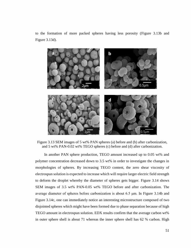
51
to the formation of more packed spheres having less porosity (Figure 3.13b and
Figure 3.13d).
Figure 3.13 SEM images of 5 wt% PAN spheres (a) before and (b) after carbonization,
and 5 wt% PAN-0.02 wt% TEGO spheres (c) before and (d) after carbonization.
In another PAN sphere production, TEGO amount increased up to 0.05 wt% and
polymer concentration decreased down to 3.5 wt% in order to investigate the changes in
morphologies of spheres. By increasing TEGO content, the zero shear viscosity of
electrospun solution is expected to increase which will require larger electric field strength
to deform the droplet whereby the diameter of spheres gets bigger. Figure 3.14 shows
SEM images of 3.5 wt% PAN-0.05 wt% TEGO before and after carbonization. The
average diameter of spheres before carbonization is about 6.5 μm. In Figure 3.14b and
Figure 3.14c, one can immediately notice an interesting microstructure composed of two
disjointed spheres which might have been formed due to phase separation because of high
TEGO amount in electrospun solution. EDX results confirm that the average carbon wt%
in outer sphere shell is about 71 whereas the inner sphere shell has 62 % carbon. High

52
carbon content in outer sphere and the wrinkles in Figure 3.14b point to the high amount
of graphene sheets and less polymer intercalation in the outer part of the structure.
Consequently, TEGO starts phase separation after the complete diffusion of polymer
chains through graphene layers and spheres are entwined together and isolated from each
other. Moreover, since the inner layer should have smaller viscosity than the outer layer
referring to the graphene content as measured by the EDX, during electrospraying process,
the inner layer should be deformed much easier than the outer layer by the combined
surface forces (i.e., electric and surface tension forces).
After heat treatment, TEGO based PAN spheres collapses totally and the boundaries
on the surface of layers and the smooth surfaces are clearly seen in Figure 3.14d. When
compared to the results having high polymer concentration and low TEGO amount given
in Figure 3.13, the porosity of surfaces in Figure 3.14 decreases significantly by increasing
TEGO and reducing polymer concentration. These results confirmed the significance of
solvent evaporation rate, solution viscosity, polymer concentration and TEGO amount on
sphere morphology.

53
Figure 3.14 SEM images of 3.5 wt% PAN-0.05 wt% TEGO spheres (a-c) before and (d)
after carbonization
Raman spectra of TEGO and 5 wt% PAN-0.02 wt% TEGO spheres before and after
carbonization are shown in Figure 3.15a. In the Raman spectrum of carbonized TEGO
based PAN spheres, two peaks appears: the peak at ~1340 cm−1 related to D band of
graphene and the peak around ~1580 cm−1 attributed to G band. ID/IG ratio of carbonized
spheres is approximately 0.9 higher than ID/IG ratio of TEGO as 0.2 which shows the
growing of graphene-like structures and reordering of aromatic groups towards graphene
networks at higher temperatures [159]. Figure 3.15b shows FTIR spectra of TEGO and
produced PAN spheres. In the FTIR spectrum of TEGO, there is no sharp peak since
thermal exfoliation of GO removes most of the oxygen functional groups and the resultant
material has high carbon content. Only a weak peak at around 1722 cm-1 appears which is
assigned to carbonyl stretching of C=O [160]. PAN spheres show characteristic peaks at
2930 cm-1, 2250 cm-1, and 1450 cm-1 which are associated with C-H bonds in CH2, nitrile
bond (C≡N), and tensile vibration of CH2, respectively [161]. By the incorporation of
TEGO into the structure, a sharp peak at 1720 cm-1 can be distinguished easily related to
the stretching vibration from carbonyl group (C=O) of TEGO. Thus, this confirms the
presence of TEGO in the structure. After applying heat treatment, the reduction in peak
intensities at 2930 cm-1 and 1450 cm-1 and the disappearance of the peak at 2250 cm-1
indicate the cyclization and dehydrogenation of TEGO based PAN spheres during
carbonization process.
400 800 1200 1600 2000 2400 2800 3200
D
TEGO
G
2D
Raman shift (cm-1)
Inte
nsi
ty(a
.u.)
PAN-0.02%wt TEGO
Carbonized PAN-0.02%wt TEGO
4000 3500 3000 2500 2000 1500 1000
TEGO
Tra
nsm
itta
nce
(%
)
Wavelength number (cm-1
)
PAN
Carbonized PAN-0.02wt% TEGO
PAN-0.02wt% TEGO
a b

54
Figure 3.15 (a) Raman spectra and (b) FTIR spectra of TEGO, and 5 wt % PAN-0.02
wt% TEGO spheres before and after carbonization.
Conclusions
In this study, hollow and filled graphene based polymeric spheres are successfully
produced by using core-shell electrospraying technique. Without applying any post
treatment or using any template, it is possible to control the hollowness of spheres by using
core solvent and changing its flow rate in one-step process. This technique also diminishes
crumbling and agglomeration of 2D graphene sheets and provides better dispersion of
graphene layers through polymer chains. In this study, PS and PMMA are used as carrier
polymers to convert 2D graphene sheets into 3D dimensional spheres since these polymers
are easily processable for bead formation and are widely used as templates to produce
hollow structures. In addition, PAN polymer is preferred as a carrier polymer to improve
connections between TEGO sheets, and after carbonization, carbon content of spheres and
graphene-like growing significantly increase. Decreasing PAN concentration and
increasing TEGO amount lead to the formation of disjointed spheres in the same structure
and this phenomenon is still under investigation. The control of solution parameters in
bead formation might give new direction to several applications including aerosols,
surface coatings, membranes, and drug delivery systems. In order to find the proper
concentration for the fabrication of polymeric spheres, a new diagram based on
concentration and molecular weight of PMMA, PS and PAN in DMF solvent is
constructed by using Mark-Houwink-Sakurada equations. The obtained data from the
diagram is consistent with the experimental results. In the presence of graphene in the
sphere structure, the intercalation and shifting in XRD patterns towards lower angles
indicate the presence of graphene sheets in polymer matrix. In the proposed technique, the
number of polymeric shells can be increased by increasing syringe number in
electrospraying set-up, and multi-layer composite spheres having enhanced multi-
functionality can be produced by using different polymers with different degree of
hydrophilicity. In addition, catalysts can be deposited on the surface of polymeric shells
and electrolytes can be inserted in core part during electrospraying. Consequently, multi-
axial core shell electrospraying technique will increase accessible surface area of 2D

55
graphene sheets and preserve characteristic properties of graphene in bulk systems, and
open up new directions especially in energy applications such as Li-ion batteries, fuel
cells, and supercapacitors.

56
DESIGN OF Pt SUPPORTED 1D AND 3D MULTI-LAYER
GRAPHENE-BASED STRUCTURAL COMPOSITE ELECTRODES WITH
CONTROLLED MORPHOLOGY BY CORE-SHELL
ELECTROSPINNING/ELECTROSPRAYING
Introduction
In the recent years, a rapid increase in the global energy consumption persuades
scientists to develop new eco-friendly energy storage devices. In the field of energy
storage, electrode design plays a significant role by providing high surface area, fast
electron mobility, high electrical conductivity and good chemical stability to attain high
electrochemical performance [162]. Especially carbon materials are widely used as an
electrode material in electrochemical energy storage systems owing to their rich variety
of dimensionality and large surface area [105]. Among various carbon-based materials,
graphene becomes a promising candidate since it has long-range π conjugation and thus
fast electron mobility which makes it extremely attractive for energy storage devices [61].
There are different types of graphene production techniques by using top-down and
bottom-up approaches. The main problem in the utilization of graphene in bulk
applications is its restacking and agglomeration and the formation of crumpled structure
leading to a significant decrease in the surface area, electrical conductivity and thus great
loss of electrochemical activity. Up to now, many efforts have been made to overcome
this obstacle by the integration of 2D graphene sheets into macroscopic structures through
different methods including chemical vapor deposition, encapsulation, self-assembly and
wet spinning [40], [163]. With these methods, it is possible to convert graphene into
several structures such as graphene fibers [164], spheres [130], films [165], and networks
[95].
Template-assisted method and self-assembly technique are the most common used
strategies to obtain 3D graphene-based structures. In one of the studies, Fan et al. [109]
fabricated graphene-wrapped polyaniline hollow spheres as an electrode material by using
polystyrene spheres as template and obtained a high specific capacitance of 614 F/g at a
current density of 1 A/g and maintained the capacitance at around 90% after 500 cycles.

57
In another work, Xu et al. [166] produced microporous carbon spheres incorporated into
3D graphene frameworks via wet chemistry and self-assembly techniques, which showed
a specific capacitance of 288.8 F/g at a current density of 0.5 A/g. However, in these
aforementioned processes, it is not easy to control structural properties such as porosity
and hollowness since the morphology directly depends on the chosen templates. At this
point, electrospinning is an alternative and easy method for the production of graphene-
based structures in the form of spheres [8], [167] and fibers [168] by adjusting the polymer
concentration and surface tension of droplet. The electrodes produced by electrospinning
have an ability to form a continuous network, which is essential for the charge transport
and provides conducting framework and excellent interconnectivity. In one of work, Kim
et al. [169] examined the electrochemical behavior of graphene/carbon nanofiber
composite electrode produced via classical electrospinning technique by using graphene
oxide (GO) and polyacrylonitrile (PAN) as carbon precursor having high conductivity and
a specific capacitance of 146.6 F/g at a current density of 1 mA/cm-2. Recently, core-shell
electrospinning has received great attention in order to attain multi-functionality and
utilize different materials in one-step process by eliminating coating and deposition steps
and thus expand the potential applications of fabricated structures [168], [170]. Kou et al.
[171] fabricated polyelectrolyte-wrapped graphene core-sheath fibers as high-energy
density electronics by co-axial electrospinning of reduced GO solution as core and sodium
carboxymethyl cellulose as shell material following by reduction and washing processes.
Instead of morphology design in electrode structures, the integration of noble metals
improves electrical conductivity and electrochemical stability in graphene electrodes used
in Li-ion batteries, fuel cells and supercapacitors [172]. Among them, Pt has gained great
interest due to its lowest over potential and stability which facilitate the electron transport
during redox reactions [172], [173]. For instance, Zhang et al. [174] fabricated
graphene/Pt films having a high capacitance of 120 F/g at high scan rate of 50 A/g to
enhance the conductivity of charges, and thus give higher reversible capacitance at high
rates. So far, there are several attempts for the fabrication of graphene-based fibers as
electrodes in the energy storage systems by applying classical and core-shell
electrospinning techniques. To the best of our knowledge, there is no related work to

58
control the dimension of graphene based electrodes in different forms of foam and sphere
by applying core-shell electrospinning technology.
In the present study, Pt deposited 1D graphene-based fiber and 3D graphene-based
sphere and foam electrodes were produced by core-shell electrospinning/electrospraying
techniques. Figure 4.1 shows the schematic representation of fabrication process for Pt
decorated graphene-based foam, fibers and spheres by core–shell electrospraying. During
electrospinning, thermally exfoliated multi-layer graphene layers were transformed into
the three different forms of fiber, foam and sphere by using a carrier polymer by altering
solution parameters of polymer concentration and molecular weight of polymer and
process parameter of applied voltage. In the electrode structure, PAN polymer was used
as a carrier to increase carbon network. Due to the high catalytic activity and good
chemical stability against oxidation, Pt particles was chosen as catalyst and deposited at
low loadings in the structures. Structural and morphological properties of structures were
analyzed by spectroscopic and microscopic techniques in details. The electrochemical
performance of Pt deposited graphene-based carbon structures as electrodes was
investigated by cyclic voltammetry and galvanostatic charge-discharge.
Figure 4.1 Schematic representation of the fabrication process of Pt decorated graphene-
based foam, fibers, and spheres
Experimental
Materials
Polyacrylonitrile (PAN, Mw: 150000 g/mol), N, N-dimethyl formamide (DMF,
99%), chloroplatinic acid (H2PtCl6, 8 wt% in H2O), and hydrazine hydrate (N2H4) were
59
purchased from Sigma-Aldrich. Low molecular weight PAN (Mw: 45000 g/mol) was
synthesized through free radical polymerization method [175]. TEGO Grade 2 (thermally
exfoliated graphene oxide) having average number of graphene layers of 27 calculated
from XRD data by using Debye Scherer equations and 4% oxygen content was obtained
from Nanografen Co. The characterization results of TEGO were given in Appendix B1.
Fabrication of graphene-based structures by core-shell electrospinning
Foam, fiber and sphere-like graphene-based structures were produced at ambient
conditions by using tri-axial electrospinning equipment purchased from Yflow Company.
PAN polymer containing graphene sheets were used as a shell material in the proposed
structures. In the shell material, 0.02 wt% TEGO based on the weight of solvent was
dispersed in DMF by probe sonicator for 20 minutes to get homogeneous dispersion. The
optimum amount of 0.02 wt% TEGO was chosen for the production of electrospun
structures and the detailed results about optimization process were given in our previous
paper [8]. Two different polymer concentrations of 1 wt% and 5 wt% PAN with a
molecular weight of Mw=150000 g/mol were adjusted to get foam and fiber structures,
respectively. In case of graphene-based sphere production, low molecular weight PAN
polymer (Mw=45000 g/mol) was used as 5 wt% PAN in 0.02 wt% TEGO/DMF mixture.
For the production of graphene-based foam, 1 wt% PAN solution was
electrosprayed with an applied voltage of 18 kV and flow rate of 5 μL/min. In the case of
fibers, as-prepared 5 wt% PAN solution was electrospun with an applied voltage of 10 kV
and flow rate of 8 μL/min. For the production of graphene-based spheres, electric field
was adjusted as 13 kV and flow rate was kept as 10 μL/min by using 5 wt% low Mw PAN
based solution. All electrospinning/electrospraying experiments were performed with
constant working distance of 10 cm and the core part of nozzle was kept empty during
each process.
Pt deposition
In each material, H2PtCl6 was added into the solution to observe 0.05 wt% Pt based
on the polymer weight in the final structure. The amount of Pt was optimized by the
60
addition of two different amounts of 0.05 wt% and 0.1 wt% of Pt in the fiber structure. As
it can be seen in Appendix B2, high amount loading of 0.1 wt%, results in the serious
agglomeration problem in the surface of fibers. Thus 0.05 wt% was selected as optimized
amount for the decoration of Pt on the surface of graphene-based architectures. In case of
graphene-based foam and fibers, Pt catalyst was dispersed in electrospun solution and
impregnated in the matrix during electrospinning process in one step process. On the other
hand, Pt particles were dispersed on electrospun graphene spheres after carbonization
process to improve capacitance value.
In order to obtain Pt from H2PtCI6, hydrazine hydrate was used as reducing agent in
distilled water (1:100, v:v). Aqueous hydrazine solution is used as a non-solvent for PAN
polymer not to damage the structure [176]. Electrosprayed/electrospun graphene-based
foam and fibers were immersed into hydrazine hydrate solution and kept for 1 day at room
temperature and then washed several times with water and kept for drying in oven. After
the reduction process, the color of the materials turned into gray indicating that Pt ions
were reduced into Pt metal particles. For graphene-based spheres, the same steps of
reduction were applied after carbonization process.
Carbonization process
Heat treatment of the produced fibers, spheres and foam was performed in two steps
to increase carbon amount in the structure and thus improve electrochemical properties of
the designed electrodes. In the first step, samples were stabilized by applying oxidation
process by heating up to 300˚C under air for 30 min and thus the structures became more
stable at higher temperature without transition into melting phase. In the second step, these
samples were heated up to 1000˚C under argon atmosphere.
Electrode preparation and their electrochemical tests
Electrochemical performance of the carbonized samples was evaluated by
PARSTAT MC (Princeton Applied Research) under a three-electrode system in 0.5 M
H2SO4 aqueous electrolyte using platinum wire as a counter electrode and Ag/AgCl as a
reference electrode in a typical potential range for aqueous electrolytes of 0-0.8 V.
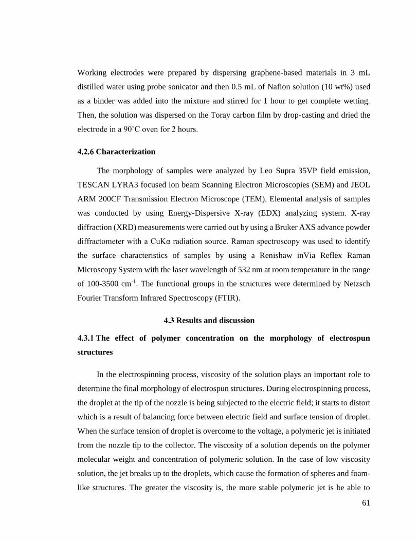
61
Working electrodes were prepared by dispersing graphene-based materials in 3 mL
distilled water using probe sonicator and then 0.5 mL of Nafion solution (10 wt%) used
as a binder was added into the mixture and stirred for 1 hour to get complete wetting.
Then, the solution was dispersed on the Toray carbon film by drop-casting and dried the
electrode in a 90˚C oven for 2 hours.
Characterization
The morphology of samples were analyzed by Leo Supra 35VP field emission,
TESCAN LYRA3 focused ion beam Scanning Electron Microscopies (SEM) and JEOL
ARM 200CF Transmission Electron Microscope (TEM). Elemental analysis of samples
was conducted by using Energy-Dispersive X-ray (EDX) analyzing system. X-ray
diffraction (XRD) measurements were carried out by using a Bruker AXS advance powder
diffractometer with a CuKα radiation source. Raman spectroscopy was used to identify
the surface characteristics of samples by using a Renishaw inVia Reflex Raman
Microscopy System with the laser wavelength of 532 nm at room temperature in the range
of 100-3500 cm-1. The functional groups in the structures were determined by Netzsch
Fourier Transform Infrared Spectroscopy (FTIR).
Results and discussion
The effect of polymer concentration on the morphology of electrospun
structures
In the electrospinning process, viscosity of the solution plays an important role to
determine the final morphology of electrospun structures. During electrospinning process,
the droplet at the tip of the nozzle is being subjected to the electric field; it starts to distort
which is a result of balancing force between electric field and surface tension of droplet.
When the surface tension of droplet is overcome to the voltage, a polymeric jet is initiated
from the nozzle tip to the collector. The viscosity of a solution depends on the polymer
molecular weight and concentration of polymeric solution. In the case of low viscosity
solution, the jet breaks up to the droplets, which cause the formation of spheres and foam-
like structures. The greater the viscosity is, the more stable polymeric jet is be able to

62
travel through grounded collector [177]. In our previous work [8], we showed the effect
of polymer concentration and molecular weight on the formation of different polymeric
structures by using Mark-Houwink-Sakurada equation (Appendix B3). Figure 4.2
represents the concentration as a function of molecular weight of PAN where, solid line
shows the concentration threshold of PAN polymer where above and on the line fiber
formation is dominant (see Appendix B). By moving toward lower regions, spherical and
foam-like structures are started to form. On the other hand, each point in the graph
corresponds to the different PAN concentration with different molecular weight, which
are selected for the fabrication of fibers, spheres, and foam colored as red, purple, and
blue, respectively. Hence, it is possible to get the structures with the desired morphology
and size such as spheres [8], foams, and fibers [57] by tailoring system (e.g. flow rate,
applied voltage, working distance between nozzle and collector) and solution parameters
(e.g. polymer concentration).
Figure 4.2 Entanglement concentration as a function of the molecular weight of PAN
polymer.
In the first part of work, structural morphologies of electrospun/electrosprayed
structures were tailored by controlling polymer molecular weight and polymer
concentration. Three different polymeric solutions with different concentrations of 1 wt%
and 5 wt% and different PAN molecular weights were prepared to monitor the effect of
0 50000 100000 150000 200000
1
10
100
PAN
Fiber
Foam
Sphere
Weight average molecular weight, Mw (g/mol)
C (
mg/m
L)

63
concentration and viscosity on the morphology of structures. Table 4.1 summarizes the
synthesis conditions of graphene-based structures. The results showed that low polymer
concentration brought about the formation of porous interconnected foam. Figure
Figure 4.3a represents SEM image of 1 wt% PAN electrospun foam with average pore
size of 100 μm. On the other hand, as PAN concentration increased up to 5 wt%,
homogeneous and uniform fibers having an average diameter of 150 nm were obtained as
seen in Figure 4.3b. Graphene-based spheres having donut-shaped structure with an
average diameter of 1.6 μm were fabricated by electrospraying 5 wt% PAN (Mw= 45000
g/mol) shown in Figure 4.3c and the production details of these spheres were given in our
previous publication [8]. The reason behind the formation of donut-shaped structure is the
combined effects of low polymer concentration, high intrinsic viscosity and applied
electric forces at the tip of syringe during the discharge of electrospun solution [8].
Consequently, it is possible to convert TEGO sheets into 1D and 3D structures by using a
carrier polymer by tailoring the parameters of applied voltage and solution viscosity.
Table 4.1 The effect of polymer molecular weight and synthesis conditions on the final
morphology of structures
Morphology Mw of PAN
(g/mol)
Polymer
concentration
(wt%)
Applied
voltage
(kV)
Flow rate
(μL/min)
Foam 150000 1 18 5
Fiber 150000 5 10 8
Sphere 45000 5 15 10
Figure 4.3. SEM images of (a) PAN-based foam, (b) PAN-based fibers and (c) PAN-
based spheres

64
Pt decorated 1D and 3D graphene-based structures
Electrospinning/electrospraying technique provides homogenous distribution of
graphene sheets into polymeric matrix by preventing their agglomeration and restacking
under electric field [8], [178]. In order to increase the conductivity, Pt particles were
integrated into graphene-based foam, fibers, and spheres during electrospinning and after
post-process. In case of foam and fiber structures, Pt nanoparticles were integrated during
electrospraying/electrospinning. Figure 4.4a shows SEM image of electrosprayed
graphene-based foam having pores in the range of micron size. It should be noted that
desirable pore size could be achieved by controlling the polymer drying time and adjusting
solvent vapor pressure [179], [180]. After reduction process, structure still preserved its
framework shown in Figure 4.4b. In order to improve carbon content, carbonization was
applied on the reduced foam. Figure 4.4c represents SEM image of Pt decorated 3D
graphene-based foam after carbonization process. Pt nanoparticles with an average length
of 50 nm in cubical form were distributed homogeneously on the surface of graphene-
based foam (Figure 4.4d). The large diameter of Pt might stem from the growth of Pt
nanoparticles during the heat treatment of foam. According to Sellin et al., [181] Pt grains
under inert atmosphere (e.g. argon) started the reconstruction after 250 ˚C resulted in the
grain growth and agglomeration of Pt particles.

65
Figure 4.4 SEM images of (a) electrosprayed, (b) reduced and (c) carbonized Pt
decorated graphene-based foam, and (d) TEM image of Pt decorated foam
Figure 4.5 shows the fabrication steps of Pt decorated graphene-based fibers.
Graphene sheets and Pt nanoparticles were integrated into the PAN solution with a
polymer concentration of 5 wt%, where higher concentration of PAN polymer resulted in
the formation of homogeneous fibers with an average diameter of 100 nm. Figure 4.5a
shows the SEM image of graphene-based fibers. After the reduction process, well-
dispersed Pt nanoparticles appeared on the surface of fibers shown in Figure 4.5b where
the diameter of reduced fibers increased up to 250 nm due to the growth of Pt nanoparticles
all over the surface of fibers. Figure 4.5c represents the SEM image of carbonized
graphene-based fibers having leaf-like structure owing to the expansion of graphene and
the growth of Pt during carbonization. As seen in Figure 4.6a, after applying heat
treatment, Pt particles with the average size of 45 nm were grown and graphene layers
were exfoliated on the surface of carbonized fibers. The large diameter of Pt particles, as
discussed above, is due to the Pt agglomeration during carbonization process. In this
structure, Pt catalysts were on graphene sheets but not seen clearly in TEM image in
Figure 4.6b since leaf-like exfoliation on fiber surface caused the formation of wrinkled
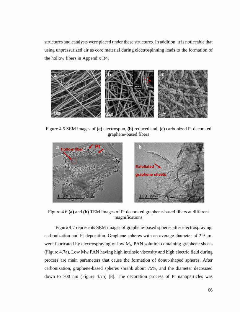
66
structures and catalysts were placed under these structures. In addition, it is noticeable that
using unpressurized air as core material during electrospinning leads to the formation of
the hollow fibers in Appendix B4.
Figure 4.5 SEM images of (a) electrospun, (b) reduced and, (c) carbonized Pt decorated
graphene-based fibers
Figure 4.6 (a) and (b) TEM images of Pt decorated graphene-based fibers at different
magnifications
Figure 4.7 represents SEM images of graphene-based spheres after electrospraying,
carbonization and Pt deposition. Graphene spheres with an average diameter of 2.9 μm
were fabricated by electrospraying of low Mw PAN solution containing graphene sheets
(Figure 4.7a). Low Mw PAN having high intrinsic viscosity and high electric field during
process are main parameters that cause the formation of donut-shaped spheres. After
carbonization, graphene-based spheres shrank about 75%, and the diameter decreased
down to 700 nm (Figure 4.7b) [8]. The decoration process of Pt nanoparticles was

67
performed on the carbonized graphene-based spheres shown in Figure 4.7c. Pt
nanoparticles with an average diameter of 4 nm were decorated homogeneously on the
surface of graphene-based spheres in Figure Figure 4.7d. The addition of Pt particles after
carbonization process brought about the formation of smaller Pt particles rather than foam
and fibers since heat treatment accelerates the growth process of Pt particles.
Figure 4.7. SEM images of (a) electrosprayed, (b) reduced, (c) carbonized Pt decorated
graphene-based spheres, and (d) TEM image of Pt decorated spheres
Figure 4.8 represents the distribution of Pt on the surface of graphene-based foam,
fibers, and spheres. Although Pt was loaded with equal amounts into the structures, there
were variations in the distribution of Pt particles on the surface of structures coming from
the morphological differences of the samples. EDX results confirm that the average Pt
wt% in sphere structure is 20, whereas in the case of fiber and foam this amount decreases
down to 5 and 9, respectively. The elemental mapping results of the samples are given in
Appendix B5 and Appendix B6. The Pt particles on fiber and foam surface were
distributed uniformly but during heat treatment, the size of Pt particles was increased to

68
45 nm and 50 nm, respectively due to the reconstruction and agglomeration of particles
[181]. In the case of graphene-based spheres, Pt nanoparticles was distributed densely with
a size of few nanometers.
Figure 4.8. Elemental mapping images of Pt element (left) and SEM images (right) of Pt
decorated graphene-based (a) foam, (b) fiber, and (c) sphere.
XRD characterization was performed to confirm the presence of Pt in graphen based
structures.
Figure 4.9 shows the XRD spectrum of Pt decorated graphene-based fibers. TEGO
shows a characteristic 002 peak at 2θ= 26.5˚ [8]. On the other hand, the characteristic
peaks at 2θ = 39˚, 45.8˚, and 67˚ are attributed to the (111), (200), and (220) planes of the
face-centered cubic (FCC) crystal lattice of Pt, respectively [182]. The high intensity of Pt

69
characteristic peaks compared to graphene characteristic peak may stem from the low
amount of TEGO in the structure and growing of Pt particles during heat treatment
process.
Figure 4.9 XRD spectrum of Pt decorated graphene-based fiber after carbonization
process
Figure 4.10a exhibits FTIR spectra of Pt decorated neat electrospun, reduced and
carbonized graphene-based fibers. PAN shows characteristic peaks at 2930 cm-1, 2250 cm-
1, and 1450 cm-1 belonging to C–H bonds in CH2, nitrile bond (C≡N), and tensile vibration
of CH2, respectively [161]. There is a significant decrease in the intensity of C=O bond at
around 1660 cm-1 after hydrazine reduction and this proves successful reduction process
and decrease in oxygen functional groups. After applying heat treatment, no characteristic
peak was observed due to high carbon content in fiber structure. Figure 4.10b displays
Raman analysis of TEGO sheets, Pt decorated fiber and Pt decorated graphene-based fiber.
TEGO sheets have three main characteristic peaks at 1338 cm-1, 1577 cm-1, and 2750 cm-
1 known as D, G, and 2D peaks, respectively [8]. On the other hand, in the Raman spectrum
of Pt decorated fiber, the presence of D peak at 1342 cm-1 and G peak at 1596 cm-1 are
attributed to the disordered carbon structure and in-plane vibration of sp2 carbon atoms,
respectively [178]. The ratio of D and G peak intensities (ID/IG) is a way to measure the
defects in the carbon-based structures. As ID/IG increases, sp2 bonds are broken and thus
20 30 40 50 60 70 80
C (200)
Pt (111)
Pt (200)
Pt decorated graphene-based fiber
Pt (220)
2Theta
Inte
nsity (
a.u
.)

70
more defects appear in the structure [83]. Pt decorated fibers show an ID/IG ratio of 0.93
whereas by the addition of TEGO to the structure, this value increases up to 0.98, which
indicates the growing of carbon network on graphene sheets after carbonization. The
structural properties of Pt decorated graphene-based foam and spheres are given in
Appendix B7 and Appendix B8, respectively.
Figure 4.10 (a) FTIR spectra of neat, reduced, and carbonized Pt decorated graphene-
based fibers, and (b) Raman spectra of TEGO, Pt decorated fibers without graphene and
Pt decorated graphene-based fibers
Investigation of electrochemical performance of 1D and 3D electrodes
The electrochemical behavior of Pt decorated graphene-based structures with
different morphologies was investigated by standard cyclic voltammetry (CV) and
galvanostatic charge-discharge technique in a three-electrode cell. The specific
capacitance of electrodes was measured using following equation:
𝐶 = 𝐼𝑑𝑉/(2𝑚𝜗∆𝑉) (1)
where C represents the specific capacitance (F/g), I is the current (A), m indicates the mass
of active materials (g), 𝜗 is the potential scan rate (V/s), and ∆V is the applied voltage
window (V). Table 4.2 gives the summary of CV results of fabricated electrodes regarding
the dimension of the structures. In order to understand the dimension effect of graphene
sheets on the electrochemical behavior of electrodes, CV test of Pt decorated 2D TEGO

71
sheets was also performed at the initial stage. TEGO-based electrode did not show any
capacitance behavior due to its nearly linear CV curve as seen in CV plot of Pt decorated
TEGO sheets (Appendix B9). Figure 4.11a exhibits the graphs of specific capacitance of
Pt decorated graphene-based structures as a function of scan rates. Capacitance values of
spheres, foam and fibers decreased gradually as the current rate increased. The specific
capacitances of Pt decorated graphene-based structures at a scan rate of 1 mV/s were
calculated as 118 F/g for spheres, 54 F/g for foam, and 8 F/g for fibers. An increase in
capacitance values of hybrid electrodes when compared to neat TEGO-based electrodes
stem from the diffusion of PAN polymer chains through graphene layers during
electrospinning since PAN can serve as a spacer by preventing re-stacking of sheets and
increase the electron mobility. In addition, Pt decorated TEGO showed poor capacitance
behavior when it was utilized without using as a polymer carrier due to the sheet-sheet
junctions that limit the conductivity and thus capacitance [183]. Another reason of low
capacitance performance is the intercalation of Pt through layers and this decreases the
catalytic activity of Pt particles. Afterwards, graphene sheets were converted into 1D
fibers, the structure started to show capacitance activity but still has low value as about 8
F/g since electrospinning process buried Pt particles deeply inside the structure and hence
electrochemical reaction was not observed effectively [184]. Figure 4.11b represents CV
curves of graphene-based fibers at scan rates of 1, 5, 10, 50, and 100 mV/s where the
capacitance value was calculated based on the lowest scan rate. Pt decorated graphene-
based foam and spheres as 3D structures showed enhanced specific capacitance of 54 F/g
and 118 F/g, respectively in comparison of 1D fibers. The CV plots of Pt decorated
graphene-based foam are shown in Figure 4.11c. 3D graphene structures consist of micro
and macro interconnected pores which results in a high surface area and fast ion/electron
transport channels [106]. However, the diameter of Pt nanoparticles is considerably high
as about 50 nm and thus the electrochemical activity of Pt decorated graphene-based foam
decreased. Therefore, Pt decorated graphene-based foam although its unique structure did
not show better capacitance behavior. In case of sphere electrode, Pt particle size
decreased down to 5 nm and the structure became more porous as seen in SEM image of
Figure 4.7c and thus electrode/electrolyte interface was improved and catalytic activity
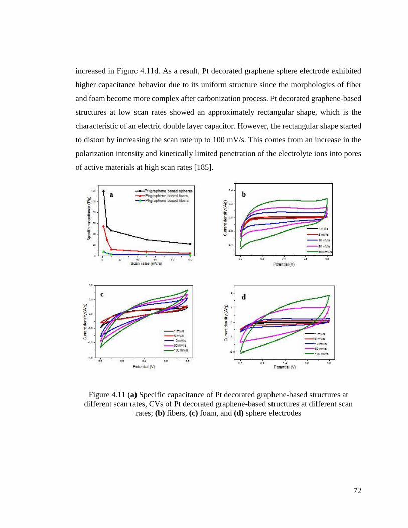
72
increased in Figure 4.11d. As a result, Pt decorated graphene sphere electrode exhibited
higher capacitance behavior due to its uniform structure since the morphologies of fiber
and foam become more complex after carbonization process. Pt decorated graphene-based
structures at low scan rates showed an approximately rectangular shape, which is the
characteristic of an electric double layer capacitor. However, the rectangular shape started
to distort by increasing the scan rate up to 100 mV/s. This comes from an increase in the
polarization intensity and kinetically limited penetration of the electrolyte ions into pores
of active materials at high scan rates [185].
Figure 4.11 (a) Specific capacitance of Pt decorated graphene-based structures at
different scan rates, CVs of Pt decorated graphene-based structures at different scan
rates; (b) fibers, (c) foam, and (d) sphere electrodes

73
Table 4.2 CV results of Pt decorated graphene-based spheres, foam and fiber electrodes
Different
dimensional electrodes
Specific capacitance (F/g)
at a scan rate of 1 mV/s
Pt/TEGO ND*
Pt/Spheres 118
Pt/Foam 54
Pt/Fibers 8
*ND: Not detected
The galvanostatic charge-discharge measurements were carried out in a 0.5 M
H2SO4 electrolyte between 0 and 0.8 V at various current densities ranging from 2 to 10
A/g. The representative charge-discharge curves of Pt decorated graphene-based
structures at a current density of 2 A/g are presented in Figure 4.12a. Pt decorated
graphene-based structures showed nearly triangular shape, which is a behavior of electric
double-layer capacitance electrodes [186]. On the other hand, Pt decorated graphene-
based spheres showed a much longer discharge time at the same current density when
compared to other structures. This indicates higher specific capacitance, which is also
confirmed by CV results of graphene-based spheres. In practical electrodes, long-term
cycling stability of electrodes is one of the critical parameters. In the present work, the
cycling stability test was carried out under the current density of 5 A/g for 1000 cycles of
charging-discharging. In Figure 4.12b, specific capacitance of Pt decorated graphene-
based spheres decreased about 12% after 1000 cycles of charge-discharge whereas the
values of Pt decorated graphene-based foam and fibers decreased 6% and 10%,
respectively. The slight decrease in the cycle stability of spheres stem from a rapid
shrinking of pores of spheres due to its 3D nature that results in a decrease in the
capacitance as time passes which is in the agreement with coulombic efficiency results
given in Appendix B10. Consequently, 1D and 3D graphene-based structures showed
comparably higher cycling stability when compared to the other reported values in the
literature [106], [187].
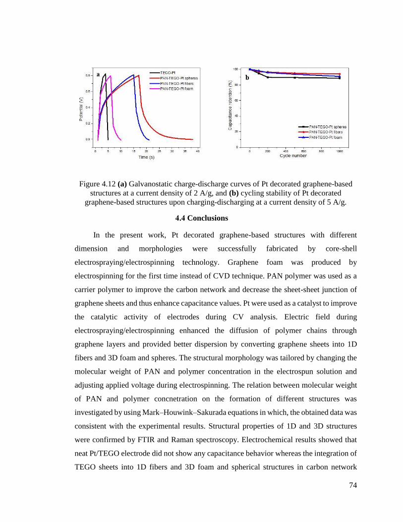
74
Figure 4.12 (a) Galvanostatic charge-discharge curves of Pt decorated graphene-based
structures at a current density of 2 A/g, and (b) cycling stability of Pt decorated
graphene-based structures upon charging-discharging at a current density of 5 A/g.
Conclusions
In the present work, Pt decorated graphene-based structures with different
dimension and morphologies were successfully fabricated by core-shell
electrospraying/electrospinning technology. Graphene foam was produced by
electrospinning for the first time instead of CVD technique. PAN polymer was used as a
carrier polymer to improve the carbon network and decrease the sheet-sheet junction of
graphene sheets and thus enhance capacitance values. Pt were used as a catalyst to improve
the catalytic activity of electrodes during CV analysis. Electric field during
electrospraying/electrospinning enhanced the diffusion of polymer chains through
graphene layers and provided better dispersion by converting graphene sheets into 1D
fibers and 3D foam and spheres. The structural morphology was tailored by changing the
molecular weight of PAN and polymer concentration in the electrospun solution and
adjusting applied voltage during electrospinning. The relation between molecular weight
of PAN and polymer concnetration on the formation of different structures was
investigated by using Mark–Houwink–Sakurada equations in which, the obtained data was
consistent with the experimental results. Structural properties of 1D and 3D structures
were confirmed by FTIR and Raman spectroscopy. Electrochemical results showed that
neat Pt/TEGO electrode did not show any capacitance behavior whereas the integration of
TEGO sheets into 1D fibers and 3D foam and spherical structures in carbon network

75
improved capacitance characteristics. Specifically, a high capacitance was obtained from
3D graphene-based spheres having 118 F/g at a scan rate of 1 mV/s due to the
homogeneous decoration of Pt particles with a diameter of 4 nm on the surface after post-
treatment. After carbonization process, foam and fiber structures lost their uniformity, and
graphene exfoliation and destruction in the structure and agglomeration of Pt particles
caused to decrease their electrochemical performance. Therefore, the size and place of Pt
particles are needed to be controlled for to get higher catalytic activity. After 1000 cycle
of charging-discharging, Pt deposited graphene-based structures exhibited high cyclic
stability and retention of capacitance due to the deposition of Pt particles into electrode
structure. Consequently, core-shell electrospinning technology provided to adjust the
dimension of structures by the embedment of graphene sheets and preventing
agglomeration of graphene sheets by applying electric field to electrospun solutions.
Especially this study brings a new insight for the fabrication of high performance electrode
materials for energy storage devices.

76
FREE-STANDING HIERARCHICAL HYBRID ELECTRODES
BASED ON PANI COATED Mn3O4/GRAPHENE EMBEDDED CARBON
FIBERS FOR HIGH PERFORMANCE SUPERCAPACITORS
Introduction
Supercapacitors, also known as ultracapacitors, are considered as one of the
promising energy storage devices which offer long cyclic life, high power density and safe
operation [188], [189]. According to energy storing mechanisms, supercapacitors are
divided into two common groups, which are pseudo-capacitors and electrochemical
double layer capacitors (EDLCs). Pseudo-capacitors such as transition metal oxides and
conducting polymers store the charges via fast chemical redox reactions on their surface
[190] and thus exhibit high theoretical capacitance. In the last years, manganese oxide, a
typical metal oxide, has been considered as a promising pseudo-capacitor due to the high
theoretical specific capacitance, low cost, and environmental friendly nature [12]. Besides,
electrically conductive polyaniline (PANI) has been widely studied owing to its high
electrical conductivity, fast redox rate and high theoretical specific capacitance [189]. On
the other hand, EDLCs store the energy by reversible physical adsorption of ions without
any chemical reactions [40]. Compared with pseudo-capacitors, EDLCs suffer from low
energy density and poor capacitance [191]. To solve this problem and improve the
electrochemical performance, pseudo-capacitors can be integrated into EDLCs by
fabricating a hybrid structure and thus fully utilize the advantages of each component in
the combined system.
Recently, graphene-based supercapacitors have attracted significant attention for
EDLCs and other energy storage devices due to its fast electron mobility and high
electrical conductivity [106]. Especially the design of ternary hybrid electrodes as novel
hierarchical structures can effectively boost the electrochemical performance [192]–[194].
For instance, Wu et al. [195] fabricated a high performance supercapacitor based on
ternary composite of manganese dioxide nanorods and graphene nanoribbons embedded
in PANI matrix by two-step in-situ polymerization method and obtained a high specific
capacitance of 472 F/g at a current density of 1 A/g and a cyclic stability of 79.7% after

77
5000 cycles. In another study, Huang and co-workers [196] investigated the
electrochemical properties of reduced graphene oxide/manganese oxide/PANI composite
electrodes by using potassium permanganate (KMnO4) as manganese oxide source and
also initiating agent for the polymerization of aniline followed by the hydrothermal
method. This synthesized composite having fiber-like structures showed a high specific
capacitance of 344 F/g and capacitance retention of nearly 100% after 6000 cycle of
charging-discharging. Consequently, hydrothermal approach and wet chemistry method
are mostly used to synthesize manganese oxide/graphene/polyaniline hybrid composites
in the literature.
In particular, the deposition of manganese oxide on the surface of graphene is
achieved through redox deposition by using oxidizing agents such as KMnO4 but this kind
of a strong agent can dramatically change the nature of the composites during the
fabrication process [11]. Additionally, all of the aforementioned techniques are time-
consuming and need many post-treatment processes and harmful chemicals. At this point,
there is a tendency for the development of alternative approaches for the integration of
manganese oxide on the graphene. Very recently, our group reported the design and
fabrication of graphene-based hybrid composites in an easy and controllable manner via
core-shell electrospinning [197]. With this technique, it is possible to integrate different
functional nanoparticles and polymers and thus utilize hybrid materials with improved
performance. Moreover, electrospun graphene-based fibers with their interconnected
mesoporous texture provides a platform for the post-synthesis and integration of various
in-situ materials like PANI into the fiber structure [11].
In this study, we reported a facile and straightforward route for the fabrication of
hierarchical PANI coated graphene and manganese oxide embedded in carbon fibers (CF)
via core-shell electrospinning. Polyacrylonitrile (PAN) polymer was selected as a carrier
to increase the interconnections in fiber network and also carbon content. In addition,
KMnO4 was replaced by mild manganese (II) chloride tetrahydrate, which can oxidize to
manganese oxide during heat treatment. In order to fully understand the effect of graphene
on the structure and electrochemical performance of electrodes, two different types of

78
graphene including thermally exfoliated graphene oxide (TEGO) and graphene
nanoplatelet (GNP) were selected based on the number of graphene layers. In order to
increase the conductivity, the surfaces of these new design composite electrodes were also
coated by PANI via in-situ polymerization of aniline monomer for the production of
supercapacitor electrodes. Structural and morphological properties of composite
electrodes were analyzed by spectroscopic and microscopic techniques in detail.
Experimental
Materials
The following materials have been used for the experiments: polyacrylonitrile
(PAN, Mw: 150000 g/mol, Sigma-Aldrich), N, N-dimethyl formamide (DMF, Sigma-
Aldrich, 99%), aniline (Sigma-Aldrich, 99.5%), ammonium persulfate (APS, Sigma,
98%), manganese (II) chloride tetrahydrate (Sigma-Aldrich, 99.99%), sulfuric acid
(H2SO4, Sigma-Aldrich, 98%). Thermally exfoliated graphene oxide (TEGO) and
graphene nano platelet (GNP) were purchased from NANOGRAFEN Co., Turkey. TEGO
contains 27 graphene layers and 2.1 wt% oxygen content and its surface area is about 11
m2/g. GNP has single plates with the length of 50 nm having 8.1 wt% oxygen functional
groups and its surface area is around 85 m2/g. The densities of TEGO and GNP are 1.05
g/cm3 and 2.30 g/cm3, respectively.
Preparation of Mn3O4/graphene embedded carbon fibers by core-shell
electrospinning
Mn3O4/graphene-based fibers were fabricated by using tri-axial electrospinning
equipment purchased from Yflow Company and converted into carbon fibers (CF) by
applying heat treatment. For the fabrication of Mn3O4/TEGO-CF, 0.03 wt% TEGO and 1
wt% MnCl2 were dispersed in DMF by sonicating the mixture for 15 min. PAN polymer
with a concentration of 5 wt% was then poured into the sonicated dispersion followed by
stirring for 1 day in order to attain homogeneous and stable mixtures. In the case of
Mn3O4/GNP-CF, 0.5 wt% GNP and 1 wt% MnCl2 were sonicated in DMF solvent and
then 5 wt% PAN polymer was added into the mixture and stirred for 1 day. The

79
electrospinning process was performed with an applied voltage of 12 kV, flow rate of 9
μL/min with the nozzle to collector distance of 10 cm while atmospheric air was used as
core material. For two different graphene solutions, electrospinning parameters were kept
same. The amount of graphene used in electrospun solutions was dependent on the density
of graphene and thus TEGO was adjusted as 0.03 wt% due to its comparably lower density
than GNP. Finally, Mn3O4/TEGO-CF and Mn3O4/GNP-CF were obtained by performing
heat treatment where MnCl2 was oxidized to Mn3O4 and PAN was carbonized. During
heat treatment, fibers were stabilized by applying oxidation process up to 300˚C under air
for 2 h and then heated up to 800˚C for 2 h under argon atmosphere.
Fabrication of PANI@Mn3O4/graphene carbon fibers
PANI polymer was coated on the surface of fabricated fibers by in-situ chemical
polymerization of aniline monomer in the presence of ammonium persulfate (APS) as the
initiator. Briefly, Mn3O4/graphene-CF were immersed in 50 mL of 1 M H2SO4 aqueous
solution containing 0.5 mL of aniline monomer. In the following, 0.5 g of APS was
dispersed in 20 mL distilled water and then added dropwise to the aniline containing acid
solution. The mixture was stirred at about 0˚C for 2 h followed by the filtration and
washing process with ethanol and distilled water. Finally, the obtained composite samples
were kept at 60 ˚C in oven for drying.
Electrode preparation and their electrochemical tests
Electrochemical performances of the produced composite electrodes were evaluated
by PARSTAT MC (Princeton Applied Research) under a three-electrode system in 1 M
H2SO4 aqueous electrolyte using platinum wire as a counter electrode and Ag/AgCl as a
reference electrode in the potential range of 0-0.8 V. PANI@Mn3O4/graphene-CF samples
were directly used as free-standing working electrodes without using any binder in
electrochemical tests.
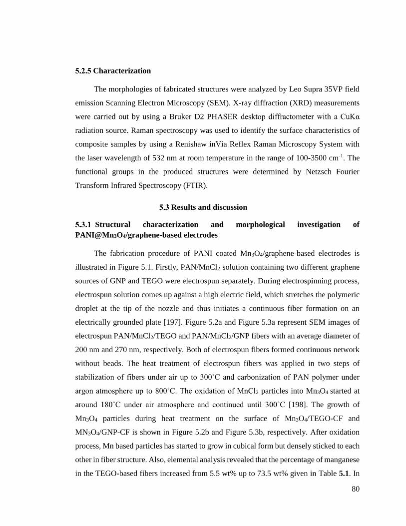
80
Characterization
The morphologies of fabricated structures were analyzed by Leo Supra 35VP field
emission Scanning Electron Microscopy (SEM). X-ray diffraction (XRD) measurements
were carried out by using a Bruker D2 PHASER desktop diffractometer with a CuKα
radiation source. Raman spectroscopy was used to identify the surface characteristics of
composite samples by using a Renishaw inVia Reflex Raman Microscopy System with
the laser wavelength of 532 nm at room temperature in the range of 100-3500 cm-1. The
functional groups in the produced structures were determined by Netzsch Fourier
Transform Infrared Spectroscopy (FTIR).
Results and discussion
Structural characterization and morphological investigation of
PANI@Mn3O4/graphene-based electrodes
The fabrication procedure of PANI coated Mn3O4/graphene-based electrodes is
illustrated in Figure 5.1. Firstly, PAN/MnCl2 solution containing two different graphene
sources of GNP and TEGO were electrospun separately. During electrospinning process,
electrospun solution comes up against a high electric field, which stretches the polymeric
droplet at the tip of the nozzle and thus initiates a continuous fiber formation on an
electrically grounded plate [197]. Figure 5.2a and Figure 5.3a represent SEM images of
electrospun PAN/MnCl2/TEGO and PAN/MnCl2/GNP fibers with an average diameter of
200 nm and 270 nm, respectively. Both of electrospun fibers formed continuous network
without beads. The heat treatment of electrospun fibers was applied in two steps of
stabilization of fibers under air up to 300˚C and carbonization of PAN polymer under
argon atmosphere up to 800˚C. The oxidation of MnCl2 particles into Mn3O4 started at
around 180˚C under air atmosphere and continued until 300˚C [198]. The growth of
Mn3O4 particles during heat treatment on the surface of Mn3O4/TEGO-CF and
MN3O4/GNP-CF is shown in Figure 5.2b and Figure 5.3b, respectively. After oxidation
process, Mn based particles has started to grow in cubical form but densely sticked to each
other in fiber structure. Also, elemental analysis revealed that the percentage of manganese
in the TEGO-based fibers increased from 5.5 wt% up to 73.5 wt% given in Table 5.1. In
81
comparison of electrospun PAN/MnCl2/TEGO with Mn3O4/TEGO-CF, Cl was
completely eliminated after heat treatment indicating successful oxidation of manganese.
A similar trend was also observed for GNP based electrospun and CF fibers. At the final
step, PANI as conductive polymer was deposited on the surface of fibers by in-situ
chemical polymerization method. The presence of oxygen functional groups on the surface
of both GNP and TEGO facilitates the polymerization of PANI and provide homogeneous
coating since these functional groups are acting as anchor sites by attaching to the aniline
monomer [195]. After polymerization, the percentage of nitrogen on the surface of
PANI@Mn3O4/TEGO-CF and PANI@Mn3O4/GNP-CF increased from 1.5 wt% up to 19
wt% and 18.5 wt%, respectively which supported the formation of PANI on the surface
of composites. Figure 5.2c and Figure 5.3c shows SEM images of PANI coated
Mn3O4/TEGO-CF and Mn3O4/GNP-CF, respectively. Needle-like PANI-based nanowires
were observed on the surface of both types of carbon fibers.
Figure 5.1 Schematic representation of synthesis procedure of PANI coated
Mn3O4/graphene-based electrodes.

82
Figure 5.2 SEM images of (a) electrospun PAN/MnCl2/TEGO fibers, (b) Mn3O4/TEGO-
CF, and (c) PANI@Mn3O4/TEGO-CF
a
c
b a
c
b

83
Figure 5.3 SEM images of (a) electrospun PAN/MnCl2/GNP fibers, (b) Mn3O4/GNP-CF,
and (c) PANI@Mn3O4/GNP-CF
Table 5.1 Elemental analysis of PANI@Mn3O4/graphene based hybrid composites
Samples C
(wt%)
O
(wt%)
N
(wt%)
Mn
(wt%)
Cl
(wt%)
Electrospun
PAN/MnCl2/TEGO
46 8.5 34.5 5.5 5.5
Mn3O4/TEGO-CF 4 21 1.5 73.5 -
PANI@Mn3O4/TEGO-CF 53 27 19 1 -
Electrospun
PAN/MnCl2/GNP
47.5 6 35 5.5 6
Mn3O4/GNP-CF 10 16.5 1.5 72 -
PANI@Mn3O4/GNP-CF 45.5 35 18.5 1 -
a
c
b a b
c

84
XRD characterization was performed to investigate the structural changes in the
produced fibers in step-wise process and results are given in Figure 5.4. Electrospun
samples has a broad characteristic peak at 2Ɵ=16.5˚ associated to 100 plane of PAN
polymer [161]. A sharp peak at 2Ɵ=26˚ belongs to the 200 graphitic plane of both TEGO
and GNP [8]. In Figure 5.4a, small reflection peaks at 2Ɵ=15.5˚, 20˚ and 31˚ indicate the
presence of manganese chloride hydrate in the electrospun fiber structure (PDF 25-1043).
After carbonization, a typical crystalline pattern of tetragonal hausmannite Mn3O4 (PDF
80-0382) is observed in both XRD spectra of Mn3O4/TEGO-CF and Mn3O4/GNP-CF.
Also, the reflection peaks at 2Ɵ=26˚ is also attributed to the 200 graphitic plane of TEGO
and GNP. In Figure 5.4b, an additional carbon peak is seen at 2Ɵ=45˚ corresponding to
100 carbon plane of Mn3O4/GNP-CF [199]. However, carbon peaks are not dominant in
the XRD spectrum of Mn3O4/TEGO-CF due to much lower TEGO content in fiber
structure. In the last process by PANI coating, there is a broad XRD peak appeared at
2Ɵ=23˚ attributed to the emeraldine salt form of PANI [194]. Therefore, XRD supported
successful and homogeneous deposition of PANI on the surface of fibers by suppressing
the characteristic peaks of other components in the structure.
Figure 5.4 XRD spectra of electrospun, carbonized and PANI coated composite fibers
having (a) TEGO and (b) GNP
In order to further understand the structural changes of composites, FTIR spectral
analysis was conducted after each production step. In the FTIR spectrum of electrospun
PAN/MnCl2/TEGO in Figure 5.5a, the bands at 2930 cm-1, 2243 cm-1, 1452 cm-1 are
a b

85
attributed to the C–H bonds in CH2, nitrile bond (C≡N), and tensile vibration of CH2 of
PAN polymer, respectively[8]. A peak at 1631 cm-1 is related to the C=C aromatic
vibration of TEGO [192]. Moreover, O-H vibration at 3375 cm-1 corresponds to the
MnCl2.H2O in the electrospun fiber. It is not possible to see Mn-Cl stretching bands in the
present spectrum since these bands appear in the IR regions of 300-200 cm-1 [200]. After
carbonization, characteristic PAN peaks disappeared in the FTIR spectrum of
Mn3O4/TEGO-CF meaning the successful cyclization and dehydrogenation[8]. A sharp
peak at 595 cm-1 is assigned to Mn-O stretching vibration band of Mn3O4 [192]. After
PANI deposition, new structure has C=C stretching vibrations of quinoid and benzoid
rings in the emeraldine salt at 1565 cm-1 and 1473 cm-1 [71], C-N stretching of the
secondary aromatic amine at 1281 cm-1 [201], and C-H bending at 781 cm-1 [71]. The
bands in the region of 1000-1150 cm-1 is related to the bending vibration of C-H mode
[194]. A decrease in the intensity of Mn-O stretching vibration of Mn3O4 at 591 cm-1
indicates that ternary hybrid is fully covered by PANI polymer. A similar trend was also
observed for GNP-based composites shown in Figure 5.5b.
Figure 5.5 FTIR spectra of electrospun, carbonized and PANI coated composite fibers
having (a) TEGO and (b) GNP
In addition to FTIR characterization, Raman spectroscopy was also conducted to
confirm the existence of graphene in the composite fibers. Typical D and G bands of
graphene-based materials are seen at 1356 cm-1 and 1578 cm-1 in Figure 5.6. In the Raman
3500 3000 2500 2000 1500 1000 500
PAN/MnCl2/TEGO fibers
Wavelength number (cm-1)
Tra
ns
mit
tan
ce (
%)
Mn3O
4/TEGO-CF
PANI@Mn3O
4/TEGO-CF
3500 3000 2500 2000 1500 1000 500
PAN/MnCl2/GNP fibers
T
ran
sm
itta
nc
e (
%)
Mn3O
4/GNP-CF
PANI@Mn3O
4/GNP-CF
Wavelength number (cm-1)
a b

86
spectra of ternary hybrid fibers, there is a slight shift in the peak position of D band due
to the π-π* interactions between aniline monomer with TEGO and GNP [201]. It is well
known that D band is related to the disorderness and intensity ratio of D and G bands
(ID/IG) is changed by the alteration of structures [202]. ID/IG values of electrospun
PAN/MnCl2/TEGO and PAN/MnCl2/GLS were calculated as 1.01 and 1.44, respectively.
Whereby, after heat treatment process, the values decreased down to 0.97 and 0.99,
respectively. This stems from the rearrangement of the structures in a more ordered
manner and an increase in the crystallinity due to the formation of highly crystalline
Mn3O4 phase. The peak at 645 cm-1 is attributed to the symmetric stretching vibration of
Mn-O [203] whereby the intensity of this peak significantly increased after heat treatment
and this verifies the successful oxidation of manganese during heat treatment. Also, this
peak is shifted to the left after PANI decoration owing to the H-bonding interactions
between Mn3O4, graphene, and PANI together [204], [205]. Moreover,
PANI@Mn3O4/TEGO-CF and PANI@Mn3O4/GNP-CF hybrids have additional peaks at
1157 cm-1 corresponding to the aromatic C-H in-plane bending of benzoid ring [71], 1399
cm-1 attributed to C-N+ stretching [206], 1529 cm-1 due to the stretching vibrations of C=N
of emeraldine base [207], and 1648 cm-1 related to the C-C stretching of the benzenoid
ring [206]. Consequently, spectroscopic analyses were justifed the creation of carbon
network, the existence of graphene layers and the phase changes in manganese based
catalyst.
a b
87
Figure 5.6 Raman spectra of PANI@Mn3O4/graphene based composites by the addition
of (a) TEGO and (b) GNP.
Electrochemical performance of PANI coated Mn3O4/graphene CF electrodes
Cyclic voltammetry (CV) analysis was carried out to examine the electrochemical
behavior of PANI@Mn3O4 TEGO-CF and PANI@Mn3O4/GNP-CF composite electrodes
in 1 M H2SO4. In Figure 5.7a and Figure 5.7b, all the CV curves of both GNP and TEGO
based ternary hybrids are close to rectangular shape without any redox peaks. Especially
GNP based electrodes is more like an ideal EDLC when compared to one having TEGO
at the rate of 1 mV/s as seen in Figure 5.7d. The absence of Faradaic peaks in CV curve
of a hybrid composite which contains pseudo-capacitor components like manganese oxide
and PANI is attributed to effective interactions of redox active sites together and thus easy
electron transfer in a wide range of potentials [208].
The specific capacitance of electrodes based on the CV tests (Ccv) was calculated by
the following equation
VmIdVCcv 2 (1)
where Ccv is the specific capacitance (F/g), I is the current (A), m is the weight of active
materials (g), ϑ is the scan rate (V/s), and ∆V is the potential window (V). Table 5.2
summarizes the specific capacitance values of the produced electrodes. Specific
capacitance values of PANI@Mn3O4/TEGO-CF at different scan rates of 1, 5, and 10 mV
were calculated as 326, 100, and 63 F/g, respectively. Typically, by increasing the scan
rate, the specific capacitance value started to decrease due to the kinetically limited
penetration of electrolyte ions. In the case of PANI@Mn3O4/TEGO-CF, by increasing the
scan rate up to 20 mV/s, a sharp decrease of capacitance to 20% of its initial value was
observed which designates that PANI@Mn3O4/TEGO-CF have poor rate capability
(Figure 5.7c). Despite the high specific capacitance, CV of PANI@Mn3O4/TEGO-CF
exhibited quasi-reversibility behavior since the charge stored under the positive current is
much higher than that of negative current. This might come from the polarization and
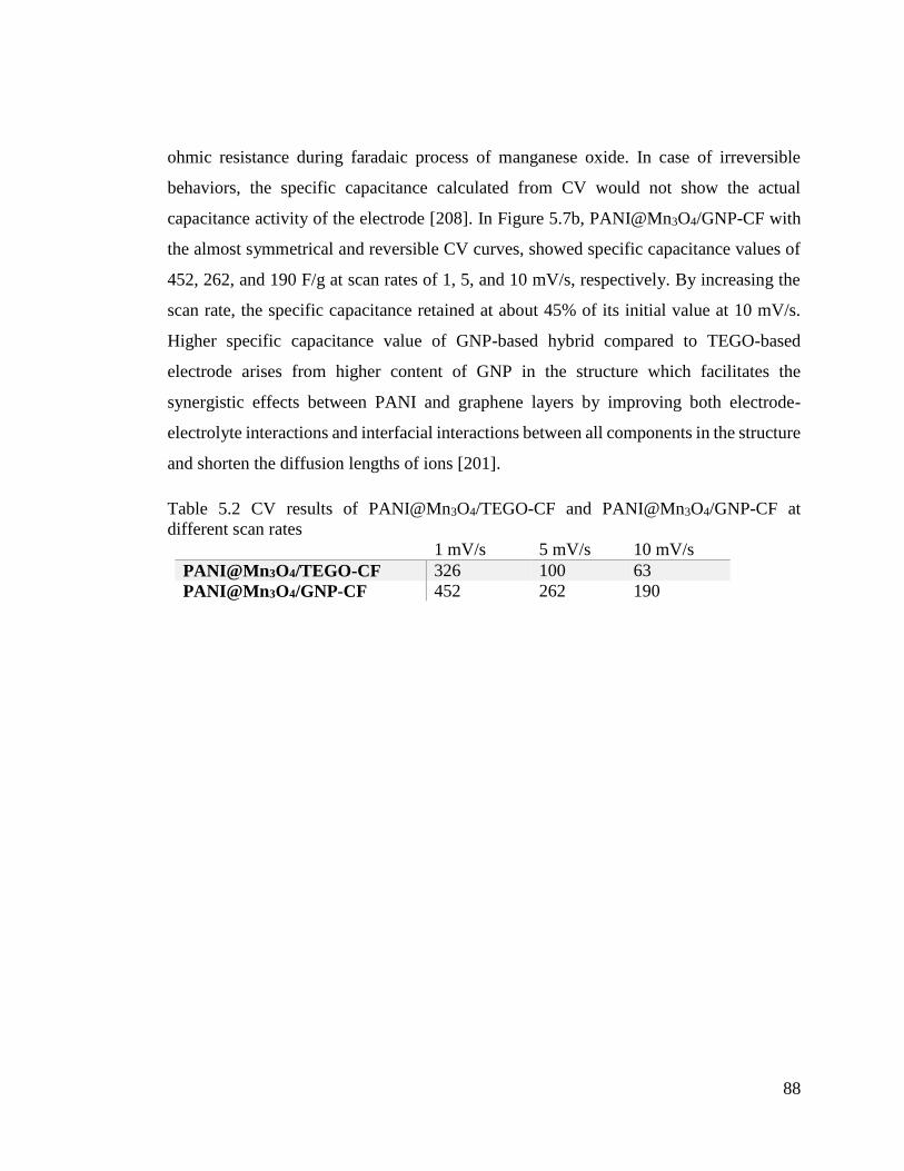
88
ohmic resistance during faradaic process of manganese oxide. In case of irreversible
behaviors, the specific capacitance calculated from CV would not show the actual
capacitance activity of the electrode [208]. In Figure 5.7b, PANI@Mn3O4/GNP-CF with
the almost symmetrical and reversible CV curves, showed specific capacitance values of
452, 262, and 190 F/g at scan rates of 1, 5, and 10 mV/s, respectively. By increasing the
scan rate, the specific capacitance retained at about 45% of its initial value at 10 mV/s.
Higher specific capacitance value of GNP-based hybrid compared to TEGO-based
electrode arises from higher content of GNP in the structure which facilitates the
synergistic effects between PANI and graphene layers by improving both electrode-
electrolyte interactions and interfacial interactions between all components in the structure
and shorten the diffusion lengths of ions [201].
Table 5.2 CV results of PANI@Mn3O4/TEGO-CF and PANI@Mn3O4/GNP-CF at
different scan rates
1 mV/s 5 mV/s 10 mV/s
PANI@Mn3O4/TEGO-CF 326 100 63
PANI@Mn3O4/GNP-CF 452 262 190

89
Figure 5.7 CV curves of (a) PANI@Mn3O4/TEGO-CF, (b) PANI@Mn3O4/GNP-CF at
different scan rates of 1, 5, and 10 mV/s, (c) specific capacitance of
PANI@Mn3O4/TEGO-CF and PANI@Mn3O4/GNP-CF at different scan rates and (d)
comparison of electrochemical performance of electrodes at 1 mV/s
The galvanostatic charge-discharge test (GCD) was performed to further evaluate
the electrochemical performance of fabricated electrodes. The GCD plots of both
electrodes exhibit almost triangular shapes shown in Figure 5.8a and Figure 5.8b.
However, in the case of PANI@Mn3O4/TEGO-CF electrode, there is a nonlinearity with
longer charging time rather than discharging time which is a reflection of quasi-reversible
electrode reaction [208]. During charging process, the irreversible electrochemical
polarization fasten the faradaic reduction of manganese oxide into soluble manganese ions
in electrolyte and thus decrease the discharging time [209].
0,0 0,2 0,4 0,6 0,8
-2
-1
0
1
2
Cu
rre
nt
De
ns
ity
(A
/g)
Voltage (V)
PANI@Mn3O
4/TEGO-CF
1 mV/s
5 mV/s
10 mV/s
0,0 0,2 0,4 0,6 0,8
-2
-1
0
1
2
Cu
rre
nt
De
ns
ity
(A
/g)
Voltage (V)
1 mV/s
5 mV/s
10 mV/s
PANI@Mn3O
4/GLS-CF
2 4 6 8 10
100
200
300
400
S
pe
cif
ic c
ap
acit
an
ce
(F
/g)
Scan rate (mV/s)
PANI@Mn3O
4/GLS-CF
PANI@Mn3O
4/TEGO-CF
0,0 0,2 0,4 0,6 0,8
-0,4
-0,2
0,0
0,2
0,4
Cu
rre
nt
De
ns
ity
(A
/g)
Voltage (V)
PANI@Mn3O
4/GLS-CF
PANI@Mn3O
4/TEGO-CF
1 mV/s
a b
c d
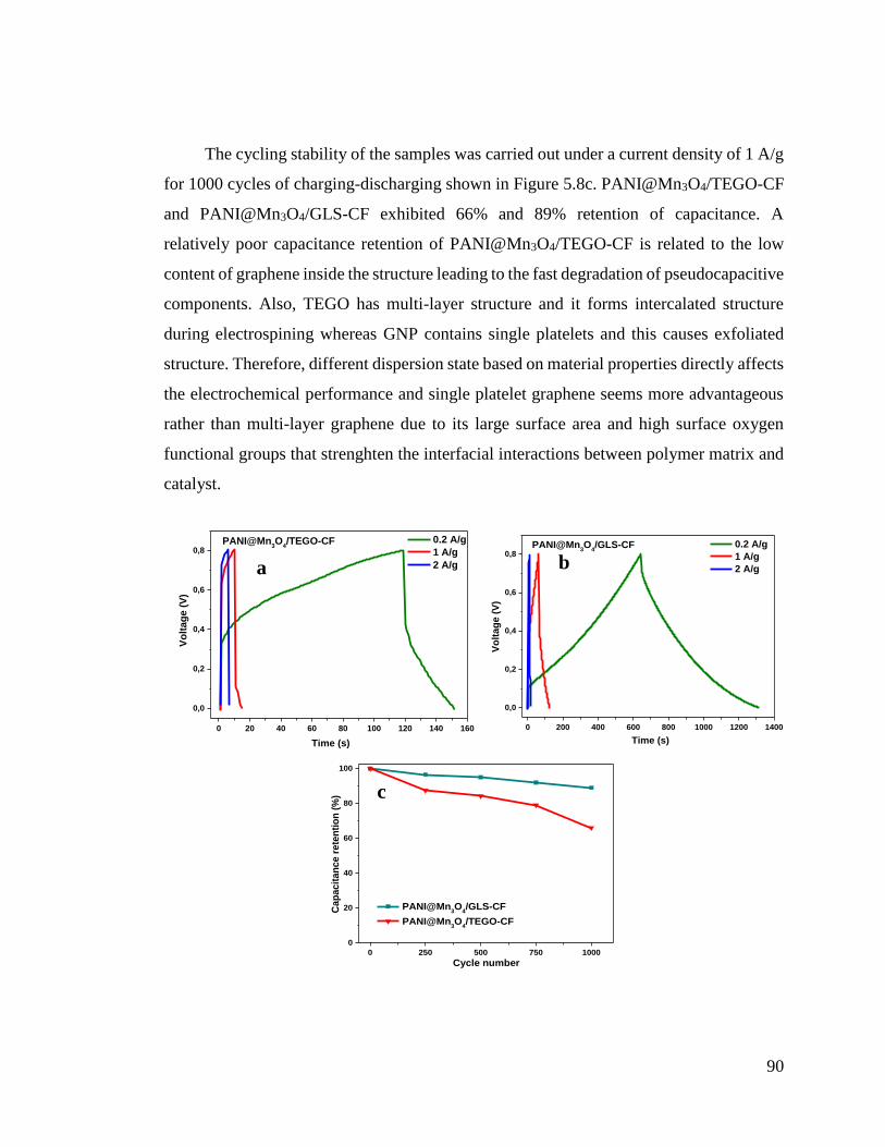
90
The cycling stability of the samples was carried out under a current density of 1 A/g
for 1000 cycles of charging-discharging shown in Figure 5.8c. PANI@Mn3O4/TEGO-CF
and PANI@Mn3O4/GLS-CF exhibited 66% and 89% retention of capacitance. A
relatively poor capacitance retention of PANI@Mn3O4/TEGO-CF is related to the low
content of graphene inside the structure leading to the fast degradation of pseudocapacitive
components. Also, TEGO has multi-layer structure and it forms intercalated structure
during electrospining whereas GNP contains single platelets and this causes exfoliated
structure. Therefore, different dispersion state based on material properties directly affects
the electrochemical performance and single platelet graphene seems more advantageous
rather than multi-layer graphene due to its large surface area and high surface oxygen
functional groups that strenghten the interfacial interactions between polymer matrix and
catalyst.
0 20 40 60 80 100 120 140 160
0,0
0,2
0,4
0,6
0,8
Time (s)
Vo
ltag
e (
V)
PANI@Mn3O
4/TEGO-CF 0.2 A/g
1 A/g
2 A/g
0 200 400 600 800 1000 1200 1400
0,0
0,2
0,4
0,6
0,8
Vo
ltag
e (
V)
Time (s)
PANI@Mn3O
4/GLS-CF
0.2 A/g
1 A/g
2 A/g
0 250 500 750 1000
0
20
40
60
80
100
Cap
acit
an
ce r
ete
nti
on
(%
)
Cycle number
PANI@Mn3O
4/GLS-CF
PANI@Mn3O
4/TEGO-CF
a b
c

91
Figure 5.8 GCD curves of (a) PANI@Mn3O4/TEGO-CF, (b) PANI@Mn3O4/GNP-CF at
current densities of 0.2, 1, and 2 A/g, and (c) cycling stability of upon charging-
discharging at a current density of 1 A/g.
Conclusions
In the present work, a series of PANI coated Mn3O4/graphene embedded carbon
fibers with different graphene sources were synthesized through core-shell
electrospinning, carbonization and in-situ polymerization techniques. Multi-layer
graphene and single platelets graphene were incorporated into the fiber structure and the
effect of number of graphene layers on the electrochemical performance of electrodes was
investigated by CV and GCD tests. The spectroscopy analysis confirmed the strong
interactions between the components of ternary hybrid composites. PANI coated
Mn3O4/GNP-CF exhibited a high specific capacitance of 452 F/g at a scan rate of 1 mV/s
and 89% capacitance retention after 1000 cycle of charging-discharging. The introduction
of graphene single platelets into the fiber structure facilitated both ion and electron
transport and provided highly electroactive sites and shortened the diffusion paths by
bridging the adjacent individual PANI chains. Additionally, relatively high oxygen
functional groups of GNP enhanced the interfacial interactions between electrode
components. On the other hand, PANI coated Mn3O4/TEGO-CF showed a specific
capacitance of 326 F/g at a scan rate of 1 mV/s with poor cycling stability of 66% after
1000 cycles of charge-discharge at a current density of 0.2 A/g. Low content of graphene
in the structure of PANI@Mn3O4/TEGO-CF caused a rapid polarization of manganese
oxide ions and thus irreversible reactions during charge-discharge fastened the
degradation of electrode. Consequently, the number of graphene layers, its surface oxygen
functional groups as well as its dispersion state greatly affected the electrochemical
performance of supercapacitor electrodes and these complex designed ternary hybrid
electrodes bring a new insight in fabrication of high performance energy storage devices.
92
CONCLUSIONS
This study was conducted in three major sections. The findings for each step can be
summarized as follows:
1) Design and fabrication of hollow and filled graphene-based polymeric spheres via
core-shell electrospraying:
Firstly, the effect of electric field on the exfoliation process of graphene sheets
during electrospraying was investigated in details. Electrospraying prevents the
agglomeration of graphene sheets by enhancing the intercalation of polymeric chains into
graphene sheets. Raman analysis showed that electrosprayed graphene preserves its multi-
layer nature.
In the next step, three-different types of polymers were used as spacers between the
graphene sheets by converting the 2D structure to different graphene-based architectures.
The proper polymer concentration for the formation of spherical particles was investigated
by using the Mark-Houwink-Sakurada equations. Three types of electrospun solutions
with different polymers were prepared and electrosprayed separately. The hollowness of
spheres was controlled by changing core solvent. Consequently, by tailoring process
parameters like voltage and flow rate and appropriate polymer concentration, graphene-
based polymeric spheres with desirable size and hollowness opens up new directions
especially in energy applications such as Li-ion batteries, fuel cells, and supercapacitors.
2) Design of Pt-supported 1D and 3D multilayer graphene-based structural composite
electrodes with controlled morphology by core-shell electrospinning/electrospraying
In this part of study, three different forms of Pt-decorated graphene based structures
with controlled dimensionality were successfully fabricated through core-shell
electrospraying/electrospinning approach. The proper polymer concentration for the
formation of three different structures of sphere, fibers, and foam was determined by using
Mark-Houwink-Sakurada equations. PAN polymer was used as a carrier during
electrospinning whereby, after applying heat treatment it carbonized to carbon. Platinum
was used as catalyst in order to increase the catalytic activity of composites. The
93
morphology and structural properties of composites were investigated via microscopic and
spectroscopic characterization techniques. Moreover, the electrochemical performance of
Pt-decorated graphene-based spheres, fibers, and foam was investigated through CV and
GCD methods. Among the three different electrodes, Pt-supported 3D graphene-based
spheres showed the highest specific capacitance of 118 F/g at a scan rate of 1 mV/s owing
to the homogeneous decoration of Pt particles with a small diameter of 4 nm on the surface.
After 1000 cycles of charging-discharging, Pt-decorated graphene-based structures
showed high cyclic stability, indicating their potential as high-performance electrodes for
energy storage devices.
3) Free-standing hierarchical hybrid electrodes based on PANI coated Mn3O4/graphene
embedded carbon fibers for high performance supercapacitors
In this study, a facile and straightforward route for the fabrication of hierarchical
PANI coated graphene and manganese oxide embedded in carbon fibers (CF) via core-
shell electrospinning has been reported. MnCl2 was used as manganese source, whereby
during heat treatment of PAN polymer, it oxidized to manganese oxide. Moreover, multi-
layer graphene and single platelets graphene were incorporated into the fiber structure
separately and the effect of number of graphene layers on the electrochemical performance
of electrodes was investigated by CV and GCD tests. PANI coated Mn3O4/GNP-CF
exhibited a high specific capacitance of 452 F/g at a scan rate of 1 mV/s and 89%
capacitance retention after 1000 cycle of charging-discharging. The introduction of
graphene single platelets into the fiber structure facilitated both ion and electron transport,
provided highly electroactive sites, and shortened the diffusion paths by bridging the
adjacent individual PANI chains. Consequently, the number of graphene layers, its surface
oxygen functional groups as well as its dispersion state greatly affected the
electrochemical performance of supercapacitor electrodes. Besides high electrochemical
performance, low manufacturing cost and processability are the main factors for the
utilization of these fabricated electrodes in the industrial applications. Especially use of
graphene obtained from waste sources would severely lower the cost of production.

94
Consequently, low cost and multi-functionalized graphene-based hybrid materials become
promising candidates in the energy storage devices.
In the future studies, the content of Mn3O4 in the structure will be optimized and the
interaction of PANI chains with graphene sheets will be improved by tailoring the
synthesis parameters in order to decrease the degradation period of hybrid electrodes. In
addition to fibers, Mn3O4 and polyaniline will be integrated into the graphene-based
spheres and foam to attain high surface area and porous structure through core-shell
electrospraying technique.

95
BIBLIOGRAPHY
[1] X. Du, I. Skachko, A. Barker, and E. Y. Andrei, “Approaching ballistic transport in
suspended graphene,” Nat. Nanotechnol., vol. 3, no. 8, pp. 491–495, Aug. 2008.
[2] A. A. Balandin, S. Ghosh, W. Bao, I. Calizo, D. Teweldebrhan, F. Miao, and C. N. Lau,
“Superior Thermal Conductivity of Single-Layer Graphene,” Nano Lett., vol. 8, no. 3, pp.
902–907, Mar. 2008.
[3] Y. Zhu, S. Murali, W. Cai, X. Li, J. W. Suk, J. R. Potts, and R. S. Ruoff, “Graphene and
graphene oxide: Synthesis, properties, and applications,” Adv. Mater., vol. 22, no. 35, pp.
3906–3924, 2010.
[4] A. E. Galashev and O. R. Rakhmanova, “Mechanical and thermal stability of graphene and
graphene-based materials,” Physics-Uspekhi, vol. 57, no. 10, pp. 970–989, 2014.
[5] C. Lee, X. Wei, J. W. Kysar, and J. Hone, “Measurement of the Elastic Properties and
Intrinsic Strength of Monolayer Graphene,” Science (80-. )., vol. 321, no. 5887, pp. 385–
388, Jul. 2008.
[6] S. Mao, G. Lu, and J. Chen, “Three-dimensional graphene-based composites for energy
applications,” Nanoscale, 2014.
[7] Y. Zhao, C. Jiang, C. Hu, Z. Dong, J. Xue, Y. Meng, N. Zheng, P. Chen, and L. Qu,
“Large-scale spinning assembly of neat, morphology-defined, graphene-based hollow
fibers,” ACS Nano, vol. 7, no. 3, pp. 2406–2412, 2013.
[8] L. Haghighi Poudeh, B. Saner Okan, J. Seyyed Monfared Zanjani, M. Yildiz, and Y. Z.
Menceloglu, “Design and Fabrication of Hollow and Filled Graphene-based Polymeric
Spheres via Core-Shell Electrospraying,” RSC Adv., vol. 5, pp. 91147–91157, 2015.
[9] K. M. Forward, A. Flores, and G. C. Rutledge, “Production of core/shell fibers by
electrospinning from a free surface,” Chem. Eng. Sci., vol. 104, pp. 250–259, Dec. 2013.
[10] J. S. M. Zanjani, B. Saner Okan, Y. Z. Menceloglu, and M. Yildiz, “Design and fabrication
of multi-walled hollow nanofibers by triaxial electrospinning as reinforcing agents in
nanocomposites,” J. Reinf. Plast. Compos. , vol. 34, no. 16, pp. 1273–1286, Aug. 2015.
[11] L. Lim, Y. Liu, W. Liu, R. Tjandra, L. Rasenthiram, Z. Chen, and A. Yu, “All-in-One
Graphene Based Composite Fiber: Toward Wearable Supercapacitor,” ACS Appl. Mater.
Interfaces, vol. 9, no. 45, pp. 39576–39583, 2017.
[12] Z. Wang, Q. Qin, W. Xu, J. Yan, and Y. Wu, “Long Cyclic Life in Manganese Oxide-
Based Electrodes,” ACS Appl. Mater. Interfaces, vol. 8, no. 28, pp. 18078–18088, 2016.
[13] K. S. Novoselov, A. K. Geim, S. V. Morozov, D. Jiang, Y. Zhang, S. V. Dubonos, I. V.
Grigorieva, and A. A. Firsov, “Electric field effect in atomically thin carbon films.,”
Science (80-. )., vol. 306, no. 5696, pp. 666–669, 2004.

96
[14] P. W. Sutter, J.-I. Flege, and E. A. Sutter, “Epitaxial graphene on ruthenium,” Nat. Mater.,
vol. 7, no. 5, pp. 406–411, May 2008.
[15] K. S. Kim, Y. Zhao, H. Jang, S. Y. Lee, J. M. Kim, K. S. Kim, J.-H. Ahn, P. Kim, J.-Y.
Choi, and B. H. Hong, “Large-scale pattern growth of graphene films for stretchable
transparent electrodes,” Nature, vol. 457, no. 7230, pp. 706–710, Feb. 2009.
[16] J. Lu, J. Yang, J. Wang, A. Lim, S. Wang, and K. P. Loh, “One-Pot Synthesis of
Fluorescent Carbon Nanoribbons, Nanoparticles, and Graphene by the Exfoliation of
Graphite in Ionic Liquids,” ACS Nano, vol. 3, no. 8, pp. 2367–2375, Aug. 2009.
[17] S. Stankovich, D. a. Dikin, R. D. Piner, K. a. Kohlhaas, A. Kleinhammes, Y. Jia, Y. Wu, S.
T. Nguyen, and R. S. Ruoff, “Synthesis of graphene-based nanosheets via chemical
reduction of exfoliated graphite oxide,” Carbon N. Y., vol. 45, pp. 1558–1565, 2007.
[18] S. Park and R. S. Ruoff, “Chemical methods for the production of graphenes.,” Nat.
Nanotechnol., vol. 4, no. march, pp. 217–224, 2009.
[19] C. Li and G. Shi, “Three-dimensional graphene architectures,” Nanoscale, vol. 4, no. 18, p.
5549, 2012.
[20] D. R. Dreyer, S. Park, C. W. Bielawski, and R. S. Ruoff, “The chemistry of graphene
oxide,” Chem. Soc. Rev., vol. 39, no. 1, pp. 228–240, 2010.
[21] M. Khan, M. N. Tahir, S. F. Adil, H. U. Khan, M. R. H. Siddiqui, A. A. Al-warthan, and
W. Tremel, “Graphene based metal and metal oxide nanocomposites: synthesis, properties
and their applications,” J. Mater. Chem. A, vol. 3, no. 37, pp. 18753–18808, 2015.
[22] B. C. Brodie, “On the Atomic Weight of Graphite,” Phil. Trans. R. Soc. Lond., vol. 149,
no. January, pp. 249–259, 1859.
[23] L. Staudenmaier, “Verfahren zur Darstellung der Graphitsaure,” Ber Dtsch Chem Ges, vol.
31, pp. 1481–1487, 1898.
[24] J. William S. Hummers and R. E. Offeman, “Preparation of Graphitic Oxide,” J. Am.
Chem. Soc, vol. 80, no. 1937, p. 1339, 1958.
[25] J. Chen, B. Yao, C. Li, and G. Shi, “An improved Hummers method for eco-friendly
synthesis of graphene oxide,” Carbon N. Y., vol. 64, no. 1, pp. 225–229, 2013.
[26] D. C. Marcano, D. V. Kosynkin, J. M. Berlin, A. Sinitskii, Z. Sun, A. Slesarev, L. B.
Alemany, W. Lu, and J. M. Tour, “Improved synthesis of graphene oxide,” ACS Nano, vol.
4, no. 8, pp. 4806–4814, 2010.
[27] B. Saner, F. Okyay, and Y. Yürüm, “Utilization of multiple graphene layers in fuel cells. 1.
An improved technique for the exfoliation of graphene-based nanosheets from graphite,”
Fuel, vol. 89, no. 8, pp. 1903–1910, 2010.

97
[28] M. J. McAllister, J.-L. Li, D. H. Adamson, H. C. Schniepp, A. A. Abdala, J. Liu, M.
Herrera-Alonso, D. L. Milius, R. Car, R. K. Prud’homme, and I. A. Aksay, “Single Sheet
Functionalized Graphene by Oxidation and Thermal Expansion of Graphite,” Chem.
Mater., vol. 19, no. 18, pp. 4396–4404, Sep. 2007.
[29] S. Stankovich, D. A. Dikin, R. D. Piner, K. A. Kohlhaas, A. Kleinhammes, Y. Jia, Y. Wu,
S. T. Nguyen, and R. S. Ruoff, “Synthesis of graphene-based nanosheets via chemical
reduction of exfoliated graphite oxide,” Carbon N. Y., vol. 45, no. 7, pp. 1558–1565, Jun.
2007.
[30] B. Saner, F. Dinç, and Y. Yürüm, “Utilization of multiple graphene nanosheets in fuel
cells: 2. the effect of oxidation process on the characteristics of graphene nanosheets,”
Fuel, vol. 90, no. 8, pp. 2609–2616, 2011.
[31] Y. Si and E. T. Samulski, “Synthesis of water soluble graphene,” Nano Lett., vol. 8, pp.
1679–82, 2008.
[32] Y. Xu, K. Sheng, C. Li, and G. Shi, “Self-Assembled Graphene Hydrogel via a One-Step
Hydrothermal Process,” ACS Nano, vol. 4, no. 7, pp. 4324–4330, Jul. 2010.
[33] J. Kim, L. J. Cote, F. Kim, W. Yuan, K. R. Shull, and J. Huang, “Graphene Oxide Sheets
at Interfaces,” J. Am. Chem. Soc., vol. 132, no. 23, pp. 8180–8186, Jun. 2010.
[34] H. Bai, C. Li, X. Wang, and G. Shi, “On the gelation of graphene oxide,” J. Phys. Chem.
C, vol. 115, no. 13, pp. 5545–5551, 2011.
[35] V. H. Luan, H. N. Tien, L. T. Hoa, N. T. M. Hien, E.-S. Oh, J. Chung, E. J. Kim, W. M.
Choi, B.-S. Kong, and S. H. Hur, “Synthesis of a highly conductive and large surface area
graphene oxide hydrogel and its use in a supercapacitor,” J. Mater. Chem. A, vol. 1, no. 2,
pp. 208–211, 2013.
[36] D. Wang, R. Kou, D. Choi, Z. Yang, Z. Nie, J. Li, L. V. Saraf, D. Hu, J. Zhang, G. L.
Graff, J. Liu, M. A. Pope, and I. A. Aksay, “Ternary Self-Assembly of Ordered Metal
Oxide−Graphene Nanocomposites for Electrochemical Energy Storage,” ACS Nano, vol.
4, no. 3, pp. 1587–1595, Mar. 2010.
[37] A. J. Patil, J. L. Vickery, T. B. Scott, and S. Mann, “Aqueous Stabilization and Self-
Assembly of Graphene Sheets into Layered Bio-Nanocomposites using DNA,” Adv.
Mater., vol. 21, no. 31, pp. 3159–3164, Aug. 2009.
[38] G. Eda and M. Chhowalla, “Chemically Derived Graphene Oxide: Towards Large-Area
Thin-Film Electronics and Optoelectronics,” Adv. Mater., vol. 22, no. 22, pp. 2392–2415,
Jun. 2010.
[39] M. Zeng, W. L. Wang, and X. D. Bai, “Preparing three-dimensional graphene
architectures: Review of recent developments,” Chinese Phys. B, vol. 22, no. 9, 2013.
[40] X. Cao, Z. Yin, and H. Zhang, “Three-dimensional graphene materials: preparation,
98
structures and application in supercapacitors,” Energy Environ. Sci., vol. 7, p. 1850, 2014.
[41] X. Ji, X. Zhang, and X. Zhang, “Three-Dimensional Graphene-Based Nanomaterials as
Electrocatalysts for Oxygen Reduction Reaction,” J. Nanomater., vol. 2015, pp. 1–9, 2015.
[42] O. C. Compton, Z. An, K. W. Putz, B. J. Hong, B. G. Hauser, L. Catherine Brinson, and S.
T. Nguyen, “Additive-free hydrogelation of graphene oxide by ultrasonication,” Carbon N.
Y., vol. 50, no. 10, pp. 3399–3406, Aug. 2012.
[43] H. Bai, C. Li, X. Wang, and G. Shi, “A pH-sensitive graphene oxide composite hydrogel,”
Chem. Commun., vol. 46, no. 14, p. 2376, 2010.
[44] Y. Xu, Q. Wu, Y. Sun, H. Bai, and G. Shi, “Three-Dimensional Self-Assembly of
Graphene Oxide and DNA into Multifunctional Hydrogels,” ACS Nano, vol. 4, no. 12, pp.
7358–7362, Dec. 2010.
[45] H. P. Cong, X. C. Ren, P. Wang, and S. H. Yu, “Macroscopic multifunctional graphene-
based hydrogels and aerogels by a metal ion induced self-assembly process,” ACS Nano,
vol. 6, no. 3, pp. 2693–2703, 2012.
[46] W. Chen, S. Li, C. Chen, and L. Yan, “Self-Assembly and Embedding of Nanoparticles by
In Situ Reduced Graphene for Preparation of a 3D Graphene/Nanoparticle Aerogel,” Adv.
Mater., vol. 23, no. 47, pp. 5679–5683, Dec. 2011.
[47] G. He, H. Tang, H. Wang, and Z. Bian, “Highly Selective and Active Pd-In/three-
dimensional Graphene with Special Structure for Electroreduction CO 2 to Formate,”
Electroanalysis, pp. 1–11, 2017.
[48] Y. Ma and Y. Chen, “Three-dimensional graphene networks: synthesis, properties and
applications,” Natl. Sci. Rev., vol. 2, pp. 40–53, 2014.
[49] X. Xie, Y. Zhou, H. Bi, K. Yin, S. Wan, and L. Sun, “Large-range control of the
microstructures and properties of three-dimensional porous graphene,” Sci. Rep., vol. 3,
pp. 1–6, 2013.
[50] K. Sheng, Y. Sun, C. Li, W. Yuan, and G. Shi, “Ultrahigh-rate supercapacitors based on
eletrochemically reduced graphene oxide for ac line-filtering,” Sci. Rep., vol. 2, no. 1, p.
247, Dec. 2012.
[51] K. Chen, L. Chen, Y. Chen, H. Bai, and L. Li, “Three-dimensional porous graphene-based
composite materials: electrochemical synthesis and application,” J. Mater. Chem., vol. 22,
no. 39, p. 20968, 2012.
[52] J. Zhang, Y. Yu, L. Liu, and Y. Wu, “Graphene-hollow PPy sphere 3D-nanoarchitecture
with enhanced electrochemical performance.,” Nanoscale, vol. 5, no. 7, pp. 3052–7, 2013.
[53] D. Cai, L. Ding, S. Wang, Z. Li, M. Zhu, and H. Wang, “Facile synthesis of ultrathin-shell
graphene hollow spheres for high-performance lithium-ion batteries,” Electrochim. Acta,

99
vol. 139, pp. 96–103, 2014.
[54] Q. Shao, J. Tang, Y. Lin, F. Zhang, J. Yuan, H. Zhang, N. Shinya, and L.-C. Qin,
“Synthesis and characterization of graphene hollow spheres for application in
supercapacitors,” J. Mater. Chem. A, vol. 1, pp. 15423–15428, 2013.
[55] L. Wu, H. Feng, M. Liu, K. Zhang, and J. Li, “Graphene-based hollow spheres as efficient
electrocatalysts for oxygen reduction.,” Nanoscale, vol. 5, pp. 10839–43, 2013.
[56] X. Huang, K. Qian, J. Yang, J. Zhang, L. Li, C. Yu, and D. Zhao, “Functional nanoporous
graphene foams with controlled pore sizes,” Adv. Mater., vol. 24, no. 32, pp. 4419–4423,
2012.
[57] J. Seyyed Monfared Zanjani, B. Saner Okan, I. Letofsky-Papst, M. Yildiz, and Y. Z.
Menceloglu, “Rational design and direct fabrication of multi-walled hollow electrospun
fibers with controllable structure and surface properties,” Eur. Polym. J., vol. 62, pp. 66–
76, 2015.
[58] S. Shilpa, B. M. Basavaraja, S. B. Majumder, and A. Sharma, “Electrospun hollow glassy
carbon–reduced graphene oxide nanofibers with encapsulated ZnO nanoparticles: a free
standing anode for Li-ion batteries,” J. Mater. Chem. A, vol. 3, no. 10, pp. 5344–5351,
2015.
[59] C.-J. Lin, C.-L. Liu, and W.-C. Chen, “Poly(3-hexylthiophene)/Graphene Composites
based Aligned Nanofibers for High Performance Field Effect Transistors,” J. Mater. Chem.
C, 2015.
[60] N. Promphet, P. Rattanarat, R. Rangkupan, O. Chailapakul, and N. Rodthongkum, “An
electrochemical sensor based on graphene/polyaniline/polystyrene nanoporous fibers
modified electrode for simultaneous determination of lead and cadmium,” Sensors
Actuators B Chem., vol. 207, pp. 526–534, Feb. 2015.
[61] M. J. Allen, V. C. Tung, and R. B. Kaner, “Honeycomb carbon: A review of graphene,”
Chem. Rev., vol. 110, no. 1, pp. 132–145, 2010.
[62] Z. Chen, W. Ren, L. Gao, B. Liu, S. Pei, and H.-M. Cheng, “Three-dimensional flexible
and conductive interconnected graphene networks grown by chemical vapour deposition.,”
Nat. Mater., vol. 10, no. 6, pp. 424–428, 2011.
[63] O. Bagoole, M. Rahman, H. Younes, S. Shah, and A. Al Ghaferi, “Three-Dimensional
Graphene Interconnected Structure, Fabrication Methods and Applications: Review,” J.
Nanomed. Nanotechnol., vol. 8, no. 2, 2017.
[64] M. Zhou, T. Lin, F. Huang, Y. Zhong, Z. Wang, Y. Tang, H. Bi, D. Wan, and J. Lin,
“Highly Conductive Porous Graphene/Ceramic Composites for Heat Transfer and Thermal
Energy Storage,” Adv. Funct. Mater., vol. 23, no. 18, pp. 2263–2269, May 2013.
[65] G. Ning, Z. Fan, G. Wang, J. Gao, W. Qian, and F. Wei, “Gram-scale synthesis of
100
nanomesh graphene with high surface area and its application in supercapacitor
electrodes,” Chem. Commun., vol. 47, no. 21, p. 5976, 2011.
[66] W. Li, S. Gao, L. Wu, S. Qiu, Y. Guo, X. Geng, M. Chen, S. Liao, C. Zhu, Y. Gong, M.
Long, J. Xu, X. Wei, M. Sun, and L. Liu, “High-Density Three-Dimension Graphene
Macroscopic Objects for High-Capacity Removal of Heavy Metal Ions,” Sci. Rep., vol. 3,
no. 1, p. 2125, Dec. 2013.
[67] J.-S. Lee, H.-J. Ahn, J.-C. Yoon, and J.-H. Jang, “Three-dimensional nano-foam of few-
layer graphene grown by CVD for DSSC,” Phys. Chem. Chem. Phys., vol. 14, no. 22, p.
7938, 2012.
[68] Y. Ito, Y. Tanabe, H. J. Qiu, K. Sugawara, S. Heguri, N. H. Tu, K. K. Huynh, T. Fujita, T.
Takahashi, K. Tanigaki, and M. Chen, “High-quality three-dimensional nanoporous
graphene,” Angew. Chemie - Int. Ed., vol. 53, no. 19, pp. 4822–4826, 2014.
[69] S. Mao, K. Yu, J. Chang, D. A. Steeber, L. E. Ocola, and J. Chen, “Direct growth of
vertically-oriented graphene for field-effect transistor biosensor,” Sci. Rep., vol. 3, pp. 33–
36, 2013.
[70] H. Wang, L. Shi, T. Yan, J. Zhang, Q. Zhong, and D. Zhang, “Design of graphene-coated
hollow mesoporous carbon spheres as high performance electrodes for capacitive
deionization,” J. Mater. Chem. A, vol. 2, pp. 4739–4750, 2014.
[71] J. Luo, Q. Ma, H. Gu, Y. Zheng, and X. Liu, “Three-dimensional graphene-polyaniline
hybrid hollow spheres by layer-by-layer assembly for application in supercapacitor,”
Electrochim. Acta, vol. 173, pp. 184–192, 2015.
[72] S. Mao, Z. Wen, H. Kim, G. Lu, P. Hurley, and J. Chen, “A general approach to one-pot
fabrication of crumpled graphene-based nanohybrids for energy applications,” ACS Nano,
vol. 6, no. 8, pp. 7505–7513, 2012.
[73] J. S. Lee, S. I. Kim, J. C. Yoon, and J. H. Jang, “Chemical vapor deposition of mesoporous
graphene nanoballs for supercapacitor,” ACS Nano, vol. 7, no. 7, pp. 6047–6055, 2013.
[74] X. Huang, K. Qian, J. Yang, J. Zhang, L. Li, C. Yu, and D. Zhao, “Functional Nanoporous
Graphene Foams with Controlled Pore Sizes,” Adv. Mater., vol. 24, no. 32, pp. 4419–4423,
Aug. 2012.
[75] H. S. Ahn, J. M. Kim, C. Park, J.-W. Jang, J. S. Lee, H. Kim, M. Kaviany, and M. H. Kim,
“A Novel Role of Three Dimensional Graphene Foam to Prevent Heater Failure during
Boiling,” Sci. Rep., vol. 3, no. 1, p. 1960, Dec. 2013.
[76] H. Gao, F. Xiao, C. B. Ching, and H. Duan, “High-Performance Asymmetric
Supercapacitor Based on Graphene Hydrogel and Nanostructured MnO 2,” ACS Appl.
Mater. Interfaces, vol. 4, no. 5, pp. 2801–2810, May 2012.
[77] P. Chen, J.-J. Yang, S.-S. Li, Z. Wang, T.-Y. Xiao, Y.-H. Qian, and S.-H. Yu,

101
“Hydrothermal synthesis of macroscopic nitrogen-doped graphene hydrogels for ultrafast
supercapacitor,” Nano Energy, vol. 2, no. 2, pp. 249–256, Mar. 2013.
[78] Z. Han, Z. Tang, P. Li, G. Yang, Q. Zheng, and J. Yang, “Ammonia solution strengthened
three-dimensional macro-porous graphene aerogel,” Nanoscale, vol. 5, no. 12, p. 5462,
2013.
[79] H. Sun, Z. Xu, and C. Gao, “Multifunctional, Ultra-Flyweight, Synergistically Assembled
Carbon Aerogels,” Adv. Mater., vol. 25, no. 18, pp. 2554–2560, May 2013.
[80] Z. Xu, Z. Li, C. M. B. Holt, X. Tan, H. Wang, B. S. Amirkhiz, T. Stephenson, and D.
Mitlin, “Electrochemical Supercapacitor Electrodes from Sponge-like Graphene
Nanoarchitectures with Ultrahigh Power Density,” J. Phys. Chem. Lett., vol. 3, no. 20, pp.
2928–2933, Oct. 2012.
[81] H.-B. Yao, J. Ge, C.-F. Wang, X. Wang, W. Hu, Z.-J. Zheng, Y. Ni, and S.-H. Yu, “A
Flexible and Highly Pressure-Sensitive Graphene-Polyurethane Sponge Based on
Fractured Microstructure Design,” Adv. Mater., vol. 25, no. 46, pp. 6692–6698, Dec. 2013.
[82] X. Cao, Y. Shi, W. Shi, G. Lu, X. Huang, Q. Yan, Q. Zhang, and H. Zhang, “Preparation
of novel 3D graphene networks for supercapacitor applications,” Small, vol. 7, no. 22, pp.
3163–3168, 2011.
[83] A. C. Ferrari, J. C. Meyer, V. Scardaci, C. Casiraghi, M. Lazzeri, F. Mauri, S. Piscanec, D.
Jiang, K. S. Novoselov, S. Roth, and A. K. Geim, “Raman spectrum of graphene and
graphene layers,” Phys. Rev. Lett., vol. 97, p. 187401, 2006.
[84] W. Li, S. Gao, L. Wu, S. Qiu, Y. Guo, X. Geng, M. Chen, S. Liao, C. Zhu, Y. Gong, M.
Long, J. Xu, X. Wei, M. Sun, and L. Liu, “High-density three-dimension graphene
macroscopic objects for high-capacity removal of heavy metal ions.,” Sci. Rep., vol. 3, p.
2125, 2013.
[85] Z. Y. Sui, Y. Cui, J. H. Zhu, and B. H. Han, “Preparation of Three-dimensional graphene
oxide-polyethylenimine porous materials as dye and gas adsorbents,” ACS Appl. Mater.
Interfaces, vol. 5, no. 18, pp. 9172–9179, 2013.
[86] H. Bin Yao, J. Ge, C. F. Wang, X. Wang, W. Hu, Z. J. Zheng, Y. Ni, and S. H. Yu, “A
flexible and highly pressure-sensitive graphene-polyurethane sponge based on fractured
microstructure design,” Adv. Mater., vol. 25, no. 46, pp. 6692–6698, 2013.
[87] Y. Shao, M. F. El-Kady, C. W. Lin, G. Zhu, K. L. Marsh, J. Y. Hwang, Q. Zhang, Y. Li,
H. Wang, and R. B. Kaner, “3D Freeze-Casting of Cellular Graphene Films for Ultrahigh-
Power-Density Supercapacitors,” Adv. Mater., pp. 6719–6726, 2016.
[88] X. Yang, J. Zhu, L. Qiu, and D. Li, “Bioinspired effective prevention of restacking in
multilayered graphene films: Towards the next generation of high-performance
supercapacitors,” Adv. Mater., vol. 23, no. 25, pp. 2833–2838, 2011.

102
[89] Q. Wu, Y. Xu, Z. Yao, A. Liu, and G. Shi, “Supercapacitors Based on Flexible
Graphene/Polyaniline Nanofiber Composite Films,” ACS Nano, vol. 4, no. 4, pp. 1963–
1970, 2010.
[90] C. Tan, X. Huang, and H. Zhang, “Synthesis and applications of graphene-based noble
metal nanostructures,” Mater. Today, vol. 16, no. 1–2, pp. 29–36, Jan. 2013.
[91] W. Shi, J. Zhu, D. H. Sim, Y. Y. Tay, Z. Lu, X. Zhang, Y. Sharma, M. Srinivasan, H.
Zhang, H. H. Hng, and Q. Yan, “Achieving high specific charge capacitances in
Fe3O4/reduced graphene oxide nanocomposites,” J. Mater. Chem., vol. 21, no. 10, p.
3422, 2011.
[92] Q. Cheng, J. Tang, N. Shinya, and L. C. Qin, “Co(OH)2nanosheet-decorated graphene-
CNT composite for supercapacitors of high energy density,” Sci. Technol. Adv. Mater.,
vol. 15, no. 1, 2014.
[93] M. Li, Z. Tang, M. Leng, and J. Xue, “Flexible solid-state supercapacitor based on
graphene-based hybrid films,” Adv. Funct. Mater., vol. 24, no. 47, pp. 7495–7502, 2014.
[94] M. Jahan, Q. Bao, and K. P. Loh, “Electrocatalytically Active Graphene − Porphyrin MOF
Composite for Oxygen Reduction Reaction,” J. Am. Chem. Soc., vol. 134, no. 15, pp.
6707–6713, 2012.
[95] B. G. Choi, M. Yang, W. H. Hong, J. W. Choi, and Y. S. Huh, “3D macroporous graphene
frameworks for supercapacitors with high energy and power densities,” ACS Nano, vol. 6,
no. 5, pp. 4020–4028, 2012.
[96] S. Korkut, J. D. Roy-Mayhew, D. M. Dabbs, D. L. Milius, and I. A. Aksay, “High Surface
Area Tapes Produced with Functionalized Graphene,” ACS Nano, vol. 5, no. 6, pp. 5214–
5222, Jun. 2011.
[97] Z. Niu, J. Chen, H. H. Hng, J. Ma, and X. Chen, “A Leavening Strategy to Prepare
Reduced Graphene Oxide Foams,” Adv. Mater., vol. 24, no. 30, pp. 4144–4150, Aug.
2012.
[98] M. F. El-Kady, V. Strong, S. Dubin, and R. B. Kaner, “Laser Scribing of High-
Performance and Flexible Graphene-Based Electrochemical Capacitors,” Science (80-. ).,
vol. 335, no. 6074, pp. 1326–1330, Mar. 2012.
[99] L. Zhang, F. Zhang, X. Yang, G. Long, Y. Wu, T. Zhang, K. Leng, Y. Huang, Y. Ma, A.
Yu, and Y. Chen, “Porous 3D graphene-based bulk materials with exceptional high surface
area and excellent conductivity for supercapacitors,” Sci. Rep., vol. 3, no. 1, p. 1408, Dec.
2013.
[100] Y. Zhang, P. Chen, X. Gao, B. Wang, H. Liu, H. Wu, H. Liu, and S. Dou, “Nitrogen-
Doped Graphene Ribbon Assembled Core–Sheath MnO@Graphene Scrolls as
Hierarchically Ordered 3D Porous Electrodes for Fast and Durable Lithium Storage,” Adv.
Funct. Mater., vol. 26, no. 43, pp. 7754–7765, 2016.
103
[101] C. Hu, Y. Zhao, H. Cheng, Y. Wang, Z. Dong, C. Jiang, X. Zhai, L. Jiang, and L. Qu,
“Graphene microtubings: Controlled fabrication and site-specific functionalization,” Nano
Lett., vol. 12, pp. 5879–5884, 2012.
[102] X. Wei, Y. Li, W. Xu, K. Zhang, J. Yin, S. Shi, J. Wei, F. Di, J. Guo, C. Wang, C. Chu, N.
Sui, B. Chen, Y. Zhang, H. Hao, X. Zhang, J. Zhao, H. Zhou, and S. Wang, “From two-
dimensional graphene oxide to three-dimensional honeycomb-like Ni3S2@graphene oxide
composite: Insight into structure and electrocatalytic properties,” R. Soc. Open Sci., vol. 4,
no. 12, p. 171409, 2017.
[103] H. Wang, K. Sun, F. Tao, D. J. Stacchiola, and Y. H. Hu, “3D honeycomb-like structured
graphene and its high efficiency as a counter-electrode catalyst for dye-sensitized solar
cells,” Angew. Chemie - Int. Ed., vol. 52, no. 35, pp. 9210–9214, 2013.
[104] G. Wang, L. Zhang, and J. Zhang, “A review of electrode materials for electrochemical
supercapacitors,” Chem. Soc. Rev., vol. 41, no. 2, pp. 797–828, 2012.
[105] A. G. Pandolfo and A. F. Hollenkamp, “Carbon properties and their role in
supercapacitors,” J. Power Sources, vol. 157, no. 1, pp. 11–27, 2006.
[106] Q. Ke and J. Wang, “Graphene-based Materials for Supercapacitor Electrodes - A
Review,” J. Mater., vol. 2, no. 1, pp. 37–54, 2016.
[107] K. Qin, E. Liu, J. Li, J. Kang, C. Shi, C. He, F. He, and N. Zhao, “Free-Standing 3D
Nanoporous Duct-Like and Hierarchical Nanoporous Graphene Films for Micron-Level
Flexible Solid-State Asymmetric Supercapacitors,” Adv. Energy Mater., p. 1600755, 2016.
[108] W. Fan, Y. Y. Xia, W. W. Tjiu, P. K. Pallathadka, C. He, and T. Liu, “Nitrogen-doped
graphene hollow nanospheres as novel electrode materials for supercapacitor applications,”
J. Power Sources, vol. 243, pp. 973–981, 2013.
[109] W. Fan, C. Zhang, W. W. Tjiu, K. P. Pramoda, C. He, and T. Liu, “Graphene-Wrapped
Polyaniline Hollow Spheres As Novel Hybrid Electrode Materials for Supercapacitor
Applications,” ACS Appl. Mater. Interfaces, vol. 5, no. 8, pp. 3382–3391, Apr. 2013.
[110] Z. Yan, W. Yao, L. Hu, D. Liu, C. Wang, and C.-S. Lee, “Progress in the preparation and
application of three-dimensional graphene-based porous nanocomposites,” Nanoscale, vol.
7, no. 13, pp. 5563–5577, 2015.
[111] Y. Xu, Z. Lin, X. Huang, Y. Liu, Y. Huang, and X. Duan, “Flexible solid-state
supercapacitors based on three-dimensional graphene hydrogel films,” ACS Nano, vol. 7,
no. 5, pp. 4042–4049, 2013.
[112] Y. He, W. Chen, X. Li, Z. Zhang, J. Fu, C. Zhao, and E. Xie, “Freestanding three-
dimensional graphene/Mno2 composite networks as ultralight and flexible supercapacitor
electrodes,” ACS Nano, vol. 7, no. 1, pp. 174–182, 2013.
[113] C. Wang, Y. Li, Y.-S. Chui, Q.-H. Wu, X. Chen, and W. Zhang, “Three-dimensional Sn–

104
graphene anode for high-performance lithium-ion batteries,” Nanoscale, vol. 5, no. 21, p.
10599, 2013.
[114] L. Chu, M. Li, Y. Wang, X. Li, Z. Wan, S. Dou, and Y. Chu, “Multishelled NiO Hollow
Spheres Decorated by Graphene Nanosheets as Anodes for Lithium-Ion Batteries with
Improved Reversible Capacity and Cycling Stability,” J. Nanomater., vol. 2016, 2016.
[115] J. Luo, J. Liu, Z. Zeng, C. F. Ng, L. Ma, H. Zhang, J. Lin, Z. Shen, and H. J. Fan, “Three-
dimensional graphene foam supported Fe3O4 lithium battery anodes with long cycle life
and high rate capability,” Nano Lett., vol. 13, no. 12, pp. 6136–6143, 2013.
[116] Y. Tang, F. Huang, H. Bi, Z. Liu, and D. Wan, “Highly conductive three-dimensional
graphene for enhancing the rate performance of LiFePO 4 cathode,” J. Power Sources, vol.
203, pp. 130–134, 2012.
[117] S. H. Bae, K. Karthikeyan, Y. S. Lee, and I. K. Oh, “Microwave self-assembly of 3D
graphene-carbon nanotube-nickel nanostructure for high capacity anode material in lithium
ion battery,” Carbon N. Y., vol. 64, pp. 527–536, 2013.
[118] S. X. Yu, L. W. Yang, Y. Tian, P. Yang, F. Jiang, S. W. Hu, X. L. Wei, and J. X. Zhong,
“Mesoporous anatase TiO2 submicrospheres embedded in self-assembled three-
dimensional reduced graphene oxide networks for enhanced lithium storage,” J. Mater.
Chem. A, vol. 1, no. 41, p. 12750, 2013.
[119] W. Yang, K. R. Ratinac, S. P. Ringer, P. Thordarson, J. J. Gooding, and F. Braet, “Carbon
Nanomaterials in Biosensors: Should You Use Nanotubes or Graphene?,” Angew. Chemie
Int. Ed., vol. 49, no. 12, pp. 2114–2138, Mar. 2010.
[120] F. Yavari, Z. Chen, A. V. Thomas, W. Ren, H. M. Cheng, and N. Koratkar, “High
sensitivity gas detection using a macroscopic three-dimensional graphene foam network,”
Sci. Rep., vol. 1, pp. 1–5, 2011.
[121] C. C. Kung, P. Y. Lin, F. J. Buse, Y. Xue, X. Yu, L. Dai, and C. C. Liu, “Preparation and
characterization of three dimensional graphene foam supported platinum-ruthenium
bimetallic nanocatalysts for hydrogen peroxide based electrochemical biosensors,”
Biosens. Bioelectron., vol. 52, pp. 1–7, 2014.
[122] T. Yang, Q. Guan, Q. H. Li, L. Meng, L. L. Wang, C. X. Liu, and K. Jiao, “Large-area,
three-dimensional interconnected graphene oxide intercalated with self-doped polyaniline
nanofibers as a free-standing electrocatalytic platform for adenine and guanine,” J. Mater.
Chem. B, vol. 1, no. 23, pp. 2926–2933, 2013.
[123] H. Wang, G. Wang, Y. Ling, F. Qian, Y. Song, X. Lu, S. Chen, Y. Tong, and Y. Li, “High
power density microbial fuel cell with flexible 3D graphene–nickel foam as anode,”
Nanoscale, vol. 5, no. 21, p. 10283, 2013.
[124] Y. C. Yong, X. C. Dong, M. B. Chan-Park, H. Song, and P. Chen, “Macroporous and
monolithic anode based on polyaniline hybridized three-dimensional Graphene for high-

105
performance microbial fuel cells,” ACS Nano, vol. 6, no. 3, pp. 2394–2400, 2012.
[125] S. Zhao, Y. Li, H. Yin, Z. Liu, E. Luan, F. Zhao, Z. Tang, and S. Liu, “Three-dimensional
graphene/Pt nanoparticle composites as freestanding anode for enhancing performance of
microbial fuel cells,” Sci. Adv., vol. 1, no. 10, pp. e1500372–e1500372, 2015.
[126] T. Kuilla, S. Bhadra, D. Yao, N. H. Kim, S. Bose, and J. H. Lee, “Recent advances in
graphene based polymer composites,” Prog. Polym. Sci., vol. 35, no. 11, pp. 1350–1375,
2010.
[127] B. Luo, S. Liu, and L. Zhi, “Chemical approaches toward graphene-based nanomaterials
and their applications in energy-related areas,” Small, vol. 8, no. Xx, pp. 630–646, 2012.
[128] K. Coleman and R. S. Edwards, “Graphene synthesis: Relationship to applications,”
Nanoscale, pp. 38–51, 2012.
[129] Z. Zhang, F. Xiao, and S. Wang, “Hierarchically structured MnO 2 /graphene/carbon fiber
and porous graphene hydrogel wrapped copper wire for fiber-based flexible all-solid-state
asymmetric supercapacitors,” J. Mater. Chem. A, vol. 3, no. 21, pp. 11215–11223, 2015.
[130] J. S. Lee, S. I. Kim, J. C. Yoon, and J. H. Jang, “Chemical vapor deposition of mesoporous
graphene nanoballs for supercapacitor,” ACS Nano, vol. 7, no. 7, pp. 6047–6055, 2013.
[131] Z. Zhang, F. Xiao, L. Qian, J. Xiao, S. Wang, and Y. Liu, “Facile Synthesis of 3D MnO 2 -
Graphene and Carbon Nanotube-Graphene Composite Networks for High-Performance,
Flexible, All-Solid-State Asymmetric Supercapacitors,” Adv. Energy Mater., vol. 4, no. 10,
p. n/a-n/a, 2014.
[132] Z. Liu, Z. Tu, Y. Li, F. Yang, S. Han, W. Yang, L. Zhang, G. Wang, C. Xu, and J. Gao,
“Synthesis of three-dimensional graphene from petroleum asphalt by chemical vapor
deposition,” Mater. Lett., vol. 122, pp. 285–288, May 2014.
[133] J. Yoo, S. P. Patole, and H. Lee, “Method for fabricating three dimensional graphene
structures using catalyst templates,” US20120128573 A1, 2012.
[134] P. Guo, H. Song, and X. Chen, “Hollow graphene oxide spheres self-assembled by W/O
emulsion,” J. Mater. Chem., vol. 20, no. 45 mL, p. 4867, 2010.
[135] Z. Zhang, F. Xiao, Y. Guo, S. Wang, and Y. Liu, “One-pot self-assembled three-
dimensional TiO2-graphene hydrogel with improved adsorption capacities and
photocatalytic and electrochemical activities,” ACS Appl. Mater. Interfaces, vol. 5, pp.
2227–2233, 2013.
[136] Z. Zhang, L. Wang, J. Xiao, F. Xiao, and S. Wang, “One-Pot Synthesis of Three-
Dimensional Graphene/Carbon Nanotube/SnO 2 Hybrid Architectures with Enhanced
Lithium Storage Properties,” ACS Appl. Mater. Interfaces, vol. 7, no. 32, pp. 17963–
17968, 2015.

106
[137] Z. Zhang, G. Chen, H. Wang, and W. Zhai, “Enhanced thermoelectric property by the
construction of a nanocomposite 3D interconnected architecture consisting of graphene
nanolayers sandwiched by polypyrrole nanowires,” J. Mater. Chem. C, vol. 3, no. 8, pp.
1649–1654, 2015.
[138] K. Xu, G. Chen, and D. Qiu, “Convenient construction of poly(3,4-
ethylenedioxythiophene)–graphene pie-like structure with enhanced thermoelectric
performance,” J. Mater. Chem. A, vol. 1, no. 40, p. 12395, 2013.
[139] K. Xu, G. Chen, and D. Qiu, “In Situ Chemical Oxidative Polymerization Preparation of
Poly(3,4-ethylenedioxythiophene)/Graphene Nanocomposites with Enhanced
Thermoelectric Performance,” Chem. - An Asian J., vol. 10, no. 5, pp. 1225–1231, 2015.
[140] K. Chi, Z. Zhang, J. Xi, Y. Huang, F. Xiao, S. Wang, and Y. Liu, “Freestanding graphene
paper supported three-dimensional porous graphene-polyaniline nanocomposite
synthesized by inkjet printing and in flexible all-solid-state supercapacitor,” ACS Appl.
Mater. Interfaces, vol. 6, no. 18, pp. 16312–16319, 2014.
[141] Z. Zhang, F. Xiao, J. Xiao, and S. Wang, “Functionalized carbonaceous fibers for high
performance flexible all-solid-state asymmetric supercapacitors,” J. Mater. Chem. A, vol.
3, no. 22, pp. 11817–11823, 2015.
[142] L. Wu, H. Feng, M. Liu, K. Zhang, and J. Li, “Graphene-based hollow spheres as efficient
electrocatalysts for oxygen reduction.,” Nanoscale, vol. 5, no. 22, pp. 10839–43, 2013.
[143] Z. Zhang, F. Xiao, J. Xi, T. Sun, S. Xiao, H. Wang, S. Wang, and Y. Liu, “Encapsulating
pd nanoparticles in double-shelled graphene@carbon hollow spheres for excellent
chemical catalytic property.,” Sci. Rep., vol. 4, p. 4053, 2014.
[144] Y. Xu, Y. Zhu, F. Han, C. Luo, and C. Wang, “3D Si/C fiber paper electrodes fabricated
using a combined electrospray/electrospinning technique for Li-ion batteries,” Adv. Energy
Mater., pp. 1–7, 2014.
[145] Z. Sun, E. Zussman, A. L. Yarin, J. H. Wendorff, and A. Greiner, “Compound Core-Shell
Polymer Nanofibers by Co-Electrospinning,” Adv. Mater., vol. 15, no. 22, pp. 1929–1932,
2003.
[146] a. K. Moghe and B. S. Gupta, “Co‐axial Electrospinning for Nanofiber Structures:
Preparation and Applications,” Polym. Rev., vol. 48, no. February 2015, pp. 353–377,
2008.
[147] C.-J. Lin, C.-L. Liu, and W.-C. Chen, “Poly(3-hexylthiophene)/Graphene Composites
based Aligned Nanofibers for High Performance Field Effect Transistors,” J. Mater. Chem.
C, 2015.
[148] S. Shilpa, B. M. Basavaraja, S. B. Majumder, and A. Sharma, “Electrospun hollow glassy
carbon–reduced graphene oxide nanofibers with encapsulated ZnO nanoparticles: a free
standing anode for Li-ion batteries,” J. Mater. Chem. A, vol. 3, no. 10, pp. 5344–5351,

107
2015.
[149] G. Eda and S. Shivkumar, “Bead structure variations during electrospinning of
polystyrene,” J. Mater. Sci., vol. 41, pp. 5704–5708, 2006.
[150] K. H. Yoon, J. Unyong, and C. C. Eun, “Production of uniform-sized polymer core-shell
microcapsules by coaxial electrospraying,” Langmuir, vol. 24, no. 14, pp. 2446–2451,
2008.
[151] M. S. a Rahaman, a. F. Ismail, and a. Mustafa, “A review of heat treatment on
polyacrylonitrile fiber,” Polym. Degrad. Stab., vol. 92, pp. 1421–1432, 2007.
[152] R. H. Colby, “Structure and linear viscoelasticity of flexible polymer solutions:
Comparison of polyelectrolyte and neutral polymer solutions,” Rheol. Acta, vol. 49, pp.
425–442, 2010.
[153] D. Li, M. B. Müller, S. Gilje, R. B. Kaner, and G. G. Wallace, “Processable aqueous
dispersions of graphene nanosheets.,” Nat. Nanotechnol., vol. 3, pp. 101–105, 2008.
[154] B. S. Okan, A. Yürüm, N. Gorgülü, S. A. Gürsel, and Y. Yürüm, “Polypyrrole coated
thermally exfoliated graphite nanoplatelets and the effect of oxygen surface groups on the
interaction of platinum catalysts with graphene-based nanocomposites,” Ind. Eng. Chem.
Res., vol. 50, pp. 12562–12571, 2011.
[155] T. N. Blanton and D. Majumdar, “X-ray diffraction characterization of polymer
intercalated graphite oxide,” Powder Diffr., vol. 27, no. 2, pp. 104–107, Jun. 2012.
[156] R. Zhang, Y. Hu, J. Xu, W. Fan, and Z. Chen, “Flammability and thermal stability studies
of styrene–butyl acrylate copolymer/graphite oxide nanocomposite,” Polym. Degrad.
Stab., vol. 85, no. 1, pp. 583–588, Jul. 2004.
[157] A. Palm, “Raman Spectrum of Polystyrene.,” J. Phys. Chem., vol. 55, pp. 1320–1324,
1951.
[158] A. Arinstein and E. Zussman, “Electrospun polymer nanofibers: Mechanical and
thermodynamic perspectives,” J. Polym. Sci. Part B Polym. Phys., vol. 49, pp. 691–707,
2011.
[159] J. McDonald-Wharry, M. Manley-Harris, and K. Pickering, “Carbonisation of biomass-
derived chars and the thermal reduction of a graphene oxide sample studied using Raman
spectroscopy,” Carbon N. Y., vol. 59, pp. 383–405, 2013.
[160] M. Naebe, J. Wang, A. Amini, H. Khayyam, N. Hameed, L. H. Li, Y. Chen, and B. Fox,
“Mechanical property and structure of covalent functionalised graphene/epoxy
nanocomposites.,” Sci. Rep., vol. 4, p. 4375, 2014.
[161] S. Lee, J. Kim, B. C. Ku, J. Kim, and H. I. Joh, “Structural Evolution of Polyacrylonitrile
Fibers in Stabilization and Carbonization,” Adv. Chem. Eng. Sci., vol. 2, no. 2, pp. 275–

108
282, 2012.
[162] D. A. C. Brownson, D. K. Kampouris, and C. E. Banks, “An overview of graphene in
energy production and storage applications,” J. Power Sources, vol. 196, no. 11, pp. 4873–
4885, 2011.
[163] G. W. Zhou, J. Wang, P. Gao, X. Yang, Y. S. He, X. Z. Liao, J. Yang, and Z. F. Ma,
“Facile spray drying route for the three-dimensional graphene-encapsulated Fe2O3
nanoparticles for lithium ion battery anodes,” Ind. Eng. Chem. Res., vol. 52, pp. 1197–
1204, 2013.
[164] J. K. Gan, Y. S. Lim, A. Pandikumar, N. M. Huang, and H. N. Lim,
“Graphene/polypyrrole-coated carbon nanofiber core–shell architecture electrode for
electrochemical capacitors,” RSC Adv., vol. 5, pp. 12692–12699, 2015.
[165] Z. Niu, J. Chen, H. H. Hng, J. Ma, and X. Chen, “A leavening strategy to prepare reduced
graphene oxide foams,” Adv. Mater., vol. 24, pp. 4144–4150, 2012.
[166] X. Xu, Y. Liu, M. Wang, C. Zhu, T. Lu, R. Zhao, and L. Pan, “Hierarchical hybrids with
microporous carbon spheres decorated three-dimensional graphene frameworks for
capacitive applications in supercapacitor and deionization,” Electrochim. Acta, vol. 193,
pp. 88–95, 2016.
[167] Y. Z. Menceloglu, B. Saner Okan, and M. Yildiz, “Method For Production of Three-
Dimensional Closed Graphene-Based Nano-/Microstructures,” US9,850,572(B2), 2017.
[168] J. S. Monfared Zanjani, B. S. Okan, I. Letofsky-Papst, Y. Menceloglu, and M. Yildiz,
“Repeated self-healing of nano and micro scale cracks in epoxy based composites by tri-
axial electrospun fibers including different healing agents,” RSC Adv., vol. 5, no. 89, pp.
73133–73145, 2015.
[169] B. H. Kim and K. S. Yang, “Structure and electrochemical properties of electrospun
carbon fiber composites containing graphene,” J. Ind. Eng. Chem., vol. 20, no. 5, pp.
3474–3479, Sep. 2014.
[170] T. H. Kao, C. C. Cheng, C. F. Huang, and J. K. Chen, “Using coaxial electrospinning to
fabricate core/shell-structured polyacrylonitrile–polybenzoxazine fibers as nonfouling
membranes,” RSC Adv., vol. 5, no. 72, pp. 58760–58771, 2015.
[171] L. Kou, T. Huang, B. Zheng, Y. Han, X. Zhao, K. Gopalsamy, H. Sun, and C. Gao,
“Coaxial wet-spun yarn supercapacitors for high-energy density and safe wearable
electronics.,” Nat. Commun., vol. 5, no. May, p. 3754, 2014.
[172] Y. Yan, T. Wang, X. Li, H. Pang, and H. Xue, “Noble metal-based materials in high-
performance supercapacitors,” Inorg. Chem. Front., vol. 4, no. 1, pp. 33–51, 2017.
[173] V. Nallathambi, J.-W. Lee, S. P. Kumaraguru, G. Wu, and B. N. Popov, “Development of
high performance carbon composite catalyst for oxygen reduction reaction in PEM Proton

109
Exchange Membrane fuel cells,” J. Power Sources, vol. 183, no. 1, pp. 34–42, Aug. 2008.
[174] D. Zhang, X. Zhang, Y. Chen, C. Wang, Y. Ma, H. Dong, L. Jiang, Q. Meng, and W. Hu,
“Supercapacitor electrodes with especially high rate capability and cyclability based on a
novel Pt nanosphere and cysteine-generated graphene,” Phys. Chem. Chem. Phys., vol. 14,
p. 10899, 2012.
[175] J. Villermaux and L. Blavier, “Free radical polymerization engineering—I,” Chem. Eng.
Sci., vol. 39, no. 1, pp. 87–99, 1984.
[176] M. M. Demir, M. A. Gulgun, Y. Z. Menceloglu, S. S. Abramchuk, E. E. Makhaeva, A. R.
Khokhlov, V. G. Matveeva, and M. G. Sulman, “Palladium Nanoparticles by
Electrospinning from Poly ( acrylonitrile- co -acrylic acid ) - PdCl 2 Solutions . Relations
between Preparation Conditions , Particle Size , and Catalytic Activity,” Macromolecules,
vol. 37, pp. 1787–1792, 2004.
[177] J. . Deitzel, J. Kleinmeyer, D. Harris, and N. C. Beck Tan, “The effect of processing
variables on the morphology of electrospun nanofibers and textiles,” Polymer (Guildf).,
vol. 42, no. 1, pp. 261–272, 2001.
[178] J. S. Monfared Zanjani, B. S. Okan, Y. Z. Menceloglu, and M. Yildiz, “Nano-engineered
design and manufacturing of high-performance epoxy matrix composites with carbon
fiber/selectively integrated graphene as multi-scale reinforcements,” RSC Adv., vol. 6, no.
12, pp. 9495–9506, 2016.
[179] D. H. Reneker and A. L. Yarin, “Electrospinning jets and polymer nanofibers,” Polymer
(Guildf)., vol. 49, no. 10, pp. 2387–2425, 2008.
[180] Y. Dzenis, “Spinning continious fibers for nanotechnology,” Science (80-. )., vol. 304, no.
June, pp. 1917–1919, 2004.
[181] R. Sellin, C. Grolleau, S. Arrii-Clacens, S. Pronier, J. M. Clacens, C. Coutanceau, and J.
M. Léger, “Effects of temperature and atmosphere on carbon-supported platinum fuel cell
catalysts,” J. Phys. Chem. C, vol. 113, no. 52, pp. 21735–21744, 2009.
[182] V. L. Nguyen, M. Ohtaki, V. N. Ngo, M. T. Cao, and M. Nogami, “Structure and
morphology of platinum nanoparticles with critical new issues of low- and high-index
facets,” Adv. Nat. Sci. Nanosci. Nanotechnol., vol. 3, no. 2, p. 25005, 2012.
[183] G. Eda and M. Chhowalla, “Graphene-based Composite Thin Films for Electronics,” Nano
Lett., vol. 9, no. 2, pp. 814–818, 2009.
[184] M. Sudan Saha and J. Zhang, “Carbon nanotubes and nanofibers and their supported
catalysts for direct methanol fuel cells,” in Nanostructured and Advanced Materials for
Fuel Cells, Boca Raton: CRC Press, 2013, pp. 444–467.
[185] Z. Lei, L. Lu, and X. S. Zhao, “The electrocapacitive properties of graphene oxide reduced
by urea,” Energy Environ. Sci., vol. 5, no. 4, pp. 6391–6399, 2012.

110
[186] X. Yang, H. Niu, H. Jiang, Q. Wang, and F. Qu, “High energy density all-solid-state
asymmetric supercapacitor based on MoS2/graphene nanosheet and MnO2/graphene
hybrid electrodes,” J. Mater. Chem. A, vol. 4, pp. 11264–11275, 2016.
[187] X. Fan, X. Chen, and L. Dai, “3D graphene based materials for energy storage,” Curr.
Opin. Colloid Interface Sci., vol. 20, no. 5–6, pp. 429–438, 2015.
[188] M. Yang, J. M. Jeong, Y. S. Huh, and B. G. Choi, “High-performance supercapacitor
based on three-dimensional MoS2/graphene aerogel composites,” Compos. Sci. Technol.,
vol. 121, pp. 123–128, 2015.
[189] K. Shen, F. Ran, X. Zhang, C. Liu, N. Wang, X. Niu, Y. Liu, D. Zhang, L. Kong, L. Kang,
and S. Chen, “Supercapacitor electrodes based on nano-polyaniline deposited on hollow
carbon spheres derived from cross-linked co-polymers,” Synth. Met., vol. 209, pp. 369–
376, 2015.
[190] M. F. El-Kady, M. Ihns, M. Li, J. Y. Hwang, M. F. Mousavi, L. Chaney, A. T. Lech, and
R. B. Kaner, “Engineering three-dimensional hybrid supercapacitors and
microsupercapacitors for high-performance integrated energy storage,” Proc. Natl. Acad.
Sci., vol. 112, no. 14, p. 201420398, 2015.
[191] A. Borenstein, O. Hanna, R. Attias, S. Luski, T. Brousse, and D. Aurbach, “Carbon-based
composite materials for supercapacitor electrodes: a review,” J. Mater. Chem. A, vol. 5, no.
25, pp. 12653–12672, 2017.
[192] W. Chen, X. Tao, Y. Li, H. Wang, D. Wei, and C. Ban, “Hydrothermal synthesis of
graphene-MnO2-polyaniline composite and its electrochemical performance,” J. Mater.
Sci. Mater. Electron., vol. 27, no. 7, pp. 6816–6822, 2016.
[193] G. Han, Y. Liu, L. Zhang, E. Kan, S. Zhang, J. Tang, and W. Tang, “MnO2 nanorods
intercalating graphene oxide/polyaniline ternary composites for robust high-performance
supercapacitors,” Sci. Rep., vol. 4, pp. 1–7, 2014.
[194] M. G. Hosseini and E. Shahryari, “Synthesis, Characterization and Electrochemical Study
of Graphene Oxide-Multi Walled Carbon Nanotube-Manganese Oxide-Polyaniline
Electrode as Supercapacitor,” J. Mater. Sci. Technol., vol. 32, no. 8, pp. 763–773, 2016.
[195] T. Wu, C. Wang, Y. Mo, X. Wang, J. Fan, Q. Xu, and Y. Min, “A ternary composite with
manganese dioxide nanorods and graphene nanoribbons embedded in a polyaniline matrix
for high-performance supercapacitors,” RSC Adv., vol. 7, no. 53, pp. 33591–33599, 2017.
[196] W. Huang, T. Yao, Q. Hao, W. Wang, X. Xia, and X. Wang, “Synthesis and
electrochemical properties of graphene oxide/manganese oxide/polyaniline and its reduced
composites,” RSC Adv., vol. 4, no. 100, pp. 56615–56624, 2014.
[197] L. Haghighi Poudeh, D. Cakiroglu, F. Ç. Cebeci, M. Yildiz, Y. Z. Menceloglu, and B.
Saner Okan, “Design of Pt-Supported 1D and 3D Multilayer Graphene-Based Structural
Composite Electrodes with Controlled Morphology by Core–Shell
111
Electrospinning/Electrospraying,” ACS Omega, vol. 3, no. 6, pp. 6400–6410, Jun. 2018.
[198] M. Augustin, D. Fenske, I. Bardenhagen, A. Westphal, M. Knipper, T. Plaggenborg, J.
Kolny-Olesiak, and J. Parisi, “Manganese oxide phases and morphologies: A study on
calcination temperature and atmospheric dependence.,” Beilstein J. Nanotechnol., vol. 6,
pp. 47–59, Jan. 2015.
[199] I. Stamatin, A. Morozan, A. Dumitru, V. Ciupina, G. Prodan, J. Niewolski, and H. Figiel,
“The synthesis of multi-walled carbon nanotubes (MWNTs) by catalytic pyrolysis of the
phenol-formaldehyde resins,” Phys. E Low-Dimensional Syst. Nanostructures, vol. 37, no.
1–2, pp. 44–48, 2007.
[200] W. E. Estes, J. R. Wasson, J. W. Hall, and W. E. Hatfield, “Characterization of some
mixed-halide copper(II) dimers of the general formula [Cu2XnX’6-n]2- (X = chloride(1-)
and X’ = bromide(1])): evidence for the preference of chloride bridges in the mixed-halide
species,” Inorg. Chem., vol. 17, no. 12, pp. 3657–3664, Dec. 1978.
[201] H. Wang, L. Ma, M. Gan, T. Zhou, X. Sun, W. Dai, H. Wang, and S. Wang, “Design and
assembly of reduced graphene oxide/polyaniline/urchin-like mesoporous TiO2 spheres
ternary composite and its application in supercapacitors,” Compos. Part B Eng., vol. 92,
pp. 405–412, May 2016.
[202] M. Ullah, J. Seyyed Monfared Zanjani, L. Haghighi Poudeh, M. Siddiq, B. Saner Okan, M.
Yıldız, and Y. Menceloglu, “Manufacturing functionalized mono-crystalline diamond
containing electrospun fibers reinforced epoxy composites with improved mechanical
characteristics,” Diam. Relat. Mater., vol. 76, no. January, pp. 90–96, 2017.
[203] Y. Wang, Z. Ji, X. Shen, K. Xu, and A. Yuan, “Facile synthesis of Mn3O4/reduced
graphene oxide nanocomposites with enhanced capacitive performance,” J. Alloys Compd.,
vol. 684, pp. 366–371, 2016.
[204] K. Ghosh, C. Y. Yue, M. M. Sk, and R. K. Jena, “Development of 3D Urchin-Shaped
Coaxial Manganese Dioxide@Polyaniline (MnO2@PANI) Composite and Self-Assembled
3D Pillared Graphene Foam for Asymmetric All-Solid-State Flexible Supercapacitor
Application,” ACS Appl. Mater. Interfaces, vol. 9, no. 18, pp. 15350–15363, 2017.
[205] K. Wu, Q. Zeng, B. Zhang, X. Leng, D. Su, I. R. Gentle, and D.-W. Wang, “Structural
Origin of the Activity in Mn 3 O 4 -Graphene Oxide Hybrid Electrocatalysts for the
Oxygen Reduction Reaction,” ChemSusChem, vol. 8, no. 19, pp. 3331–3339, 2015.
[206] R. K. Agrawalla, S. Paul, P. K. Sahoo, A. K. Chakraborty, and A. K. Mitra, “A facile
synthesis of a novel three-phase nanocomposite: Single-wall carbon nanotube/silver
nanohybrid fibers embedded in sulfonated polyaniline,” J. Appl. Polym. Sci., p. n/a-n/a,
Nov. 2014.
[207] Q. Zhou, Y. Li, L. Huang, C. Li, and G. Shi, “Three-dimensional porous
graphene/polyaniline composites for high-rate electrochemical capacitors,” J. Mater.
112
Chem. A, vol. 2, no. 41, pp. 17489–17494, 2014.
[208] G. Z. Chen, “Understanding supercapacitors based on nano-hybrid materials with
interfacial conjugation,” Prog. Nat. Sci. Mater. Int., vol. 23, no. 3, pp. 245–255, 2013.
[209] Y. X. Du, X. Zhao, Z. L. Huang, Y. Z. Li, and Q. H. Zhang, “Freestanding composite
electrodes of MnOx embedded carbon nanofibers for high-performance supercapacitors,”
Rsc Adv., vol. 4, no. 74, pp. 39087–39094, 2014.

113
APPENDIX A
(a) (b) (c)
Appendix A1 The Chemical structures of (a) PMMA, (b) PS, and (c) PAN polymers
Appendix A2 Electrospraying parameters of PS-TEGO, PMMA-TEGO, and PAN-
TEGO spheres
Polymer
type
Polymer
concentration
(wt%)
Solvent
TEGO
amount
(wt%)
Flowrate
(μL/min)
Voltage
(kV)
Distance
(cm)
20 DMF 0 13 13 10
PMMA 20 DMF 0.005 17 15 10
20 DMF 0.01 18 16 10
20 DMF 0.02 17 15 10
20 DMF 0 13 13 10
PS 20 DMF 0.005 16 16 10
20 DMF 0.01 17 16 10
20 DMF 0.02 17 16 10
5 DMF 0 15 13 10
PAN 5 DMF 0.02 18 15 10
3.5 DMF 0.05 14 13 10

114
Appendix A3 The positions and intensities of D, G, 2D peaks, ID/IG and IG/I2D values of
untreated TEGO, sonicated and electrosprayed TEGO
Appendix A4 Mark-Houwink-Sakurada constants for PMMA, PS, and PAN polymers at
room temperature.
Polymer
type Solvent a
KH
(10-3
mL/g)
PMMA DMF 0.625 25
PS DMF 0.603 31.8
PAN DMF 0.780 17.7
D G 2D
ID/IG IG/I2D Position
(cm-1 )
Intensity
(a.u.)
Position
(cm-1 )
Intensity
(a.u.)
Position
(cm-1 )
Intensity
(a.u.)
TEGO 1346 4297 1575 20033 2713 8590 0.2 2.3
Sonicated
TEGO 1352 2047 1578 18346 2717 9111 0.2 2.0
Electrosprayed
TEGO - - 1581 24014 2721 11829 - 2.0

115
Appendix A5 XRD diffraction peak intensities and positions of TEGO based PMMA
and PS based spheres
TEGO
amount
(wt%)
XRD
polymer
peak
intensity
2Ɵ
of
polymer
peak
0 305 14.4
PMMA 0.005 287 13.9
0.01 189 13.7
0.02 184 13.5
0 205 19.9
PS 0.005 169 19.6
0.01 152 19.5
0.02 150 19.2
Appendix A6 Raman intensities of PS and PS-0.02 wt% TEGO spheres
TEGO
amount
(wt%)
Intensity of
3050 cm-1
peak
Intensity of
2900 cm-1
peak
Intensity of
1600 cm-1
peak
Intensity of
995 cm-1 peak
0 48003 22031 9870 66635
0.02 14170 7269 3701 21170

116
Appendix A7 SEM image of PMMA spheres containing 0.02 wt% TEGO using
methanol as a core material with the flow rate of 5 μL/min
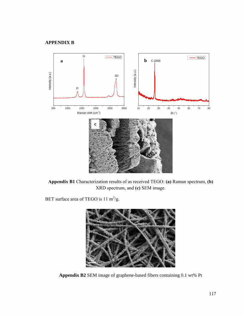
117
APPENDIX B
Appendix B1 Characterization results of as received TEGO: (a) Raman spectrum, (b)
XRD spectrum, and (c) SEM image.
BET surface area of TEGO is 11 m2/g.
Appendix B2 SEM image of graphene-based fibers containing 0.1 wt% Pt
500 1000 1500 2000 2500 3000
2D
G
Inte
nsity (
a.u
.)
Raman shift (cm-1)
TEGO
D
10 20 30 40 50 60 70 80
Inte
nsity (
a.u
.)
2
TEGOC (200)a b
c

118
Mark-Houwink-Sakurada equations:
C*=1/[ɳ] (1)
[ɳ]=KHMa (2)
Appendix B3 Mark-Houwink-Sakurada constants for PAN polymers at room
temperature.
Polymer
type Solvent a
KH (10-3
mL/g)
PAN DMF 0.780 17.7
where C* corresponds to the solution concentration where the hydrodynamic volumes
begin to overlap and Ce is the entanglement concentration which separates the semi-dilute
unentangled and semi-dilute entangled regimes. Ce value is approximately equal to 10C*
for neutral polymers in good solvent systems. By combining (1) and (2) the following
expression can be obtained:
C*= 5.65×10⁴Mw-0.780
Appendix B4 (a) and (b) TEM images of Pt decorated graphene-based fibers at different
regions.
a b

119
Appendix B5. Elemental mapping images of (a) oxygen and (b) carbon and (c) SEM
image of Pt decorated graphene-based foam, elemental mapping of (d) oxygen and (e)
carbon and (f) SEM image of Pt decorated graphene-based fiber, elemental mapping of
(g) oxygen and (h) carbon and (i) SEM image of Pt decorated graphene-based spheres.
Appendix B6 Elemental analysis of the Pt-graphene-based foam, fibers, and spheres
Pt decorated
graphene-
based
structures
C (wt%) O (wt%) Pt (wt%)
Foam 61 30 9
Fibers 70 25 5
Spheres 39 41 20

120
Appendix B7 (a) FTIR spectra of neat, reduced, and carbonized Pt decorated graphene-
based foam, and (b) Raman spectra of TEGO, Pt decorated carbon foam without
graphene and Pt decorated graphene-based carbon foam
Appendix B8 (a) FTIR spectra of neat, reduced, and carbonized Pt decorated graphene-
based spheres, and (b) Raman spectra of TEGO, Pt decorated carbon spheres without
graphene and Pt decorated graphene-based carbon spheres

121
Appendix B9 CV plots of Pt decorated neat TEGO sheets at different scan rates of 1, 5,
10, 50, and 100 mv/s.
The coulombic efficiency of the structures, ɳ, were determined using following
equation:
ɳ=tD/tC×100% (3)
where, tD and tC are discharging and charging times, respectively.
Appendix B10 Coulombic efficiency of Pt decorated graphene-based structures
Spheres Fibers Foam
Coulombic efficiency (%) at
a current density of 2 A/g
131 43 80
High coulombic efficiency of sphere structures was attributed to the rapid shrinkage
of 3D pores which causes the decomposition of electrodes as time passes. This result was
also confirmed by cyclic stability tests in which spheres shows a capacitance loss of 12%
after 1000 cycles of charging-discharging.
0,0 0,2 0,4 0,6 0,8
-0,5
0,0
0,5
1,0
1,5
2,0
2,5
Cu
rre
nt
de
nsity (
A/g
)
Potential (V)
1 mV/s
5 mV/s
10 mV/s
50 mV/s
100 mV/s

122
CURRICULUM VITAE
EDUCATION
2014-2018 Ph.D. in Materials Science and Engineering,
Sabanci University/Turkey (3.3/4)
2012-2014 M.S. in Materials Science and Engineering-Ceramics,
Istanbul Technical University/Turkey (3.2/4)
2006-2011 B.S. in Materials Science and Engineering-Ceramics,
Tabriz University/Iran (2.7/4)
WORK EXPERIENCE
2016-2018 Coordinator teaching assistant, Sabanci University, Introduction to
materials science
2014-2018 Research assistant, Sabanci University; SUNUM, SU-IMC
2014-2016 Teaching assistant, Sabanci University, Differential equations
2011-2014 Research assistant, Istanbul Technical University, Particulate materials
laboratory (PML)
Leila Haghighi Poudeh
Sabancı University,
Faculty of Engineerings and Natural Sciences,
Orhanlı 34956 Tuzla/İstanbul
Contact: [email protected]

123
RESEARCH EXPERIENCE
2014-2018 Ph.D. Dissertation, Design and manufacturing of dimensionally controlled
graphene-based hybrid structures by core-shell electrospinning for energy
storage systems
Prof. Dr. Mehmet Yıldız (advisor) and Assoc Prof. Dr. Burcu Saner Okan
(co-advisor), Sabanci University
2012-2014 M.S. Thesis, Production of WO3-MoO3-Cr2O3 composite powders via spray
drying and their sintering behavior
Assoc. Prof. Dr. Burak Özkal (advisor), Istanbul Technical University
2006-2011 B.S. Thesis, The effect of Chromite-Silica sands on the performance of ladle
filler sands for continuous casting
Prof. Dr. Mahdi Kakroudi (advisor), Tabriz University
PUBLICATIONS
1. Haghighi Poudeh, Leila and Cakmak Cebeci, Fevzi and Menceloglu, Yusuf Z and
Yildiz, Mehmet and Saner Okan, Burcu. "Free-Standing Hierarchical Hybrid Electrodes
Based on PANI Coated Mn3O4/Graphene Embedded Carbon Fibers for High
Performance Supercapacitors", 2018. (Submitted)
2. Çakal Saraç, Elçin and Haghighi Poudeh, Leila and Seyyed Monfared Zanjani, Jamal
and Pehlivan, Zeki Semih and Çakmak Cebeci, Fevzi and Aydin, İsmail, and Menceloglu,
Yusuf and Saner Okan, Burcu. "Investigation of synergetic effect of CVD grown carbon
fiber on graphene as a bicomponent reinforcement on the structural, thermal and
mechanical properties of polyamide 6.6 nanocomposites", 2018. (Submitted)
3. Seyyed Monfared Zanjani, Jamal and Haghighi Poudeh, Leila, and Girginer Ozunlu,
Burcu, and Yagcı, Yavuz Emre, and Menceloglu, Yusuf, and Saner Okan, Burcu “The
effect of graphene nanoplatelets on crystallization and mechanical reinforcement

124
behaviors of homo- and co-polymer polypropylene based nanocomposites”, 2018.
(Submitted)
4. Haghighi Poudeh, Leila and Cakiroglu, Dilek and Cakmak Cebeci, Fevzi and Yildiz,
Mehmet and Menceloglu, Yusuf Z and Saner Okan, Burcu. "Design of Pt supported 1D
and 3D multi-layer graphene-based structural composite electrodes with controlled
morphology by core-shell electrospinning/electrospraying". ACS Omega, 2018, Vol 3,
pages 6400-6410.
5. Ullah ,Mohib and Seyyed Monfared Zanjani, Jamal and Haghighi Poudeh, Leila and
Siddiq, Mohammad and Saner Okan, Burcu and Yıldız, Mehmet and Menceloglu, Yusuf
Z. "Manufacturing functionalized mono-crystalline diamond containing electrospun
fibers reinforced epoxy composites with improved mechanical characteristics". Diamond
and Related Materials, 2017, Vol.76, pages 90-96.
6. Haghighi Poudeh, Leila and Saner Okan, Burcu and Seyyed Monfared Zanjani, Jamal
and Yıldız, Mehmet and Menceloğlu, Yusuf Z. "Design and fabrication of hollow and
filled graphene-based polymeric spheres via core-shell electrospraying", RSC Advances,
2015, Vol.5, No.111, 91147-91157.
BOOK CHAPTERS
Haghighi Poudeh, Leila and Yildiz, Mehmet and Menceloglu, Yusuf Z and Saner Okan,
Burcu. "Three-dimensional Graphene Structures, Production Methods Properties, and
Applications". Graphene- Growth, Synthesis and Integration Methods, Handbook on the
Graphene Materials, WILEY-Scrivener Publisher, USA, 2018. (accepted-under
publication)

125
CONFERENCES
1. Haghighi Poudeh, Leila and Saner Okan, Burcu and Cebeci, Fevzi Cakmak and
Yildiz, Mehmet and Menceloglu, Yusuf.Z. “Dimension control of graphene-based
composite structures by core-shell electrospinning technology and development of new
emerging hybrid electrodes for the energy storage devices” 2. Ulusal Karbon
Konferansi, 2018, Istanbul, Turkey.
2. Haghighi Poudeh, Leila and Cakiroglu, Dilek and Cebeci, Fevzi Cakmak and
Yildiz, Mehmet and Menceloglu, Yusuf.Z and Saner Okan, Burcu. “Design and
Fabrication of 3D Graphene Based Composite Structures via Core-shell
Electrospinning Technique for Energy Storage Systems”. Graphene Week 2017,
Athens, Greece.
3. Haghighi Poudeh, Leila and Saner Okan, Burcu and Yıldız, Mehmet and
Menceloğlu, Yusuf Z. "Platinum decorated 3D/2D Graphene-based composites: New
emerging hybrid electrodes in the energy storage systems". 6. Fiziksel Kimya Kongresi,
2017, Zonguldak, Turkey. Oral presentation
4. Haghighi Poudeh, Leila and Menceloglu, Yesim and Saner Okan, Burcu and Yıldız,
Mehmet and Menceloğlu, Yusuf Z. "Production of Multi-walled Mn3O4-Graphene
Based Fibers via Tri-axial Electrospinning: New Generation of Hybrid Electrodes in
the Energy Storage Devices". GRAPHENE 3RD Emerging 2D Materials & Graphene
Conference 2016, Istanbul, Turkey. Poster presentation
5. Ateş Türkmen, Tülin and Haghighi Poudeh, Leila and Saner Okan, Burcu and
Altürk Parlak, Elif. "Effect of Graphene Oxide on Organic Photovoltaics".
GRAPHENE 3RD Emerging 2D Materials & Graphene Conference 2016, Istanbul,
Turkey. Poster presentation

126
6. Haghighi Poudeh, Leila and Saner Okan, Burcu and Seyyed Monfared Zanjani,
Jamal and Yıldız, Mehmet and Menceloğlu, Yusuf Z. "Design and Fabrication of Three
Dimensional Graphene Spheres with Controlled Hollowness via Core-shell
Electrospraying Technique". NanoTR12, 2016, Istanbul, Turkey. Oral presentation
7. Haghighi Poudeh, Leila and Saner Okan, Burcu and Seyyed Monfared Zanjani,
Jamal and Yıldız, Mehmet and Menceloğlu, Yusuf Z. "Integration of graphene sheets
into three dimensional spherical structures with controlled hollowness via core-shell
electrospraying technique". Graphene Week 2016, Warsaw, Poland. Poster
presentation
8. Haghighi Poudeh, Leila and Saner Okan, Burcu and Seyyed Monfared Zanjani,
Jamal and Yıldız, Mehmet and Menceloğlu, Yusuf Z. "Hollow and filled graphene-
based polymeric spheres via core-shell electrospinning", Graphene-Related
Technologies from Laboratory to Industry, 2015, Istanbul, Turkey. Oral presentation
9. Haghighi Poudeh, Leila and Saner Okan, Burcu and Yıldız, Mehmet and
Menceloğlu, Yusuf Z. "Synthesis and characterization of graphene-based polymeric
spheres via tri-axial electrospinning", 2nd Turkey-Japan Workshop on Polymeric
Composite Materials, 2015, Çeşme, Izmir, Turkey. Oral presentation
10. Saner Okan, Burcu and Seyyed Monfared Zanjani, Jamal and Haghighi Poudeh,
Leila and Yıldız, Mehmet and Menceloğlu, Yusuf Z. "Fabrication of graphene-
reinforced multi-walled electrospun fibers as reinforcing agent for epoxy composites",
COST Action MP1202 scientific workshop, 2014, Istanbul, Turkey. Oral presentation