design and manufacture of the optics - kicp workshops · adc grinding not undertaken by glass...
TRANSCRIPT

The optical upgrade of the Dark Energy Survey corrector
Dr David Brooks
Optical Science Laboratory
Department of Physics & Astronomy
University College London
KICP DESpec Workshop May 30-31-2012
Design and Manufacture of the Optics

Introduction
• Optical layout
• Optics costs
• Aspheric surface
• ADC
• Future R &D
2
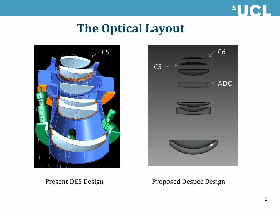
The Optical Layout
Present DES Design Proposed Despec Design
3
C6
C5
ADC
C5

New Components
• Original C5 to be replaced with new aspheric component.
• New additional C6
• New 4 element atmospheric dispersion corrector.
• Each new component will require a support cell
• ADC will require a rotary drive system.
• Metrology system for the fibre positioner.
4

Glass Manufacture’s
• Corning, HPFS C1 grade, C5 $33,000, C6 $30,000, 12 weeks.
• Heraeus, Superasil 312, C5 €15,000, C6 €35,000, 22 weeks.
• Schott, N-BK7 2,200, LLF1 £137,700, 1 year.
• Ohara, S-BSL7 €14,000, S-TIL1 & PBL1Y no bid
5
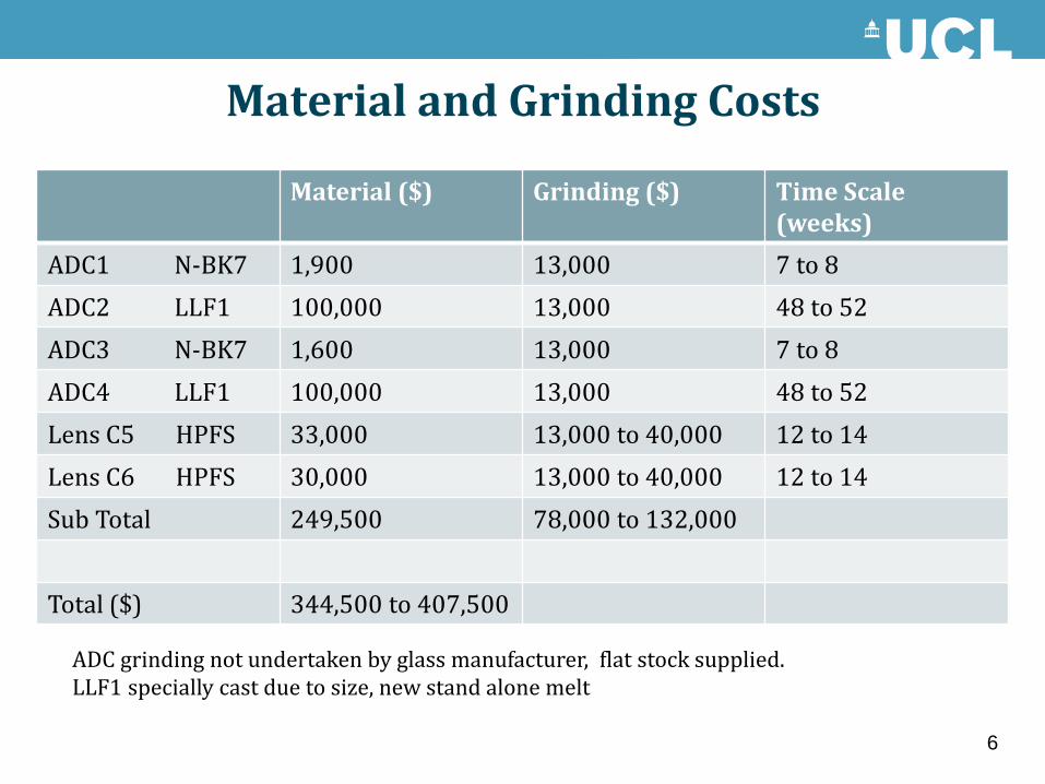
Material and Grinding Costs
6
Material ($) Grinding ($) Time Scale (weeks)
ADC1 N-BK7 1,900 13,000 7 to 8
ADC2 LLF1 100,000 13,000 48 to 52
ADC3 N-BK7 1,600 13,000 7 to 8
ADC4 LLF1 100,000 13,000 48 to 52
Lens C5 HPFS 33,000 13,000 to 40,000 12 to 14
Lens C6 HPFS 30,000 13,000 to 40,000 12 to 14
Sub Total 249,500 78,000 to 132,000
Total ($) 344,500 to 407,500
ADC grinding not undertaken by glass manufacturer, flat stock supplied. LLF1 specially cast due to size, new stand alone melt

Fine Grinding, Polishing & Coating Costs, ROM
• Time scale 16 to 18 months
• Testing, depends on accuracy required, test plate ,CGH, Ofner corrector etc.
• Coating, Anti reflection.
• DES C5 cost €55,000, Coating €35,000
7
Polishing (Euro) Coating (Euro)
ADC 1 50,000 to 60,000 15,000
ADC2 50,000 to 60,000 15,000
ADC3 50,000 to 60,000 15,000
ADC4 50,000 to 60,000 15,000
Lens C5 180,000 to 280,000 40,000
Lens C6 50,000 to 60,000 40,000
Sub Total 430,000 to 580,000 140,000
Total (Euro) 570,000 to 720,000
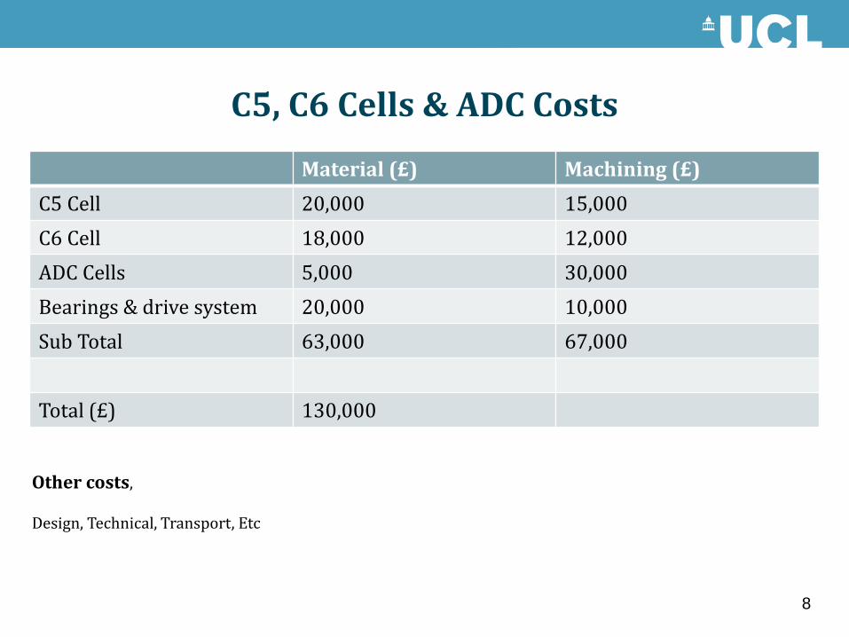
C5, C6 Cells & ADC Costs
Material (£) Machining (£)
C5 Cell 20,000 15,000
C6 Cell 18,000 12,000
ADC Cells 5,000 30,000
Bearings & drive system 20,000 10,000
Sub Total 63,000 67,000
Total (£) 130,000
8
Other costs, Design, Technical, Transport, Etc

Total Estimated Cost for mechanics and optics
Item Estimated cost ($)
Optical Materials 344,500 to 407,500
Grinding , Polishing & Coating 730,000 to 920,000
Cells and drive system 210,000
Total ($) 1,284,500 to 1,537,000
Metrology System for fibre placement 1,000,000
9
UCL Budget ($)
Research & Development 235,000
Total 235,000
Listing of surf ace sag
File : C:\Users \OSL\Documents\ Despec\Despec A DC2.ZMX
Title: Blanco P rime Focus Came ra, Despec Desi gn
Date : WED MAY 9 2012
Configuration 1 of 4
Units are Milli meters.
Semi-Diameter o f surface 21: 2.560000E+002.
Algorithm assum es +z goes from glass to air.
Method: Minimum Volume Removal
Best Fit Sphere Radius : 9.968512E+00 2
Best Fit Sphere Vertex Offset : 2.177028E-00 1
Maximum Depth t o Remove : 4.062672E-00 1
Volume To Remov e : 2.269531E+00 4 cubic Millime ters.
5
Y-coord Sag BFS Sag Deviation Remove
0.00E+00 0.00E+00 0.00E+00 0.00E+00 0.2177028 0 -0.2177
5.00E+00 1.27E-02 1.25E-02 1.84E-04 0.2175189 5 -0.21752
1.00E+01 5.09E-02 5.02E-02 7.37E-04 0.2169658 10 -0.21697
1.50E+01 1.15E-01 1.13E-01 1.66E-03 0.2160392 15 -0.21604
2.00E+01 2.04E-01 2.01E-01 2.97E-03 0.2147321 20 -0.21473
2.50E+01 3.18E-01 3.14E-01 4.67E-03 0.213035 25 -0.21304
3.00E+01 4.58E-01 4.52E-01 6.77E-03 0.210936 30 -0.21094
3.50E+01 6.24E-01 6.15E-01 9.28E-03 0.2084218 35 -0.20842
4.00E+01 8.15E-01 8.03E-01 1.22E-02 0.2054773 40 -0.20548
4.50E+01 1.03E+00 1.02E+00 1.56E-02 0.202087 45 -0.20209
5.00E+01 1.27E+00 1.25E+00 1.95E-02 0.198235 50 -0.19824
5.50E+01 1.54E+00 1.52E+00 2.38E-02 0.1939058 55 -0.19391
6.00E+01 1.84E+00 1.81E+00 2.86E-02 0.1890854 60 -0.18909
6.50E+01 2.16E+00 2.12E+00 3.39E-02 0.1837616 65 -0.18376
7.00E+01 2.50E+00 2.46E+00 3.98E-02 0.1779254 70 -0.17793
7.50E+01 2.87E+00 2.83E+00 4.61E-02 0.1715714 75 -0.17157
8.00E+01 3.27E+00 3.22E+00 5.30E-02 0.1646991 80 -0.1647
8.50E+01 3.69E+00 3.63E+00 6.04E-02 0.1573136 85 -0.15731
9.00E+01 4.14E+00 4.07E+00 6.83E-02 0.1494267 90 -0.14943
9.50E+01 4.61E+00 4.54E+00 7.66E-02 0.1410582 95 -0.14106
1.00E+02 5.11E+00 5.03E+00 8.55E-02 0.1322364 100 -0.13224
1.05E+02 5.64E+00 5.55E+00 9.47E-02 0.1229993 105 -0.123
1.10E+02 6.19E+00 6.09E+00 1.04E-01 0.1133958 110 -0.1134
1.15E+02 6.77E+00 6.66E+00 1.14E-01 0.1034863 115 -0.10349
1.20E+02 7.37E+00 7.25E+00 1.24E-01 0.09334376 120 -0.09334
1.25E+02 8.00E+00 7.87E+00 1.35E-01 0.08305468 125 -0.08305
1.30E+02 8.66E+00 8.51E+00 1.45E-01 0.07271962 130 -0.07272
1.35E+02 9.34E+00 9.18E+00 1.55E-01 0.06245404 135 -0.06245
1.40E+02 1.00E+01 9.88E+00 1.65E-01 0.05238887 140 -0.05239
1.45E+02 1.08E+01 1.06E+01 1.75E-01 0.04267099 145 -0.04267
1.50E+02 1.15E+01 1.14E+01 1.84E-01 0.0334636 150 -0.03346
1.55E+02 1.23E+01 1.21E+01 1.93E-01 0.02494638 155 -0.02495
1.60E+02 1.31E+01 1.29E+01 2.00E-01 0.01731558 160 -0.01732
1.65E+02 1.40E+01 1.38E+01 2.07E-01 0.01078387 165 -0.01078
1.70E+02 1.48E+01 1.46E+01 2.12E-01 0.005579991 170 -0.00558
1.75E+02 1.57E+01 1.55E+01 2.16E-01 0.001948228 175 -0.00195
1.80E+02 1.66E+01 1.64E+01 2.18E-01 0.000147606 180 -0.00015
1.85E+02 1.75E+01 1.73E+01 2.17E-01 0.000450852 185 -0.00045
1.90E+02 1.85E+01 1.83E+01 2.15E-01 0.003143076 190 -0.00314
1.95E+02 1.95E+01 1.93E+01 2.09E-01 0.008520149 195 -0.00852
2.00E+02 2.05E+01 2.03E+01 2.01E-01 0.01688677 200 -0.01689
2.05E+02 2.15E+01 2.13E+01 1.89E-01 0.02855418 205 -0.02855
2.10E+02 2.25E+01 2.24E+01 1.74E-01 0.04383752 210 -0.04384
2.15E+02 2.36E+01 2.35E+01 1.55E-01 0.0630528 215 -0.06305
2.20E+02 2.47E+01 2.46E+01 1.31E-01 0.08651345 220 -0.08651
2.25E+02 2.58E+01 2.57E+01 1.03E-01 0.1145264 225 -0.11453
2.30E+02 2.70E+01 2.69E+01 7.03E-02 0.147388 230 -0.14739
2.35E+02 2.81E+01 2.81E+01 3.23E-02 0.1853785 235 -0.18538
2.40E+02 2.93E+01 2.93E+01 -1.11E-02 0.2287576 240 -0.22876
2.45E+02 3.05E+01 3.06E+01 -6.01E-02 0.2777579 245 -0.27776
2.50E+02 3.17E+01 3.19E+01 -1.15E-01 0.3325787 250 -0.33258
2.55E+02 3.30E+01 3.32E+01 -1.76E-01 0.3933789 255 -0.39338
2.56E+02 3.32E+01 3.34E+01 -1.89E-01 0.4062672 256 -0.40627
1002.315 BFS Radius of curvature at vertex 982.454
Conic constant 0
4th Term 1.88E-10
6th Term -7.82E-15
8th Term 3.78E-20
0.001017859 1/vr Step size 10
0 conic
BFS
Rad Z Asphere Z asp + terms ROC Z Sphere Diff Sp/Asp Dif +terms
0 0 0 1004635.36 1002.315 0 0 0
10 0.050894286 0.050896163 1004535.36 1002.265 0.04988576 -0.00100853 0.001010404
15 0.114515852 0.114525302 1004410.36 1002.203 0.11224645 -0.0022694 0.002278853
25 0.318132558 0.318204254 1004010.36 1002.003 0.31182674 -0.00630582 0.006377515
35 0.623636793 0.62390524 1003410.36 1001.704 0.61127173 -0.01236506 0.012633507
45 1.031123705 1.031832003 1002610.36 1001.304 1.01067102 -0.02045268 0.021160979
55 1.54072039 1.542231124 1001610.36 1000.805 1.51014428 -0.03057611 0.03208684
65 2.152586089 2.155371435 1000410.36 1000.205 2.10984143 -0.04274466 0.045530002
75 2.866912439 2.871519438 999010.359 999.5051 2.80994287 -0.05696957 0.061576566
85 3.683923774 3.690911482 997410.359 998.7043 3.61065975 -0.07326402 0.080251727
95 4.603877478 4.613723619 995610.359 997.8028 4.51223431 -0.09164317 0.101489312
105 5.627064399 5.640040203 993610.359 996.8001 5.5149402 -0.1121242 0.125100007
115 6.753809308 6.769822453 991410.359 995.6959 6.61908295 -0.13472636 0.1507395
125 7.984471428 8.002878359 989010.359 994.49 7.82500044 -0.15947099 0.177877919
135 9.31944501 9.338835449 986410.359 993.1819 9.13306338 -0.18638163 0.205772067
145 10.75915998 10.77711809 983610.359 991.7713 10.5436759 -0.21548404 0.233442153
150 11.51843977 11.53439189 982135.359 991.0274 11.2875739 -0.23086584 0.246817961
160 13.11615275 13.12460103 979035.359 989.4622 12.8528435 -0.26330929 0.271757571
170 14.81984283 14.81472187 975735.359 987.7932 14.5218237 -0.29801917 0.292898212
180 16.63007085 16.60339939 972235.359 986.02 16.2950412 -0.33502969 0.308358228
190 18.54743704 18.48908219 968535.359 984.1419 18.1730594 -0.37437763 0.31602278
200 20.57258209 20.47006162 964635.359 982.1585 20.1564796 -0.41610251 0.313582034
210 22.70618827 22.54453005 960535.359 980.0691 22.2459416 -0.46024667 0.298588444
220 24.94898063 24.71066117 956235.359 977.8729 24.4421252 -0.50685541 0.268535948
230 27.30172831 26.96671525 951735.359 975.5692 26.7457512 -0.55597712 0.22096406
240 29.76524594 29.31117248 947035.359 973.1574 29.1575825 -0.60766343 0.153589977
250 32.34039515 31.74289775 942135.359 970.6366 31.6784258 -0.66196938 0.064471973
256 33.93944444 33.24356125 939099.359 969.0714 33.2436098 -0.6958346 -4.85909E-05
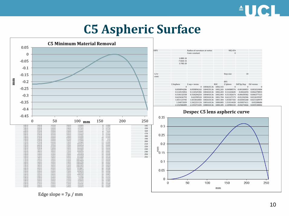
C5 Aspheric Surface
-0.45
-0.4
-0.35
-0.3
-0.25
-0.2
-0.15
-0.1
-0.05
0
0.05
0 50 100 150 200 250
mm
mm
C5 Minimum Material Removal
Edge slope = 7µ / mm
10

Alignment Tolerance's
• The alignment tolerances on Decam were tight, I know because I worked to them.
• Adding another asphere is possibly achievable, however the placement tolerance will have to be looked at in some detail.
• Numbers required for the alignment and the focal plain.
11

Considerations on Constructing the ADC All the new optics are thin and the optical manufactures do not like that, some have suggested a
50% thickening of all elements.
The main consideration is how to support the optics during manufacture and during assembly. Having high aspect ratio components make the manufacture, that is fine grinding, polishing and testing very difficult.
Not just the distortion in mounting and handling in manufacture but also ensuring that the components do not move during gluing.
What AR coatings are require, any Mil specification, Mg/F2 , Si/O2 , Solgel.
N-BK7 optical glass has a transmission curve rising at precisely the wavelength that most UV curing cements require for cure. Bonded N-BK7 elements have lower resistance to heat, humidity, and mechanical stress than fused silica when using the same light source, length of exposure, and distance from substrates. Possible distortion problems.
12

Optically coupling the ADC components ADC joint,
This is critical as any distortion caused by the gluing will show as a wave front error.
The joints can be air gap, cemented, oiled.
Each has its merits and should be investigated to establish the best possible for this application.
Types of cement
• Dow Corning RTV type two part elastomer, Sylgard 184.
• Norland cements, noa 60, General purpose adhesive for bonding doublets, prisms or mounting components. noa 61 Preferred adhesive for military optics. Meets MIL-A-3920. Used for optics exposed to temperature extremes. Low shrinkage. UV curing refractive index 1.56
• Lensbond cements UV curing (uv-69, uv-71, uv-74) refractive index 1.55, transparent from 0.4 to 2.5 microns.
• Milibond , Type UV-69 A one component, ultraviolet curing cement. Cure is achieved by using an ordinary sun lamp. Type J-91 A general purpose, one component, water white, 100% solids ultraviolet curing optical cement. This cement meets the requirements of MIL-A-3920.
• Dymax optical adhesives Ultra Light-Weld® OP-4-20632 is a clear UV/Visible light-curable fibre optical assembly adhesive designed for rapid, durable bonding of fibre optic couplings and prisms.
• Cargille oils, They can produce any refractive index and viscosity required.
13

ADC Coupling Problems
• Adhesive failure occurs when the cement separates from the glass surface. It is seen as a shiny area in reflected light. It can be any shape and can be identified by the presence of Newton rings, or a colour fringe.
• Cohesive failure occurs when the cement pulls away from itself. This can be identified by the fern-like voids, called feathering, appearing along the edge of the lens or sometimes in the interior.
• Haze, Fog or Discoloration of Bond Layer, Generally caused by some kind of contamination, reaction to mixing vessel, humidity, or solvent.
14

Optically decoupling the ADC components
UV Curing Cement removal
Several methods can be used to remove the adhesives. Lens bond decementing agent and Milsolve to name two. The easiest and simplest method is to immerse the lens in a solvent such as methylene chloride. Usually small lenses can be separated easily before it is cured by an overnight soak. The glass can be heated in oil or other medium until the bonds break and the glass separates, this would be done at around 200°C.
However these are high aspect ratio elements that will be extremely difficult to separate if there is a problem, with a high risk of total failure.
RTV
This can be removed with acetone, however the diameter of the ADC is large and the gap small, which will make this a long process that could effect the coating.
Oil
Ease of separation and cleaning.
15

Pros and Cons of Coupling Agent
Advantages and Limitations of UV Glue
There are many advantages to using UV curable optical cements. They are use in a wide variety of opto-mechanical assemblies. It allows alignment and checking of the assemblies before bonding and has a quick cure time to hold the alignment in place. It works in a wide variety of compounds to produce bonds that function in a large range of temperatures from -60o to 180oC. UV systems curve substrates at low temperatures . Difficult to undo.
Advantages and Limitations of Elastomer Adhesive
Sylgard 184 requires a primer, Dow Corning 92-023 or 1200 os, (I did not notice a primer used when bonding the ODI ADC). It allows alignment and checking of the assemblies before bonding has cured and has a very slow cure time. RTV needs to be filtered to remove particulates. Difficult to undo
Advantages and Limitations of Oils
They can go waxy and opaque at low temperatures. Possibility of leaks. Easy removed and replenished. Requires a reservoir of oil to compensate for temperature and topping up from time to time. Also will require lens spacers to maintain correct gap.
16

Oiled ADC designs
Section through possible
Despec ADC design
17

Glued ADC Designs
MMT wide field corrector
18
WIYN 3.5m One Degree Imager ADC
ADC on the Wide-Field Corrector for the Mayall Telescope

ADC Mechanics & Glass handling
• Rotary position sensing mechanism
• Geared drive system
• Precision bearings
• Lens cells Nickel iron for the C5 & C6, Stainless steel for the ADC.
19
Handling of the glass
The glass for the ADC is thin and will distort under its own weight due to
gravity. Thus care must be taken to ensure that the mounting sub-straight is
supported correctly without any distortions. Any edge supporting ring will
probably distort the glass. Fixture for holding the glass and vacuum lifting
structure will be necessary to hold the glass during the gluing and curing
procedure.

Future R & D • Optimise optical design for ease of manufacture.
• Optics need to be thicker, by a high percentage
• Work with polishing companies on testing of optics.
• Look at other optical glasses (N-BK7, CTE to high)
• Investigate the best possible coupling material.
• Develop coupling methods.
• Monitor any optical distortion due to glue.
• Design handling equipment.
• Determine the optical alignment procedure.
• Fibre positioning metrology system.
20

End, Thank You
Dr David Brooks
Optical Science Laboratory
Department of Physics & Astronomy
University College London
21

Gravity deflection on 29mm plate
Edge constrained
Corner constrained
22
Extra slides

Bonding the ODI Atmospheric Dispersion Compensators with Sylgard 184
Gary A. Poczulp
23
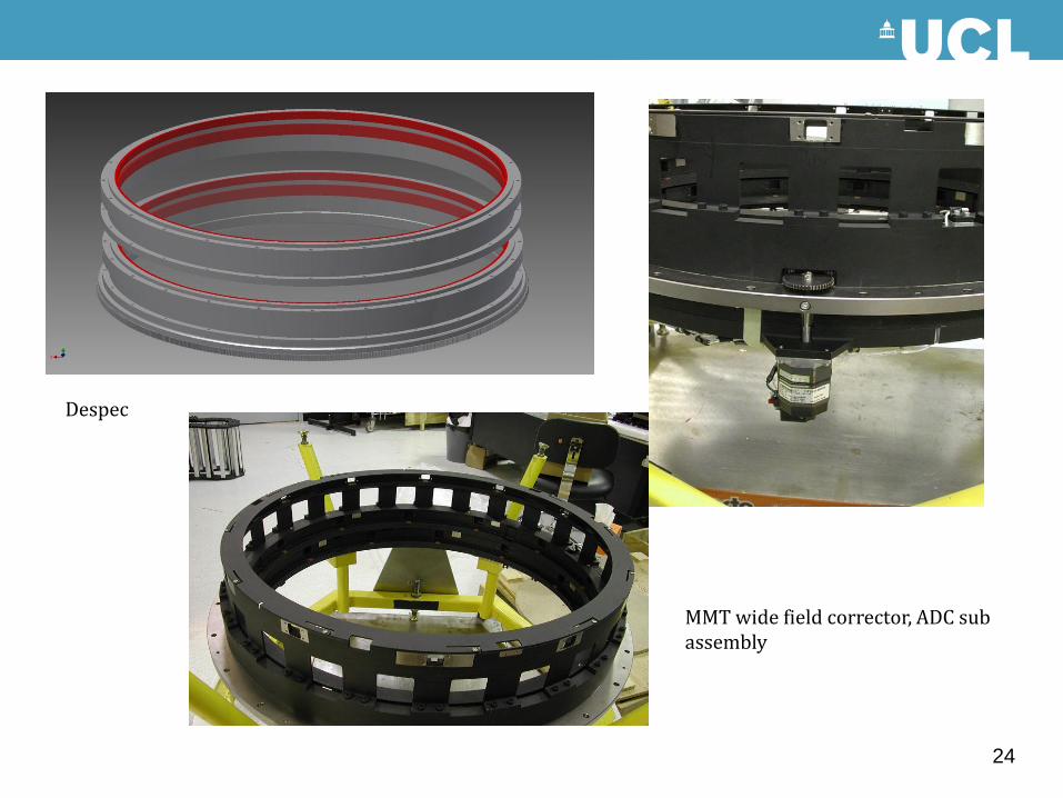
MMT wide field corrector, ADC sub assembly
Despec
24

Gemini ADC & image stabilizer
Despec ADC glass
The Keck -1 Cassegrain ADC
25
Large size slewing ring bearing