design and installation guidelines for advance warning ... · design and installation guidelines...
TRANSCRIPT
Technical Report Documentation Page 1. Report No. FHWA/TX-04/0-4260-2
2. Government Accession No.
3. Recipient's Catalog No. 5. Report Date September 2003 Resubmitted: December 2003
4. Title and Subtitle DESIGN AND INSTALLATION GUIDELINES FOR ADVANCE WARNING SYSTEMS FOR END-OF-GREEN PHASE AT HIGH SPEED TRAFFIC SIGNALS
6. Performing Organization Code
7. Author(s) Carroll J. Messer, Srinivasa R. Sunkari, and Hassan A. Charara
8. Performing Organization Report No. Report 0-4260-2 10. Work Unit No. (TRAIS)
9. Performing Organization Name and Address Texas Transportation Institute The Texas A&M University System College Station, Texas 77843-3135
11. Contract or Grant No. Project No. 0-4260 13. Type of Report and Period Covered Research: September 2001-August 2003
12. Sponsoring Agency Name and Address Texas Department of Transportation Research and Technology Implementation Office P. O. Box 5080 Austin, Texas 78763-5080
14. Sponsoring Agency Code
15. Supplementary Notes Research performed in cooperation with the Texas Department of Transportation and the U.S. Department of Transportation, Federal Highway Administration. Research Project Title: Advance Warning for End-of-Green Phase at High Speed Traffic Signals 16. Abstract This report describes the research conducted within a two-year study that developed an effective advance warning for end-of-green phase at high-speed traffic signals in Texas. High-speed signals are defined as having approach speeds of 45 mph or more. The Advance Warning for End-of-Green Signal (AWEGS) was developed in this research by the Texas Transportation Institute for the Texas Department of Transportation (TxDOT). Two AWEGS were designed and the field tests showed a 40-45 percent reduction in red-light running can be expected with well designed, constructed, and maintained systems. This report provides a manual that traffic engineers can use to design and install an AWEGS in the field to improve the safety experience with problematic traffic-actuated signalized intersections. Advance detector design and layout guidelines are provided together with sign design and deployment guidance. A set of uniformly spaced dilemma zone detectors is presumed to be in place on each high-speed approach at the existing traffic actuated signalized intersection to which the AWEGS is envisioned to be added as a safety treatment. A Microsoft™ Excel-based software, named AWEGS Designer, which can be used to design and layout an AWEGS is available online at http://tti.tamu.edu/documents/0-4260-2-awegs.xls. 17. Key Words Advance Warning Flashers, AWEGS, Advance Traffic Control Signs, W3-4 Signs, Advance Traffic Warning Devices, Traffic Actuated Control
18. Distribution Statement No restrictions. This document is available to the public through NTIS: National Technical Information Service 5285 Port Royal Road Springfield, Virginia 22161
19. Security Classif.(of this report) Unclassified
20. Security Classif.(of this page) Unclassified
21. No. of Pages 40
22. Price
Form DOT F 1700.7 (8-72) Reproduction of completed page authorized

DESIGN AND INSTALLATION GUIDELINES FOR ADVANCE WARNING SYSTEMS FOR END-OF-GREEN PHASE AT HIGH
SPEED TRAFFIC SIGNALS
by
Carroll J. Messer, P.E. Research Engineer
Texas Transportation Institute
Srinivasa R. Sunkari, P.E. Associate Research Engineer Texas Transportation Institute
and
Hassan A. Charara
Associate Research Scientist Texas Transportation Institute
Report 0-4260-2 Project Number 0-4260
Research Project Title: Advance Warning for End-of Green Phase at High Speed Traffic Signals
Sponsored by the Texas Department of Transportation
In Cooperation with the U.S. Department of Transportation Federal Highway Administration
September 2003 Resubmitted: December 2003
TEXAS TRANSPORTATION INSTITUTE The Texas A&M University System College Station, Texas 77843-3135

v
DISCLAIMER
The contents of this report reflect the views of the authors, who are solely responsible for the facts and accuracy of the data, the opinions, and the conclusions presented herein. The contents do not necessarily reflect the official views or policies of the Federal Highway Administration (FHWA) or the Texas Department of Transportation (TxDOT). This report does not constitute a standard or regulation, and its contents are not intended for construction, bidding, or permit purposes. The use and names of specific products or manufacturers listed herein does not imply endorsement of these products or manufacturers. The United States Government and the State of Texas do not endorse products or manufacturers. Trade or manufacturers’ names may appear herein solely because they are considered essential to the object of this report. The engineer in charge of the project was Carroll J. Messer, P.E., (Texas # 31409).
vi
ACKNOWLEDGMENTS
This research was conducted during a two-year study under a cooperative research program between the Texas Transportation Institute (TTI), TxDOT, and Federal Highway Administration. Michael Jedlicka of TxDOT in the Bryan District was the project director (PD). Other TxDOT members of the project monitoring committee included Don Baker, Dale Barron, Glenn Campbell, Ted Copeland, Carlos Ibarra, Roy Parikh, Ismael Soto, and Doug Vanover. Robert R. Kovar and Tom Beeman of the Design Division were the program coordinators. Grant Schultz, Roelof Engelbrecht, Ricky Parker, and Kwaku Obeng-Boampong of TTI also contributed to the materials used in this report. Grant Schultz prepared an initial draft of the literature review. Ricky Parker made major contributions to the design of the backup flasher system together with field wiring and other related electrician services provided by TTI. Hassan Charara provided the software interface design for laboratory testing and program coding of the AWEGS run on the field computers. Kwaku Obeng-Boampong conducted all of the video data reduction and analysis for red-light-running of the AWEGS operations conducted at two field sites in Texas.
vii
TABLE OF CONTENTS
Page LIST OF FIGURES ....................................................................................................... viii LIST OF TABLES ........................................................................................................... ix CHAPTER 1. INTRODUCTION.................................................................................. 1
BACKGROUND ............................................................................................................ 1 AWEGS .......................................................................................................................... 1 NADER’S DETECTOR GUIDE.................................................................................... 3 NEED FOR AWEGS...................................................................................................... 4
Minnesota Application Guide ..................................................................................... 4 Operational Objective ................................................................................................. 5
CHAPTER 2. DATA FOR DESIGN............................................................................. 7
SPOT-SPEED DATA ..................................................................................................... 7 EXISTING DILEMMA ZONE DETECTION LAYOUT ............................................. 9 APPROACH ROADWAY GEOMETRY .................................................................... 10 APPROACH ROADWAY SUMMARY...................................................................... 11
CHAPTER 3. DESIGN OF AWEGS .......................................................................... 13
DESIGN PROBLEM.................................................................................................... 13 SIGN DESIGN.............................................................................................................. 13
Features ..................................................................................................................... 15 Location .................................................................................................................... 15 Electrical ................................................................................................................... 16
ADVANCE WARNING DETECTORS....................................................................... 17 Location .................................................................................................................... 17 Spreadsheet ............................................................................................................... 20 Loop Layout and Wiring........................................................................................... 21
SYSTEM....................................................................................................................... 22 Cabinet ...................................................................................................................... 22 Computer................................................................................................................... 22 Software Flasher System........................................................................................... 23 Backup/Watchdog Flasher ........................................................................................ 23 Timer Relay for Phase Holds.................................................................................... 24 Resistor Input Interface Circuit for NIDAQ 6527 .................................................... 24
REFERENCES................................................................................................................ 25 APPENDIX A EXAMPLE SPREADSHEET OF AWEGS DESIGNER ................ 27

viii
LIST OF FIGURES Figure Page
1. Examples of AWEGS Advance Warning Signs in Waco and Brenham. ................2
2. Example of Cantilevered Electronic Matrix Advance Warning Sign Located in Marshall .................................................................................................3
3. Example of Spot-Speed Data and Resulting High-Speed Traffic Not Covered by Typical (85th percentile) Dilemma Zone Detection Layouts................8
4. Probability of First Detector Gap-out by Design Speed for Nader’s Guide. ...........9 5. Summary of Existing Conditions of High-Speed Approach and Proposed Layout of AWEGS Detectors and Signs................................................................11
6. Design Features and Flow of Advance Warning for End-of-Green System (AWEGS)...............................................................................................................14
7. Distance to the Stopline for ADA, BDA and CDA1 Detectors (from Nader’s Guide) as Related to Design (85th percentile) Speed for Level Grades ..........................................................................................................19
8. Example of Sheet 1 from AWEGS Designer.........................................................20
9. Design Layout of AWEGS Speed-Trap Advance Detectors .................................21

ix
LIST OF TABLES Table Page
1. Nader’s Guide on Detector Installation for High-Speed Approaches. (3)...............4
2. Locations of AWEGS Advance Speed-Trap Detectors and W3-4 Sign for Level Grade Using Nader’s Guide for Dilemma Zone Detection....................19


1
CHAPTER 1. INTRODUCTION
BACKGROUND
Research sponsored by the Texas Department of Transportation has developed an Advanced Warning for End-of-Green System (AWEGS) for applications to high-speed signalized intersections in isolated (non-coordinated) locations. This report contains the guidelines developed by the research team at Texas Transportation Institute to assist traffic engineers in the design and installation of AWEGS. This manual emphasizes deployment along rural Texas highways having traffic-actuated signals, although AWEGS could be readily installed anywhere similar conditions exist. A companion report provides a manual for traffic signal technicians to use as a guide for installation and maintenance of AWEGS (1). The research project’s final report provides the complete research, theory of operation, and field evaluation of AWEGS (2).
AWEGS
What does AWEGS look like in the field? Advance warning to approaching motorists of the forthcoming end-of-green is provided by a warning sign and activation of its warning beacons by the local AWEGS computer control logic. Types of AWEGS advance warning signs that may be used include: (1) a single W3-4 sign (advance traffic control sign) shown in Figure 1a for two-lane, two-way, undivided roadways; (2) dual W3-4 signs for divided highways as shown in Figure 1b, and (3) possibly an overhead mounted sign where conditions are deemed warranted. Overhead options include the W3-4 sign with flashing beacons mounted on span-wires or on a rigid steel mast arm. Where complex roadway and environmental conditions exist and more communication power and flexibility are desired, an electronic matrix warning sign mounted on a cantilevered sign support as shown in Figure 2 could be used. No overhead signs were field tested in this research, but they have been widely deployed in Canada (2). What does an AWEGS do that current advance traffic control signs (i.e., W3-3) don’t already do to warn motorists about a signalized intersection ahead? Traffic engineers sometimes install passive W3-3 signs when visibility or traffic conditions warrant, and they may also add two flashing warning beacons to provide additional attention-getting value to the sign message. These beacons flash continuously regardless of the state of the downstream traffic signal. However, this constantly “barking” operation may tend to lose its effectiveness with widespread usage over time. Moreover, flashers are distracting when the signal ahead is green and may provide little useful or timely information that the approaching motorist can and will use. AWEGS does not flash unless it thinks the downstream thru phase, now green, is about to end. When it flashes, it means business!

2
a. Pole-mounted AWEGS Advance Traffic Control Sign (W3-4) near Waco.
b. Two Pole-mounted AWEGS Advance Traffic Control Signs (W3-4) in Brenham.
Figure 1. Examples of AWEGS Advance Warning Signs in Waco and Brenham.
3
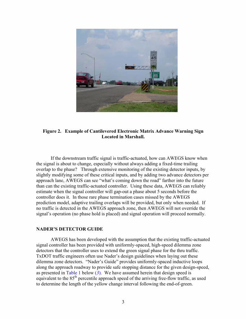
Figure 2. Example of Cantilevered Electronic Matrix Advance Warning Sign Located in Marshall.
If the downstream traffic signal is traffic-actuated, how can AWEGS know when the signal is about to change, especially without always adding a fixed-time trailing overlap to the phase? Through extensive monitoring of the existing detector inputs, by slightly modifying some of these critical inputs, and by adding two advance detectors per approach lane, AWEGS can see “what’s coming down the road” farther into the future than can the existing traffic-actuated controller. Using these data, AWEGS can reliably estimate when the signal controller will gap-out a phase about 5 seconds before the controller does it. In those rare phase termination cases missed by the AWEGS prediction model, adaptive trailing overlaps will be provided, but only when needed. If no traffic is detected in the AWEGS approach zone, then AWEGS will not override the signal’s operation (no phase hold is placed) and signal operation will proceed normally.
NADER’S DETECTOR GUIDE
AWEGS has been developed with the assumption that the existing traffic-actuated signal controller has been provided with uniformly-spaced, high-speed dilemma zone detectors that the controller uses to extend the green signal phase for the thru traffic. TxDOT traffic engineers often use Nader’s design guidelines when laying out these dilemma zone detectors. “Nader’s Guide” provides uniformly-spaced inductive loops along the approach roadway to provide safe stopping distance for the given design-speed, as presented in Table 1 below (3). We have assumed herein that design speed is equivalent to the 85th percentile approach speed of the arriving free-flow traffic, as used to determine the length of the yellow change interval following the end-of-green.

4
Table 1. Nader’s Guide on Detector Installation for High-Speed Approaches. (3)
Distance from Head of Detector to Stopline at Intersection, feet
Approach Speed, mph CDA 1 CDA 2 CDA 3
Stopline Area
Detector a
Passage Gap, Sec
TTI Rec. Min. Passage
Gap, sec b
45 330 210 --- 6′ x 40′ 2.0 2.8 50 350 220 --- 6′ x 40′ 2.0 2.8 55 415 320 225 6′ x 40′ 1.2 1.6 60 475 375 275 6′ x 40′ 1.4 1.5 65 540 430 320 6′ x 40′ 1.2 1.6 70 600 475 350 6′ x 40′ 1.2 1.7
a Presence on red; then delayed (off) call on green following first (queue) gap-out. bMinimum recommended passage gap in Nader’s Guide (3) detector layout by TTI (2). Table 1 also provides the passage gaps that Nader’s Guide recommends for the respective signal phases. However, research in this project has shown that passage gaps longer than those given in Table 1 have been and should be used in the field in most cases to minimize the number of slower vehicles unexpectedly gapping out between the detectors. The right-hand column of Table 1 provides recommended minimum passage gaps for these design conditions based on this research (2).
NEED FOR AWEGS
As AWEGS is a very new system, Texas has no formal warranting procedure for its installation. Some installation authorization is provided in Section C of the 2000 Manual on Uniform Traffic Control Devices (MUTCD, 4) covering advance traffic control sign applications, particularly the new W3-4 BE PREPARED TO STOP sign (with When Flashing plaque). Many Advance Warning Flashers (AWF) are installed around the country, but it is unclear whether any of these systems have the operational efficiency provided by the prediction features of AWEGS. In any case, the best application guidance that can be gleaned from the current literature and research is summarized in a recent Minnesota Dept. of Transportation (MnDOT) technical memorandum on the subject dated August 2000 (5). MnDOT has conducted several research projects on applications of advance warning flashers during the past decade, and their implementation guidelines reflect this expertise.
Minnesota Application Guide
The Minnesota DOT guidelines (5) state that “AWF should only be installed in response to a specifically correctable problem, not in anticipation of a future problem. Generally, AWF implementation is appropriate only at high-speed locations. Before an AWF is installed, other remedial actions should be considered.”

5
The MnDOT guide continues with a taxonomy of potential problem categories for which application criteria and comment were provided: “The following guidelines for Advance Warning Flashers which include guidelines from American Association of State Highway Transportation Officials (AASHTO) and Institute of Transportation Engineers (ITE) generally apply only where the posted speed is 55 mph or higher by category and [criteria]: 1. isolated or unexpected signalized intersection [>10 miles to next signal];
2. limited sight distance of 2 signals [<AASHTO stop dist, truck decel - 20 percent];
3. dilemma zone [ITE stopping distance, truck decel. reduced 20 percent]; 4. accidents [and problem type 2 or 3 above exists]; 5. heavy truck volume [ grade >3 percent with > 15 percent trucks]; and 6. engineering judgment.” This MnDOT advance warning flasher guide (5) is generally consistent with other prior published research and traffic engineering practice on advance warning flashers (2).
Operational Objective
The basic operational goal of AWEGS is to get targeted motorists approaching a signalized (traffic actuated) intersection at high speed to immediately slow down to a speed from which they can safely stop when the signal turns yellow and then red shortly thereafter. Yellow lights are not generally timed for these high speeds (i.e., usually illegal speeds above the speed limit). A flashing warning (e.g., beacon) is activated to warn approaching motorists when AWEGS detects that the traffic signal phase is about to end, usually in about 5 seconds. An additional function provided by AWEGS is to minimize dilemma zone exposure to trucks and high-speed cars when the signal is operating in the “green rest” state. Thus, it is essential to know the distribution of approach speeds expected to be served by AWEGS.

7
CHAPTER 2. DATA FOR DESIGN AWEGS should be designed with the best traffic and roadway data that can be obtained. In addition, an accurate inventory of the existing traffic detector layouts (e.g., from Nader’s Guide) must be provided. Even the type of existing signal controller, cabinet features, and signal timings must be determined. As current AWEGS design requires the installation of a hardened industrial-grade computer, space availability in the cabinet and the quality of cooling system are important factors that should be determined. Construction and installation of inductive loop detectors to the designated spacing and sizes are also paramount.
SPOT-SPEED DATA
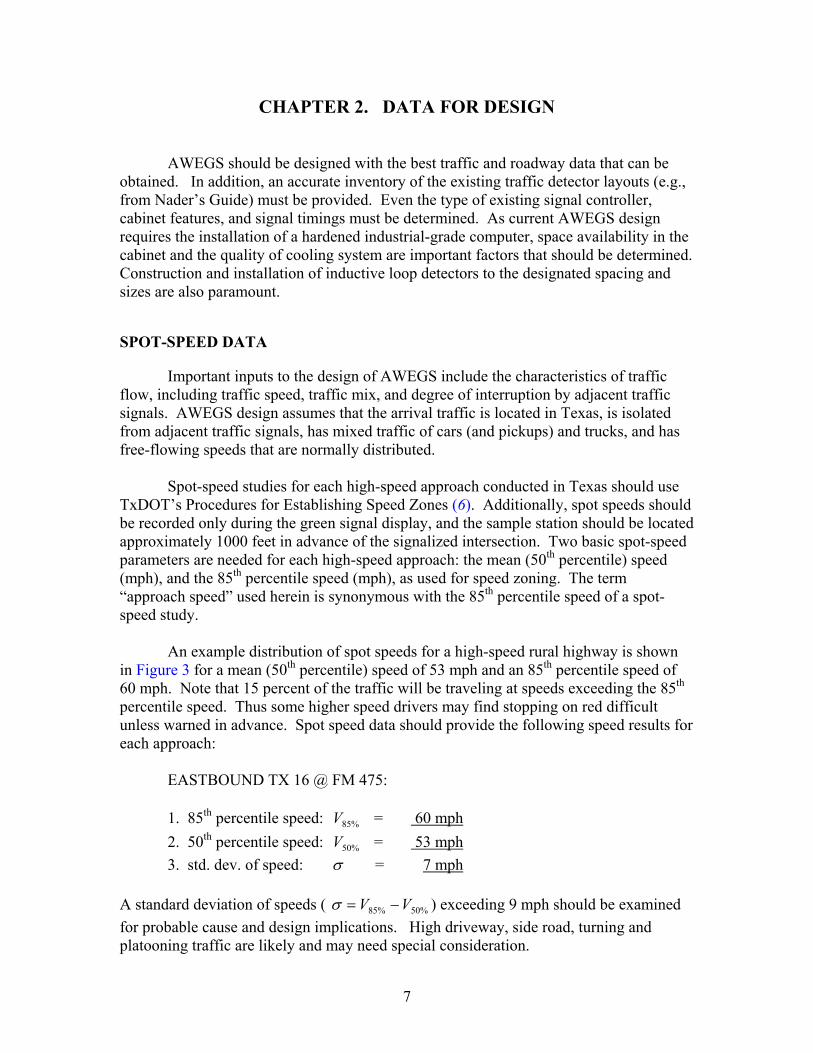
Important inputs to the design of AWEGS include the characteristics of traffic flow, including traffic speed, traffic mix, and degree of interruption by adjacent traffic signals. AWEGS design assumes that the arrival traffic is located in Texas, is isolated from adjacent traffic signals, has mixed traffic of cars (and pickups) and trucks, and has free-flowing speeds that are normally distributed. Spot-speed studies for each high-speed approach conducted in Texas should use TxDOT’s Procedures for Establishing Speed Zones (6). Additionally, spot speeds should be recorded only during the green signal display, and the sample station should be located approximately 1000 feet in advance of the signalized intersection. Two basic spot-speed parameters are needed for each high-speed approach: the mean (50th percentile) speed (mph), and the 85th percentile speed (mph), as used for speed zoning. The term “approach speed” used herein is synonymous with the 85th percentile speed of a spot-speed study. An example distribution of spot speeds for a high-speed rural highway is shown in Figure 3 for a mean (50th percentile) speed of 53 mph and an 85th percentile speed of 60 mph. Note that 15 percent of the traffic will be traveling at speeds exceeding the 85th percentile speed. Thus some higher speed drivers may find stopping on red difficult unless warned in advance. Spot speed data should provide the following speed results for each approach: EASTBOUND TX 16 @ FM 475: 1. 85th percentile speed: %85V = 60 mph 2. 50th percentile speed: %50V = 53 mph 3. std. dev. of speed: σ = 7 mph A standard deviation of speeds ( %50%85 VV −=σ ) exceeding 9 mph should be examined for probable cause and design implications. High driveway, side road, turning and platooning traffic are likely and may need special consideration.
8
Spot-Speed Density
0
0.01
0.02
0.03
0.04
0.05
0.06
30 40 50 60 70 80
Approach Speed, mph
Dis
tribu
tion
Den
sity
a. Distribution Density of Approach Spot Speeds.
Cumulative Speed Distribution
0
0.2
0.4
0.6
0.8
1
30 40 50 60 70 80
Approach Speed, mph
Cum
ulat
ive
Prob
abili
ty
b. Cumulative Distribution of Approach Spot Speeds.
Figure 3. Example of Spot-Speed Data and Resulting High-Speed Traffic Not Covered by Typical (85th percentile) Dilemma Zone Detection Layouts.
9
EXISTING DILEMMA ZONE DETECTION LAYOUT
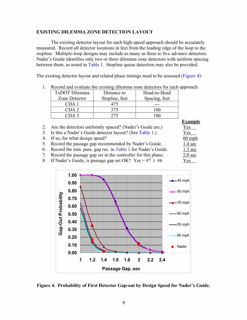
The existing detector layout for each high-speed approach should be accurately measured. Record all detector locations in feet from the leading edge of the loop to the stopline. Multiple-loop designs may include as many as three to five advance detectors. Nader’s Guide identifies only two or three dilemma zone detectors with uniform spacing between them, as noted in Table 1. Stopline queue detection may also be provided. The existing detector layout and related phase timings need to be assessed (Figure 4): 1. Record and evaluate the existing dilemma zone detectors for each approach:
TxDOT Dilemma Zone Detector
Distance to Stopline, feet
Head-to-Head Spacing, feet
CDA 1 475 --- CDA 2 375 100 CDA 3 275 100
Example 2. Are the detectors uniformly spaced? (Nader’s Guide are.) Yes 3. Is this a Nader’s Guide detector layout? (See Table 1.) Yes 4. If so, for what design speed? 60 mph 5. Record the passage gap recommended by Nader’s Guide. 1.4 sec 6. Record the min. pass. gap rec. in Table 1 for Nader’s Guide. 1.5 sec 7. Record the passage gap set in the controller for this phase. 2.0 sec 8. If Nader’s Guide, is passage gap set OK? Yes = #7 ≥ #6 Yes
0.000.100.200.300.400.500.600.700.800.901.00
1 1.2 1.4 1.6 1.8 2 2.2 2.4
Passage Gap, sec
Gap
-Out
Pro
babi
lity
45 mph
50 mph
70 mph
65 mph
55 mph
60 mph
Nader
Figure 4. Probability of First Detector Gap-out by Design Speed for Nader’s Guide.

10
If the existing multiple loop detector design is not from Nader’s Guide, but it is uniformly spaced, then calculate the critical gap-out time from:
sec36.1)7*360(*467.1
)22375475()*3(*467.1)2221(sec,
%85
=−−−
=−−−
=σV
CDACDApCritPassGa
where CritPassGap = minimum passage gap that will hold the 15th percentile approach speed across TxDOT’s first two detectors (CDA 1 and CDA 2), sec; V85% = 85th percentile approach speed, mph; and σ = standard deviation of approach speeds, ≅ 7 mph. or assess the probability of unexpected gap-out over the spacing, knowing the mean and standard deviation of approach speeds, and now the critical speed, CritSpeed, from:
mphPassGap
CDACDAmphCritSpeed 6.260.2
78*682.0)2221(*682.0, ==−−
=ϕ
Microsoft™ Excel spreadsheets provide convenient assessment of the probability of any approach vehicle, chosen at random from a normal distribution, not exceeding the critical speed. Here, Excel shows that the probability (V<26.6, 53, 7) = 0.000. Clearly, no vehicle should gap out between these detectors when a 2.0 second passage gap is used for controlling the related signal phase. Passage gaps set in the controller for uniformly spaced detector plans should not produce gap-out probabilities exceeding 0.01, but they also should not be extra long. For a 78-foot clear space between presence detections, a 1 percent gap-out rate would be produced by a speed of 36.7 mph which will just hold a phase against a passage gap of 1.45 seconds. This could be determined using Excel from:
sec5.1sec45.18.53
787.36*467.1
2221sec,
7.36)7,53(01.0Pr,
⇒==−−
=
⇒==≈=⇒
fpsftCDACDACritGap
mphNobmphCritSpeed σµ
If the multiple-loop detector layout has variable spacing (e.g., a legacy Bierele [7] layout in Texas) then check the first spacing (it will be the largest) against the critical speed and probability distribution, as shown above, to assess the likelihood of vehicles gapping out between the CDA1 and CDA 2 detectors.
APPROACH ROADWAY GEOMETRY
Basic features of the approach roadway geometry are needed, and these data should be verified by site investigations. It is assumed that as-built roadway design plans

11
for the highway are available. Locate the existing detectors on a copy of the plan sheet. The following specific roadway geometry data per approach are needed, as a minimum:
• number of approach lanes, and type of roadway (divided, undivided); • average approach grade for the last 1000 feet to the intersection; • design speed of highway; and • proposed pavement rehabilitation over the next 5 years.
APPROACH ROADWAY SUMMARY
The data collected for the proposed AWEGS design should be summarized into a plan view for each approach. Figure 5 depicts an example for the eastbound direction of a hypothetical 60 mph four-lane divided highway on level grade. Also shown in Figure 5 are two pairs of AWEGS speed-trap detectors (known as ADA and BDA) and two W3-4 advance warning signs, later designed and located, for reference.
Eastbound Approach(60 mph on Level Grade)
N
275′375′475′775′
Existing W 3-3 with flashers
Proposed AWEGS ADA and BDA detectors leading edge at (875′ and 845′)
W3-4 signs (475′)
US 190
FM 4
7
24′
Figure 5. Summary of Existing Conditions of High-Speed Approach and Proposed Layout of AWEGS Detectors and Signs.


13
CHAPTER 3. DESIGN OF AWEGS
DESIGN PROBLEM
A system for providing advance warning for end-of-green must be designed to reliably perform its mission. AWEGS must first detect distant (800-1100 feet away) arriving traffic just as a traffic-actuated signal does. It also must monitor within the local signal cabinet almost all traffic detections and signal status inputs that the existing controller sees. It must provide timely advance warning outputs to the distant (300-600 feet) AWEGS signs. And finally, it should provide a reliable backup flasher assembly in case of control system failure. Other features, such as performance surveillance of red-light-running and remote monitoring capabilities by PC Anywhere telephone dial-up, were provided in recent AWEGS research systems (2), but they are not considered minimum AWEGS design requirements. An overview of the general features and flow of the first AWEGS is presented in Figure 6. The form and function of the computer and related electrical wiring interface terminals shown in Figure 6 and located in the signal cabinet are expected to change over time into a smaller and more simplified design. In the future, the entire AWEGS control system could be fully integrated within an attached programmable computer card (8).
SIGN DESIGN
Passive W3-4 Advance Traffic Control signs (see Section 2C.26 of the 2000 MUTCD, 4) supplemented by warning beacons were used by TTI researchers (2) at two sites to provide approaching motorists advance warning for end-of-green. TxDOT’s Sign Crew Field Book (9) and the relevant sections in the state (10) and national MUTCD (4) should always be consulted for official design requirements and guidance. All aspects of the signs noted in this section are in compliance with the 2003 Texas MUTCD (10). A relevant Standard of the 2003 Texas MUTCD (10) regarding this design should be noted here: “Standard: When a BE PREPARED TO STOP sign (W3-4) is used in advance of traffic signals, it shall be used in addition to a Signal Ahead sign. (W3-3) In both field trials of AWEGS, W3-3 signs were already in place near the AWEGS ADA/BDA detectors. The W3-3 signs are not specifically identified as being a part of AWEGS. In Waco, TxDOT had not attached flashing beacons to the existing W3-3 signs; whereas, at the four-lane divided Brenham site, two W3-3 signs per approach were already in place, with two vertically-mounted beacons per sign constantly flashing in an alternating mode of display. These existing advance warning beacons mounted with the W3-3 signs were recommended by TTI to be turned off during all AWEGS studies. Nighttime viewing suggests that this was the correct decision, given that the AWEGS beacons located with its W 3-4 signs remain off until activated for warning.

14
Figure 6. Design Features and Flow of Advance Warning for End-of-Green System (AWEGS).

15
Features
At the site near Waco, a single ground-mounted W3-4 sign was provided for each approach. Design features of this W3-4 sign were shown in Figure 1a and included:
• screw-in pole foundation; • vertically-mounted 12-inch LED flashing beacon; assembly (RFBA-98); • 50/50 flashing (on/off) cycle (0.50 second/0.50 second), and computer driven; • 7-inch series D black lettering on 48-inch x 48-inch high-intensity yellow
sheeting. Layout is equivalent to CW 21-8 construction warning sign; and • When Flashing 36-inch x 24-inch plaque with 6-inch Series D legend.
At the four-lane divided highway study site in Brenham, as shown in Figure 1b, a ground-mounted W3-4 sign was located on each side of the approach roadway. Dual flashing W3-3 Signal Ahead signs preceded these signs in time and space. Design features of the AWEGS W3-4 sign shown in Figure 1b included:
• cast-in-place pole foundations (Type 24-A); • two horizontally-mounted 12-inch LED flashing beacons assembly (RFBA-98).
Due to local vertical curves, beacons mounted at 10 and 2 o’clock positions horizontally above the sign;
• 41/59 flashing (0.45/0.65) cycle, all beacons flash together, computer driven; • 7-inch series D black lettering on 48-inch x 48-inch high-intensity yellow
sheeting. Layout is equivalent to CW 21-8 construction warning sign; and • When Flashing 36-inch x 24-inch plaque with 6-inch Series D legend.
More visually attractive advance warning signs could readily be used in AWEGS using basic on/off switch control. An example could include overhead cantilevered electronic matrix signs, similar to the one installed in Marshall, as shown in Figure 2. This type of sign support structure would appear justified for high-speed, multilane roads having two-way left-turn lanes, or no (adequate) median divider. This large high target value sign, mounted over the running lanes, would appear to be equivalent to two ground-mounted signs posted on either side of the running lanes, as depicted in Figure 1b in Brenham. Less costly overhead designs using rigid mast-arm mounting or dual-span wire designs for mounting W3-4 signs with warning beacons have also been used around the country. Draft materials for the federal Series 2000 Standard Alphabet indicate that 6C, 8C, and 9C legends (3-line BE PREPARED TO STOP) will be recommended for similar 36-, 48- and 60-inch square construction warning signs.
Location
Two AWEGS-related sign location problems need to be addressed. One is the station along the highway where the W3-4 sign is to be positioned. The second identifies the target location along the approach roadway where the flashing beacons should be targeted. The AWEGS W3-4 sign should be located along the roadway where the ITE-

16
based stopping distance to the onset of the yellow signal exists, based on serving the 85 percentile approach speed, from:
)(2
*151.2**467.1
285
8543 gGdV
TVX W ±+=−
where: =−43WX ITE-based stopping distance, feet; 85V = 85th percentile approach (design) speed, mph; T = perception-reaction to yellow onset, 1.0 sec; d = maximum usual (ITE) stopping deceleration rate, 10 fps2 ; g = gravity, 32.2 fps2 ; and
G = roadway grade, decimal equivalent. Since the above stopping distance is about the same as that recommended for the leading detector (CDA1) in Nader’s Guide, the practical location of the W3-4 sign is near the location of the first dilemma zone detector given in Nader’s Guide. This similarity assumes that the approach speed now existing (as determined from a spot-speed survey) is similar to the design speed used to select the detector layout from Nader’s Guide. Local site adjustments of ± 50 feet to avoid driveways, etc are considered acceptable in locating the W3-4 sign. An Excel spreadsheet is provided, as will be illustrated later, that conveniently calculates these design requirements. The focal point of all flashing beacons for an approach is the same. The target location shall be (the drivers’ eyes) the centerline of the approach roadway at the location of the ADA advance detector described later in this chapter. Field experience suggests that correctly targeting these beacons must be given high priority, and subsequent field inspection of their targeting during and after construction is imperative. Field observations indicate that several problems may arise during installation. The beacons may be misaligned during initial setup, perhaps due to the approach road vertical curvature. They may later become misaligned due to temperature changes and wind-induced vibrations, if their mountings are not secure. LED beacons tend to have a relatively narrow angle of focus, and their apparent brightness will not be high or uniform unless they are always targeted at the same point on the approach roadway. This is especially true if two signs are used per approach, one on each side of four-lane divided roadways.
Electrical
The assembly of AWEGS W3-4 signs shown in Figure 1 is relatively simple. Power is required to drive only the LED flashing beacons and is provided from the signal cabinet by the AWEGS computer/terminal switches. Thus, 120 VAC electrical power and control of the sign beacons are combined using a 3-conductor #12 AWG IMSA 20-1 signal cable, or equivalent. Since the sign is strategically located close to the existing dilemma zone detectors, electrical ground boxes and conduit should already be in place
17
which may expedite the cable run to the signal cabinet. Wireless communications to these signs would not appear cost-effective for existing systems at this time.
ADVANCE WARNING DETECTORS
Two advance warning detectors are added to existing signal control systems per approach to serve three functions in AWEGS. They provide a more distant look into the future regarding the nature of arriving traffic than is typically provided (or needed) by dilemma zone detectors (Nader’s Guide). They also form a well-defined speed trap to better estimate the arrival time of each and every vehicle to the first downstream dilemma zone detector. Lastly, they are used to classify the type of vehicle into car or truck categories. Knowing the type of vehicle and its speed, AWEGS estimates its arrival in real time (2). The design, location, and construction of the advance speed-trap detectors are critical to the successful operation of AWEGS. Inductive-loop detectors (ILD) are currently recommended for AWEGS applications based on field experience with their operational measurement precision, dependability, and technology requirements. Wireline communication is also recommended due to its dependability, although wireless technology is advancing rapidly. Long home-runs (some over 1000 feet long) to the signal cabinet offer design challenges, but modern ILDs seem to have little problem working as specified when the ILD system is well designed and constructed. In AWEGS design, the two ILD speed-trap detectors are called the ADA and BDA detectors. As noted in Figure 5, ADA is the leading detector and BDA is the trailing detector of the speed trap. Both detectors operate in the presence mode of detection. Both ILD detectors shall be 6-foot x 6-foot inductive loop detectors.
Location
The leading edge of the ADA detector provides AWEGS with the first indication of the arrival of a vehicle. AWEGS begins a process of responding to this vehicle as it travels across the ADA detector and then arrives at the BDA detector. A typical travel time between these two arrival events is on the order of 0.3 second or so. The activation presence of the ADA detector is also monitored by AWEGS as the vehicle travels over the ADA detector. By strategically placing the leading edge of the BDA detector 30 feet downstream from the leading edge of the ADA detector, providing a 24-foot gap between them, a car will leave the ADA detector (lose its presence) before reaching the BDA detector, but a truck will still have its presence noted on the ADA detector. Thus, AWEGS can distinguish a car (ADA off, BDA on) from a truck (ADA on, BDA on) as the vehicle arrives on the BDA detector and can also easily determine its speed. Research indicates that trucks have more difficulty stopping than cars. The literature suggests that the maximum acceptable deceleration rate for a typical truck to stop is 70 to 80 percent of that for a car (2, 5).

18
How much advance warning distance and time are needed? AWEGS design specification provides a car with enough distance (and time) to permit the 99th percentile approach speed car (probably going at an illegal high speed) to slow down to the design speed of the downstream dilemma zone detectors (CDA) at the leading edge of the first dilemma zone detector (CDA1). Another way of saying this is that AWEGS provides the 99th percentile approach speed vehicle (car) with enough warning that it could safely stop if and when the downstream red signal is displayed, assuming ITE’s base deceleration rate. An equation to calculate this location for the ADA detector is:
43
2%85
2%99
43%99 )(2)(*151.2
**467.1 −− +±
−+= WW X
GgdVV
TVADA
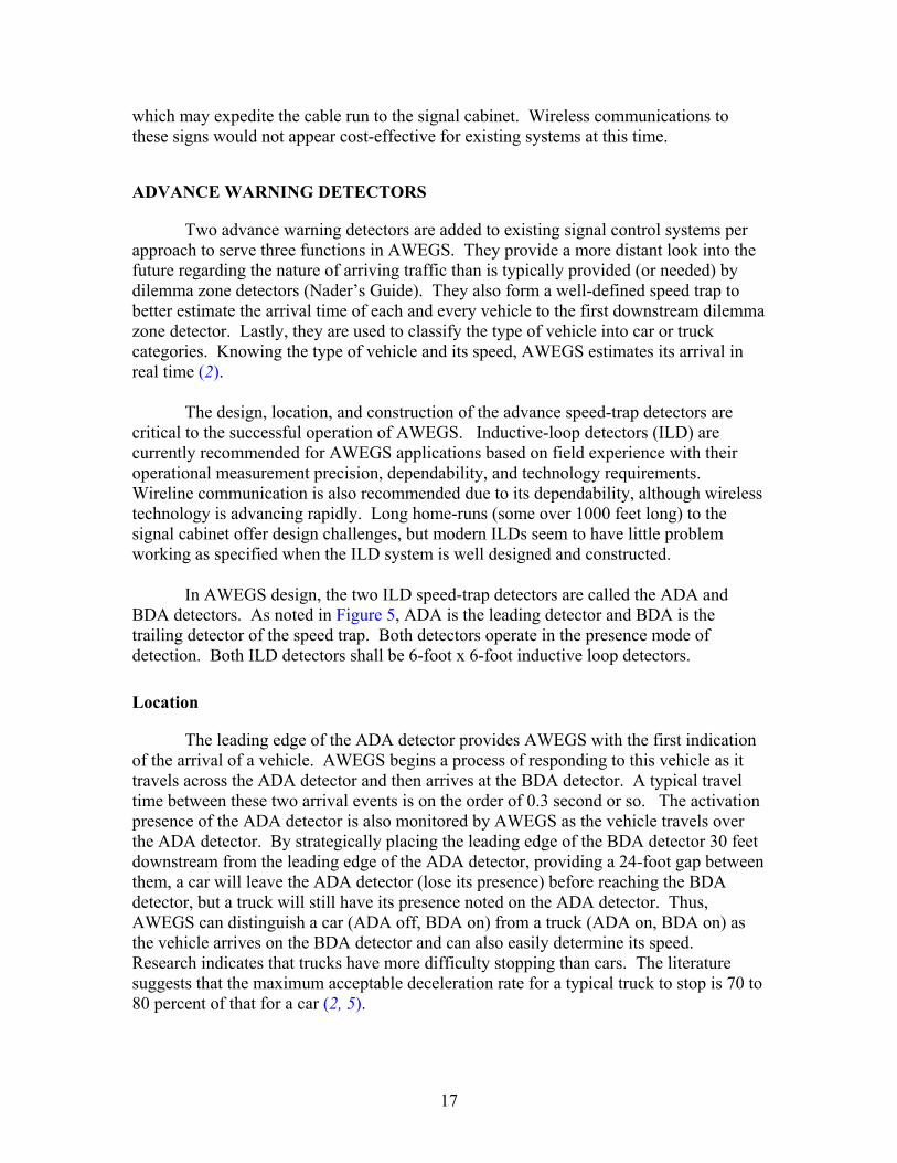
where the new terms are: ADA = leading edge of the ADA advance warning detector, feet; %99V = 99th percentile speed 9*3.1 85%85%99 +≅+= VVV σ , mph; and 43−WT = input-perception-read-reaction to W3-4 flasher and decision to slow. Time is = 2.7 sec = 0.2 sec + 2.5 sec. Several factors increase the distance the ADA detector should be from the stopline. Increasing speed increases the stopping distance. Increasing downgrade to the intersection (-G) increases the stopping distance. An AWEGS requirement is that the flasher must always display a full-on period within 0.2 seconds of the time a vehicle is detected arriving at the ADA detector. Surprisingly, the detection-response time of 0.2 seconds is not the real challenge. The real challenge is to always get the “full on” flash time. No off-the-shelf flasher could be found in the signal industry that could reliably provide this desired feature. Only expensive microprocessor-based programmable timers could. Thus, the AWEGS computer is routinely used to drive the flashers to get the desired initial full-on flash. As noted above, the BDA detector is located 30 feet downstream of the ADA detector. Thus, the relative location of the leading edge of the BDA detector is: feetADABDA 30−= A graphical summary of the above results is presented in Figure 7 for level grades. Also shown in Figure 7 are the windows for locating various signs, as defined by TxDOT’s Sign Crew Field Book (9). The Texas MUTCD required W3-3 Signal Ahead Sign is indicated to be placed some 975 to 1150 feet from the intersection for approach speeds of 45 mph or more. A space window of opportunity is provided by the Sign Crew Field Book (SCFB) for future signs, such as the new W3-4 sign used by AWEGS, in the range of 325 to 500 feet from the intersection for speeds of 45 mph or more. The new AWEGS sign will conveniently fit into this “space” until the approach speeds reach 65 mph, where some readjustment of signage may be needed. Table 2 provides a tabular summary of the sign and detector location results shown in Figure 7.
19
300
400
500
600
700
800
900
1000
1100
1200
45 50 55 60 65 70
Design (Approach) Speed, mph
Trav
el D
ista
nce
to S
topl
ine,
feet
W 3-3 /SCFB
W 3-3 /SCFB
ADA /AWEGS
BDA /AWEGS
W 3-4 +CDA1/Naderspace /SCFB
space /SCFB
Figure 7. Distance to the Stopline for ADA, BDA and CDA1 Detectors (from Nader’s Guide) as Related to Design (85th percentile) Speed for Level Grades.
Table 2. Locations of AWEGS Advance Speed-Trap Detectors and W3-4 Sign for Level Grade Using Nader’s Guide for Dilemma Zone Detection.
Design or Approach Speed,
mph
AWEGS ADA Detector,
feet
AWEGS BDA Detector,
feet
Sign W3-4 @ CDA 1 Detector of Nader’s Guide, feet
45 595 565 330 50 683 653 350 55 776 746 415 60 875 845 475 65 979 949 540 70 1089 1059 600
20
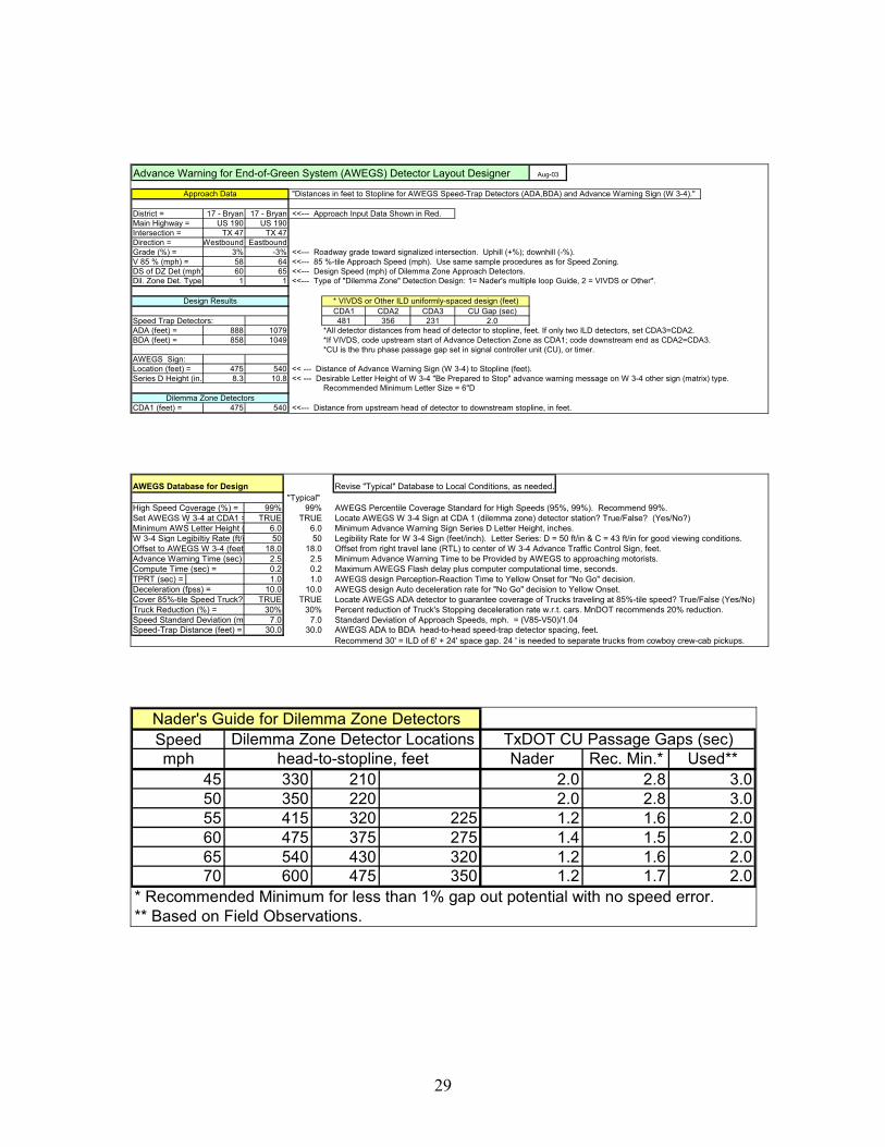
Spreadsheet
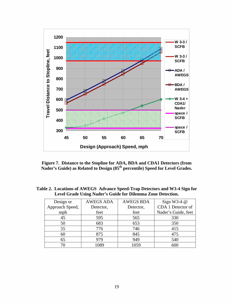
An Excel spreadsheet, named AWEGS Designer, has been prepared to help users solve this design problem for a given data set. Users can readily examine several design options and assess the effects of roadway grade, requirements for handling of high-speed trucks, impacts of high variance in traffic speeds, and existing detector design speed not being the same as the measured approach speed. Moreover, the designer may or may not wish to set the W3-4 sign at the CDA1 detector for various reasons. Guidance is also provided on desirable sign letter size, which varies with critical advance detection zone location and where the W3-4 sign is to be placed. In addition, graphic plots of the effects of changes in passage gaps in the controller are shown. Printouts can be made to provide engineering file documentation. The AWEGS Designer Excel program can be obtained on the internet at http://tti.tamu.edu/documents/0-4260-2/. An example of an AWEGSDesigner application is shown in Figure 8 below for 60 and 65 mph (Nader’s Guide) design speeds. The appendix provides more details of AWEGS Designer, including descriptions and recommendations for values of characteristic input data.
District = 17 - Bryan 17 - BryanMain Highway = US 190 US 190Intersection = TX 47 TX 47Direction = Westbound EastboundGrade (%) = 3% -3%V 85 % (mph) = 58 64DS of DZ Det (mph) = 60 65Dil. Zone Det. Type = 1 1
Speed Trap Detectors:ADA (feet) = 888 1079BDA (feet) = 858 1049
AWEGS Sign:Location (feet) = 475 540Series D Height (in.) = 8.3 10.8
CDA1 (feet) = 475 540CDA2 (feet) = 375 430CDA3 (feet) = 275 320
AWEGS DESIGNER
Dilemma Zone Detectors
Design Results
Approach Data
Figure 8. Example of Sheet 1 from AWEGS Designer.
21
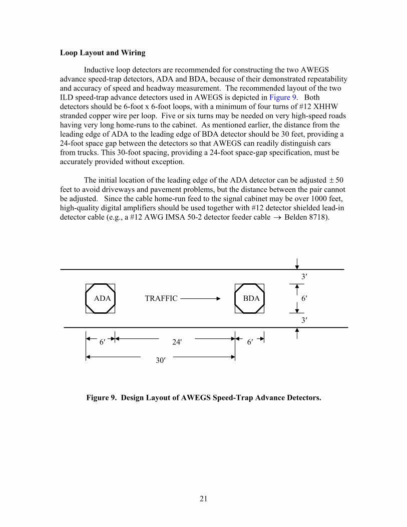
Loop Layout and Wiring
Inductive loop detectors are recommended for constructing the two AWEGS advance speed-trap detectors, ADA and BDA, because of their demonstrated repeatability and accuracy of speed and headway measurement. The recommended layout of the two ILD speed-trap advance detectors used in AWEGS is depicted in Figure 9. Both detectors should be 6-foot x 6-foot loops, with a minimum of four turns of #12 XHHW stranded copper wire per loop. Five or six turns may be needed on very high-speed roads having very long home-runs to the cabinet. As mentioned earlier, the distance from the leading edge of ADA to the leading edge of BDA detector should be 30 feet, providing a 24-foot space gap between the detectors so that AWEGS can readily distinguish cars from trucks. This 30-foot spacing, providing a 24-foot space-gap specification, must be accurately provided without exception. The initial location of the leading edge of the ADA detector can be adjusted 50± feet to avoid driveways and pavement problems, but the distance between the pair cannot be adjusted. Since the cable home-run feed to the signal cabinet may be over 1000 feet, high-quality digital amplifiers should be used together with #12 detector shielded lead-in detector cable (e.g., a #12 AWG IMSA 50-2 detector feeder cable → Belden 8718).
Figure 9. Design Layout of AWEGS Speed-Trap Advance Detectors.
ADA BDA
3′
6′
3′
30′
24' 6′ 6′
TRAFFIC

22
SYSTEM
The AWEGS computer system is located in the local intersection signal cabinet. AWEGS detects and classifies approaching vehicles as either cars or trucks using the upstream speed-trap detectors, monitors the actuations within the local signal cabinet, including stop-bar detectors, phase status, and dilemma zone detectors, and provides timely advanced warning outputs to the AWEGS signs. The AWEGS consists of an environmentally hardened industrial-grade computer, a backup flasher panel with watchdog maximum flash timers, two timer relays to disconnect the phase holds, and interface terminals/connections. Figure 6 illustrates the components of the system, whose further description and applications follow.
Cabinet
Since the AWEGS computer system is located in an existing signal cabinet, a large TS-2 compatible base-mounted cabinet is desired. Special ventilation may be required to provide maximum acceptable cabinet temperature during the summer. Two ventilation fans with separate 95 oF and 105 oF thermostats may be required to minimize maximum temperatures in the cabinet.
Computer
An environmentally hardened industrial-grade PC is currently used to run the AWEGS. The industrial PC used is manufactured by Kontron America and includes an Intel 850 MHz single board computer, 40 gigabyte hard disk, and two National Instrument’s digital I/O cards (NIDAQ 6527) with 24 inputs and 24 outputs each. The NIDAQ cards are used to monitor the actuations of the advance speed-trap detectors. The NIDAQ cards are also used to monitor the status of the main-street phases, stop-bar detectors, dilemma zone detectors, and the controller ring status bits (3 bits: A, B, and C per ring) through contact closure connections on the signal cabinet’s back-panel. The large hard disk was necessary to store log files collected to evaluate and analyze the system performance during research and development. Future system data storage requirements should be much lower and electrical interfaces simpler. Future AWEGS designs should not need the power available in the currently used industrial PC. The final system could run on a much smaller industrial microcontroller. TTI researchers have also identified another alternative for getting the inputs needed by the AWEGS from the signal cabinet, especially for TS-2 cabinets. Instead of using the NIDAQ cards to get the contact-closure actuations from the signal cabinet’s back-panel, serial Bus Interface Units (BIUs) could be used to replace the existing BIU’s 1, 2, 3, and 4 in the TS-2 signal cabinet, and the AWEGS would get its needed inputs by communicating with the serial BIUs over a serial connection. That is, the two NIDAQ cards and complex interface wiring would be replaced with four serial cables.

23
Software Flasher System
The software flasher system uses four solid-state relays whose on/off input signal is controlled by the AWEGS. When AWEGS turns on one of the four outputs, an output signal of 24 VDC is supplied by the computer to the designated optically isolated input of a solid-state relay, causing the output of that interface relay to supply 120 VAC to the selected approach warning beacon(s) (but not necessarily all). By precisely switching the relays alternately on and off, AWEGS creates a software flasher with the desired 50-percent duty cycle. The design output should be 0.50 seconds on and 0.50 seconds off, providing a cycle time of 1.00 seconds. Note that the first and immediate response of the flasher shall be the onset of the full 0.50 second “on” phase for the primary (top or inside) beacons of the sets of two. When two W3-4 signs are placed on opposite sides of a four-lane divided road, it is recommended that all four beacons (two for each sign, horizontally mounted) flash simultaneously. Current signal flashers operate continuously and cannot provide the desired immediate and full-on phase because the on command from AWEGS comes randomly and, thus, partial on/off flashes would result using off-the-shelf flashers. Advance warning time is critical in AWEGS and should not be compromised. This desired flasher function is not easy to provide and may require using microprocessor-based technology.
Backup/Watchdog Flasher
When AWEGS is running, its computer changes an output on the digital output interface from high to low voltage every 2 seconds. The (digital output) heartbeat is connected to the reset terminal of the timer relay that is set to countdown to 3 seconds. The heartbeat signal causes the timer relay to reset its countdown time back to zero whenever the voltage state changes to low. Whenever the heartbeat is not present for 3 seconds, the timer relay’s normally open contacts, which are currently closed, switch open. This action disconnects the software flasher system and connects the backup flasher system. At the same time, another set of normally open contacts in the timer relay switch closed, disconnecting the logic common for the software flashers. When the backup flasher system activates due to loss of heartbeat signal, phases having the approach beacons continue flashing independently whenever those phases are either red or yellow. The optically isolated inputs of the four 120 VAC input solid-state relays constantly monitor the status of the load switches for the phases yellow or red signal lights. When the backup system is activated, the timer relay’s normally closed contact powers the 120 VAC output supply voltage of the solid-state relays monitoring the load switches. When any one of the four solid-state relay’s inputs is supplied with 120 VAC from a load switch, the relay supplies 120 VAC to the appropriate solid-state double-pole flasher connected to the flasher beacon associated with that particular phase. If and when the heartbeat is restored, the timer relay disconnects the backup flasher system power supply and reconnects the AWEGS software flashers 120 VAC power supply and logic common connection.
24
The backup system will also flash the beacons when the cabinet is in cabinet flash, when the malfunction management unit (MMU) detects a malfunction or if the power to the flash transfer relay’s input is not present for any reason, for example a loss of power to the rest of the cabinet. The mechanical relay’s 120 VAC input is supplied from the same source as the flash transfer relay’s input source. When 120 VAC input is not present on the relay’s input, due to a fault condition or loss of power, the normally closed contacts in the mechanical relay power both solid-state, two-pole flashers. The backup flasher system’s control logic was created by combining the inputs and outputs of four solid-state relays with one mechanical relay and one timer relay.
Timer Relay for Phase Holds
Two IDEC GT3D-4AD24 electronic timer relays are used to disconnect the phase hold signal from the AWEGS in case of a malfunction in the system. The timer relay is set to mode 3C on the operation mode selector and 8 seconds of delay on the time-setting digital switch. In this mode, the relay starts counting down when a phase hold signal is applied. The phase hold signal passes through closed contacts in the timer relay. If the phase hold signal continues longer than 8 seconds, the timer relay times down from 8 to 0 seconds and then opens the contacts, dropping the phase hold. If the phase hold signal does not last for more than 8 seconds, then nothing happens. The relay resets back to 8 seconds whenever the AWEGS drops the phase hold signal. Two timer relays work independently, one for each phase hold.
Resistor Input Interface Circuit for NIDAQ 6527
The interface circuit consists of a double-layer IDEC terminal strip with 24 individual terminals. A bus connecting all 24 bottom level terminals supplies all 24 16K-ohm resistors with 24 VDC. The supply to the bus is fused by a 1/5 amp fuse to protect the output of the traffic signal controller. The current flowing (leaking) through each resistor is approximately 1mA when the output from the traffic signal controller is active low on a particular output. Each input for the DAQ card requires 1mA for the DAQ card’s optical isolator’s LED to work reliably. The path the current flows is from the 24 VDC supply through the fuse then to the resistor and into the DAQ optical isolator then out of the DAQ and into the output of the traffic signal controller. Current sinks into the output only when the output of the traffic signal controller is active low.

25
REFERENCES 1. Sunkari, S.R., Messer, C.J., Charara, H.A., and Parker, R.T. Signal Technician’s
Installation and Maintenance Manual for Advance Warning for End-of-Green Phase at High Speed Traffic Signals. Texas Transportation Research Report 4260-3, September 2003.
2. Messer, C.J., Sunkari, S.R., Charara, H.A, and Parker, R.T. Development of Advance
Warning Systems for End-of-Green Phase at High Speed Traffic Signals. Texas Transportation Research Report 4260-4, September 2003.
3. Detector Chapter/Applications Manual. (draft) Traffic Operations Division-Traffic
Management Section, Texas Department of Transportation, Austin, Texas, circa 1996.
4. Manual on Uniform Traffic Control Devices. U.S. Department of Transportation,
Washington, D.C., December 2000. 5. Hughes, P. Guidelines for the Installation of Advanced Warning Flashers. Technical
Memorandum, Engineering Services Division, Minnesota Department of Transportation, August 28, 2000.
6. Procedures for Establishing Speed Zones. Texas Department of Transportation,
August 2000. 7. Manual of Traffic Signal Design. Institute of Transportation Engineers, Second
Edition, 1991, p. 86. 8. Livolsi, P.C. “Another Method of Dilemma Zone Protection.” IMSA Journal.
July/August 2001, pp. 44-46. 9. Sign Crew Field Book. 2nd Edition. Traffic Operations Division. Texas Department
of Transportation, Austin, Texas, April 1998. 10. Texas Manual on Uniform Traffic Control Devices. Texas Department of
Transportation, Austin, Texas, 2003.

27
APPENDIX
EXAMPLE SPREADSHEET OF AWEGS DESIGNER

29
Advance Warning for End-of-Green System (AWEGS) Detector Layout Designer Aug-03
"Distances in feet to Stopline for AWEGS Speed-Trap Detectors (ADA,BDA) and Advance Warning Sign (W 3-4)."
District = 17 - Bryan 17 - Bryan <<--- Approach Input Data Shown in Red.Main Highway = US 190 US 190Intersection = TX 47 TX 47Direction = Westbound EastboundGrade (%) = 3% -3% <<--- Roadway grade toward signalized intersection. Uphill (+%); downhill (-%).V 85 % (mph) = 58 64 <<--- 85 %-tile Approach Speed (mph). Use same sample procedures as for Speed Zoning.DS of DZ Det (mph) 60 65 <<--- Design Speed (mph) of Dilemma Zone Approach Detectors.Dil. Zone Det. Type 1 1 <<--- Type of "Dilemma Zone" Detection Design: 1= Nader's multiple loop Guide, 2 = VIVDS or Other*.
CDA1 CDA2 CDA3 CU Gap (sec)Speed Trap Detectors: 481 356 231 2.0ADA (feet) = 888 1079 *All detector distances from head of detector to stopline, feet. If only two ILD detectors, set CDA3=CDA2. BDA (feet) = 858 1049 *If VIVDS, code upstream start of Advance Detection Zone as CDA1; code downstream end as CDA2=CDA3.
*CU is the thru phase passage gap set in signal controller unit (CU), or timer.AWEGS Sign:Location (feet) = 475 540 << --- Distance of Advance Warning Sign (W 3-4) to Stopline (feet).Series D Height (in.) 8.3 10.8 << --- Desirable Letter Height of W 3-4 "Be Prepared to Stop" advance warning message on W 3-4 other sign (matrix) type.
Recommended Minimum Letter Size = 6"D
CDA1 (feet) = 475 540 <<--- Distance from upstream head of detector to downstream stopline, in feet.
* VIVDS or Other ILD uniformly-spaced design (feet)
Dilemma Zone Detectors
Design Results
Approach Data
Revise "Typical" Database to Local Conditions, as needed."Typical"
High Speed Coverage (%) = 99% 99% AWEGS Percentile Coverage Standard for High Speeds (95%, 99%). Recommend 99%.Set AWEGS W 3-4 at CDA1 = TRUE TRUE Locate AWEGS W 3-4 Sign at CDA 1 (dilemma zone) detector station? True/False? (Yes/No?)Minimum AWS Letter Height ( 6.0 6.0 Minimum Advance Warning Sign Series D Letter Height, inches.W 3-4 Sign Legibiltiy Rate (ft/i 50 50 Legibility Rate for W 3-4 Sign (feet/inch). Letter Series: D = 50 ft/in & C = 43 ft/in for good viewing conditions.Offset to AWEGS W 3-4 (feet 18.0 18.0 Offset from right travel lane (RTL) to center of W 3-4 Advance Traffic Control Sign, feet.Advance Warning Time (sec) 2.5 2.5 Minimum Advance Warning Time to be Provided by AWEGS to approaching motorists.Compute Time (sec) = 0.2 0.2 Maximum AWEGS Flash delay plus computer computational time, seconds.TPRT (sec) = 1.0 1.0 AWEGS design Perception-Reaction Time to Yellow Onset for "No Go" decision.Deceleration (fpss) = 10.0 10.0 AWEGS design Auto deceleration rate for "No Go" decision to Yellow Onset.Cover 85%-tile Speed Truck? TRUE TRUE Locate AWEGS ADA detector to guarantee coverage of Trucks traveling at 85%-tile speed? True/False (Yes/No)Truck Reduction (%) = 30% 30% Percent reduction of Truck's Stopping deceleration rate w.r.t. cars. MnDOT recommends 20% reduction.Speed Standard Deviation (m 7.0 7.0 Standard Deviation of Approach Speeds, mph. = (V85-V50)/1.04Speed-Trap Distance (feet) = 30.0 30.0 AWEGS ADA to BDA head-to-head speed-trap detector spacing, feet.
Recommend 30' = ILD of 6' + 24' space gap. 24 ' is needed to separate trucks from cowboy crew-cab pickups.
AWEGS Database for Design
Speedmph Nader Rec. Min.* Used**
45 330 210 2.0 2.8 3.050 350 220 2.0 2.8 3.055 415 320 225 1.2 1.6 2.060 475 375 275 1.4 1.5 2.065 540 430 320 1.2 1.6 2.070 600 475 350 1.2 1.7 2.0
* Recommended Minimum for less than 1% gap out potential with no speed error.** Based on Field Observations.
head-to-stopline, feetDilemma Zone Detector Locations
Nader's Guide for Dilemma Zone DetectorsTxDOT CU Passage Gaps (sec)

30
Probability of Premature Gap Out for Passage Gaps by Detector Design Speed with no Speed Error
0.00.10.20.30.40.50.60.70.80.91.0
1 1.2 1.4 1.6 1.8 2 2.2 2.4 2.6 2.8 3
Passage Gap (sec)
Prob
abili
ty o
f Gap
Out 45 mph
50 mph
70 mph
55 mph
65 mph
60 mph