design and implementation of eight-legged robotic transporter
TRANSCRIPT
DESIGN AND IMPLEMENTATION OF EIGHT-LEGGED ROBOTIC
TRANSPORTER
A Thesis
presented to
the Faculty of California Polytechnic State University,
San Luis Obispo
In Partial Fulfillment
of the Requirements for the Degree
Master of Science in Mechanical Engineering
by
Jeremy David DePangher
September 2013

ii
© 2013
Jeremy David DePangher
ALL RIGHTS RESERVED

iii
COMMITTEE MEMBERSHIP
TITLE: Design and Implementation of Eight-Legged Robotic
Transporter
AUTHOR: Jeremy David DePangher
DATE SUBMITTED: September 2013
COMMITTEE CHAIR: Saeed Niku, PhD
Professor of Mechanical Engineering
COMMITTEE MEMBER: John Ridgely, PhD
Professor of Mechanical Engineering
COMMITTEE MEMBER: Peter Schuster, PhD
Professor of Mechanical Engineering
iv
ABSTRACT
Design and Implementation of Eight-Legged Robotic Transporter
Jeremy David DePangher
This thesis contains the design, manufacturing, and testing of a functional eight-
legged robotic transporter based on the concept design laid out in U.S. Patent 7,246,671.
The device is intended to achieve three different sequences of motion: regular driving,
obstacle climbing, and stair climbing. The prototype was carried through concept design,
analysis, selection of materials and components, manufacturing, software development,
and final assembly and testing. The device can be assembled under multiple
configurations, which harbor certain advantages and disadvantages. The results of the
testing encourage the continuation of a second iteration of this concept.
Keywords: U.S. Patent 7,246,671, functional, eight-legged, robotic, obstacle, stair,
climbing, design, testing, sequence, prototype, configurations.

v
ACKNOWLEDGMENTS
I would like thank my committee for their continued support of my project: Dr.
Saeed Niku, my committee chair; Dr. John Ridgely; and Dr. Peter Schuster. These
individuals aided me each step along the way, and for that I am very grateful.
My project would not have been possible without the financial support and
encouragement of my sponsor, Mr. Michael Goren.
I would also like to acknowledge the technicians at the Mustang ’60 machine
shop for their help in manufacturing many of the parts necessary for the completion of
this project.
Lastly, I would like to thank my family and friends for the motivation to see this
project to completion.

vi
TABLE OF CONTENTS
LIST OF TABLES ........................................................................................................... viii
LIST OF FIGURES ........................................................................................................... ix
CHAPTER
1. INTRODUCTION ........................................................................................................ 1
1.1. Background ............................................................................................................. 1
1.2. Patent....................................................................................................................... 1
1.3. Scope and Objectives .............................................................................................. 2
2. DESIGN AND ANALYSIS ......................................................................................... 5
2.1. Concept ................................................................................................................... 5
2.1.1. Independent Joint Motions ................................................................................ 5
2.1.2. Linear Actuation ............................................................................................... 5
2.1.3. Steering and Driving ......................................................................................... 6
2.1.4. Moving Sequences ............................................................................................ 9
2.2. Mechanical Design................................................................................................ 22
2.2.1. Configuration Options .................................................................................... 23
2.2.2. Analysis........................................................................................................... 29
2.2.3. Component Selection ...................................................................................... 44
2.3. Mechatronics Design ............................................................................................ 51
2.3.1. Linear Actuator Control .................................................................................. 51
2.3.2. Driving and Steering Motor Control ............................................................... 53
2.3.3. Microprocessor Selection................................................................................ 55
2.3.4. Power Supplies................................................................................................ 56
2.3.5. Overall System Configuration ........................................................................ 58
2.3.6. Software .......................................................................................................... 59
2.4. Manufacturing ....................................................................................................... 61
3. TESTING .................................................................................................................... 64
3.1. Plan and Objectives............................................................................................... 64
3.2. Stair Climbing Sequence Tests ............................................................................. 64
vii
3.3. Obstacle Climbing Sequence Tests ....................................................................... 69
4. CONCLUSIONS AND RECOMMENDATIONS ..................................................... 74
BIBLIOGRAPHY ............................................................................................................. 81
APPENDICIES
A: PART DRAWINGS .................................................................................................... 82
B: ENGINEERING CALCULATIONS .......................................................................... 99
C: BILL OF MATERIALS ............................................................................................ 111
D: DATA SHEETS ........................................................................................................ 114
E: SEQUENCE TESTING IMAGES ............................................................................ 117
F: SOFTWARE CODE ................................................................................................. 122

viii
LIST OF TABLES
2.1. Configuration Options for Driving and Steering Motor Pairs ..................................... 7
2.2. Standard Stair Step Sizes ........................................................................................... 13
2.3. Summary of Stair Climbing Sequence ....................................................................... 22
2.4. Variable Inputs for Driving Torque Calculations ...................................................... 31
2.5. Inputs for Drive Motor Mounting Bracket Deflection ............................................... 34
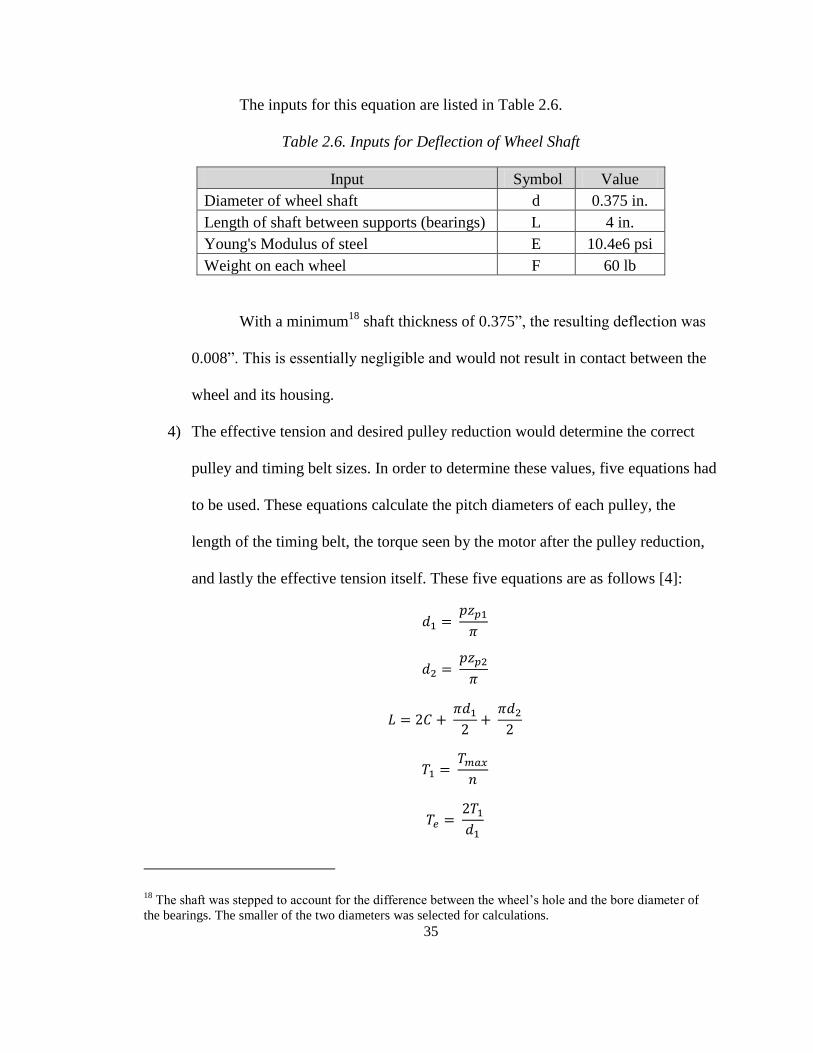
2.6. Inputs for Deflection of Wheel Shaft ......................................................................... 35
2.7. Inputs for Tension and Reduction of Timing Belt ..................................................... 36
2.8. Inputs for Steering Motor Torque .............................................................................. 38
2.9. Inputs for Deflection of Steering Motor Mounting Plate .......................................... 39
2.10. Inputs for Horizontal Support Shaft Deflection ....................................................... 40
2.11. Inputs for Wheel Shaft Press Fit .............................................................................. 41
2.12. Inputs for Actuator Mounting Screw Stress............................................................. 42
2.13. Inputs for Bending Stress in Platform ...................................................................... 43
2.14. Arduino Mega 2560 Pin Usage Breakdown ............................................................ 55
2.15. Current Draw Requirements .................................................................................... 57
2.16. Current Draw for Various Conditions ...................................................................... 57
2.17. Global Variable Declarations ................................................................................... 60
2.18. Function Properties and Descriptions ...................................................................... 61
C.1. Bill of Materials ...................................................................................................... 111
ix
LIST OF FIGURES
1.1 - Concept Sketch Based on Patent Description............................................................. 4
2.1 - Conceptual Platform with Labeled Pairs .................................................................... 8
2.2 - Regular Driving Mode 1 ........................................................................................... 10
2.3 - Regular Driving Mode 2 ........................................................................................... 10
2.4 - Obstacle Climbing Sequence Stage 1 ....................................................................... 11
2.5 - Obstacle Climbing Sequence Stage 2 ....................................................................... 11
2.6 - Obstacle Climbing Sequence Stage 3a ..................................................................... 12
2.7 - Obstacle Climbing Sequence Stage 3b ..................................................................... 12
2.8 - Obstacle Climbing Sequence Stage 4 ....................................................................... 13
2.9 - Device with Critical Climbing Dimensions.............................................................. 14
2.10 - Stage 1 of Climbing Sequence................................................................................ 15
2.11 - Stage 2 of Climbing Sequence................................................................................ 15
2.12 - Stage 3 of Climbing Sequence................................................................................ 16
2.13 - Stage 4 of Climbing Sequence................................................................................ 16
2.14 - Stage 5 of Climbing Sequence................................................................................ 17
2.15 - Stage 6 of Climbing Sequence................................................................................ 18
2.16 - Stage 7 of Climbing Sequence................................................................................ 18
2.17 - Stage 8 of Climbing Sequence................................................................................ 19
2.18 - Stage 9 of Climbing Sequence................................................................................ 20
2.19 - Stage 10 of Climbing Sequence.............................................................................. 20
2.20 - Stage 11 of Climbing Sequence.............................................................................. 21
2.21 - Standard Ball Thrust Bearing ................................................................................. 24
2.22 - Banded Ball Thrust Bearing ................................................................................... 24
2.23 - Turntable Bearing with Assembly .......................................................................... 25
2.24 - Flex Coupling Connection ...................................................................................... 27
2.25 - Wheel Housing with Bearing Pillow Blocks and Wheel ........................................ 28
2.26 - Actuator Tip Being Inserted Into Block to Complete Assembly............................ 29
2.27 - Diagram of Driving Motor Bracket Analysis ......................................................... 33
2.28 - Contact Patch of Drive Wheel ................................................................................ 37
2.29 - Right Angle Geared Motor for Driving .................................................................. 45
2.30 - Inline Geared Motor for Steering ........................................................................... 46
2.31 - HCR112-14-12 Flex Coupling ............................................................................... 48
2.32 - Turntable Bearing ................................................................................................... 48
2.33 - Firgelli Automation FA-400-L-12-30 Linear Actuator .......................................... 49
2.34 - Linear Bearing ........................................................................................................ 50
2.35 - Pololu VNH2SP30 Dual Motor Driver Board ........................................................ 53

x
2.36 - Pololu VNH5019 Single Motor Driver Board ........................................................ 54
2.37 - Arduino Mega 2560 ................................................................................................ 55
2.38 - Electronic Components Assembly Diagram........................................................... 58
2.39 - Frame Base with Opposite-Facing Actuator Slots ................................................. 62
2.40 - Actuator Support..................................................................................................... 63
3.1 - Stage 1 to Stage 2 Transition .................................................................................... 65
3.2 - Completion of Stage 2 .............................................................................................. 66
3.3 - Completion of Stage 9 .............................................................................................. 67
3.4 - Completion of Stage 10 ............................................................................................ 68
3.5 - Rigid Rod Added to Reduce Tilting ......................................................................... 69
3.6 - Vehicle in Position to Begin Stage 1 ........................................................................ 70
3.7 - Completion of Stage 1 .............................................................................................. 70
3.8 - Completion of Stage 2 .............................................................................................. 71
4.1 - Complete Solid Model of 8-Legged Robotic Transporter ........................................ 74
4.2 - Complete 8-Legged Robotic Transporter ................................................................. 75
E.1 - Stair Climbing Stage 1 ........................................................................................... 117
E.2 - Stair Climbing Stage 2 ........................................................................................... 117
E.3 - Stair Climbing Stage 3 ........................................................................................... 118
E.4 - Stair Climbing Stage 4 ........................................................................................... 118
E.5 - Stair Climbing Stage 5 ........................................................................................... 119
E.6 - Stair Climbing Stage 6 ........................................................................................... 119
E.7 - Stair Climbing Stage 7 ........................................................................................... 120
E.8 - Stair Climbing Stage 8 ........................................................................................... 120
E.9 - Stair Climbing Stage 9 ........................................................................................... 121
E.10 - Stair Climbing Stage 10 ....................................................................................... 121

1
1. INTRODUCTION
1.1. Background
This thesis is concerned with the designing, manufacturing, and testing of a
functional prototype based on the concept design laid out in U.S. Patent No. 7,246,671.
This patent, entitled “Stair-climbing human transporter,” is the sole inspiration for the
body of work done in this thesis.
1.2. Patent
According to the patent language, the purpose of this invention is to “transport
persons, robots or cargo, moving on a surface, over obstacles and for ascending and
descending stairs” [1]. There are several aspects of this invention that not only make it
unique from other transportation methods, but also advantageous in comparison.
First, “typically such vehicles cannot climb stairs while keeping their platform
and rider level” [1]. Perhaps the most critical example of this is stairs. There currently is
not a device that can travel upstairs while keeping its platform flat and also
simultaneously meeting the next two requirements.
Second, a main advantage is that the device can transport persons or cargo with
multiple different configurations of motion.
“while there are many vehicles that can transport multiple individuals and a payload,
many such vehicles are not lightweight and capable of navigating or climbing over
obstacles, climbing stairs and also of transporting more than one individual rapidly on
common surfaces such as roads and sidewalks.” [1]

2
This language points out two key factors at issue in current designs: weight of the
vehicle, and having multiple modes of motion to accomplish climbing over obstacles as
well as travel on flat ground with reasonable speed.
Third, most vehicles face some level of setback when obstacles are in their path.
“Most common vehicles such as automobiles, motorcycles, wheelchairs and gurneys,
place all of their points of ground contacts such as wheels on the ground all at the same
time, such that when there is an obstacle in the road, such vehicles must run over such
obstacle. Often this results in passengers either feeling bumps or having the entire
platform or chassis incline rather than staying level.” [1]
Being able to avoid obstacles entirely without having to run over them or tilt the
platform to overcome them are desirable qualities that common transportation vehicles do
not have.
These three factors are the most important features that were considered for this
project. Each of these was carefully considered and later implemented in the design and
creation of the device.
Under the Claims section of the patent, various descriptions are given of the
components and how they interact with each other. While the scope of this project does
not include every claim specified in the patent, each of the components that were
designed in order to create a functional prototype were based on these claims.
1.3. Scope and Objectives
The scope of this thesis consists of extracting the description of the device’s
components and motions from the patent language, and creating a physical design based
on these ideas. The following is a list of characteristics that must be included in the
design for the functional prototype. The prototype must:

3
Be able to travel up a flight of stairs.
Have eight vertical legs, four of which can move in a plane parallel to the ground
via horizontal actuation of some sort. The other four must remain fixed to the
platform.
Have a platform upon which a weight can be rested to simulate a person or cargo.
Be powered from its own on-board power supply.
Stay level at all times.
For clarification, there were several features included in the patent which did not have to
be represented in this first prototype. The prototype did not have to:
Use sensors.
Be wirelessly controlled.
Be autonomous.
Be made out of a specific type of material.
Using these specifications, a concept design could be formulated. The design
phase, including calculations, selection of materials and components, and any necessary
analysis, follows from the concept design. Once the critical portions of the design were
decided, the relevant parts could be machined. The machined parts would be quality
checked and assembled along with the electronic components. Once the electronics are
fully integrated with the mechanical assembly, testing of the device’s functions could
commence. The testing is to ensure that not only the calculations and analytical
predictions of the design were adequate, but also that the device met the specifications.
Once it is verified that the prototype meets all the specifications, the project is complete.

4
The final version of the prototype will look and function something like the
diagram in Figure 1.1.
Figure 1.1 - Concept Sketch Based on Patent Description
Figure 1.1 shows that the prototype will have eight vertical legs which can each
extend and retract. Four of these vertical legs will be attached to horizontal actuators that
can extend and retract the vertical legs relative to the platform. Each vertical leg will have
a wheel at its base, which can rotate in either a free or controlled manner. Each of the
vertical legs must also be able to steer the wheel either via free or controlled motion. The
platform at the center of the device will be flat and be able to carry cargo to simulate a
load.
5
2. DESIGN AND ANALYSIS
2.1. Concept
The general concept for the type of motion and types of components used to make
that motion happen are described in the patent itself. However, in order to turn the
general patent language into something that could function mechanically, there were
several additional factors that had to be considered. These factors include:
Determining the minimum number of independent joint motions
How to accomplish the linear actuation
How to accomplish the steering and driving of each of the vertical legs
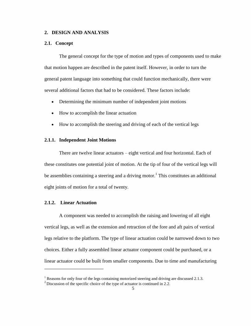
2.1.1. Independent Joint Motions
There are twelve linear actuators – eight vertical and four horizontal. Each of
these constitutes one potential joint of motion. At the tip of four of the vertical legs will
be assemblies containing a steering and a driving motor.1 This constitutes an additional
eight joints of motion for a total of twenty.
2.1.2. Linear Actuation
A component was needed to accomplish the raising and lowering of all eight
vertical legs, as well as the extension and retraction of the fore and aft pairs of vertical
legs relative to the platform. The type of linear actuation could be narrowed down to two
choices. Either a fully assembled linear actuator component could be purchased, or a
linear actuator could be built from smaller components. Due to time and manufacturing
1 Reasons for only four of the legs containing motorized steering and driving are discussed 2.1.3.
2 Discussion of the specific choice of the type of actuator is continued in 2.2.

6
constraints, the former option was chosen. In this way, the eight vertical legs in addition
to the four horizontal actuators would each be controlled by a linear actuator,
electronically controlled by the microprocessor unit.2
2.1.3. Steering and Driving
The choice of having four pairs of vertical legs with steering and driving motors is
not arbitrary. There are several possible configurations for which vertical legs have
steering and driving motors. Theoretically, the number configurations of steering and
driving motors could range all the way from all four pairs having steering and driving
motors to just one pair having them. In addition to the number of pairs of legs with
motors, any combination of configurations is also possible. For example, the front and
back vertical pairs could have driving and steering motors while the middle two pairs do
not. All of these considerations result in a large number of possible configurations, not all
of which are necessary to consider for the actual design. An approach was undertaken to
reduce the number of configurations that would need to be tested. The number and
configuration of pairs of legs with motors is determined by the required functionality of
the prototype. Since the prototype must accomplish regular driving on flat surfaces,
climbing over obstacles, and climbing up stairs, the pairs must be chosen in order to
satisfy each of these challenges.
In the case of regular driving on flat surfaces, the platform could be modeled like
a two-wheel drive car. Regular turning and driving can be accomplished with
2 Discussion of the specific choice of the type of actuator is continued in 2.2.
7
motors on just one pair of legs. Since this would mean that the other pair
contacting the ground would be free, the motorized pair would need to be in the
front if driving forward, and in the back if driving backwards. Caster wheels,
which are free in both driving and steering, could not lead the motion.
Climbing over obstacles would require at most motors on two pairs of legs. This
is because there is never an instance when there would be more than two pairs of
legs not touching the ground. Given all combinations of pairs that are contacting
or not contacting the ground at any given time, only two pairs of vertical legs
would need steering and driving motors.
Climbing up stairs is a more complicated process that implements all the available
joints of motion in the system. But even after analysis of each of the stages of
motion, at any given time at most only two pairs of legs would be utilizing their
steering and driving motors to move the device.3
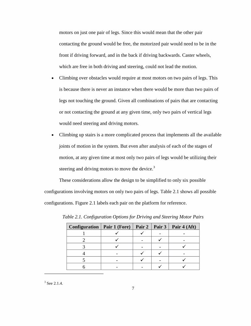
These considerations allow the design to be simplified to only six possible
configurations involving motors on only two pairs of legs. Table 2.1 shows all possible
configurations. Figure 2.1 labels each pair on the platform for reference.
Table 2.1. Configuration Options for Driving and Steering Motor Pairs
Configuration Pair 1 (Fore) Pair 2 Pair 3 Pair 4 (Aft)
1 - -
2 - -
3 - -
4 - -
5 - -
6 - -
3 See 2.1.4.
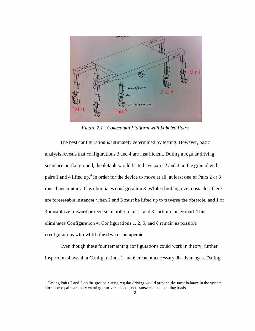
8
Figure 2.1 - Conceptual Platform with Labeled Pairs
The best configuration is ultimately determined by testing. However, basic
analysis reveals that configurations 3 and 4 are insufficient. During a regular driving
sequence on flat ground, the default would be to have pairs 2 and 3 on the ground with
pairs 1 and 4 lifted up.4 In order for the device to move at all, at least one of Pairs 2 or 3
must have motors. This eliminates configuration 3. While climbing over obstacles, there
are foreseeable instances when 2 and 3 must be lifted up to traverse the obstacle, and 1 or
4 must drive forward or reverse in order to put 2 and 3 back on the ground. This
eliminates Configuration 4. Configurations 1, 2, 5, and 6 remain as possible
configurations with which the device can operate.
Even though these four remaining configurations could work in theory, further
inspection shows that Configurations 1 and 6 create unnecessary disadvantages. During
4 Having Pairs 2 and 3 on the ground during regular driving would provide the most balance in the system,
since these pairs are only creating transverse loads, not transverse and bending loads.

9
the stair climbing sequence, there would be times where the two front pairs are on the
stairs and the two back pairs are on the ground. One of the front pairs and one of the back
pairs should have motorized wheels that can brake in place to keep the device from
slipping. Considering this as a safety precaution, Configurations 1 and 6 are not ideal.
This leaves Configurations 2 and 5 to test. Testing each of these remaining configurations
would ultimately determine which one is optimized for all conditions.5 In order to test
these two configurations, however, the legs would have to be designed so that the
components could be easily interchanged.
2.1.4. Moving Sequences
As previously mentioned, the three major applications of this device will be to 1)
travel on flat ground, 2) climb over obstacles, 3) climb up and down stairs. The most
frequent usage of the vehicle will be on flat ground, and this application is discussed first.
Climbing over obstacles and climbing up and down stairs are secondary applications that
will be discussed next.
The primary application of the device will be to travel on flat ground. When the
vehicle is travelling this way, there are two likely modes of operation. The first one has
Pairs 2 and 3 on the ground while Pairs 1 and 4 are raised. In order for this mode to be
feasible as a regular driving mode, a motorized pair would have to be put on Pair 2. This
configuration is named Mode 1. It is sketched in Figure 2.2.
5 See 3 for a determination of the final configuration.

10
Figure 2.2 - Regular Driving Mode 1
The second mode of operation has Pairs 1 and 4 on the ground while Pairs 2 and 3
are raised. This mode, Mode 2, is less common because during regular driving there is no
necessity for Pairs 1 and 4 to be controlling the motion and therefore inducing
unnecessary bending in their horizontal actuators.6 Mode 2 is shown in Figure 2.3.
Figure 2.3 - Regular Driving Mode 2
The next major application of the device is to traverse obstacles. A brief sequence
is laid out in this section to demonstrate how this will be accomplished. Stage 1 involves
extending Pair 1 over the obstacle, while keeping the rest of the pairs in place. Figure 2.4
shows Stage 1.7
6 Even if the horizontal actuators are completely retracted, the fact that Pairs 1 and 4 are farther away than
Pairs 2 and 3 from the center of gravity means that there will be additional stress on the platform. If this can
be avoided, it should be. 7 All arrows in Figures 2.3 – 2.18 indicate the direction of motion that took place in order for the joint to
arrive at that position. For example, an up arrow on a vertical actuator means that the actuator retracted to

11
Figure 2.4 - Obstacle Climbing Sequence Stage 1
Once Pair 1 is extended over the obstacle, Pairs 1 and 4 must be lowered to the
ground so that Pairs 2 and 3 can traverse the space over the obstacle. Stage 2 is shown in
Figure 2.5.
Figure 2.5 - Obstacle Climbing Sequence Stage 2
Stage 3 involves carrying the platform over the obstacle. This can most easily be
accomplished by rolling Pairs 1 and 4 forward as far as possible. If necessary, depending
upon the size of the obstacle, extension of the horizontal actuators might be required for
extra distance. Stage 3 is shown in Figure 2.6.
get to that position. It does not indicate the motion of the next stage. Labels such as “P1” refer to the pair of
actuators, such as “Pair 1,” being discussed in the text.

12
Figure 2.6 - Obstacle Climbing Sequence Stage 3a
Figure 2.6 shows that in order for the platform to completely traverse the obstacle,
Pair 4’s horizontal actuators must extend past the obstacle. Figure 2.7 demonstrates what
is, in this case, a necessary second part to Stage 3.
Figure 2.7 - Obstacle Climbing Sequence Stage 3b
In order to complete the sequence, Pairs 2 and 3 must lower to the ground and
Pairs 1 and 4 must return to their original raised position. Figure 2.8 shows Stage 4, the
final stage. After Stage 4, the device will begin driving on flat ground again.
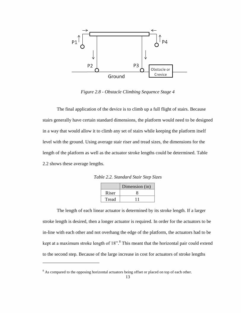
13
Figure 2.8 - Obstacle Climbing Sequence Stage 4
The final application of the device is to climb up a full flight of stairs. Because
stairs generally have certain standard dimensions, the platform would need to be designed
in a way that would allow it to climb any set of stairs while keeping the platform itself
level with the ground. Using average stair riser and tread sizes, the dimensions for the
length of the platform as well as the actuator stroke lengths could be determined. Table
2.2 shows these average lengths.
Table 2.2. Standard Stair Step Sizes
Dimension (in)
Riser 8
Tread 11
The length of each linear actuator is determined by its stroke length. If a larger
stroke length is desired, then a longer actuator is required. In order for the actuators to be
in-line with each other and not overhang the edge of the platform, the actuators had to be
kept at a maximum stroke length of 18”.8 This meant that the horizontal pair could extend
to the second step. Because of the large increase in cost for actuators of stroke lengths
8 As compared to the opposing horizontal actuators being offset or placed on top of each other.
14
over 30”, it was decided early on that the prototype would be demonstrated using a
specially fabricated staircase with the same length tread but half-scaled risers. As will be
described in the following diagrams, this riser height of 4” would allow the maximum
height dimension (28”) to be reached with a 30” stroke linear actuator.
Analysis of each stage of the motion of the device up a flight of stairs was the key
to determining certain dimensions. Figure 2.10 through Figure 2.20 describe the eleven
stage process involved in the device travelling from flat ground to being completely on a
set of stairs.
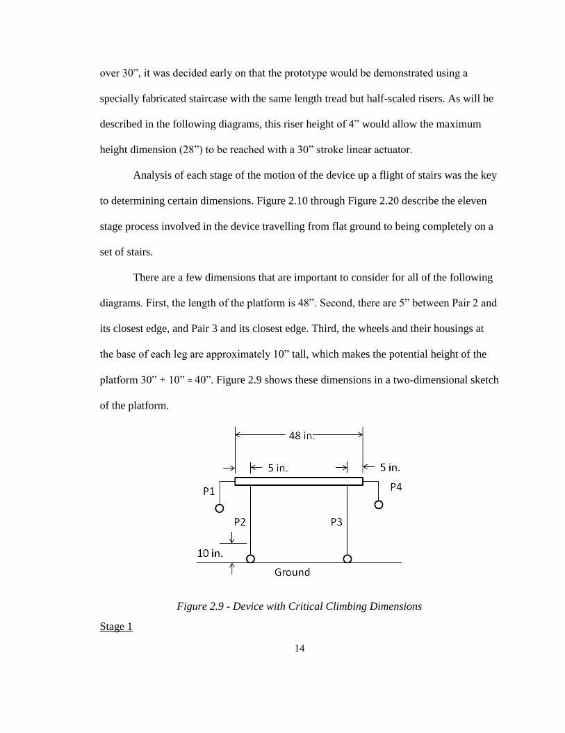
There are a few dimensions that are important to consider for all of the following
diagrams. First, the length of the platform is 48”. Second, there are 5” between Pair 2 and
its closest edge, and Pair 3 and its closest edge. Third, the wheels and their housings at
the base of each leg are approximately 10” tall, which makes the potential height of the
platform 30” + 10” ≈ 40”. Figure 2.9 shows these dimensions in a two-dimensional sketch
of the platform.
Figure 2.9 - Device with Critical Climbing Dimensions
Stage 1

15
Figure 2.10 - Stage 1 of Climbing Sequence
The first stage of motion involves moving Pair 1 from the ground to the second
stair.9 This involves retracting Pair 1’s vertical actuators and extending its horizontal
ones. The maximum distance between Pair 1 and Pair 2 is 23”; 18” of stroke plus 5” from
Pair 2 to the edge of the platform where the stroke begins. To position Pair 1 at the center
of stair 2, the actuator must extend a minimum of 13.5”.10
Stage 2
Figure 2.11 - Stage 2 of Climbing Sequence
9 The first ten diagrams show Pair 4 touching the ground. While this is not necessary until Stage 8, it is
shown simply for consistency. Lowering Pair 4 in preparation for a stair climbing sequence would also save
time, since Pair 4 must contact the ground during the sequence. 10
This minimum distance assumes the wheels of Pair 2 are touching the base of the first step. The distance
between the edge of the wheels on Pair 2 and the edge of the platform is 3”. This is overhang over the first
step, so by subtracting this from one and a half times the tread length (16.5”) gives 13.5”.
16
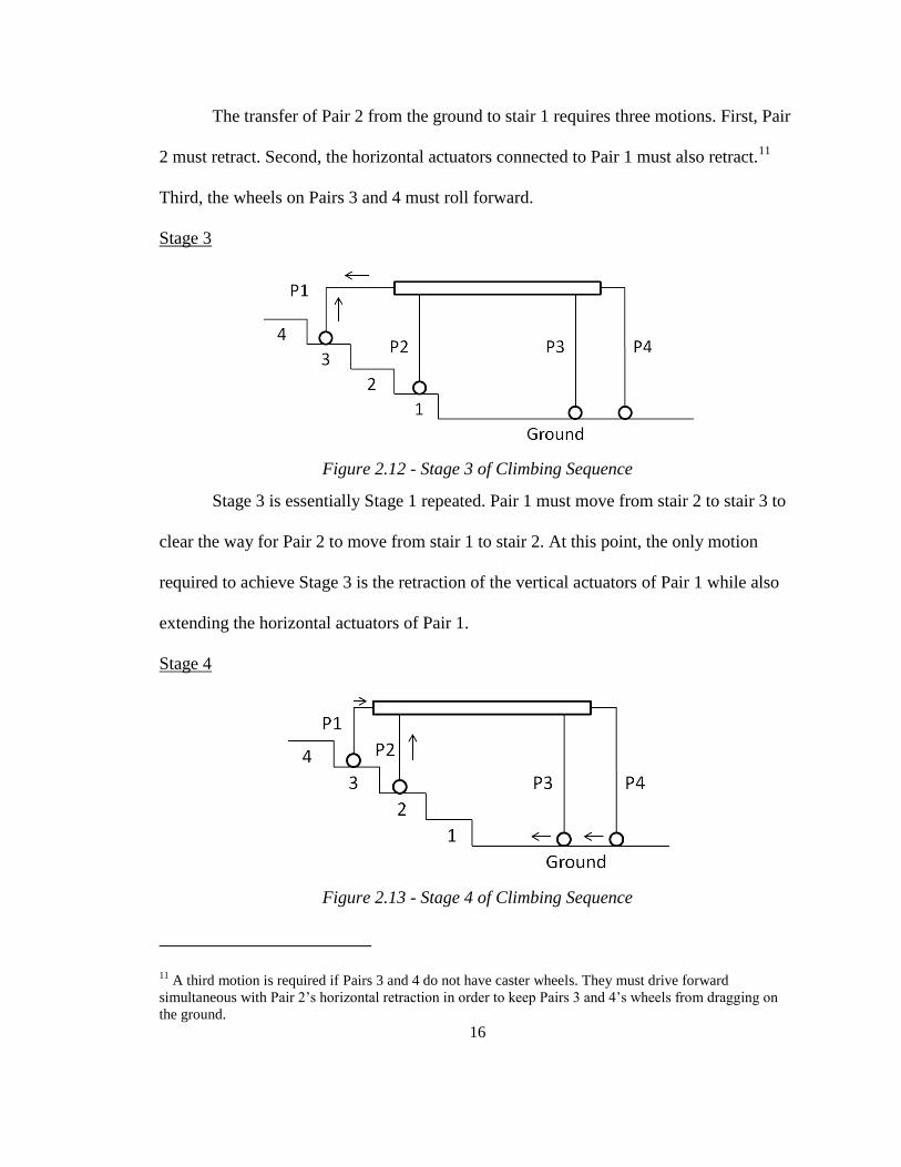
The transfer of Pair 2 from the ground to stair 1 requires three motions. First, Pair
2 must retract. Second, the horizontal actuators connected to Pair 1 must also retract.11
Third, the wheels on Pairs 3 and 4 must roll forward.
Stage 3
Figure 2.12 - Stage 3 of Climbing Sequence
Stage 3 is essentially Stage 1 repeated. Pair 1 must move from stair 2 to stair 3 to
clear the way for Pair 2 to move from stair 1 to stair 2. At this point, the only motion
required to achieve Stage 3 is the retraction of the vertical actuators of Pair 1 while also
extending the horizontal actuators of Pair 1.
Stage 4
Figure 2.13 - Stage 4 of Climbing Sequence
11 A third motion is required if Pairs 3 and 4 do not have caster wheels. They must drive forward
simultaneous with Pair 2’s horizontal retraction in order to keep Pairs 3 and 4’s wheels from dragging on
the ground.
17
Stage 4 is closely related to Stage 2. Pair 2 must move from stair 1 to stair 2. This
is accomplished by the retraction of Pair 2 and the retraction of Pair 1’s horizontal
actuators.12
The wheels on Pairs 3 and 4 will bring the backside of the platform forward.
Stage 5
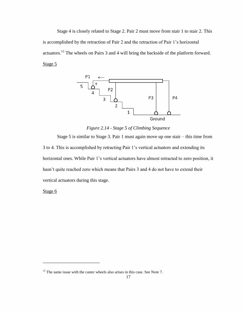
Figure 2.14 - Stage 5 of Climbing Sequence
Stage 5 is similar to Stage 3. Pair 1 must again move up one stair – this time from
3 to 4. This is accomplished by retracting Pair 1’s vertical actuators and extending its
horizontal ones. While Pair 1’s vertical actuators have almost retracted to zero position, it
hasn’t quite reached zero which means that Pairs 3 and 4 do not have to extend their
vertical actuators during this stage.
Stage 6
12 The same issue with the caster wheels also arises in this case. See Note 7.
18
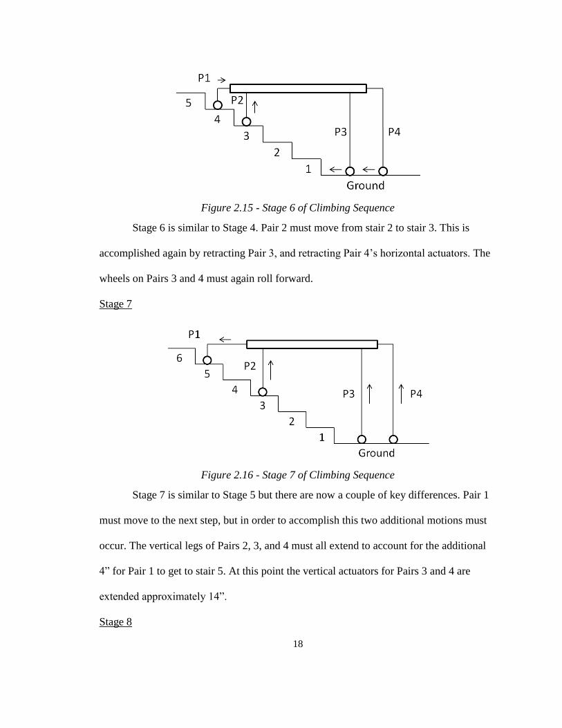
Figure 2.15 - Stage 6 of Climbing Sequence
Stage 6 is similar to Stage 4. Pair 2 must move from stair 2 to stair 3. This is
accomplished again by retracting Pair 3, and retracting Pair 4’s horizontal actuators. The
wheels on Pairs 3 and 4 must again roll forward.
Stage 7
Figure 2.16 - Stage 7 of Climbing Sequence
Stage 7 is similar to Stage 5 but there are now a couple of key differences. Pair 1
must move to the next step, but in order to accomplish this two additional motions must
occur. The vertical legs of Pairs 2, 3, and 4 must all extend to account for the additional
4” for Pair 1 to get to stair 5. At this point the vertical actuators for Pairs 3 and 4 are
extended approximately 14”.
Stage 8
19
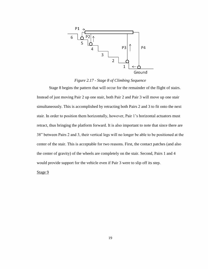
Figure 2.17 - Stage 8 of Climbing Sequence
Stage 8 begins the pattern that will occur for the remainder of the flight of stairs.
Instead of just moving Pair 2 up one stair, both Pair 2 and Pair 3 will move up one stair
simultaneously. This is accomplished by retracting both Pairs 2 and 3 to fit onto the next
stair. In order to position them horizontally, however, Pair 1’s horizontal actuators must
retract, thus bringing the platform forward. It is also important to note that since there are
38” between Pairs 2 and 3, their vertical legs will no longer be able to be positioned at the
center of the stair. This is acceptable for two reasons. First, the contact patches (and also
the center of gravity) of the wheels are completely on the stair. Second, Pairs 1 and 4
would provide support for the vehicle even if Pair 3 were to slip off its step.
Stage 9

20
Figure 2.18 - Stage 9 of Climbing Sequence
Stage 9 is almost identical to Stage 7. Pair 1 must move its leg up one stair. But
again Pairs 2, 3 and 4 must extend their vertical actuators to account for this additional 4”
by Pair 1 moving up a stair.
Stage 10
Figure 2.19 - Stage 10 of Climbing Sequence
Stage 10 is similar to Stage 8. Both Pairs 2 and 3 will move up 1 step
simultaneously. This is achieved by Pairs 2 and 3 retracting 4” while Pair 1 retracts its
horizontal actuator to move the platform forward. Pair 4’s horizontal actuators will likely
have to extend slightly at this point. Pair 4 has reached ymax = 28”. At every even stage
from this point forward, Pair 4 must extend to ymax.

21
Stage 11
Figure 2.20 - Stage 11 of Climbing Sequence
Stage 11 now combines the motion of both Pairs 1 and 4. This can be
accomplished because the platform is now fully on the stairs, making its pattern of
motion repeatable every 2 stages. Pair 2 and 3 will extend, while Pair 4’s horizontal
actuators retract to put it on the new stair. Simultaneously Pair 1 will extend its horizontal
actuators to place it on the 7th
stair.
Now that the platform is entirely on the stairs, Stages 10 and 11 will be repeated
until the platform reaches the top of the stairs. At this point, Pairs 3 and 4 will do the
inverse of what Pairs 1 and 2 did for the first several stages. With Pairs 1 and 2 on the top
of the staircase, Pairs 3 and 4 must simply alternate one stair at a time until they have also
reached the top.

22
In summary, each stage requires specific joints to move to locate the device at the
correct position. Table 2.3 illustrates the results of each stage.
Table 2.3. Summary of Stair Climbing Sequence
Stage Pair 1 Pair 2 Pair 3 Pair 4
1 Stair 2 Ground Ground Ground
2 Stair 2 Stair 1 Ground Ground
3 Stair 3 Stair 1 Ground Ground
4 Stair 3 Stair 2 Ground Ground
5 Stair 4 Stair 2 Ground Ground
6 Stair 4 Stair 3 Ground Ground
7 Stair 5 Stair 3 Ground Ground
8 Stair 5 Stair 4 Stair 1 Ground
9 Stair 6 Stair 4 Stair 1 Ground
10 Stair 6 Stair 5 Stair 2 Ground
11 Stair 7 Stair 5 Stair 2 Stair 1
In order to travel down a flight of stairs, the sequence must simply do the reverse
of what it did to climb up the stairs. This time, instead of Pair 1 retracting its vertical
actuators and extending its horizontal ones, it will extend its vertical actuators and extend
its horizontal ones. The device can then sequentially lower Pair 2 to reach the top step,
just as Pair 2 was raised to reach the first step in the ascension sequence. The pattern
continues until the platform has reached the bottom of the stairs.
2.2. Mechanical Design
There were four stages involved in the mechanical design of the device. First, the
conceptual design had to be broken down into parts and assemblies that could accomplish
the required functionality. Second, analysis was conducted to prove that each of these
designed parts would be feasible and operate correctly. Third, components were selected

23
based on the analysis. Fourth, a solid model was constructed which could be used to
create drawings for the manufacturing phase.
2.2.1. Configuration Options
The device can be broken down into two main categories: the vertical legs and the
frame. There are two different versions of the vertical legs – one with drive and steering
motors and the other without either. The more complex version contains the drive and
steering motors, and therefore required the most careful analysis and consideration. The
complex vertical leg had to accomplish two goals: 1) rotate the base of the leg assembly
relative to the actuator tip, and 2) rotate the wheel in contact with the ground.
1) The rotation of the leg base could be accomplished by installing a bearing.
The two types of bearings that were considered were turntable bearings (e.g. a
lazy susan bearing) and banded ball thrust bearings. Choosing a ball bearing
would have increased the complexity of the design without adding any
comparative benefits. The bearing needed to survive a thrust load, because the
leg itself would not always be in contact with the ground. Without the band to
keep the inner race and outer race from separating, a regular ball bearing
would have fallen apart the moment the leg lifted off the ground. Figure 2.21
shows a section view of the standard ball thrust bearing, which demonstrates
the lack of feasibility without the band. Figure 2.22 shows a generic banded
ball thrust bearing.
24
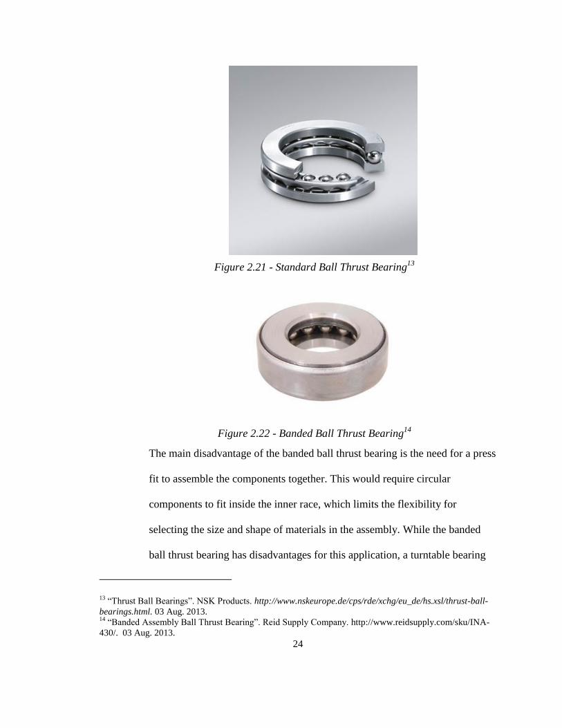
Figure 2.21 - Standard Ball Thrust Bearing13
Figure 2.22 - Banded Ball Thrust Bearing14
The main disadvantage of the banded ball thrust bearing is the need for a press
fit to assemble the components together. This would require circular
components to fit inside the inner race, which limits the flexibility for
selecting the size and shape of materials in the assembly. While the banded
ball thrust bearing has disadvantages for this application, a turntable bearing
13 “Thrust Ball Bearings”. NSK Products. http://www.nskeurope.de/cps/rde/xchg/eu_de/hs.xsl/thrust-ball-
bearings.html. 03 Aug. 2013. 14
“Banded Assembly Ball Thrust Bearing”. Reid Supply Company. http://www.reidsupply.com/sku/INA-
430/. 03 Aug. 2013.

25
could survive in both tension and compression and has the advantage of being
low cost. Another key advantage of the turntable bearing is that it has
convenient locations for attaching the other parts of the assembly. Ultimately,
the turntable bearing was chosen because it could handle the loading
conditions of the leg, was low cost, and could be easily integrated into the
assembly. Figure 2.23 shows how the turntable bearing operates within the
assembly.
Figure 2.23 - Turntable Bearing with Assembly
2) The rotation of the wheel could be accomplished by either using a direct
connection between the motor shaft and the wheel, or through a power train.
Each has a key disadvantage at the outset. Direct attachment requires that the
motor spin speed and torque are the correct amount without being able to
adjust with a gear reduction or some other power train method. The power
train option is more complex and thus requires more components. Because

26
cost was a consideration for every aspect of the design and manufacturing, a
solution had to be found that could allow for the selection of low cost motors.
Eventually cost drove the decision for the direct attachment method.15
The selection of direct attachment for the drive mechanism requires a bracket to
attach the motor to the rest of the leg base. This could be accomplished with a U-shaped
metal bracket with the motor attached on one side and the leg attached on the other. With
direct attachment, care had to be taken to ensure that the motor shaft and wheel shaft
were correctly aligned. Ensuring alignment via manual machining methods only would
be very difficult, so the decision was made to install a flex-coupling between the two
shafts. This would eliminate the negative effects of any small amount of parallel
misalignment between the two shafts. Figure 2.24 shows the motor, U-bracket, wheel
shaft, and flex coupling portion of the assembly.
15 See 2.2.3.

27
Figure 2.24 - Flex Coupling Connection
The wheel shaft was attached to bearings on each end. Banded ball thrust bearings
were selected because, during operation, the shaft could experience forces parallel to the
axis of rotation. As discussed before, a regular ball bearing cannot protect against a thrust
load. These bearings were installed inside their own pillow blocks, which were fastened
to a wheel housing. The wheel housing needed to be shaped in such a way as to allow the
wheel to fit inside while simultaneously allowing for easy fastening to each of the pillow
blocks, as well as the rest of the assembly above it. Figure 2.25 shows how the selection
of square tubing made sense to meet these requirements.
28
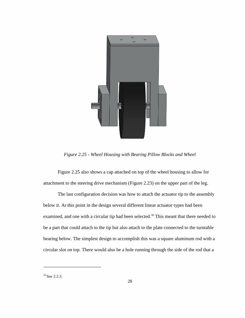
Figure 2.25 - Wheel Housing with Bearing Pillow Blocks and Wheel
Figure 2.25 also shows a cap attached on top of the wheel housing to allow for
attachment to the steering drive mechanism (Figure 2.23) on the upper part of the leg.
The last configuration decision was how to attach the actuator tip to the assembly
below it. At this point in the design several different linear actuator types had been
examined, and one with a circular tip had been selected.16 This meant that there needed to
be a part that could attach to the tip but also attach to the plate connected to the turntable
bearing below. The simplest design to accomplish this was a square aluminum rod with a
circular slot on top. There would also be a hole running through the side of the rod that a
16 See 2.2.3.

29
bolt could fit through. The actuator tip came with a 12 mm hole to allow for this sort of
fastening. Figure 2.26 shows how the actuator tip is integrated with the leg base.
Figure 2.26 - Actuator Tip Being Inserted Into Block to Complete Assembly
If the tube inside the actuator does not rotate, then the steering motor would stay
in place as it caused the pulley to rotate the drive mechanism below it. In this way, the
only rotating components would be everything below the steering motor mounting plate.
2.2.2. Analysis
Engineering analysis was conducted for components that were directly related to
certain specifications or needed to meet some threshold in order for the device to
function. The mechanical design analysis includes:
1) Drive motor torque
2) Deflection of drive bracket

30
3) Deflection of wheel shaft
4) Tension and reduction of timing belt
5) Steer motor torque
6) Deflection of steering plate
7) Horizontal support shaft deflection
8) Allowable torque of wheel shaft press fit
9) Tension in linear actuator mounting screws
10) Bending stress and deflection of platform
While all of these calculations are included in Appendix B, there were several
considerations and assumptions in the calculations that require discussion. All of the
equations discussed in this section were taken from Shigley’s Mechanical Engineering
Design, 9th
Edition [3] unless otherwise specified.
1) The torque requirements for the drive motor were based on known equations for
ground vehicle dynamics [3]. The analysis was conducted by taking the variable
inputs and placing them sequentially into six key equations. These equations are
as follows:

31
Table 2.4 shows each variable involved in the calculations and its
corresponding value for this application.
Table 2.4. Variable Inputs for Driving Torque Calculations
Input Symbol Value
Gross Vehicle Weight GVW 240 lb
Weight on each drive wheel Wd 60 lb
Radius of wheel R 2 in
Desired top speed Vmax 1.76 ft/s (1.2 mph)
Desired acceleration time atime 2 sec.
Max incline angle α 0
Resistance factor RF 1.15
Frictional coefficient μ 0.4 (rubber and concrete)
Worst working surface f 0.015 (concrete, fair)
The gross vehicle weight was determined by making a rough weight
estimate for each component. The weight on each drive wheel is simply the total
weight divided by four, since there will be at least four wheels in contact with the
ground at all times. The radius of the wheel was chosen to be 2” because the
bottom of the drive motor would have come in contact with the ground had a
radius of 1.5” been chosen. 2” is the next standard wheel size that gives adequate
space. The estimated vehicle speed of 3mph was initially chosen based on a
reasonable estimate of an average person walking. It was later reduced to 1.2 mph
for the speed output of the drive motors that were selected. Although future designs
will potentially want to consider making the device faster, the prototype was concerned
only with getting a minimal amount of motion to prove functionality. The desired
acceleration time was selected to accelerate to 1.2 mph from a standstill in 2

32
seconds.17
The max incline angle was assumed to be zero since the demonstration
of the prototype will only occur on flat ground (or in the case of stairs, motion
parallel to the flat ground). Most of the time this device will be travelling on
concrete, so an intermediate value of “fair” was chosen. The value of “fair” falls
between “poor” and “good,” which are both measurements of the quality of the
traction on the concrete. “Fair” corresponds to a numerical value of 0.015, where
all values of concrete typically range between 0.01 and 0.02 [2]. The final
equation, which calculates the maximum tractive torque (MTT), was used as a
check to ensure that the wheel would not slip on the ground’s surface during
operation. If it could be shown that value of MTT is greater than the value of the
drive torque for one wheel (Tw), then the wheels would not slip. MTT was
calculated to be 48 in-lb, while the drive torque was calculated to be 26.1 in-lb.
Therefore, the wheels would not slip during operation.
2) The deflection in the drive motor mounting bracket was critical in determining the
thickness of material in the bracket required in order to keep the motor from
contacting the ground. The portion of the bracket parallel to the ground was
modeled as a cantilever beam with an end load and end moment. The end load is
simply the weight of the motor, while the end moment is caused by the fact that
the center of gravity of the motor is not in line with the end of the bracket. Figure
2.27 shows a diagram of the system.
17 The acceleration time was discovered to be much less during testing. This was because the motors spun
up to full speed without any motion control. Some reasonable estimate still had to be given for the sake of
the torque calculations, however.

33
Figure 2.27 - Diagram of Driving Motor Bracket Analysis
There were three key equations used to calculate the deflection. They are
shown as follows:
The first equation calculates the deflection at the tip of the bracket due to the
moment caused by the weight of the motor. The second equation calculates the deflection
due to the weight of the motor itself. These are summed up in the final equation to give
the total deflection caused by the driving motor.
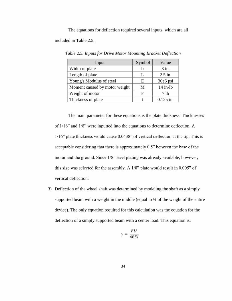
34
The equations for deflection required several inputs, which are all
included in Table 2.5.
Table 2.5. Inputs for Drive Motor Mounting Bracket Deflection
Input Symbol Value
Width of plate b 3 in.
Length of plate L 2.5 in.
Young's Modulus of steel E 30e6 psi
Moment caused by motor weight M 14 in-lb
Weight of motor F 7 lb
Thickness of plate t 0.125 in.
The main parameter for these equations is the plate thickness. Thicknesses
of 1/16” and 1/8” were inputted into the equations to determine deflection. A
1/16” plate thickness would cause 0.0438” of vertical deflection at the tip. This is
acceptable considering that there is approximately 0.5” between the base of the
motor and the ground. Since 1/8” steel plating was already available, however,
this size was selected for the assembly. A 1/8” plate would result in 0.005” of
vertical deflection.
3) Deflection of the wheel shaft was determined by modeling the shaft as a simply
supported beam with a weight in the middle (equal to ¼ of the weight of the entire
device). The only equation required for this calculation was the equation for the
deflection of a simply supported beam with a center load. This equation is:
35
The inputs for this equation are listed in Table 2.6.
Table 2.6. Inputs for Deflection of Wheel Shaft
Input Symbol Value
Diameter of wheel shaft d 0.375 in.
Length of shaft between supports (bearings) L 4 in.
Young's Modulus of steel E 10.4e6 psi
Weight on each wheel F 60 lb
With a minimum18
shaft thickness of 0.375”, the resulting deflection was
0.008”. This is essentially negligible and would not result in contact between the
wheel and its housing.
4) The effective tension and desired pulley reduction would determine the correct
pulley and timing belt sizes. In order to determine these values, five equations had
to be used. These equations calculate the pitch diameters of each pulley, the
length of the timing belt, the torque seen by the motor after the pulley reduction,
and lastly the effective tension itself. These five equations are as follows [4]:
18 The shaft was stepped to account for the difference between the wheel’s hole and the bore diameter of
the bearings. The smaller of the two diameters was selected for calculations.

36
The required inputs for these equations are shown in Table 2.7.
Table 2.7. Inputs for Tension and Reduction of Timing Belt
Input Symbol Value
Center distance C 3.5 in.
L-series timing belt pitch p 0.375 in.
Number of teeth of driving pulley zp1 10
Number of teeth of driven pulley zp2 22
Belt width b 0.5 in.
Max required torque to steer Tmax 25.5 in-lb
Pulley ratio n 2.2
Max allowable tension for L-series belt T1all 100 in-lb
Using the center to center distance and calculated pitch diameters, the
required belt length was determined to be 13.0”. Using the driving torque, number
of teeth, and pulley geometry, the effective tension of the system was calculated
to be 19.4 lb. [4]. The maximum allowable tension in an L-series timing belt is
100 lb, so the selection of a 130L05019
timing belt was adequate. Slots were
included in the steering motor mounting bracket to allow for belt tensioning.
5) The required steering motor torque was determined by estimating the contact
patch radius and using it as the moment arm to determine the frictional torque. If
the applied torque from the motor could be shown to be greater than the frictional
torque, then steering would be successful. A few key assumptions were made for
these calculations. First, a test was done to determine the size and shape of the
contact patch. An epoxy patch was painted onto a section of the bottom wheel.
19 The first three digits “130” represent length to one decimal place. “L” stands for L-series. “050” stands
for 0.5” belt width. The pitch of this L-series belt is 0.375”.

37
The bottom of the wheel was pressed down against a piece of paper and then
lifted up. This was done several times to get a consistent contact patch size. The
assumption made here was that the contact patch was a circle, which doesn’t
diverge much from the actual epoxy mark itself.20
Figure 2.28 shows one of the
contact patch marks.
Figure 2.28 - Contact Patch of Drive Wheel
Second, the steering conditions assume that the vehicle is not also driving.
While this assumption will produce a larger amount of torque to overcome the
friction (since the required steering torque is less when the vehicle is in motion),
this assumption will produce the worst-case torque that the motor must surpass.
Third, the coefficient of friction between hard rubber and cement in dry
conditions is 0.85 [5].
20 In the event that the contact patch is not circular, one could calculate an average radius and use that for
the frictional torque equations.

38
There were two main equations used to calculate the steering torque. The
first equation is:
This equation gives the frictional force between the wheel and the ground. The
second equation calculates the frictional torque.
As shown in the second equation, the frictional torque is found by multiplying the
radius of the contact patch by the frictional force between the ground and the
wheel. The inputs needed for these equations are listed in Table 2.8.
Table 2.8. Inputs for Steering Motor Torque
Input Symbol Value
Coefficient of friction between dry concrete and hard rubber μ 0.85
Weight on each wheel w 60 lb
Radius of contact patch r 0.5 in.
The largest frictional torque for a wheel to overcome on cement was
determined to be 25.5 in-lb. A steering motor and gear reduction with at least this
much continuous torque would be required for full functionality.
6) The deflection of the steering motor mounting plate is critical because too much
bending would result in the edge with the steering motor to contact the top of the
drive motor. The system was modeled as a cantilever beam (the mounting plate)
with an end load (the motor), since worst case deflection would be seen at the
very tip of the mounting plate. The equation for the deflection of a cantilever
beam with an end load is:

39
The inputs required for this calculation are included in Table 2.9.
Table 2.9. Inputs for Deflection of Steering Motor Mounting Plate
Input Symbol Value
Weight of steering motor F 8 lb
Cantilever length L 4 in.
Young's Modulus of steel E 30e6 psi
Width of plate b 3 in.
Height (thickness) of plate h 0.125 in.
The results indicate that there will be at most 0.012” of deflection. This is
acceptable as it does not exceed the maximum allowable deflection of 0.88”,
which is based on the spacing between the plate and the drive motor.
7) The deflection of the horizontal support shaft (one in parallel with each horizontal
actuator) is important to determine the angle at which Pair 1 and Pair 4’s vertical
actuators contact the ground. The deflection was calculated in two stages. First,
each shaft was modeled as a cantilever beam with an end load equivalent to ¼ the
weight of the platform. The length of the beam is the maximum stroke length of
the horizontal actuators (18”). The deflection at the tip is the portion of the
deflection only due to the bending in the aluminum rods. In order to acquire the
actual deflection of the tip, the deflection and angle at the edge of the platform
would have to be added. There were four key equations necessary to calculate the
deflection and angle due to both the aluminum and the platform itself. These
equations are:

40
The inputs required to calculate the deflections and angles are shown in
Table 2.10.
Table 2.10. Inputs for Horizontal Support Shaft Deflection
Input Symbol Value
Force seen by each shaft F 60 lb
Moment arm of horizontal extension a 18 in.
Center distance between linear bearings L 6.88 in.
Total length of platform Lp 48 in.
Young's Modulus of aluminum E 10.4e6 psi
Young's Modulus of platform (plywood) Ep 1.01e6 psi
Outer diameter of support shaft do 1 in.
Inner diameter of support shaft di 0.5 in.
The total deflection, acquired by adding ya and yp together, comes out to
be 0.346”. This means that the vertical legs will be contacting the ground at an
angle equal to the sum of θa and θp, or 1.2°.
8) The torque allowed by the wheel shaft press fit was determined by calculating the
minimum interference fit such that the hard rubber wheel and solid aluminum
shaft would not slip relative to each other. The inner diameter of the hard rubber
wheel was known to be 0.404 in., and the diameter of the aluminum shaft could

41
be sized to allow for sufficient diametral interference. The allowable torque needs
to exceed the drive torque of 26.1 in-lb. Two equations, one for the pressure in the
fit and one for the allowable torque, were used. These are:
The inputs required for these two equations are shown in Table 2.11.
Table 2.11. Inputs for Wheel Shaft Press Fit
Input Symbol Value
Nominal diameter of wheel shaft d 0.401 in.
Outside diameter of wheel do 4 in.
Inside diameter of shaft di 0
Poisson’s Ratio for aluminum vi 0.333
Poisson’s Ratio for hard rubber vo 0.5
Young's Modulus for hard rubber Eo 14.5e3 psi
Young's Modulus for aluminum Ei 10.4e6 psi
Coefficient of friction between aluminum and hard rubber f 1
Length of interference fit L 1.6 in.
Minimum required torque21
Tall 25.5 in-lb
A minimum diametral interference fit of 0.00265” was calculated based on
these parameters. A diametral interference fit of 0.003” was chosen for ease of
machining.
21 The torque was known from previous calculations. Simultaneously solving both equations would give
solutions for p and δ.

42
9) The vertical actuators would have to be mounted to the vertical connector blocks
using the three screw holes near the tip. The tensile force that these screws would
see is equal to ¼ the weight of the platform minus the weight of each wheel
assembly. In order to include a safety factor, the tensile force was assumed to be
¼ of the weight of the device without subtracting the wheel assembly weight. The
allowable tensile stress in each screw (made of 18-8 stainless steel) is 42.1 ksi.
This means that each screw could not handle more tensile stress than this without
permanent set. Using basic equations to the calculate tensile stress in the bolts, an
acceptable bolt size could be determined. The two equations calculated the tensile
stress area as well as the tensile (axial) stress per bolt. These equations are:
The inputs required to perform these calculations are included in Table
2.12.
Table 2.12. Inputs for Actuator Mounting Screw Stress
Input Symbol Value
Max force applied on each leg F 60 lb
Minor diameter of #4-40 machine screw d 0.106 in.
Number of screws Ns 3
Based on the calculations each screw would only see 2.27 ksi, which falls
far below the maximum.

43
10) The bending stress of the platform was determined by treating the platform as a
simply supported beam with a center load (mostly due to the battery and weight of
the platform itself). With these conditions, the maximum bending moment occurs
at the center of the platform. The moment of inertia was determined by the section
properties of the solid model. The only required equations were those for the
maximum bending moment in a simply supported beam with a center load, as
well as the bending stress given that maximum bending moment. These equations
are:
The inputs required to perform these calculations are included in Table
2.13.
Table 2.13. Inputs for Bending Stress in Platform
Input
Symbol Value
Maximum stroke length of horizontal actuators h 18 in.
Weight load seen by platform w 240 lb
Length of platform Lp 48 in.
Area moment of inertia of platform Ip 46.125 in.4
Distance to neutral axis c 2 in.
With these numbers the maximum bending stress was calculated to be 219
psi. For plywood, bending stress should not exceed 1668 psi. Therefore, with the

44
plywood and 2x4 assembly, the wooden platform would suffice to take all of the
loads.
2.2.3. Component Selection
Most of the components in the design for both the vertical legs and frame were
machined. There were some, however, that had to be purchased directly. The following is
a list of the mechanical components that were purchased. All of these parts are also listed
in the bill of materials in Appendix C.
1) Driving motors
2) Steering motors
3) Timing belt pulley assemblies
4) Banded ball thrust bearings for wheel shaft
5) Flex couplings
6) Turntable bearings
7) Linear actuators (30” and 18” strokes)
8) Linear bearings
All of these components had at least one driving factor behind their purchase.
While meeting the specifications of the analysis was the most important factor for all the
components, cost ended up being a significant factor in several decision.
1) The biggest challenge in the selection of the motors for both driving and steering
was minimizing cost. Detailed research was conducted into several different
manufacturers and distributors of new brushed DC motors, and all of the ones that
met the requirements were prohibitively expensive. Because of this cost issue,

45
research was conducted on used motors. Eventually, feasible solutions for both
the driving and steering motors were found. In the case of the drive motor, a right-
angle gear motor was found that ran at 12V, drawing no more than 8A under a
loading output of 26 in-lb. The right-angle configuration simplified the design by
not requiring a worm gear or flexible shaft setup to account for the 90 degree
angle between the motor (mounted parallel to the leg) and the wheel shaft
(mounted perpendicular to the leg). Figure 2.29 shows the right angle drive motor.
Figure 2.29 - Right Angle Geared Motor for Driving22
This specific motor also runs at 100 RPM under design loading conditions. This
translates to 1.2 mph with a 4” diameter wheel. The cost of this motor was only
$60, as compared to costs of no less than $200 for new motors with similar
specifications.
2) The selection of the steering motor followed a very similar process as the driving
22 100 RPM 12 VDC Gearmotor. Surplus Center. http://www.surpluscenter.com/item.asp?item=5-
1649&catname=electric. 05 Aug. 2013.
46
motor. A motor with at least 12.75 in-lb of torque (which would become the
required 25.5 in-lb. with the 2:1 pulley ratio) was needed to overcome the contact
patch friction. The same distributor which sold the driving motors also sold inline
DC gear motors for only $50 that met the specifications. Figure 2.30 shows the
inline type that was purchased.
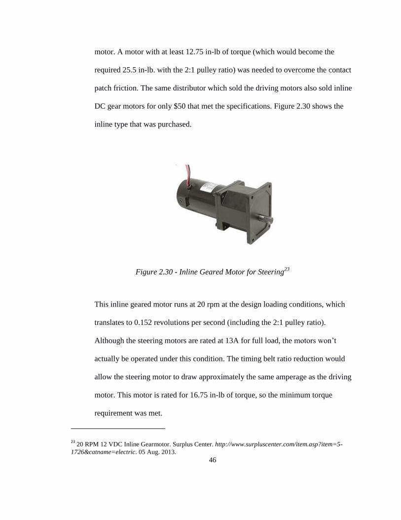
Figure 2.30 - Inline Geared Motor for Steering23
This inline geared motor runs at 20 rpm at the design loading conditions, which
translates to 0.152 revolutions per second (including the 2:1 pulley ratio).
Although the steering motors are rated at 13A for full load, the motors won’t
actually be operated under this condition. The timing belt ratio reduction would
allow the steering motor to draw approximately the same amperage as the driving
motor. This motor is rated for 16.75 in-lb of torque, so the minimum torque
requirement was met.
23 20 RPM 12 VDC Inline Gearmotor. Surplus Center. http://www.surpluscenter.com/item.asp?item=5-
1726&catname=electric. 05 Aug. 2013.

47
3) The main factors behind the choice of a timing belt to steer the leg were the
allowable tension and the spacing. The allowable tension of an L-series timing
belt with ½” width and 3/8” pitch is 100 lb. The calculated 19.4 lb transmitted
under this applications loading condition falls far below the maximum. Originally,
gears were going to be used to solve the problem of connecting the mechanical
source (the motor shaft) to the leg. The distance between the motor shaft and the
edge of the motor's gearbox, in addition to the short length of the shaft itself,
made gears an impractical solution. Instead of trying to cram the motor as close to
the leg as possible, an alternative approach was taken. By using a timing belt, any
length could be chosen to allow the motor to be situated in such a way as to not
interfere with the rotation of the leg.
4) As previously discussed, the choice of banded ball thrust bearings was related to
the potential thrust load on the wheels. It wasn’t necessary to consider other
bearings mainly due to cost, as the ones that were selected for this project were
only $6.
5) The selection of flex couplings involved the bore diameters, max parallel
misalignment, and transmitted torque. Since the wheel shaft size was determined
by the diameter of the caster wheel hole, the flex coupling bore had to be sized
according to a similar dimension. The shaft size at the wheel is 0.401”, so the
diameter that fits inside the coupling could be stepped down to the standard size
of 0.375”. The other bore, however, had to be sized based on the diameter of the
driving motor shaft of 7/16”. Max parallel misalignment of 0.005” was
determined to be within the max value for the chosen flex coupling based on the
48
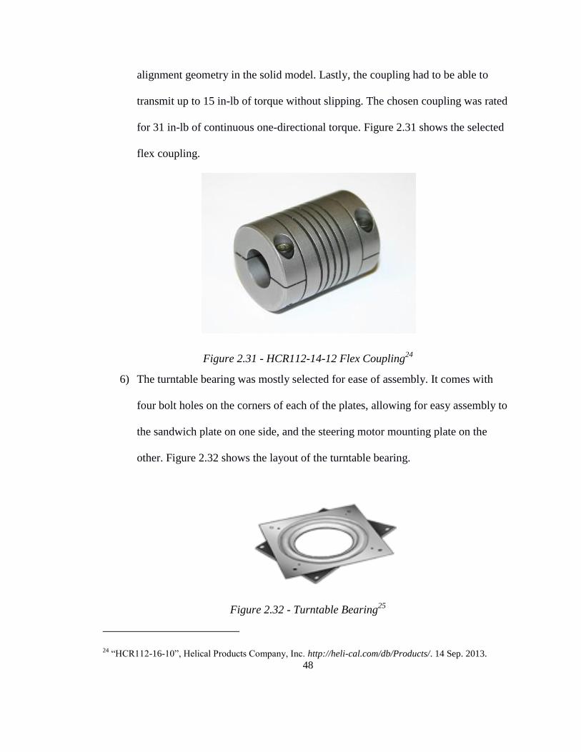
alignment geometry in the solid model. Lastly, the coupling had to be able to
transmit up to 15 in-lb of torque without slipping. The chosen coupling was rated
for 31 in-lb of continuous one-directional torque. Figure 2.31 shows the selected
flex coupling.
Figure 2.31 - HCR112-14-12 Flex Coupling24
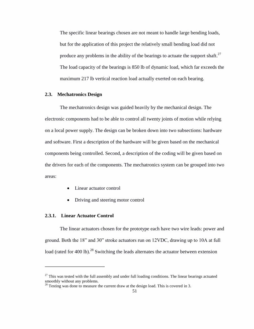
6) The turntable bearing was mostly selected for ease of assembly. It comes with
four bolt holes on the corners of each of the plates, allowing for easy assembly to
the sandwich plate on one side, and the steering motor mounting plate on the
other. Figure 2.32 shows the layout of the turntable bearing.
Figure 2.32 - Turntable Bearing25
24 “HCR112-16-10”, Helical Products Company, Inc. http://heli-cal.com/db/Products/. 14 Sep. 2013.

49
Given that the bearing could handle the compressive load on the leg (this specific
bearing is rated for 200 lb of compressive load), the only remaining concern
would be bending. Since the speed of the device is so slow, there would be no
substantial inertial force that would cause the bearing to bend. This speculation is
not adequate enough for a robust design, however, so testing was later conducted
to verify that any possible bending load the bearing could experience would not
damage the bearing.
7) While there were several different types of linear actuators that would have been
adequate for this project, this specific one was chosen mainly for its slenderness,
robust design, and mounting capabilities. Figure 2.33 shows the linear actuator.
Figure 2.33 - Firgelli Automation FA-400-L-12-30 Linear Actuator26
Two different types were required: 30” stroke for the vertical legs and 18” stroke
25 “Square Turntable”. McMaster-Carr. http://www.mcmaster.com/#lazy-susan-bearings/=nxrsbg. 05 Aug.
2013. 26
400 lb Force 30” Stroke. Firgelli Automations. http://firgelliauto.ca/400lbforce30inchstroke-p-71.html.
05 Aug. 2013.

50
for the horizontal extensions. These designs are exactly the same, the only
variation being their stroke lengths. Both exceed the load requirement of 60 lb by
being able to provide 400 lb of force. This type of actuator moves at 0.5”/sec.,
which is a reasonable speed for the motion of the device. While current draw is
rated for 10A peak, several tests were done under loading to determine that the
actual current draw during application would be between 3-5A. The mounting
hole at the tip of the actuator allows for easy integration with the rest of the
design. A bolt can hold the tip in place inside the tip's specially designed pillow
block.
8) The selection of the linear bearings required three considerations: diameter,
mounting configuration, and load capacity. The diameter was based on the
analysis done on the support shaft. Since a 1” diameter with 1/4” wall thickness
aluminum tubing was chosen, a linear bearing with a 1” inner diameter had to be
selected. For ease of assembly, the type of linear bearings with a mounting block
was chosen. Figure 2.34 shows the linear bearing with its built-in mounting block.
Figure 2.34 - Linear Bearing
51
The specific linear bearings chosen are not meant to handle large bending loads,
but for the application of this project the relatively small bending load did not
produce any problems in the ability of the bearings to actuate the support shaft.27
The load capacity of the bearings is 850 lb of dynamic load, which far exceeds the
maximum 217 lb vertical reaction load actually exerted on each bearing.
2.3. Mechatronics Design
The mechatronics design was guided heavily by the mechanical design. The
electronic components had to be able to control all twenty joints of motion while relying
on a local power supply. The design can be broken down into two subsections: hardware
and software. First a description of the hardware will be given based on the mechanical
components being controlled. Second, a description of the coding will be given based on
the drivers for each of the components. The mechatronics system can be grouped into two
areas:
Linear actuator control
Driving and steering motor control
2.3.1. Linear Actuator Control
The linear actuators chosen for the prototype each have two wire leads: power and
ground. Both the 18” and 30” stroke actuators run on 12VDC, drawing up to 10A at full
load (rated for 400 lb).28
Switching the leads alternates the actuator between extension
27 This was tested with the full assembly and under full loading conditions. The linear bearings actuated
smoothly without any problems. 28
Testing was done to measure the current draw at the design load. This is covered in 3.

52
and retraction.
Since the actuator needs to be able to switch directions, an H-bridge circuit had to
be used. An H-bridge is simply a circuit that acts as a polarity switcher, capable of
switching the leads of a motor from forward to reverse, as well as brake. A simple and
cost-effective solution was running the actuator off of a motor driver. The motor driver
circuit consists of 10 critical pin connections: 1) Motor VIN, 2) Motor GND, 3) Motor
Output 1, 4) Motor Output 2, 5) INA, 6) INB, 7) ENC/DIAG, 8) PWM, 9) 5V board
power, and 10) board ground.29
Motor VIN and GND are for the 12V, high current power input that will
power the linear actuator.
Motor Outputs 1 and 2 are where the two leads from the actuator will be
connected to receive the signal from the board.
INA and INB are the logic pins that will determine the direction of the
actuator (extend or retract).
ENC/DIAG is the pin for either an encoder or a position sensor to
determine the position of the linear actuator’s tip.30
PWM is the pin that controls the amount of voltage going to the actuator.
This controls the speed of actuation.
5V power and ground are the two connections the motor driver itself needs
in order to power the circuit to run the actuator.
29 This configuration is based on the Pololu Robotics and Electronics Dual VNH2SP30 Motor Driver
Carrier MDO3A. 30
While position sensors were not used for this project, it is still important to note that the boards driving
each of the components are capable of receiving signals from such sensors.

53
Since the actuators must all run in pairs, dual motor driver chips were selected.
Figure 2.35 shows the dual motor driver chip.
Figure 2.35 - Pololu VNH2SP30 Dual Motor Driver Board31
The dual motor driver chips are equipped with all the necessary pins in addition to
a second set of Motor Outputs, INAs and INBs, ENC/DIAG, and PWM. To reduce the
number of digital I/O pins required to operate the system, the INA and INB pins of the
two sets of horizontal actuators were soldered together. This way whenever a signal is
sent from the microcontroller to extend or retract, the actuators will move in the same
direction.
In order to run all of the linear actuators, six of the dual motor drivers will be
required. This means there will need to be 20 digital I/O and 12 PWM pins for the
microcontroller to control the linear actuators.32
2.3.2. Driving and Steering Motor Control
The driving and steering motors have conveniently similar specifications. The
31 “Pololu High-Current Dual Driver Carrier Board (VNH2SP30 or VNH3SP30) pinouts”. Pololu Robotics
and Electronics. http://www.pololu.com/catalog/product/708. 05 Aug. 2013. 32
Once encoders are added, there would also need to be 12 analog pins.
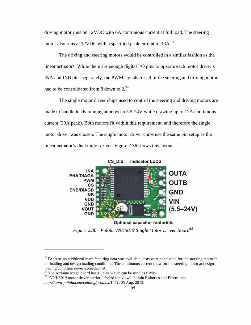
54
driving motor runs on 12VDC with 6A continuous current at full load. The steering
motor also runs at 12VDC with a specified peak current of 13A.33
The driving and steering motors would be controlled in a similar fashion as the
linear actuators. While there are enough digital I/O pins to operate each motor driver’s
INA and INB pins separately, the PWM signals for all of the steering and driving motors
had to be consolidated from 8 down to 2.34
The single motor driver chips used to control the steering and driving motors are
made to handle loads running at between 5.5-24V while drawing up to 12A continuous
current (30A peak). Both motors fit within this requirement, and therefore the single
motor driver was chosen. The single motor driver chips use the same pin setup as the
linear actuator’s dual motor driver. Figure 2.36 shows this layout.
Figure 2.36 - Pololu VNH5019 Single Motor Driver Board35
33 Because no additional manufacturing data was available, tests were conducted for the steering motor in
no-loading and design loading conditions. The continuous current draw for the steering motor at design
loading condition never exceeded 4A. 34
The Arduino Mega board has 15 pins which can be used as PWM. 35
“VNH5019 motor driver carrier, labeled top view”. Pololu Robotics and Electronics.
http://www.pololu.com/catalog/product/1451. 05 Aug. 2013.

55
The resulting motor driver setup for the steering and driving motors will require
16 digital I/O and 2 PWM pins.36
2.3.3. Microprocessor Selection
The two main considerations behind the microprocessor were cost and adequate
number of pins of the correct type. The Arduino Mega 2560 board, run with an
ATmega1280 microprocessor, has a sufficient number of pins of each type to be able to
control all the joints of motion in a somewhat limited fashion. Table 2.14 shows the
available pins, as well as the number of pins required for the prototype’s operation.
Figure 2.37 shows the assembled board.
Table 2.14. Arduino Mega 2560 Pin Usage Breakdown
Pin Type Required Quantity
Digital I/O 36 39
Analog Input 20 16
PWM 14 15
Figure 2.37 - Arduino Mega 256037
36 For position control, 8 analog pins would also be necessary.
37 “Arduino Mega 2560”. Arduino. http://arduino.cc/en/uploads/Main/ArduinoMega2560_R3_Front.jpg.
05 Aug. 2013.

56
While there are a sufficient number of I/O and PWM pins, the Arduino Mega
does not have enough analog inputs to provide for sensors for every joint. This is
acceptable as the scope of the project did not include using sensors. The next version of
the prototype will include sensors for the joints.38
The Arduino Mega can be operated on 12V, but since a laptop would be required
for manual control during testing, the Arduino was simply powered by a USB cable from
the computer.
2.3.4. Power Supplies
There would be two different power supplies on board the device. The first is a
8.4V, low current battery pack used to power the driver chips. The second is a 12V car
battery to power each of the components through the driver chips. Each of these power
supplies are on board per the specification. A car battery was selected for this application
for a few reasons. First, it provides 12VDC, which is the same voltage that all the
individual components need to be operated at. Second, it can provide a large current to
run the device. Third, it is rechargeable.
In order to calculate the necessary amp-hours for a desired amount of operation
time, some estimates had to be made regarding the usage of various components on the
device. The basic estimates were made based on a combination of product data sheets and
number of components.
38 The addition of sensors in future iterations is discussed in 4.

57
Table 2.15. Current Draw Requirements
Type Estimated Continuous
Current at Design Load (A)
Component
Quantity
Total Current
Draw (A)
Actuator 5 12 60
Steering Motor 6 4 24
Driving Motor 6 4 24
If all of the components were to draw their continuous current at design load
simultaneously, then the system would be drawing 108A. The car battery selected has 35
amp-hours, which means the entire system could be operating at full power for 19.4
minutes. This is, of course, an entirely unrealistic estimate since the components will
never all be running at one time. In fact, with the two different types of motion (climbing
stairs and regular driving), there will never be more than 8 components moving at once.
Table 2.16 demonstrates the different operating conditions and their power requirements.
Table 2.16. Current Draw for Various Conditions
Operating
Condition
Motors
On
Actuators
On
Total Current
Draw (A)
Available Time at
Full Current (min)
Climbing Stairs 2 8 52 40
Regular Driving 4 0 24 87
Both of these estimates are worst-case, since only certain stages use eight
actuators. Also, only two motors will be used if the device is driving straight. Only four
are needed during turning and driving. Worst case conditions show the device can run off
of a 35 amp-hr car battery for at least an hour, assuming mostly driving and not a lot of
obstacle or stair climbing. This is enough to show functionality.

58
2.3.5. Overall System Configuration
The Arduino board, batteries, motor drivers, terminal blocks, and surge protection
circuit will all be placed on top of the platform. Figure 2.38 shows a diagram of the
configuration of the electronic components.
Figure 2.38 - Electronic Components Assembly Diagram
Figure 2.38 demonstrates all of the critical connections between the major
components of the circuit. There were three modifications made from the actual setup for
the sake of diagram simplicity. First, the data pins were all lumped together as one
connection going to the microcontroller.39
Second, the high current power and ground
connections from the terminal blocks will each have their own wires, and will not be
39 This is, of course, not the actual configuration. Each PWM, INA, and INB pin will have its own separate
connection to an I/O pin on the microcontroller. Simply because of the number of connections required for
this circuit, placing them all in the diagram would only produce confusion rather than clarity.

59
lumped together as shown in the diagram. Lastly, the power connections coming from the
board terminal blocks will in fact come from two terminal blocks (power and ground)
rather than one.
2.3.6. Software
The purpose of the software is solely to control the motion of the device. Since
the coding is only focused on hardware control, using the Arduino language greatly
simplified the effort required to get functionality. The code accomplishes hardware
control by sending output signals from the MCU’s digital I/O and PWM pins. These
signals are sent via the hardwired connections between the Arduino Mega and the motor
driver chips. The outputs from the I/O pins handle the motor’s INA and INB logic.
The initialization of the software mainly involves declaring several variables to
correspond to the numbered I/O and PWM pins connected to each of the motor driver
chips. The naming scheme identifies the motor driver being referred to. An example is
“int Pair_2_SMotor_L_INA = 22;”. This stands for Pair 2, steering motor, left side40
,
INA pin. The initialization of the function variables, I/O pins, and PWM pins occurs
outside of the main function for global access. When later adaptations of the prototype
are made that include position control, it will no longer be feasible to keep the variable
declarations as global.
There are five variables which are important for the program’s functions. Table
2.17 lays out each variable’s name, assigned initialization value, and purpose.
40 The left or right side is determined from the view of someone sitting on the platform looking forward.

60
Table 2.17. Global Variable Declarations
Variable/Constant
Name
Initialization
Value Purpose
Input_A 0
This variable is the dummy variable used in
the motor driver functions in order to assign a
specific value of true "1" or false "0" to that
motor driver's INA pin. This, along with
Input_B, determines the direction the motor
will spin.
Input_B 0
This variable is the dummy variable used in
the motor driver functions in order to assign a
specific value of true "1" or false "0" to that
motor driver's INA pin. This, along with
Input_A, determines the direction the motor
will spin.
motor_on 70
This is a constant that represents the PWM
value that will be assigned to a specific motor
driver’s PWM pin. Potential values range
from 0-255.
motor_off 0
This is a constant that represents the PWM
value that will be assigned to a specific motor
driver’s PWM pin. Potential values range
from 0-255.
P_W_M_value 0
This variable is the dummy variable used in
the motor driver functions in order to assign a
PWM value to motor driver's PWM pin".
state 0 This variable is used to represent the state
that the program is in.
The structure of the software relies heavily on calling functions to complete
different jobs. The program consists of essentially one “task” which transitions from state
0 to state 1 at the beginning of the program. State 0 is the initialization state, while state 1
is the state in which a lengthy switch-case structure is used for specific commands. The
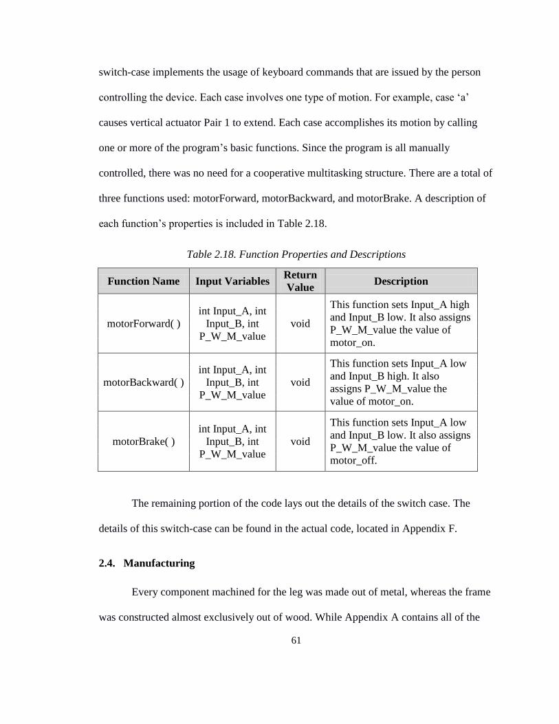
61
switch-case implements the usage of keyboard commands that are issued by the person
controlling the device. Each case involves one type of motion. For example, case ‘a’
causes vertical actuator Pair 1 to extend. Each case accomplishes its motion by calling
one or more of the program’s basic functions. Since the program is all manually
controlled, there was no need for a cooperative multitasking structure. There are a total of
three functions used: motorForward, motorBackward, and motorBrake. A description of
each function’s properties is included in Table 2.18.
Table 2.18. Function Properties and Descriptions
Function Name Input Variables Return
Value Description
motorForward( )
int Input_A, int
Input_B, int
P_W_M_value
void
This function sets Input_A high
and Input_B low. It also assigns
P_W_M_value the value of
motor_on.
motorBackward( )
int Input_A, int
Input_B, int
P_W_M_value
void
This function sets Input_A low
and Input_B high. It also
assigns P_W_M_value the
value of motor_on.
motorBrake( )
int Input_A, int
Input_B, int
P_W_M_value
void
This function sets Input_A low
and Input_B low. It also assigns
P_W_M_value the value of
motor_off.
The remaining portion of the code lays out the details of the switch case. The
details of this switch-case can be found in the actual code, located in Appendix F.
2.4. Manufacturing
Every component machined for the leg was made out of metal, whereas the frame
was constructed almost exclusively out of wood. While Appendix A contains all of the

62
part drawings required to machine these parts, there were several considerations that were
involved in the process.
The only special consideration for the frame base involved reversing the direction
of the actuator holes. Each hole has a slit in order to fit the linear actuator inside of it, and
one half of the base had the slots facing one direction, while the other half had them
facing the reverse direction. Figure 2.39 shows this hole layout.
Figure 2.39 - Frame Base with Opposite-Facing Actuator Slots
The reason for this configuration is that the legs needed to be aligned with each
other, so the center of the circles needed to match up. Also, in order to make the linear
actuator motors overhang on the outside of the platform, the directions of the slots had to
be reversed. The reason that the motors were chosen to face away from the platform was
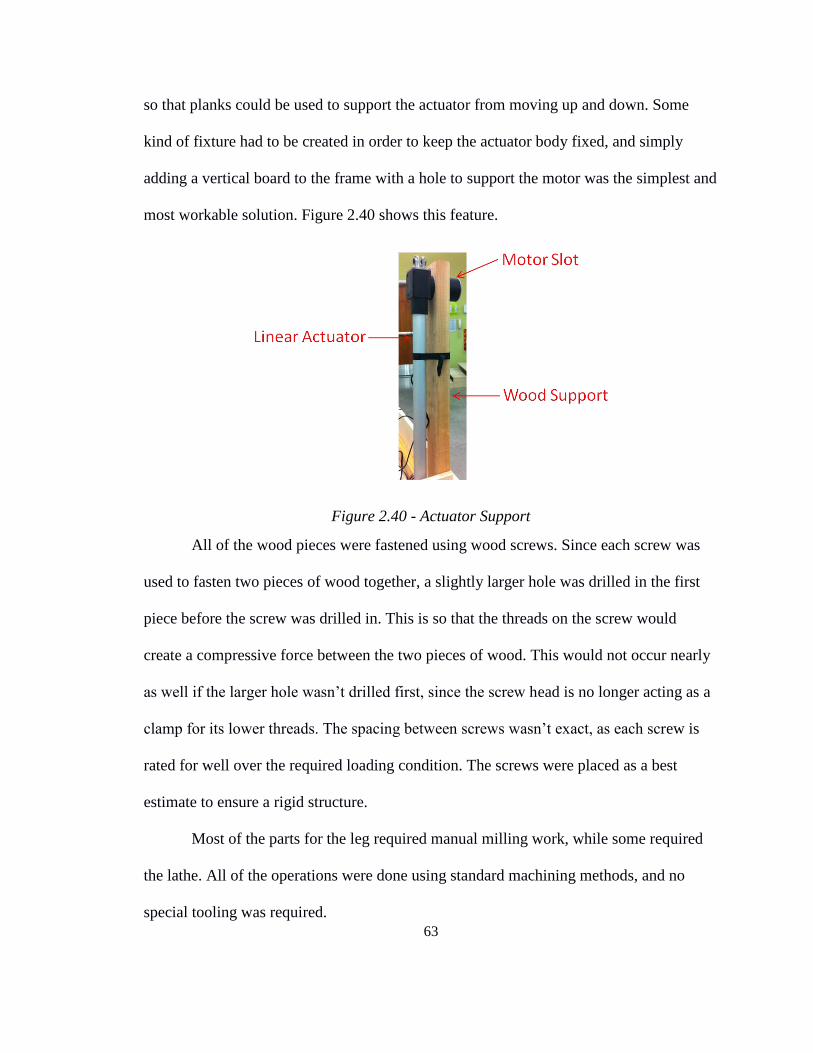
63
so that planks could be used to support the actuator from moving up and down. Some
kind of fixture had to be created in order to keep the actuator body fixed, and simply
adding a vertical board to the frame with a hole to support the motor was the simplest and
most workable solution. Figure 2.40 shows this feature.
Figure 2.40 - Actuator Support
All of the wood pieces were fastened using wood screws. Since each screw was
used to fasten two pieces of wood together, a slightly larger hole was drilled in the first
piece before the screw was drilled in. This is so that the threads on the screw would
create a compressive force between the two pieces of wood. This would not occur nearly
as well if the larger hole wasn’t drilled first, since the screw head is no longer acting as a
clamp for its lower threads. The spacing between screws wasn’t exact, as each screw is
rated for well over the required loading condition. The screws were placed as a best
estimate to ensure a rigid structure.
Most of the parts for the leg required manual milling work, while some required
the lathe. All of the operations were done using standard machining methods, and no
special tooling was required.
64
3. TESTING
3.1. Plan and Objectives
Proving that each of the sequences of motion could be achieved required two
different sets of tests. First, the device had to be able to climb up a set of stairs. Second,
the device had to be able to climb over an arbitrarily shaped but reasonably sized
obstacle. Each of these sets of tests was done by using a laptop keyboard as the
controller, and initiating the correct commands to move the different joints of motion in
stages. This section provides some images of the stages accomplished in the two tests, as
well as any relevant discoveries made about the device by each of these motions.
3.2. Stair Climbing Sequence Tests
The first set of tests was done on the stair climbing sequence. Each of the stages
of this sequence were pre-determined by the sequence laid out in 2.1.4. A specially
fabricated wooden staircase with steps made of 11” x 36” x ¾” thick plywood sheet was
made to allow the device to perform the sequence. As previously discussed, the treads
were kept at their standard length of 11”, while the risers were half-scaled to 4”. The
staircase was placed at the base of Pair 1’s legs, at which point the climbing sequence
could commence. Because many of the stages could be replicated without any structural
issues whatsoever, the entirety of the images of each of the stages of the stair-climbing
sequence are presented in Appendix D.
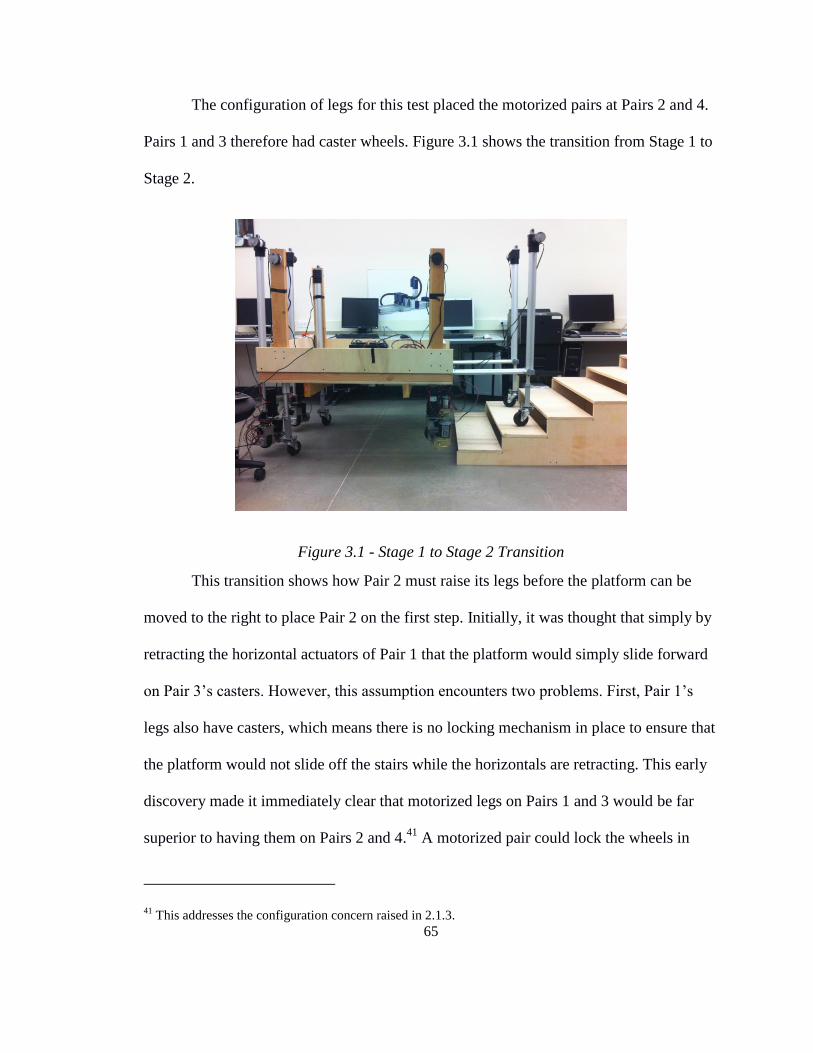
65
The configuration of legs for this test placed the motorized pairs at Pairs 2 and 4.
Pairs 1 and 3 therefore had caster wheels. Figure 3.1 shows the transition from Stage 1 to
Stage 2.
Figure 3.1 - Stage 1 to Stage 2 Transition
This transition shows how Pair 2 must raise its legs before the platform can be
moved to the right to place Pair 2 on the first step. Initially, it was thought that simply by
retracting the horizontal actuators of Pair 1 that the platform would simply slide forward
on Pair 3’s casters. However, this assumption encounters two problems. First, Pair 1’s
legs also have casters, which means there is no locking mechanism in place to ensure that
the platform would not slide off the stairs while the horizontals are retracting. This early
discovery made it immediately clear that motorized legs on Pairs 1 and 3 would be far
superior to having them on Pairs 2 and 4.41
A motorized pair could lock the wheels in
41 This addresses the configuration concern raised in 2.1.3.

66
place, not allowing the platform to slide. The second problem encountered while trying to
accomplish Stage 2 was that the casters weren’t rotating freely enough to ensure that the
platform would move straight forward. The initial angle of the casters would determine
which direction they would slide. Fortunately, these two issues could be overcome by
simultaneously driving the wheels of Pair 4 forward while Pair 1’s horizontal actuators
were retracting. This worked very well to bring the platform forward and allow Pair 2’s
legs to be placed on the first step. The success of this motion is shown in Figure 3.2.
Figure 3.2 - Completion of Stage 2
Each of the remaining even stages (Stage 4, Stage 6, etc.) faced the same issue.
Each time the method of simultaneously retracting Pair 1’s horizontal actuators and
driving Pair 4’s wheels forward worked to bring the platform forward. Thus, up to and
including Stage 9 of the sequence, each stage was successful.

67
The largest difficulties were encountered after Stage 9. The completion of Stage 9
is shown in Figure 3.3.
Figure 3.3 - Completion of Stage 9
In order to transition from Stage 9 to Stage 10, Pairs 2 and 3 must be lifted the
distance of one step to allow the platform to move to the right and place Pairs 2 and 3
back down on the next step. This requires the entire load of the platform to be carried by
Pairs 1 and 4. Up to this point, there had been little issue with placing the full load on
these pairs. However, because of a mechanical issue in the horizontal actuators, the
vertical actuators in Pairs 1 and 4 had a tendency to tilt left-right (into and out of the
page). This created an instability in the system as it was climbing, such that Stage 11
could not be attempted. Risk of crashing was simply too great. In order to even
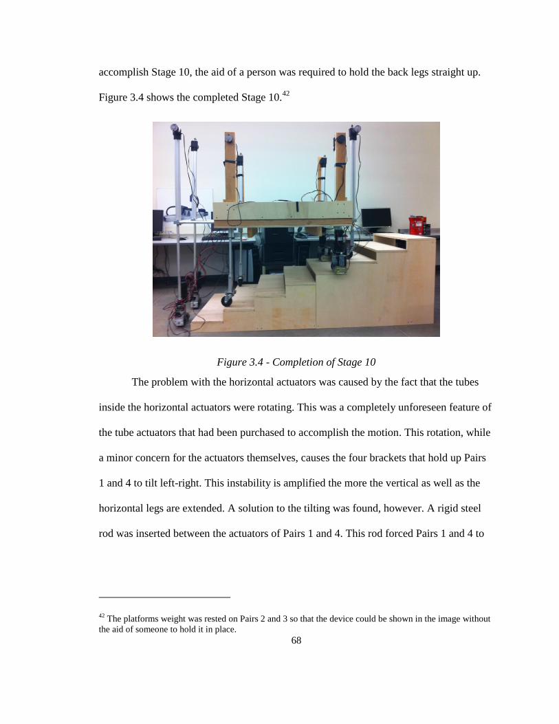
68
accomplish Stage 10, the aid of a person was required to hold the back legs straight up.
Figure 3.4 shows the completed Stage 10.42
Figure 3.4 - Completion of Stage 10
The problem with the horizontal actuators was caused by the fact that the tubes
inside the horizontal actuators were rotating. This was a completely unforeseen feature of
the tube actuators that had been purchased to accomplish the motion. This rotation, while
a minor concern for the actuators themselves, causes the four brackets that hold up Pairs
1 and 4 to tilt left-right. This instability is amplified the more the vertical as well as the
horizontal legs are extended. A solution to the tilting was found, however. A rigid steel
rod was inserted between the actuators of Pairs 1 and 4. This rod forced Pairs 1 and 4 to
42 The platforms weight was rested on Pairs 2 and 3 so that the device could be shown in the image without
the aid of someone to hold it in place.

69
remain mostly straight, thereby dodging the effects of tilting. Figure 3.5 shows the rod
inserted between the actuators.
Figure 3.5 - Rigid Rod Added to Reduce Tilting
In addition to the rigid rod, a different type of actuator, would have aided in
reducing tilting. A final evaluation of the stair climbing sequence tests demonstrates that
the device as designed can complete all stages.
3.3. Obstacle Climbing Sequence Tests
The second set of tests was performed by controlling the device as it traversed an
obstacle. One of the key aspects of the motion during this sequence is for the platform of
the device to stay stable and flat as it is carried over an obstacle. The beginning of the
sequence involved the vehicle rolling up to the obstacle with Pair 1’s vertical legs
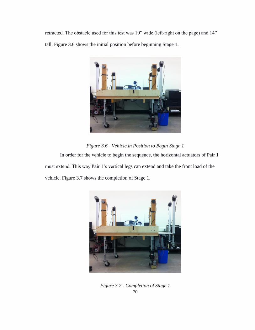
70
retracted. The obstacle used for this test was 10” wide (left-right on the page) and 14”
tall. Figure 3.6 shows the initial position before beginning Stage 1.
Figure 3.6 - Vehicle in Position to Begin Stage 1
In order for the vehicle to begin the sequence, the horizontal actuators of Pair 1
must extend. This way Pair 1’s vertical legs can extend and take the front load of the
vehicle. Figure 3.7 shows the completion of Stage 1.
Figure 3.7 - Completion of Stage 1

71
According to the original diagrams, Stage 2 involves lowering Pair 1 while raising
both Pairs 2 and 3. Because of the instability of Pair 1 and Pair 4’s legs while extended,
only Pair 2 was raised. This is acceptable until Pair 3’s legs must travel over the obstacle.
The test failed, however, while attempting to complete Stage 3a. Figure 3.8 shows an
image of the device at Stage 2, prior to failure.
Figure 3.8 - Completion of Stage 2
When looking at Pair 1 in this image, it is clear that the same tilting issue
experienced in the first set of tests is also being experienced here. Even with the addition
of the rigid rod to reduce tilting, the twisting in the horizontal actuators themselves
caused enough of an issue to discontinue the testing at this point. An attempt was made to
commence Stage 3a, which involved using the drive motors of Pair 4 to drive the device
forward. Only about one second after the drive motors turned on, Pair 1’s legs completely
gave way and the vehicle crashed on its front-left corner. Nothing was damaged or

72
displaced during the crash, but it became clear that accomplishing the obstacle climbing
sequence would have to be done with a smaller obstacle.
It is important to note that many of the design features were verified during the
testing stages. The steering and driving both functioned adequately on all four legs. The
wooden supports for vertical actuators of Pairs 2 and 3 functioned properly to keep the
actuators straight up and down. The platform itself demonstrated more than enough
rigidity, even when it crashed. Lastly, all of the electronics worked as-designed, giving
full functionality for the steering, driving, and motion of the linear actuators.
Because the device lacked position control, the climbing sequences had to be
accomplished using manual control. Because exact positions could not be achieved, an
efficient way of surmounting this problem was by fine-tuning the PWM values of each of
the motor drivers to force each of the actuators to move at the same speed. Due to stiction
on the inside of the linear actuators, each of them were prone to move at different speeds.
By changing the PWM values so that each actuator in a pair matched the speed of the
other, the sequences required less manual tuning in between stages. This not only saved
time during the testing process, it also laid the grounds for additional features to be added
for the next version of the prototype.
In order to accomplish each stage of any given sequence, it is obvious that
position control be ultimately involved. This ensures that the device can stop at a specific
location, while also paving the way for the device to be pre-programmed with certain
sequences so that the driver would not have to control a device with so many joints of
motion. Tweaking the PWM values, however, also revealed the need for velocity control

73
in addition to position control. If all of the actuators can be ensured to move at the same
speed, the platform can be ensured to stay level. Adjusting PWM values is not a final
solution, but it did show that the platform could stay flat during the motion in each
sequence.
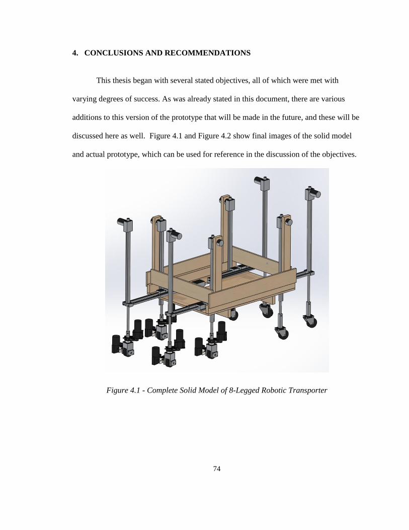
74
4. CONCLUSIONS AND RECOMMENDATIONS
This thesis began with several stated objectives, all of which were met with
varying degrees of success. As was already stated in this document, there are various
additions to this version of the prototype that will be made in the future, and these will be
discussed here as well. Figure 4.1 and Figure 4.2 show final images of the solid model
and actual prototype, which can be used for reference in the discussion of the objectives.
Figure 4.1 - Complete Solid Model of 8-Legged Robotic Transporter
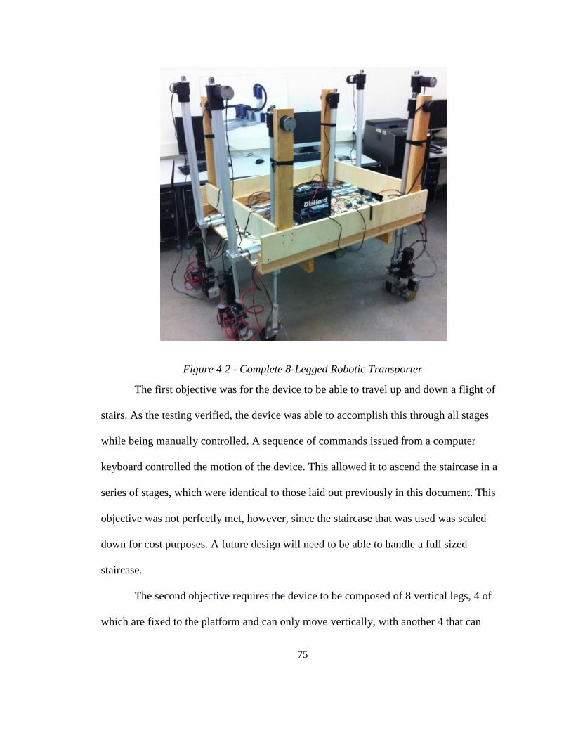
75
Figure 4.2 - Complete 8-Legged Robotic Transporter
The first objective was for the device to be able to travel up and down a flight of
stairs. As the testing verified, the device was able to accomplish this through all stages
while being manually controlled. A sequence of commands issued from a computer
keyboard controlled the motion of the device. This allowed it to ascend the staircase in a
series of stages, which were identical to those laid out previously in this document. This
objective was not perfectly met, however, since the staircase that was used was scaled
down for cost purposes. A future design will need to be able to handle a full sized
staircase.
The second objective requires the device to be composed of 8 vertical legs, 4 of
which are fixed to the platform and can only move vertically, with another 4 that can
76
move horizontally as well as vertically. This goal was achieved by using 12 different
linear actuators – 8 vertical and 4 horizontal. The 4 horizontal actuators were shielded
from bending by placing a hollow aluminum shaft parallel to it, which took all of the
gravity load of the device. While all the actuators would typically move in pairs during
all modes of motion, both the mechanical hardware and the software allow each of the
actuators to move independently of each other. As discovered during the testing, the
horizontal actuators had a problem with rotation. This would eventually have to be fixed
by choosing a different type of actuators for the design.
The third objective was to place a weight on top of the platform to simulate the
transportation of cargo or persons. While the mechanical components for this prototype
were not designed to be able to carry a person, a 30 lb car battery was placed on the
platform to simulate the weight as well as perform the critical task of supplying power.
The fourth objective required that the device be powered with an on-board supply.
This came in three forms. First, a car battery was used to supply high-current power to
the components through the motor driver chips. Second, a separate 8.4V, low amperage
battery pack was used to power the chips. Third, the USB cable connected to the laptop
computer powered the Arduino Mega 2560. While this was not necessary, the cable was
required in order to send keyboard commands, making it redundant to supply power from
the 8.4V battery pack. If needed, however, the battery pack could serve this function.
The fifth objective states that the platform on the device stay level at all times.
Without position control, this was challenging. Ultimately, manual control was able to
bring the actuators close to, but not perfect, alignment. The main reason for this
discrepancy is that the linear actuators did not have linear encoders, making it impossible
77
to give feedback that could have ensured that all actuators were extended to the same
length. Since the actuators extend and retract at different speeds because of internal
stiction, the legs had to be independently adjusted to achieve a reasonable state of
levelness. Despite the setbacks of having no position control, the lack of encoders did not
stop the device from being able to sufficiently demonstrate all stages of motion in the
testing phase. It is important to note that the lack of levelness that resulted was not a
problem with the mechanical design, simply a problem with the system not containing
components necessary for position control. For scope and cost reasons, these components
were saved for a future iteration of the prototype.
Given the relative success of each of these five objectives, it is important that a
general conclusion be made. The results of the research done in this thesis indicate that
pursuing a further iteration of this device is warranted. None of the issues encountered
are insurmountable. That being said, there are still several problems that were
encountered that need to be addressed for future iterations of the design. While most of
these changes constitute additional features which are outside the scope of the objectives
of this thesis, there are a few that represent improvements of design decisions made for
this prototype.
There are several changes that could be implemented to enhance the current
design. First, there were several parts of the prototype that were simply too large. The 4
ft. x 3 ft. platform is bulky and could be downsized. Now that there is a prototype that
spells out what electronic components are required to make the device run, a future
iteration could use this information to fill the available space more efficiently. The 3 ft.
width could be reduced comfortably by 6-8 inches without causing any concern for either
78
tipping or having enough space for electronics. The objective here would be to reduce the
width such that the device could comfortably fit between the rails of most staircases. The
4 ft. length dimension could be reduced at the cost of offsetting the horizontal actuators.
The original reason 4 ft. was chosen was to allow for opposing horizontal actuators to be
collinear. If one were to reduce the 48 inches required in order to fit two 18-inch stroke
actuators, they would have to be placed side by side.43
Another option would be to place
the horizontal actuators on top of each other, so that overlap would not result in offsetting
the vertical actuators. Placing the actuators on top of each other would likely require that
a different type of linear actuator be chosen entirely, however. This is because the right
angle of the motor to the stroke makes it difficult to stack it on top of another of the same
type. An important note on this option is that if the actuator type were to change for the
vertical legs, several of the mechanical components would have to be completely
redesigned. However, if only the horizontal actuators were changed, very few mechanical
components would require redesign. As discussed previously, the usage of track actuators
would be far preferable to tube actuators. Track actuators would provide substantial
additional rigidity to avoid the issue of twisting that caused some of the later stages of the
testing to fail.
Another group of components that are simply too cumbersome are the drive and
steering motors. Many components were designed to accommodate such motors, which
were selected for cost reasons. A future iteration would want to include smaller motors, if
possible. This would allow the drive and steering portion of the prototype to shrink in
43 If the 18” stroke length was to increase, it would also be difficult to reduce the 4 ft. dimension.
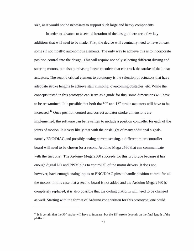
79
size, as it would not be necessary to support such large and heavy components.
In order to advance to a second iteration of the design, there are a few key
additions that will need to be made. First, the device will eventually need to have at least
some (if not mostly) autonomous elements. The only way to achieve this is to incorporate
position control into the design. This will require not only selecting different driving and
steering motors, but also purchasing linear encoders that can track the stroke of the linear
actuators. The second critical element to autonomy is the selection of actuators that have
adequate stroke lengths to achieve stair climbing, overcoming obstacles, etc. While the
concepts tested in this prototype can serve as a guide for this, some dimensions will have
to be reexamined. It is possible that both the 30” and 18” stroke actuators will have to be
increased.44
Once position control and correct actuator stroke dimensions are
implemented, the software can be rewritten to include a position controller for each of the
joints of motion. It is very likely that with the onslaught of many additional signals,
namely ENC/DIAG and possibly analog current sensing, a different microcontroller
board will need to be chosen (or a second Arduino Mega 2560 that can communicate
with the first one). The Arduino Mega 2560 succeeds for this prototype because it has
enough digital I/O and PWM pins to control all of the motor drivers. It does not,
however, have enough analog inputs or ENC/DIAG pins to handle position control for all
the motors. In this case that a second board is not added and the Arduino Mega 2560 is
completely replaced, it is also possible that the coding platform will need to be changed
as well. Starting with the format of Arduino code written for this prototype, one could
44 It is certain that the 30” stroke will have to increase, but the 18” stroke depends on the final length of the
platform.

80
expand and create adequate code for a semi-autonomous device.
Another feature that could be added to simplify the hardware and increase the
aesthetic appeal is to control the motor drivers remotely. This would remove the need for
the excessive number of data wires that were required in order to make this prototype
function. While power would still have to be supplied by a hard line, all of the data
transmission could be accomplished with remote signals.

81
BIBLIOGRAPHY
[1] Goren Michael; Goren, Jeremy E. Stair-Climbing Human Transporter. U.S. Patent
7,246,671, July 24, 2007.
[2] “Drive Wheel Motor Torque Calculations”, EML2322L – MAE Design and
Manufacturing Laboratory. University of Florida. 03 Aug. 2013.
http://www2.mae.ufl.edu/designlab/motors/EML2322L%20Drive%20Wheel%20
Motor%20Torque%20Calculations.pdf
[3] McGraw Hill. Shigley’s Mechanical Engineering Design 9th
Edition. New York: The
McGraw-Hill Companies, Inc. 2011. Print.
[4] “Timing Belt Theory”, Gates Mectrol Inc., 2006.
http://www.thomasnet.com/white-papers/abstract/101106/timing-belt-theory.html
[5] Young and Freedman. University Physics 12th
Edition. San Francisco: Pearson
Education, Inc. 2008. Print.

82
Appendix A: PART DRAWINGS
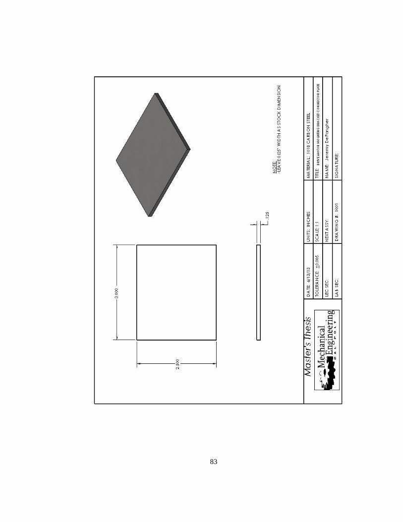
83

84

85
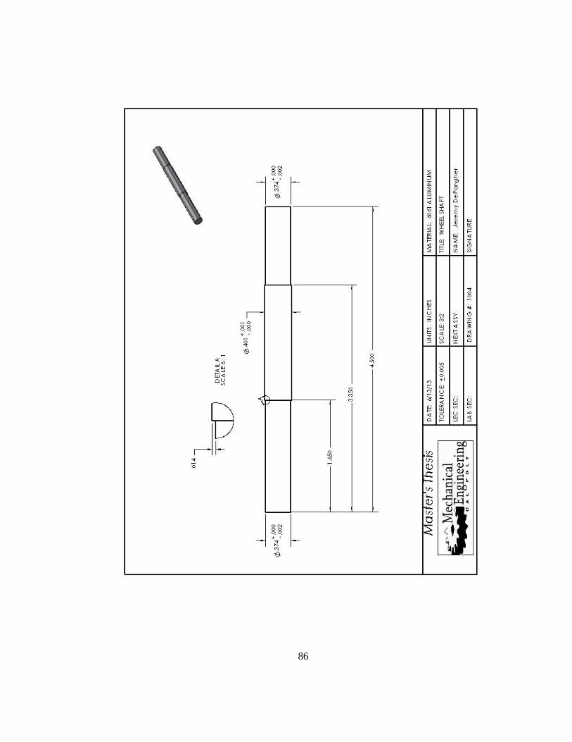
86
87

88
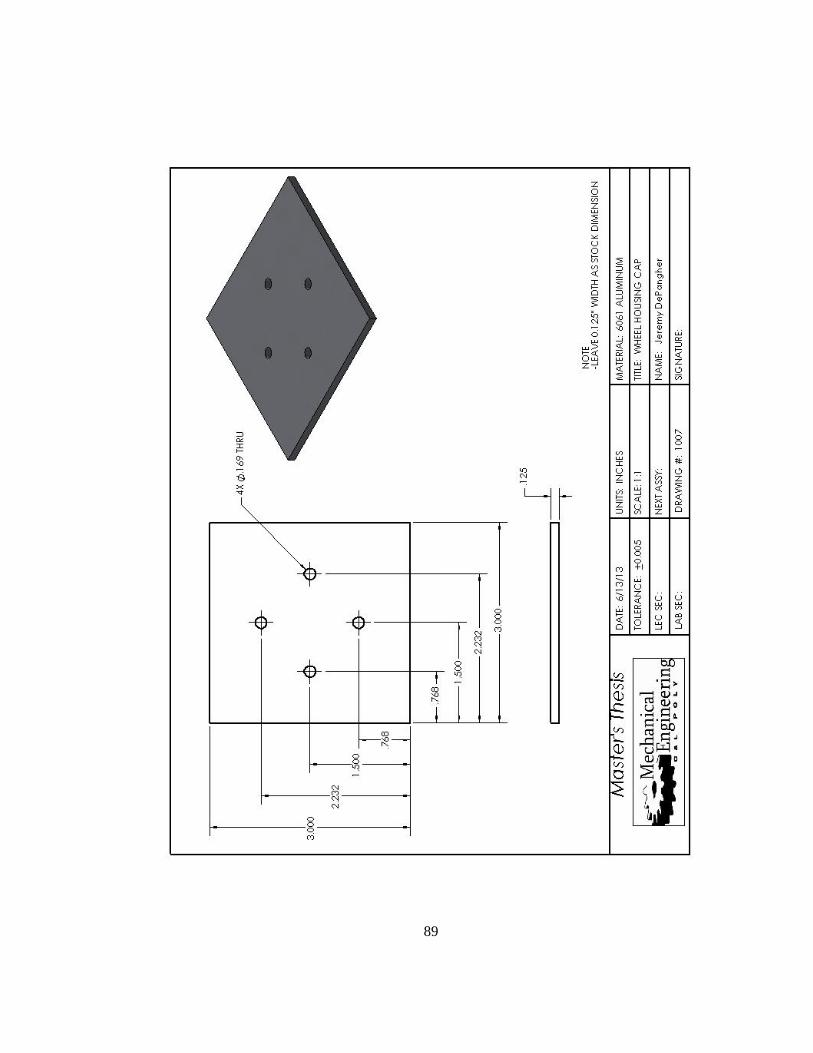
89

90

91

92
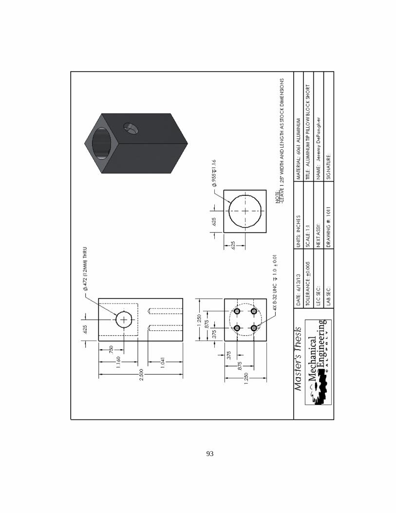
93

94
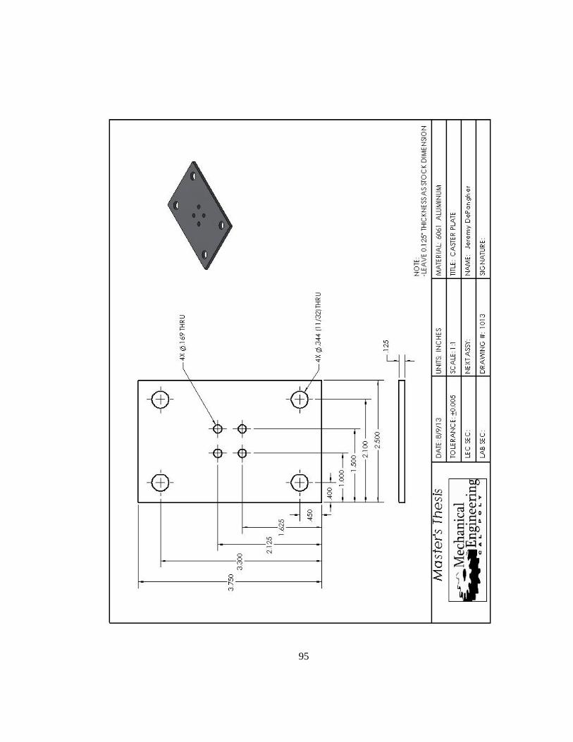
95

96

97

98

99
Appendix B: ENGINEERING CALCULATIONS

100
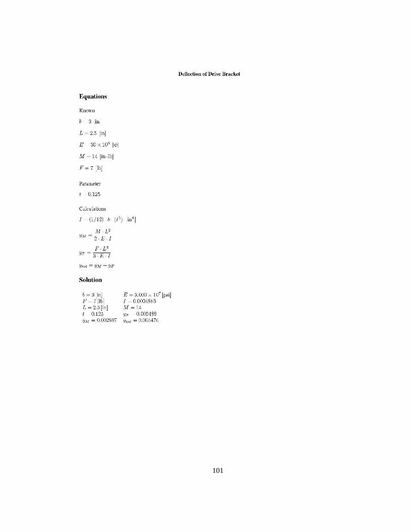
101

102
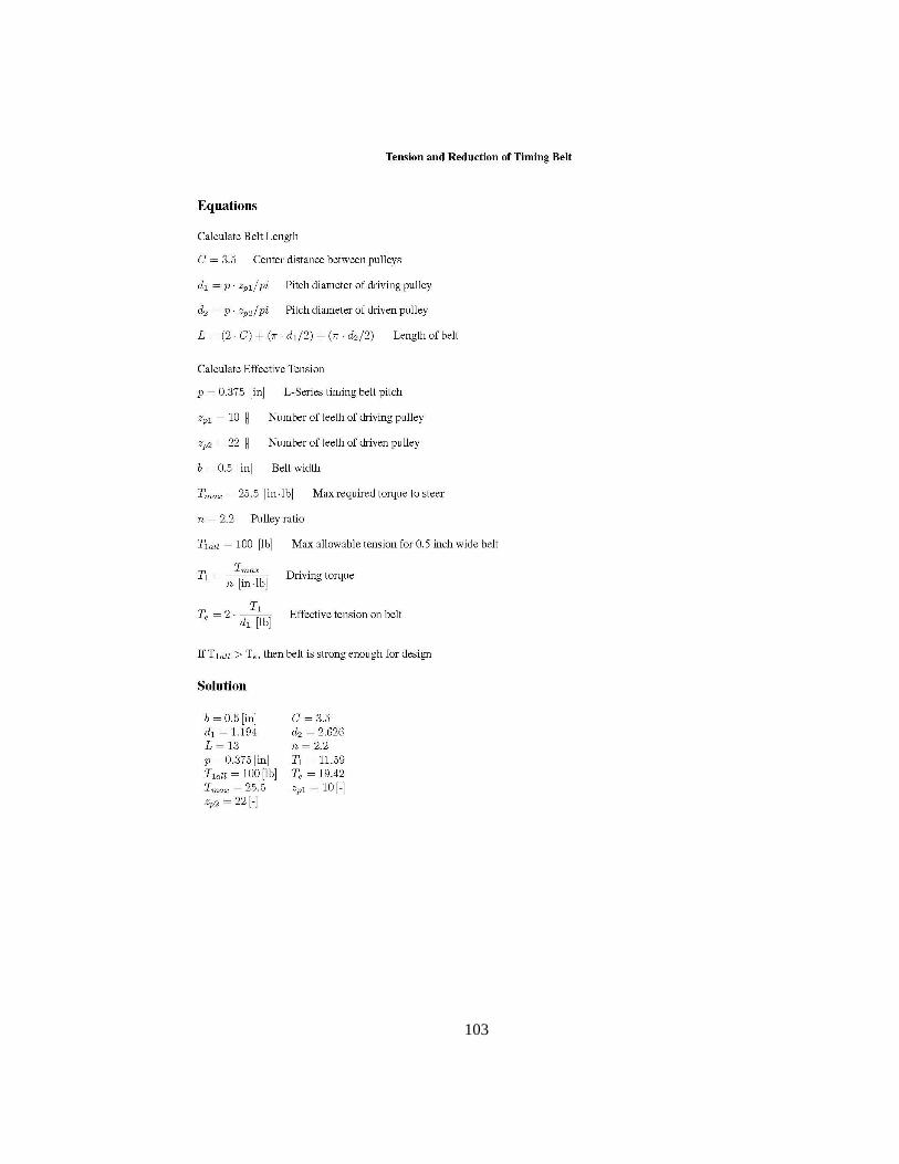
103

104
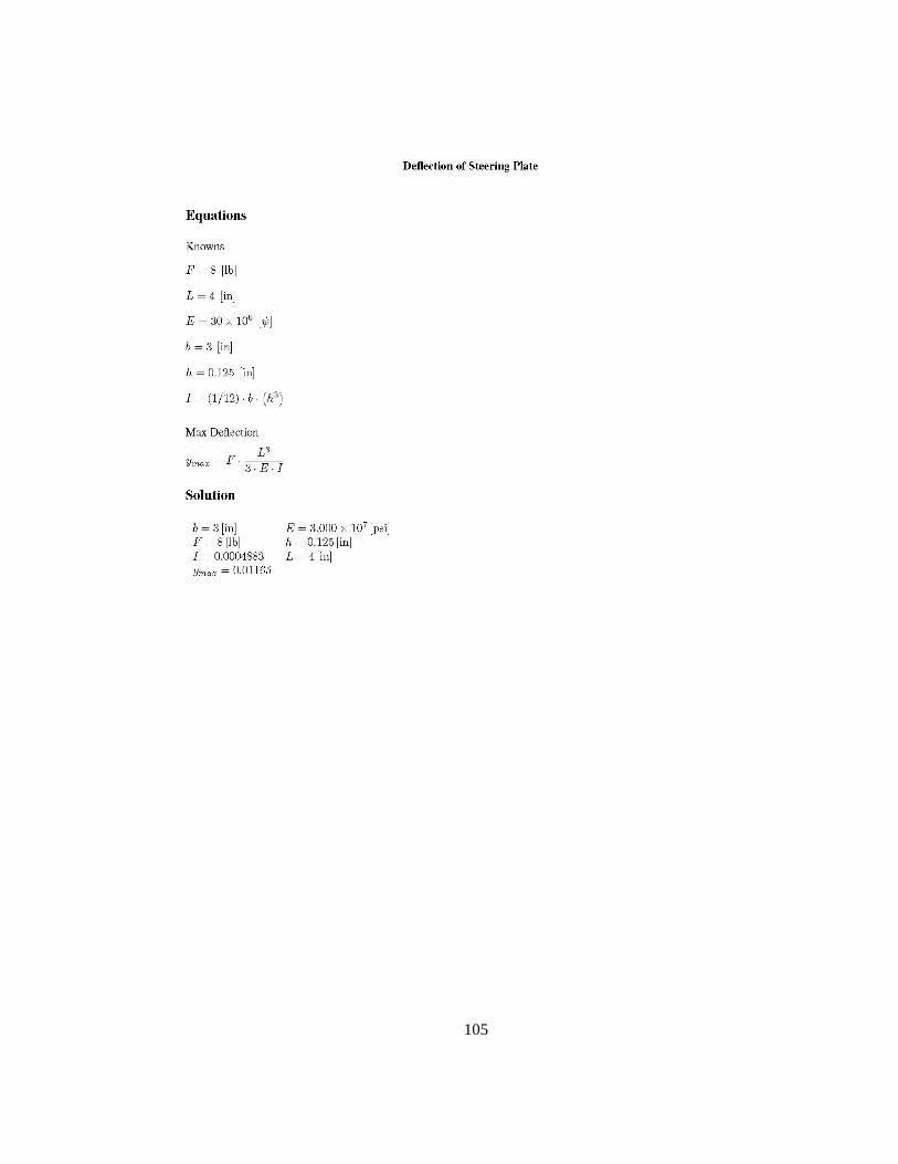
105

106

107

108
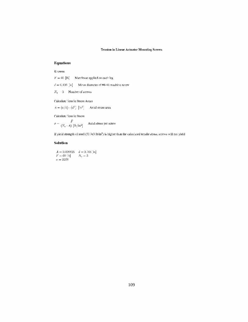
109

110

111
Appendix C: BILL OF MATERIALS
Table C.1. Bill of Materials
Component Description Quantity
Right angle gearmotor 100 RPM, 12VDC 4
Inline gearmotor 20 RPM, 12VDC 4
Driving motor bracket Connector plate 4
Flex coupling HCR112-14-12, 7/16" and 3/8" bores 4
Bearing pillow block Pillow block for thrust bearings 8
Banded ball thrust bearings 0.375" bore 8
Wheel shaft Shaft for drive wheel 4
Rubber wheel - 4
Caster rubber wheel assembly - 4
Caster plate - 4
Wheel housing Housing for drive wheel 4
Large pulley 22 teeth, 2.875" OD 4
Small pulley 10 teeth, 1.438" OD, with setscrew 4
Timing belt L-series, 130L050 4
Turntable sandwich plate - 4
Turntable bearing - 4
Steering motor mounting plate - 4
Aluminum tip pillow block
short
Block connecting actuator tip to
motorized leg assembly 4
Aluminum tip pillow block
long
Block connecting actuator tip to caster
leg assembly 4
30" stroke linear actuator - 8
18" stroke linear actuator - 4
Vertical connector block Connects 30" linear actuators to 18"
linear actuators and parallel support shaft 2
Vertical connector block
reverse
Connects 30" linear actuators to 18"
linear actuators and parallel support shaft 2
Linear pillow block bearing - 8
Parallel support shaft Supports horizontal actuators from
bending 4
Plywood base 36" x 48" x 3/4" 1
Plywood side supports 6" x 48" x 3/4" 2
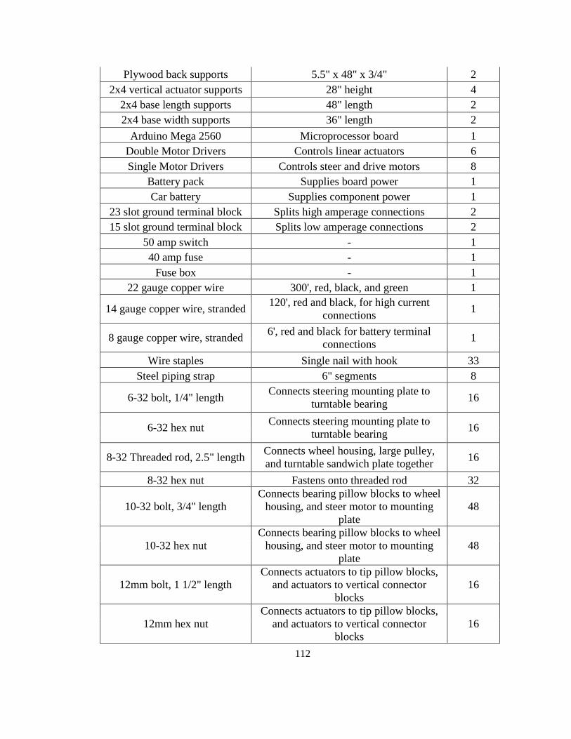
112
Plywood back supports 5.5" x 48" x 3/4" 2
2x4 vertical actuator supports 28" height 4
2x4 base length supports 48" length 2
2x4 base width supports 36" length 2
Arduino Mega 2560 Microprocessor board 1
Double Motor Drivers Controls linear actuators 6
Single Motor Drivers Controls steer and drive motors 8
Battery pack Supplies board power 1
Car battery Supplies component power 1
23 slot ground terminal block Splits high amperage connections 2
15 slot ground terminal block Splits low amperage connections 2
50 amp switch - 1
40 amp fuse - 1
Fuse box - 1
22 gauge copper wire 300', red, black, and green 1
14 gauge copper wire, stranded 120', red and black, for high current
connections 1
8 gauge copper wire, stranded 6', red and black for battery terminal
connections 1
Wire staples Single nail with hook 33
Steel piping strap 6" segments 8
6-32 bolt, 1/4" length Connects steering mounting plate to
turntable bearing 16
6-32 hex nut Connects steering mounting plate to
turntable bearing 16
8-32 Threaded rod, 2.5" length Connects wheel housing, large pulley,
and turntable sandwich plate together 16
8-32 hex nut Fastens onto threaded rod 32
10-32 bolt, 3/4" length
Connects bearing pillow blocks to wheel
housing, and steer motor to mounting
plate
48
10-32 hex nut
Connects bearing pillow blocks to wheel
housing, and steer motor to mounting
plate
48
12mm bolt, 1 1/2" length
Connects actuators to tip pillow blocks,
and actuators to vertical connector
blocks
16
12mm hex nut
Connects actuators to tip pillow blocks,
and actuators to vertical connector
blocks
16
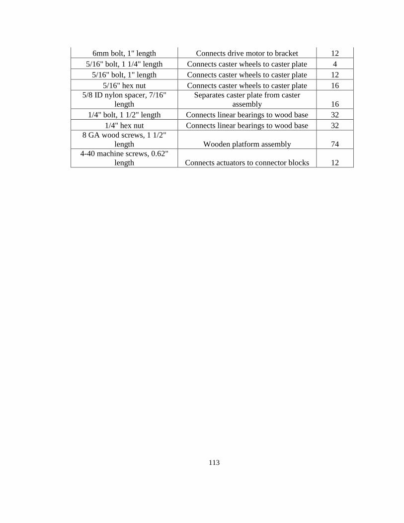
113
6mm bolt, 1" length Connects drive motor to bracket 12
5/16" bolt, 1 1/4" length Connects caster wheels to caster plate 4
5/16" bolt, 1" length Connects caster wheels to caster plate 12
5/16" hex nut Connects caster wheels to caster plate 16
5/8 ID nylon spacer, 7/16"
length
Separates caster plate from caster
assembly 16
1/4" bolt, 1 1/2" length Connects linear bearings to wood base 32
1/4" hex nut Connects linear bearings to wood base 32
8 GA wood screws, 1 1/2"
length Wooden platform assembly 74
4-40 machine screws, 0.62"
length Connects actuators to connector blocks 12

114
Appendix D: DATA SHEETS
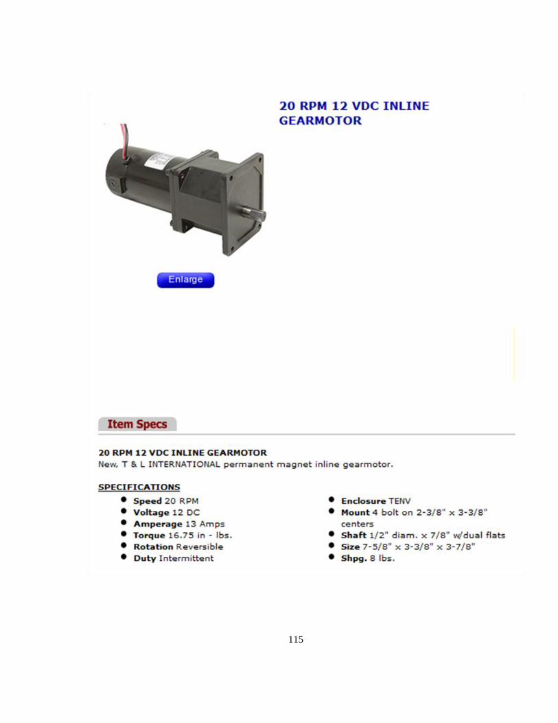
115

116

117
Appendix E: SEQUENCE TESTING IMAGES
Figure E.1 - Stair Climbing Stage 1
Figure E.2 - Stair Climbing Stage 2

118
Figure E.3 - Stair Climbing Stage 3
Figure E.4 - Stair Climbing Stage 4
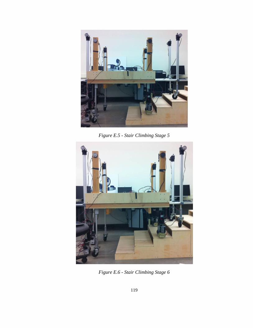
119
Figure E.5 - Stair Climbing Stage 5
Figure E.6 - Stair Climbing Stage 6
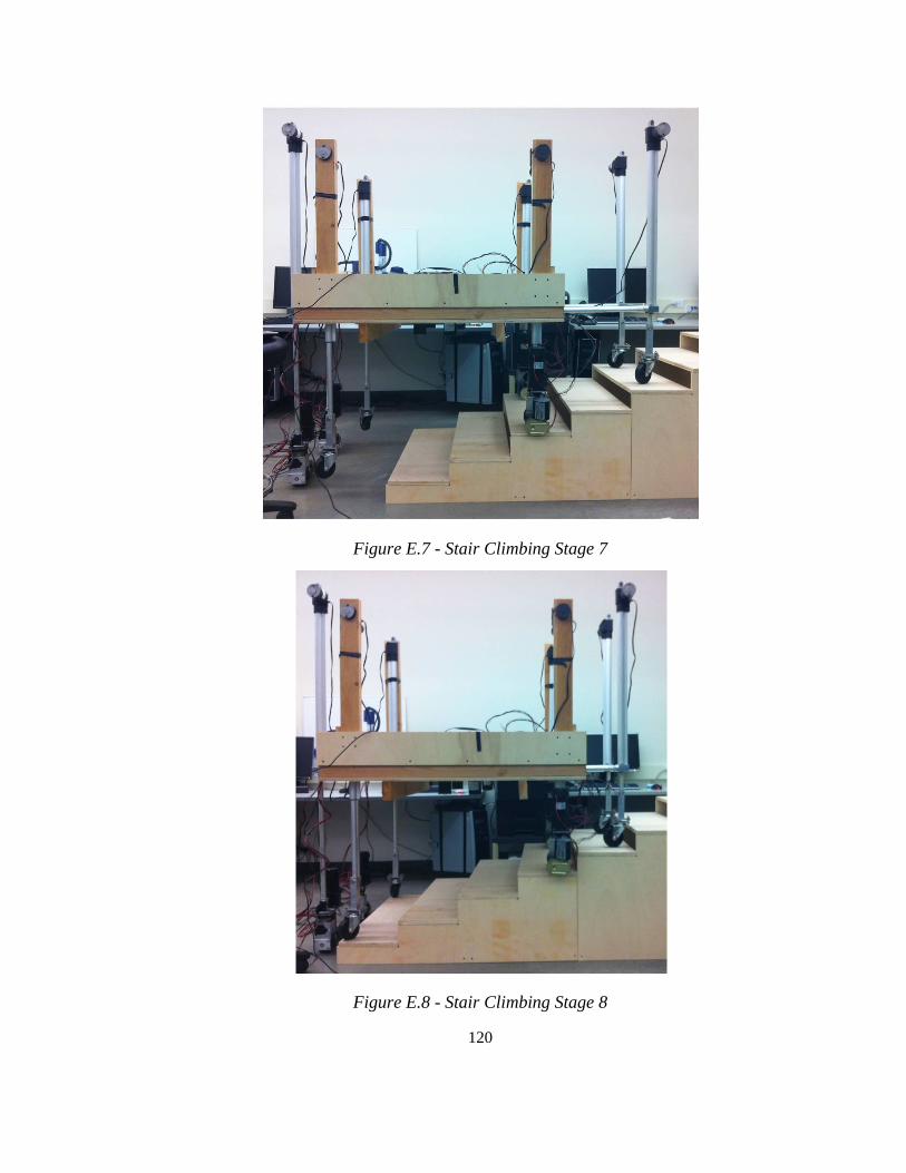
120
Figure E.7 - Stair Climbing Stage 7
Figure E.8 - Stair Climbing Stage 8
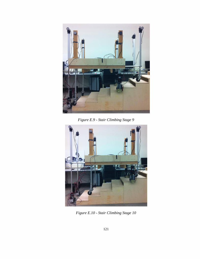
121
Figure E.9 - Stair Climbing Stage 9
Figure E.10 - Stair Climbing Stage 10

122
Appendix F: SOFTWARE CODE
/*
Manual controller for an 8-legged robotic transporter
This code allows 20 different joints of motion to be controlled manually
by inputting keyboard commands.
*/
int Input_A = 0; // Function variable for INA pins
int Input_B = 0; // Function variable for INB pins
int P_W_M_value = 0; // Function variable for PWM pins
int motor_speed = 0; // Function variable for varying motor speed
int motor_1L = 160; // PWM value for Pair 1 actuator left side
int motor_1R = 160; // PWM value for Pair 1 actuator right side
int motor_2L = 150; // PWM value for Pair 2 actuator left side
int motor_2R = 90; // PWM value for Pair 2 actuator right side
int motor_3L = 150; // PWM value for Pair 3 actuator left side
int motor_3R = 190; // PWM value for Pair 3 actuator right side
int motor_4L = 220; // PWM value for Pair 4 actuator left side
int motor_4R = 150; // PWM value for Pair 4 actuator right side
int motor_5L = 255; // PWM value for front horizontal pair left side
int motor_5R = 90; // PWM value for front horizontal pair right side
int motor_6L = 120; // PWM value for back horizontal pair left side
int motor_6R = 120; // PWM value for back horizontal pair right side
int motor_on = 70; // Constant for PWM value assigned to drive and steer motors
int motor_off = 0; // Constant to turn off motors
int state = 0; // State variable for switch-case
//Pair 2, Left Side
int Pair_2_SMotor_L_INA = 52; // INA of the left steering motor for Pair 2
int Pair_2_SMotor_L_INB = 53; // INB of the left steering motor for Pair 2
int Pair_2_DMotor_L_INA = 14; // INA of the left drive motor for Pair 2
int Pair_2_DMotor_L_INB = 15; // INB of the left drive motor for Pair 2
//Pair 2, Right Side
int Pair_2_SMotor_R_INA = 16; // INA of the right steering motor for Pair 2
int Pair_2_SMotor_R_INB = 17; // INB of the right steering motor for Pair 2
int Pair_2_DMotor_R_INA = 18; // INA of the right drive motor for Pair 2
int Pair_2_DMotor_R_INB = 20; // INB of the right drive motor for Pair 2
//Pair 4, Left Side
int Pair_4_SMotor_L_INA = 22; // INA of the left steering motor for Pair 4
int Pair_4_SMotor_L_INB = 23; // INB of the left steering motor for Pair 4
int Pair_4_DMotor_L_INA = 24; // INA of the left drive motor for Pair 4
int Pair_4_DMotor_L_INB = 25; // INB of the left drive motor for Pair 4
//Pair 4, Right Side
int Pair_4_SMotor_R_INA = 26; // INA of the right steering motor for Pair 4
int Pair_4_SMotor_R_INB = 27; // INB of the right steering motor for Pair 4
int Pair_4_DMotor_R_INA = 28; // INA of the right drive motor for Pair 4
int Pair_4_DMotor_R_INB = 29; // INB of the right drive motor for Pair 4
//Digital I/O and PWM pin declarations
int SMotor_PWM = 2; // PWM of steering motors
int DMotor_PWM = 3; // PWM of driving motors
//Pair 1, Vertical Actuators
int Pair_1_VActuator_L_INA = 30; // INA of the vertical acutators, Pair 1, left side
int Pair_1_VActuator_L_INB = 31; // INB of the vertical acutators, Pair 1, left side
int Pair_1_VActuator_L_PWM = 4; // PWM of the vertical actuators, Pair 1, left side
int Pair_1_VActuator_R_INA = 32; // INA of the vertical acutators, Pair 1, right side
int Pair_1_VActuator_R_INB = 33; // INB of the vertical acutators, Pair 1, right side
int Pair_1_VActuator_R_PWM = 5; // PWM of the vertical actuators, Pair 1, right side
//Pair 2, Vertical Actuators
int Pair_2_VActuator_L_INA = 34; // INA of the vertical acutators, Pair 2, left side
int Pair_2_VActuator_L_INB = 35; // INB of the vertical acutators, Pair 2, left side
int Pair_2_VActuator_L_PWM = 6; // PWM of the vertical actuators, Pair 2, left side
int Pair_2_VActuator_R_INA = 36; // INA of the vertical acutators, Pair 2, right side
123
int Pair_2_VActuator_R_INB = 37; // INB of the vertical acutators, Pair 2, right side
int Pair_2_VActuator_R_PWM = 7; // PWM of the vertical actuators, Pair 2, right side
//Pair 3, Vertical Actuators
int Pair_3_VActuator_L_INA = 38; // INA of the vertical acutators, Pair 3, left side
int Pair_3_VActuator_L_INB = 39; // INB of the vertical acutators, Pair 3, left side
int Pair_3_VActuator_L_PWM = 8; // PWM of the vertical actuators, Pair 3, left side
int Pair_3_VActuator_R_INA = 40; // INA of the vertical acutators, Pair 3, right side
int Pair_3_VActuator_R_INB = 41; // INB of the vertical acutators, Pair 3, right side
int Pair_3_VActuator_R_PWM = 9; // PWM of the vertical actuators, Pair 3, right side
//Pair 4, Vertical Actuators
int Pair_4_VActuator_L_INA = 42; // INA of the vertical acutators, Pair 4, left side
int Pair_4_VActuator_L_INB = 43; // INB of the vertical acutators, Pair 4, left side
int Pair_4_VActuator_L_PWM = 10; // PWM of the vertical actuators, Pair 4, left side
int Pair_4_VActuator_R_INA = 50; // INA of the vertical acutators, Pair 4, right side
int Pair_4_VActuator_R_INB = 51; // INB of the vertical acutators, Pair 4, right side
int Pair_4_VActuator_R_PWM = 11; // PWM of the vertical actuators, Pair 4, right side
//Front Horizontal Actuator Pair
int Front_HActuators_INA = 47; // INA of the front horizontal actuators
int Front_HActuators_INB = 44; // INB of the front horizontal actuators
int Front_HActuator_L_PWM = 45; // PWM of the front horizontal actuators, left side
int Front_HActuator_R_PWM = 46; // PWM of the front horizontal actuators, right side
//Back Horizontal Actuator Pair
int Back_HActuators_INA = 48; // INA of the back horizontal actuators
int Back_HActuators_INB = 49; // INB of the back horizontal actuators
int Back_HActuator_L_PWM = 12; // PWM of the back horizontal actuators, left side
int Back_HActuator_R_PWM = 13; // PWM of the back horizontal actuators, right side
// The setup routine runs once when you press reset
void setup()
{
Serial.begin(9600);
// Declares Driving and Steering motor pins as outputs:
pinMode(Pair_2_SMotor_L_INA, OUTPUT);
pinMode(Pair_2_SMotor_L_INB, OUTPUT);
pinMode(Pair_2_DMotor_L_INA, OUTPUT);
pinMode(Pair_2_DMotor_L_INB, OUTPUT);
pinMode(Pair_2_SMotor_R_INA, OUTPUT);
pinMode(Pair_2_SMotor_R_INB, OUTPUT);
pinMode(Pair_2_DMotor_R_INA, OUTPUT);
pinMode(Pair_2_DMotor_R_INB, OUTPUT);
pinMode(Pair_4_SMotor_L_INA, OUTPUT);
pinMode(Pair_4_SMotor_L_INB, OUTPUT);
pinMode(Pair_4_DMotor_L_INA, OUTPUT);
pinMode(Pair_4_DMotor_L_INB, OUTPUT);
pinMode(Pair_4_SMotor_R_INA, OUTPUT);
pinMode(Pair_4_SMotor_R_INB, OUTPUT);
pinMode(Pair_4_DMotor_R_INA, OUTPUT);
pinMode(Pair_4_DMotor_R_INB, OUTPUT);
pinMode(SMotor_PWM, OUTPUT);
pinMode(DMotor_PWM, OUTPUT);
// Declares Actuator pins as outputs:
pinMode(Pair_1_VActuator_L_INA, OUTPUT);
pinMode(Pair_1_VActuator_L_INB, OUTPUT);
pinMode(Pair_1_VActuator_L_PWM, OUTPUT);
pinMode(Pair_1_VActuator_R_INA, OUTPUT);
pinMode(Pair_1_VActuator_R_INB, OUTPUT);
pinMode(Pair_1_VActuator_R_PWM, OUTPUT);
pinMode(Pair_2_VActuator_L_INA, OUTPUT);
pinMode(Pair_2_VActuator_L_INB, OUTPUT);
pinMode(Pair_2_VActuator_L_PWM, OUTPUT);
pinMode(Pair_2_VActuator_R_INA, OUTPUT);
pinMode(Pair_2_VActuator_R_INB, OUTPUT);
pinMode(Pair_2_VActuator_R_PWM, OUTPUT);
pinMode(Pair_3_VActuator_L_INA, OUTPUT);
pinMode(Pair_3_VActuator_L_INB, OUTPUT);
pinMode(Pair_3_VActuator_L_PWM, OUTPUT);

124
pinMode(Pair_3_VActuator_R_INA, OUTPUT);
pinMode(Pair_3_VActuator_R_INB, OUTPUT);
pinMode(Pair_3_VActuator_R_PWM, OUTPUT);
pinMode(Pair_4_VActuator_L_INA, OUTPUT);
pinMode(Pair_4_VActuator_L_INB, OUTPUT);
pinMode(Pair_4_VActuator_L_PWM, OUTPUT);
pinMode(Pair_4_VActuator_R_INA, OUTPUT);
pinMode(Pair_4_VActuator_R_INB, OUTPUT);
pinMode(Pair_4_VActuator_R_PWM, OUTPUT);
pinMode(Front_HActuators_INA, OUTPUT);
pinMode(Front_HActuators_INB, OUTPUT);
pinMode(Front_HActuator_L_PWM, OUTPUT);
pinMode(Front_HActuator_R_PWM, OUTPUT);
pinMode(Back_HActuators_INA, OUTPUT);
pinMode(Back_HActuators_INB, OUTPUT);
pinMode(Back_HActuator_L_PWM, OUTPUT);
pinMode(Back_HActuator_R_PWM, OUTPUT);
// Default all pin outputs to low
analogWrite(SMotor_PWM, motor_off);
analogWrite(DMotor_PWM, motor_off);
digitalWrite(Pair_2_SMotor_L_INA, LOW);
digitalWrite(Pair_2_SMotor_L_INB, LOW);
digitalWrite(Pair_2_DMotor_L_INA, LOW);
digitalWrite(Pair_2_DMotor_L_INB, LOW);
digitalWrite(Pair_2_SMotor_R_INA, LOW);
digitalWrite(Pair_2_SMotor_R_INB, LOW);
digitalWrite(Pair_2_DMotor_R_INA, LOW);
digitalWrite(Pair_2_DMotor_R_INB, LOW);
digitalWrite(Pair_4_SMotor_L_INA, LOW);
digitalWrite(Pair_4_SMotor_L_INB, LOW);
digitalWrite(Pair_4_DMotor_L_INA, LOW);
digitalWrite(Pair_4_DMotor_L_INB, LOW);
digitalWrite(Pair_4_SMotor_R_INA, LOW);
digitalWrite(Pair_4_SMotor_R_INB, LOW);
digitalWrite(Pair_4_DMotor_R_INA, LOW);
digitalWrite(Pair_4_DMotor_R_INB, LOW);
digitalWrite(Pair_1_VActuator_L_INA, LOW);
digitalWrite(Pair_1_VActuator_L_INB, LOW);
analogWrite(Pair_1_VActuator_L_PWM, motor_off);
digitalWrite(Pair_1_VActuator_R_INA, LOW);
digitalWrite(Pair_1_VActuator_R_INB, LOW);
analogWrite(Pair_1_VActuator_R_PWM, motor_off);
digitalWrite(Pair_2_VActuator_L_INA, LOW);
digitalWrite(Pair_2_VActuator_L_INB, LOW);
analogWrite(Pair_2_VActuator_L_PWM, motor_off);
digitalWrite(Pair_2_VActuator_R_INA, LOW);
digitalWrite(Pair_2_VActuator_R_INB, LOW);
analogWrite(Pair_2_VActuator_R_PWM, motor_off);
digitalWrite(Pair_3_VActuator_L_INA, LOW);
digitalWrite(Pair_3_VActuator_L_INB, LOW);
analogWrite(Pair_3_VActuator_L_PWM, motor_off);
digitalWrite(Pair_3_VActuator_R_INA, LOW);
digitalWrite(Pair_3_VActuator_R_INB, LOW);
analogWrite(Pair_3_VActuator_R_PWM, motor_off);
digitalWrite(Pair_4_VActuator_L_INA, LOW);
digitalWrite(Pair_4_VActuator_L_INB, LOW);
analogWrite(Pair_4_VActuator_L_PWM, motor_off);
digitalWrite(Pair_4_VActuator_R_INA, LOW);
digitalWrite(Pair_4_VActuator_R_INB, LOW);
analogWrite(Pair_4_VActuator_R_PWM, motor_off);
digitalWrite(Front_HActuators_INA, LOW);
digitalWrite(Front_HActuators_INB, LOW);
analogWrite(Front_HActuator_L_PWM, motor_off);
analogWrite(Front_HActuator_R_PWM, motor_off);

125
digitalWrite(Back_HActuators_INA, LOW);
digitalWrite(Back_HActuators_INB, LOW);
analogWrite(Back_HActuator_L_PWM, motor_off);
analogWrite(Back_HActuator_R_PWM, motor_off);
}
// Function for causing a motor to rotate in the "forward" direction
void motorForward(int Input_A, int Input_B, int P_W_M_value, int motor_speed)
{
digitalWrite(Input_A, HIGH); // Sets all motor power connections (red cable) to high
digitalWrite(Input_B, LOW); // Sets all motor ground connections (black cable) to low
analogWrite(P_W_M_value, motor_speed); // Updates the value of the PWM to the specified value
}
// Function for causing a motor to rotate in the "backward" direction
void motorBackward(int Input_A, int Input_B, int P_W_M_value, int motor_speed)
{
digitalWrite(Input_A, LOW); // Sets all motor power connections (red cable) to low
digitalWrite(Input_B, HIGH); // Sets all motor ground connections (black cable) to high
analogWrite(P_W_M_value, motor_speed);// Updates the value of the PWM to the specified value
}
// Function for causing a motor to stop
void motorBrake(int Input_A, int Input_B, int P_W_M_value)
{
digitalWrite(Input_A, LOW); // Sets all motor power connections (red cable) to low
digitalWrite(Input_B, LOW); // Sets all motor ground connections (black cable) to high
analogWrite(P_W_M_value, motor_off); // Updates the value of the PWM to zero
}
// The loop routine runs over and over again forever
void loop()
{
// send data only when you receive data:
if (Serial.available() > 0)
{
// read the incoming byte:
state = Serial.read();
// Switch-Case for motor selection goes here
switch(state)
{
case '1': // Case for extending Actuator Pair 1
{
motorForward(Pair_1_VActuator_L_INA, Pair_1_VActuator_L_INB, Pair_1_VActuator_L_PWM, motor_1L);
motorForward(Pair_1_VActuator_R_INA, Pair_1_VActuator_R_INB, Pair_1_VActuator_R_PWM, motor_1R);
}
break;
case '2': // Case for retracting Actuator Pair 1
{
motorBackward(Pair_1_VActuator_L_INA, Pair_1_VActuator_L_INB, Pair_1_VActuator_L_PWM, motor_1L);
motorBackward(Pair_1_VActuator_R_INA, Pair_1_VActuator_R_INB, Pair_1_VActuator_R_PWM, motor_1R);
}
break;
case '3': // Case for extending Actuator Pair 2
{
motorForward(Pair_2_VActuator_L_INA, Pair_2_VActuator_L_INB, Pair_2_VActuator_L_PWM, motor_2L);
motorForward(Pair_2_VActuator_R_INA, Pair_2_VActuator_R_INB, Pair_2_VActuator_R_PWM, motor_2R);
}
break;
case '4': // Case for retracting Actuator Pair 2
{
motorBackward(Pair_2_VActuator_L_INA, Pair_2_VActuator_L_INB, Pair_2_VActuator_L_PWM, motor_2L);
motorBackward(Pair_2_VActuator_R_INA, Pair_2_VActuator_R_INB, Pair_2_VActuator_R_PWM, motor_2R);
}
break;
case '5': // Case for extending Actuator Pair 3
{
motorForward(Pair_3_VActuator_L_INA, Pair_3_VActuator_L_INB, Pair_3_VActuator_L_PWM, motor_3L);
motorForward(Pair_3_VActuator_R_INA, Pair_3_VActuator_R_INB, Pair_3_VActuator_R_PWM, motor_3R);
}
break;
case '6': // Case for retracting Actuator Pair 3
{
motorBackward(Pair_3_VActuator_L_INA, Pair_3_VActuator_L_INB, Pair_3_VActuator_L_PWM, motor_3L);
motorBackward(Pair_3_VActuator_R_INA, Pair_3_VActuator_R_INB, Pair_3_VActuator_R_PWM, motor_3R);
}

126
break;
case '7': // Case for extending Actuator Pair 4
{
motorForward(Pair_4_VActuator_L_INA, Pair_4_VActuator_L_INB, Pair_4_VActuator_L_PWM, motor_4L);
motorForward(Pair_4_VActuator_R_INA, Pair_4_VActuator_R_INB, Pair_4_VActuator_R_PWM, motor_4R);
}
break;
case '8': // Case for retracting Actuator Pair 4
{
motorBackward(Pair_4_VActuator_L_INA, Pair_4_VActuator_L_INB, Pair_4_VActuator_L_PWM, motor_4L);
motorBackward(Pair_4_VActuator_R_INA, Pair_4_VActuator_R_INB, Pair_4_VActuator_R_PWM, motor_4R);
}
break;
case '9': // Case for extending Actuator Pairs 2 and 3
{
motorForward(Pair_2_VActuator_L_INA, Pair_2_VActuator_L_INB, Pair_2_VActuator_L_PWM, motor_2L);
motorForward(Pair_2_VActuator_R_INA, Pair_2_VActuator_R_INB, Pair_2_VActuator_R_PWM, motor_2R);
motorForward(Pair_3_VActuator_L_INA, Pair_3_VActuator_L_INB, Pair_3_VActuator_L_PWM, motor_3L);
motorForward(Pair_3_VActuator_R_INA, Pair_3_VActuator_R_INB, Pair_3_VActuator_R_PWM, motor_3R);
}
break;
case '10': // Case for retracting Actuator Pairs 2 and 3
{
motorBackward(Pair_2_VActuator_L_INA, Pair_2_VActuator_L_INB, Pair_2_VActuator_L_PWM, motor_2L);
motorBackward(Pair_2_VActuator_R_INA, Pair_2_VActuator_R_INB, Pair_2_VActuator_R_PWM, motor_2R);
motorBackward(Pair_3_VActuator_L_INA, Pair_3_VActuator_L_INB, Pair_3_VActuator_L_PWM, motor_3L);
motorBackward(Pair_3_VActuator_R_INA, Pair_3_VActuator_R_INB, Pair_3_VActuator_R_PWM, motor_3R);
}
break;
case '11': // Case for extending Actuator Pairs 1 and 4
{
motorForward(Pair_1_VActuator_L_INA, Pair_1_VActuator_L_INB, Pair_1_VActuator_L_PWM, motor_1L);
motorForward(Pair_1_VActuator_R_INA, Pair_1_VActuator_R_INB, Pair_1_VActuator_R_PWM, motor_1R);
motorForward(Pair_4_VActuator_L_INA, Pair_4_VActuator_L_INB, Pair_4_VActuator_L_PWM, motor_4L);
motorForward(Pair_4_VActuator_R_INA, Pair_4_VActuator_R_INB, Pair_4_VActuator_R_PWM, motor_4R);
}
break;
case '12': // Case for retracting Actuator Pairs 1 and 4
{
motorBackward(Pair_1_VActuator_L_INA, Pair_1_VActuator_L_INB, Pair_1_VActuator_L_PWM, motor_1L);
motorBackward(Pair_1_VActuator_R_INA, Pair_1_VActuator_R_INB, Pair_1_VActuator_R_PWM, motor_1R);
motorBackward(Pair_4_VActuator_L_INA, Pair_4_VActuator_L_INB, Pair_4_VActuator_L_PWM, motor_4L);
motorBackward(Pair_4_VActuator_R_INA, Pair_4_VActuator_R_INB, Pair_4_VActuator_R_PWM, motor_4R);
}
break;
case '13': // Case for extending Actuator Pairs 1 and 3
{
motorForward(Pair_1_VActuator_L_INA, Pair_1_VActuator_L_INB, Pair_1_VActuator_L_PWM, motor_1L);
motorForward(Pair_1_VActuator_R_INA, Pair_1_VActuator_R_INB, Pair_1_VActuator_R_PWM, motor_1R);
motorForward(Pair_3_VActuator_L_INA, Pair_3_VActuator_L_INB, Pair_3_VActuator_L_PWM, motor_3L);
motorForward(Pair_3_VActuator_R_INA, Pair_3_VActuator_R_INB, Pair_3_VActuator_R_PWM, motor_3R);
}
break;
case '14': // Case for retracting Actuator Pairs 1 and 3
{
motorBackward(Pair_1_VActuator_L_INA, Pair_1_VActuator_L_INB, Pair_1_VActuator_L_PWM, motor_1L);
motorBackward(Pair_1_VActuator_R_INA, Pair_1_VActuator_R_INB, Pair_1_VActuator_R_PWM, motor_1R);
motorBackward(Pair_3_VActuator_L_INA, Pair_3_VActuator_L_INB, Pair_3_VActuator_L_PWM, motor_3L);
motorBackward(Pair_3_VActuator_R_INA, Pair_3_VActuator_R_INB, Pair_3_VActuator_R_PWM, motor_3R);
}
break;
case '15': // Case for extending Actuator Pairs 2 and 4
{
motorForward(Pair_2_VActuator_L_INA, Pair_2_VActuator_L_INB, Pair_2_VActuator_L_PWM, motor_2L);
motorForward(Pair_2_VActuator_R_INA, Pair_2_VActuator_R_INB, Pair_2_VActuator_R_PWM, motor_2R);
motorForward(Pair_4_VActuator_L_INA, Pair_4_VActuator_L_INB, Pair_4_VActuator_L_PWM, motor_4L);
motorForward(Pair_4_VActuator_R_INA, Pair_4_VActuator_R_INB, Pair_4_VActuator_R_PWM, motor_4R);
}
break;
case '16': // Case for retracting Actuator Pairs 2 and 4
{
motorBackward(Pair_2_VActuator_L_INA, Pair_2_VActuator_L_INB, Pair_2_VActuator_L_PWM, motor_2L);
motorBackward(Pair_2_VActuator_R_INA, Pair_2_VActuator_R_INB, Pair_2_VActuator_R_PWM, motor_2R);
motorBackward(Pair_4_VActuator_L_INA, Pair_4_VActuator_L_INB, Pair_4_VActuator_L_PWM, motor_4L);
motorBackward(Pair_4_VActuator_R_INA, Pair_4_VActuator_R_INB, Pair_4_VActuator_R_PWM, motor_4R);
}
break;
case 'a': // Case for extending front horizontal actuators

127
{
motorForward(Front_HActuators_INA, Front_HActuators_INB, Front_HActuator_L_PWM, motor_5L);
motorForward(Front_HActuators_INA, Front_HActuators_INB, Front_HActuator_R_PWM, motor_5R);
}
break;
case 'b': // Case for retracting front horizontal actuators
{
motorBackward(Front_HActuators_INA, Front_HActuators_INB, Front_HActuator_L_PWM, motor_5L);
motorBackward(Front_HActuators_INA, Front_HActuators_INB, Front_HActuator_R_PWM, motor_5R);
}
break;
case 'c': // Case for extending back horizontal actuators
{
motorForward(Back_HActuators_INA, Back_HActuators_INB, Back_HActuator_L_PWM, motor_6L);
motorForward(Back_HActuators_INA, Back_HActuators_INB, Back_HActuator_R_PWM, motor_6R);
}
break;
case 'd': // Case for retracting back horizontal actuators
{
motorBackward(Back_HActuators_INA, Back_HActuators_INB, Back_HActuator_L_PWM, motor_6L);
motorBackward(Back_HActuators_INA, Back_HActuators_INB, Back_HActuator_R_PWM, motor_6R);
}
break;
case 'q': // Case for steering Pair 2 to the right
{
motorForward(Pair_2_SMotor_L_INA, Pair_2_SMotor_L_INB, SMotor_PWM, motor_on);
motorForward(Pair_2_SMotor_R_INA, Pair_2_SMotor_R_INB, SMotor_PWM, motor_on);
}
break;
case 'w': // Case for steering Pair 2 to the left
{
motorBackward(Pair_2_SMotor_L_INA, Pair_2_SMotor_L_INB, SMotor_PWM, motor_on);
motorBackward(Pair_2_SMotor_R_INA, Pair_2_SMotor_R_INB, SMotor_PWM, motor_on);
}
break;
case 'e': // Case for steering Pair 4 to the right
{
motorForward(Pair_4_SMotor_L_INA, Pair_4_SMotor_L_INB, SMotor_PWM, motor_on);
motorForward(Pair_4_SMotor_R_INA, Pair_4_SMotor_R_INB, SMotor_PWM, motor_on);
}
break;
case 'r': // Case for steering Pair 4 to the left
{
motorBackward(Pair_4_SMotor_L_INA, Pair_4_SMotor_L_INB, SMotor_PWM, motor_on);
motorBackward(Pair_4_SMotor_R_INA, Pair_4_SMotor_R_INB, SMotor_PWM, motor_on);
}
break;
case 't': // Case for driving Pair 2 forward
{
motorForward(Pair_2_DMotor_L_INA, Pair_2_DMotor_L_INB, DMotor_PWM, motor_on);
motorForward(Pair_2_DMotor_R_INA, Pair_2_DMotor_R_INB, DMotor_PWM, motor_on);
}
break;
case 'y': // Case for driving Pair 2 backward
{
motorBackward(Pair_2_DMotor_L_INA, Pair_2_DMotor_L_INB, DMotor_PWM, motor_on);
motorBackward(Pair_2_DMotor_R_INA, Pair_2_DMotor_R_INB, DMotor_PWM, motor_on);
}
break;
case 'u': // Case for driving Pair 4 forward
{
motorForward(Pair_4_DMotor_L_INA, Pair_4_DMotor_L_INB, DMotor_PWM, motor_on);
motorForward(Pair_4_DMotor_R_INA, Pair_4_DMotor_R_INB, DMotor_PWM, motor_on);
}
break;
case 'i': // Case for driving Pair 4 backward
{
motorBackward(Pair_4_DMotor_L_INA, Pair_4_DMotor_L_INB, DMotor_PWM, motor_on);
motorBackward(Pair_4_DMotor_R_INA, Pair_4_DMotor_R_INB, DMotor_PWM, motor_on);
}
break;
case 's': // Case for stopping all motors
{
motorBrake(Pair_1_VActuator_L_INA, Pair_1_VActuator_L_INB, Pair_1_VActuator_L_PWM);
motorBrake(Pair_1_VActuator_R_INA, Pair_1_VActuator_R_INB, Pair_1_VActuator_R_PWM);
motorBrake(Pair_2_VActuator_L_INA, Pair_2_VActuator_L_INB, Pair_2_VActuator_L_PWM);
motorBrake(Pair_2_VActuator_R_INA, Pair_2_VActuator_R_INB, Pair_2_VActuator_R_PWM);
motorBrake(Pair_3_VActuator_L_INA, Pair_3_VActuator_L_INB, Pair_3_VActuator_L_PWM);

128
motorBrake(Pair_3_VActuator_R_INA, Pair_3_VActuator_R_INB, Pair_3_VActuator_R_PWM);
motorBrake(Pair_4_VActuator_L_INA, Pair_4_VActuator_L_INB, Pair_4_VActuator_L_PWM);
motorBrake(Pair_4_VActuator_R_INA, Pair_4_VActuator_R_INB, Pair_4_VActuator_R_PWM);
motorBrake(Front_HActuators_INA, Front_HActuators_INB, Front_HActuator_L_PWM);
motorBrake(Front_HActuators_INA, Front_HActuators_INB, Front_HActuator_R_PWM);
motorBrake(Back_HActuators_INA, Back_HActuators_INB, Back_HActuator_L_PWM);
motorBrake(Back_HActuators_INA, Back_HActuators_INB, Back_HActuator_R_PWM);
motorBrake(Pair_2_DMotor_L_INA, Pair_2_DMotor_L_INB, DMotor_PWM);
motorBrake(Pair_2_DMotor_R_INA, Pair_2_DMotor_R_INB, DMotor_PWM);
motorBrake(Pair_4_DMotor_L_INA, Pair_4_DMotor_L_INB, DMotor_PWM);
motorBrake(Pair_4_DMotor_R_INA, Pair_4_DMotor_R_INB, DMotor_PWM);
motorBrake(Pair_2_SMotor_L_INA, Pair_2_SMotor_L_INB, SMotor_PWM);
motorBrake(Pair_2_SMotor_R_INA, Pair_2_SMotor_R_INB, SMotor_PWM);
motorBrake(Pair_4_SMotor_L_INA, Pair_4_SMotor_L_INB, SMotor_PWM);
motorBrake(Pair_4_SMotor_R_INA, Pair_4_SMotor_R_INB, SMotor_PWM);
}
break;
default:
Serial.print("Not a valid command.");
}
}