design and implementation of an immersive virtual … · design and implementation of an immersive...
TRANSCRIPT
Design and Implementation of an Immersive Virtual Reality System basedon a Smartphone Platform
Anthony Steed∗, Simon Julier†
Department of Computer Science, University College London
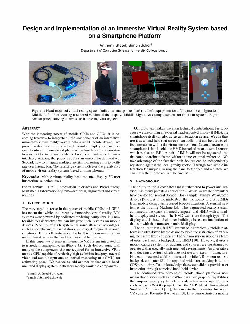
Figure 1: Head-mounted virtual reality system built on a smartphone platform. Left: equipment for a fully mobile configuration.Middle Left: User wearing a tethered version of the display. Middle Right: An example screenshot from our system. Right:Virtual panel showing controls for interacting with objects.
ABSTRACT
With the increasing power of mobile CPUs and GPUs, it is be-coming tractable to integrate all the components of an interactive,immersive virtual reality system onto a small mobile device. Wepresent a demonstration of a head-mounted display system inte-grated onto an iPhone-based platform. In building this demonstra-tion we tackled two main problems. First, how to integrate the user-interface, utilizing the phone itself as an unseen touch interface.Second, how to integrate multiple inertial measuring units to facili-tate user interaction. The resulting system indicates the practicalityof mobile virtual reality systems based on smartphones.
Keywords: Mobile virtual reality, head-mounted display, 3D userinteraction, selection tasks.
Index Terms: H.5.1 [Information Interfaces and Presentation]:Multimedia Information System—Artificial, augmented and virtualrealities
1 INTRODUCTION
The very rapid increase in the power of mobile CPUs and GPUshas meant that while until recently, immersive virtual reality (VR)systems were powered by dedicated rendering computers, it is nowfeasible to ask whether we can integrate such systems on mobiledevices. Mobility of a VR system has some attractive advantages,such as no tethering to base stations and easy deployment in novelsituations. If the VR systems can be built with consumer compo-nents, then it reduces the need for specialist hardware.
In this paper, we present an interactive VR system integrated onto a modern smartphone, an iPhone 4S. Such devices come withmany of the components that are required for an immersive VR: amobile GPU capable of rendering high definition imagery, externalvideo and audio output and an inertial measuring unit (IMU) forestimating pose. We needed to add another tracker and a head-mounted display system; both were readily available components.
∗e-mail: [email protected]†email: [email protected]
Our prototype makes two main technical contributions. First, be-cause we are driving an external head-mounted display (HMD), thesmartphone itself can also act as an interaction device. We can thususe it as a hand-held (but unseen) controller that can be used to ef-fect interaction within the virtual environment. Second, because thesmartphone is hand-held, the HMD is tracked by an external sensor,which is also an IMU. A pair of IMUs will not be registered intothe same coordinate frame without some external reference. Wetake advantage of the fact that both devices can be independentlyregistered against the local gravity vector. Through two simple in-teraction techniques, raising the hand to the face and a clutch, wecan allow the user to realign the two IMUs.
2 BACKGROUND
The ability to use a computer that is untethered to power and ser-vices has many potential applications. While wearable computershave existed for several decades (for example, Mann’s WearCompdevices [9]), it is in the mid-1990s that the ability to drive HMDsfrom mobile computers received broader attention. A seminal sys-tem is the Touring Machine [5]. This augmented reality systemcombined a backpack-mounted computer and HMD with a hand-held display and stylus. The HMD was a see-through type. Thedisplay could show labels over buildings based on interaction ofthe user with the untracked handheld display.
The desire to run a full VR system on a completely mobile plat-form is partly driven by the desire to avoid the restriction of tether-ing the user to fixed equipment. The Virtsim system supports a teamof users each with a backpack and HMD [10]. However, it uses amotion capture system for tracking and so users are constrained tooperate within specially instrumented environments. An alternativeis to develop a system which does not use any fixed infrastructure.Hodgson presented a fully integrated mobile VR system using abackpack computer [8]. It supported wide area tracking based onGPS positioning. To our knowledge the system did not provide userinteraction through a tracked hand-held device.
The continued development of mobile phone platforms nowmeans that devices such as the iPhone 4S have graphics capabilitiesthat surpass desktop systems from only a few years ago. Projectssuch as the FOV2GO project from the MxR lab at University ofSouthern California [1][11], demonstrate their potential for use inVR systems. Recently Basu et al. [3], have demonstrated a mobile
VR system using a phone as a component. Compared to their work,the hardware of our system is simpler and we exploit the phoneitself as an interaction device and control panel.
In related work, a number of demonstrations have been madeof using a mobile device as an interaction device. For example,interacting with a remote display [4].
3 PLATFORM OVERVIEW
3.1 HardwareOur mobile VR system is based on an Apple iPhone 4S. The choiceof this rather than an Android-based platform was governed by theavailability of specific peripherals for the iPhone at the time of con-struction. In particular, we required VGA and HMDI video donglesand support for continuous full-screen output. We have demon-strated support for two HMDs. The first is a Sony Glasstron LDI-D100BE (stereo), with 800× 600 full pixel resolution in each eyeand a horizontal field of view of approximately 28°. This HMD isdesigned to be power by battery or mains. We use a standard iPhoneVGA adapter. This configuration is fully portable. The completeequipment for this setup is shown in Fig. 1, Left. The block at thetop middle of this picture is the HMD control box. The secondHMD is a Sony HMZ–T1. This is a stereo display with 1280×720full pixels in each eye and a horizontal field of view of 45°. It isdesigned to be mains powered, though a portable version could beconstructed. We use a standard iPhone HDMI adapter. We were notable to drive either display in stereo, though it should be possiblewith the Sony HMZ–T1. To track the HMDs, we used the commer-ically available Hillcrest Labs, Freespace Reference Kit, FSRK–BT–1.
3.2 SoftwareThe software was written in a mixture of Objective-C and C++ foriOS 5.0.1 using XCode 4.3.1 and iOS SDK 5.1. We used the ofx-AssimpModelLoader module from OpenFrameworks version 0071
for 3D model loading. Other rendering software was written inOpenGL ES2.0.
The Freespace FSRK–BT–1 communicates using BlueTooth.We investigated several other options for integrating an externaltracker on to the iPhone, including making our own break-out ca-bles, modem-based communication through the microphone, wire-less networks, etc. However all presented problems with the closednature of the hardware and software of the iPhone platform. Blue-Tooth was chosen because various BlueTooth connections had beendemonstrated on jailbroken phones for devices such as wirelesskeyboards and mice. In particular, an open source, portable user-space Bluetooth Stack, btstack, was available 2. With the aid of theHillcrest Lab documentation on the device’s BlueTooth packets wewere able to write a BlueTooth driver that would read the Freespacedevice [7]. Thus to make this prototype the iPhone, running iOS5.0.1, needed to be jailbroken. This may not be necessary in futureversions of iOS that may allow users more freedom in selectingexternal peripherals or if a 3D tracker peripheral manufacturer iscertified by Apple for use with iOS.
4 SMARTPHONE AS UNSEEN TOUCH PANEL
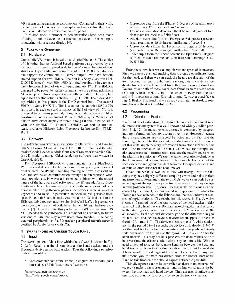
4.1 InputThe overall patten of data flow within the software is shown in Fig.2, Left. Recall that the iPhone acts as the hand tracker, and theFreespace device as the head tracker. Thus the following raw infor-mation is available:
• Accelerometer data from iPhone: 3 degrees of freedom (eachreturned as a 32bit float, meters / second2)
1http://www.openframeworks.cc/2http://code. google.com/p/btstack/
• Gyroscope data from the iPhone: 3 degrees of freedom (eachreturned as a 32bit float, radians / second)
• Estimated orientation data from the iPhone: 3 degrees of free-dom (each returned as a 32bit float)
• Accelerometer data from the Freespace: 3 degrees of freedom(each returned as 16 bit integer, millimeters / second2)
• Gyroscope data from the Freespace: 3 degrees of freedom(each returned as 16 bit integer, milliradians / second)
• Touch input from the iPhone screen: multiple times 2 degreesof freedom (each returned as 32bit float value, in range 0–320by 0–480)
From these raw data we can exploit various types of interaction.First, we can use the head tracking data to create a coordinate framefor the head, and then we can track the head gaze direction of theuser. Second, we can use the hand tracking data to create a coor-dinate frame for the hand, and track the hand pointing direction.We can orient both of these coordinate frame in to the same sense(Y is up, X to the right, -Z in to the screen or away from the userand roll is rotation around Z, pitch around X, yaw around Y, seeFig. 2, Right). The hand tracker already estimates an absolute rota-tion through the iOS CoreMotion API.
4.2 Processing4.2.1 Orientation FusionThe problem of estimating 3D attitude from a self-contained iner-tial measurement system is a well-known and widely-studied prob-lem [6, 2, 12]. In most systems, attitude is computed by integrat-ing rate information from gyroscopes over time. However, becausethese measurements are corrupted by noise and the fact that thesampling rate is finite, this estimate will drift over time. To counter-act this drift, supplementary information from other sensors can beused. The InterSense [6] and XSens [12] devices, for example, ex-ploit accelerometer information to measure the gravity vector whenthe platform is stationary We use the same integration technique asthe Intersense and XSens devices. This module has as input theaccelerometer and gyroscope data from the Freespace devices, andoutputs an orientation for the head tracker.
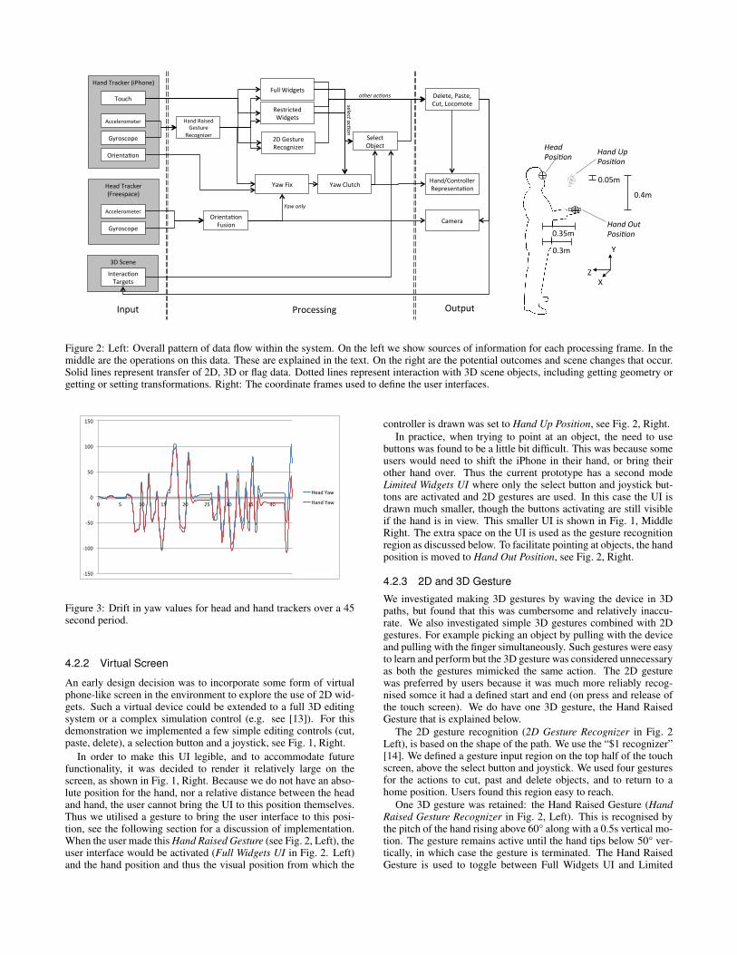
Given that we have two IMUs they will diverge over time be-cause they have slightly different sampling errors and noise in theirmeasurements. Fortunately the two IMUs we use can both be cor-rected against the up (gravity) vector. This means that they divergein yaw (rotation about up) only. To assess the drift which can becaused by movement, we conducted an experiment in which theFreespace was attached to the iPhone, and the two underwent a se-ries of rapid motions. The results are illustrated in Fig. 3, whichshows a 45 second log of the yaw values of the head tracker rigidlyattached to the hand tracker. Both are moved together, and returnedto the starting orientation twice (periods 23–25 seconds and 38–42 seconds). In the second stationary period the difference in yawvalue is 18°s, and the two devices have drifted in opposite directions(head +7°, hand -11°). The devices show some drift while station-ary. In the period 38–42 seconds, the devices drift slowly: 7.3–7.9°for the head tracker (which is consistent with the predicted steadystate covariance of the bias of the gyros), -10.1° – -11.5° for thehand tracker. This may not be a problem for small values of drift,but over time, the offsets could make the system unusable. We thusneed a method to reset the relative heading between the head andhand trackers. Note that in this situation, we do not know if theiPhone would calibrate against the magnetometer, but in any casethe iPhone yaw estimate has drifted from the known start angle.Thus on this timescale we should expect noticeable yaw drift.
This divergence cannot be controlled as there is no external ref-erence to make a measurement to, and no known relationship be-tween the two head and hand device. Thus the user interface musttake into account the divergence between the two yaw values.
3D#Scene##
Hand#Tracker#(iPhone)#
Head#Tracker#(Freespace)#
Accelerometer#
Gyroscope#
Orienta>on#
Accelerometer#
Gyroscope#
Touch#
Orienta>on#Fusion#
Yaw#Fix#
Interac>on#Targets#
Hand#Raised#Gesture#
Recognizer#2D#Gesture#Recognizer#
Full#Widgets#Delete,#Paste,#Cut,#Locomote#
Camera#
Hand/Controller#Representa>on#
Input# Output#Processing#
Yaw#Clutch#
Restricted#Widgets#
Select#Object#
select&ac(on&
other&ac(ons&
Yaw&only&
0.3m%
0.35m%
0.05m%
0.4m%
Y%
X%Z%
Head%Posi*on% Hand%Up%
Posi*on%
Hand%Out%Posi*on%
Figure 2: Left: Overall pattern of data flow within the system. On the left we show sources of information for each processing frame. In themiddle are the operations on this data. These are explained in the text. On the right are the potential outcomes and scene changes that occur.Solid lines represent transfer of 2D, 3D or flag data. Dotted lines represent interaction with 3D scene objects, including getting geometry orgetting or setting transformations. Right: The coordinate frames used to define the user interfaces.
-‐150
-‐100
-‐50
0
50
100
150
0 5 10 15 20 25 30 35 40
Head Yaw
Hand Yaw
Figure 3: Drift in yaw values for head and hand trackers over a 45second period.
4.2.2 Virtual Screen
An early design decision was to incorporate some form of virtualphone-like screen in the environment to explore the use of 2D wid-gets. Such a virtual device could be extended to a full 3D editingsystem or a complex simulation control (e.g. see [13]). For thisdemonstration we implemented a few simple editing controls (cut,paste, delete), a selection button and a joystick, see Fig. 1, Right.
In order to make this UI legible, and to accommodate futurefunctionality, it was decided to render it relatively large on thescreen, as shown in Fig. 1, Right. Because we do not have an abso-lute position for the hand, nor a relative distance between the headand hand, the user cannot bring the UI to this position themselves.Thus we utilised a gesture to bring the user interface to this posi-tion, see the following section for a discussion of implementation.When the user made this Hand Raised Gesture (see Fig. 2, Left), theuser interface would be activated (Full Widgets UI in Fig. 2. Left)and the hand position and thus the visual position from which the
controller is drawn was set to Hand Up Position, see Fig. 2, Right.In practice, when trying to point at an object, the need to use
buttons was found to be a little bit difficult. This was because someusers would need to shift the iPhone in their hand, or bring theirother hand over. Thus the current prototype has a second modeLimited Widgets UI where only the select button and joystick but-tons are activated and 2D gestures are used. In this case the UI isdrawn much smaller, though the buttons activating are still visibleif the hand is in view. This smaller UI is shown in Fig. 1, MiddleRight. The extra space on the UI is used as the gesture recognitionregion as discussed below. To facilitate pointing at objects, the handposition is moved to Hand Out Position, see Fig. 2, Right.
4.2.3 2D and 3D Gesture
We investigated making 3D gestures by waving the device in 3Dpaths, but found that this was cumbersome and relatively inaccu-rate. We also investigated simple 3D gestures combined with 2Dgestures. For example picking an object by pulling with the deviceand pulling with the finger simultaneously. Such gestures were easyto learn and perform but the 3D gesture was considered unnecessaryas both the gestures mimicked the same action. The 2D gesturewas preferred by users because it was much more reliably recog-nised somce it had a defined start and end (on press and release ofthe touch screen). We do have one 3D gesture, the Hand RaisedGesture that is explained below.
The 2D gesture recognition (2D Gesture Recognizer in Fig. 2Left), is based on the shape of the path. We use the “$1 recognizer”[14]. We defined a gesture input region on the top half of the touchscreen, above the select button and joystick. We used four gesturesfor the actions to cut, past and delete objects, and to return to ahome position. Users found this region easy to reach.
One 3D gesture was retained: the Hand Raised Gesture (HandRaised Gesture Recognizer in Fig. 2, Left). This is recognised bythe pitch of the hand rising above 60° along with a 0.5s vertical mo-tion. The gesture remains active until the hand tips below 50° ver-tically, in which case the gesture is terminated. The Hand RaisedGesture is used to toggle between Full Widgets UI and Limited
Widgets UI. It is also used to reorient the hand, see below.
4.2.4 Yaw Fix and Yaw ClutchAs noted in Section 4.2.1 the yaw of the head and hand will divergeover time. We provide two mechanisms to re-align the head andhand. The first is provided by the Yaw Fix module. Whilst theHand Raised Gesture is active, the yaw of the head is used to over-write the yaw of the hand. This has the effect of aligning the FullWidgets UI in front of the head. As the hand is lowered, an offsetis calculated between the current hand and head yaw values, andthis offset is then applied to the received yaw values from the handtracker. This has the effect of realigning the hand yaw to the headyaw as the hand is lowered. We have found this to be intuitive forusers.
The second mechanism is provided by the Yaw Clutch. This istriggered by the select action as described above. When the selectaction is activated, the yaw of the hand is frozen, by calculatingan offset that keeps the hand yaw constant as the hand tracker valuecontinues to vary. This offset is then held constant as select action isdeactivated. This acts as a clutch: hold the button to freeze the handcontroller and reorient your hand. Users also found this intuitive todo.
4.2.5 Object SelectionIn the Limited Widgets UI version, a blue ray is drawn along thepointing direction of the handheld control (-Z), see Fig. 1, MiddleRight. When the select button is pressed a ray is cast along this rayto select an object. This uses a single ray cast and thus allows theprecise selection of small targets. Because the tracking is stable,we have not seen a need for the user to press select and then “hunt”for the target on release. We have found that the Yaw Clutch andselect action can be activated by the same button: a select is a click,whereas a hold is the clutch. Users pick up the dual use quickly andhave not reported this to be a problem.
4.3 OutputOne module performs edits (cut, paste, delete) on the scene. Loco-motion about the environment is effected using the virtual joystickthat appears on both the Full Widgets UI and Limited Widgets UI.Because we are using the head direction as the principle direction,and correcting the hand orientation to that as described above, weuse the locomotion direction based on travelling forwards and back-wards in the direction of gaze. The vertical distance from the initialpress event on the virtual joystick is used as velocity of travel. Thereis a dead zone, and a maximum distance: the range (10,50) pixelsdistance is mapped to (0, 2) m/s. The horizontal distance is simi-larly mapped: (10,50) to (0, 90) degree/s rotation in yaw around thehead position.
5 CONCLUSION
In this technote, we have described the development of a HMD-based VR system that is integrated onto an iPhone-based platform.The design of the system is novel in that it exploits the iPhone itselfas an unseen touch controller. The main difficulty in implementa-tion was the lack of registration between the two IMUs: one in theiPhone and a separate one on the head. Given that there we no exter-nal reference signals to utilize, the user interface had to be adaptedas discrepancies in yaw between the two sensor could rapidly growto the point where pointing behaviour is unacceptably degraded. Toovercome these limitations, we introduced two mechanisms: a ges-ture to automatically realign the coordinate systems crudely, and aclutch to manually realign them precisely. The system can oper-ate at 60Hz for worlds with a few thousand polygons. Latency isacceptable at approximately 100ms.
We have evaluated this system informally with various demon-strations and also in a pilot trial that demonstrated that the clutch
technique was easy to learn and useful to the users. Overall usersfound the system easy to use. None had problems navigating aboutthe environment and interacting with objects.
There are many potential future avenues of work. Aside fromintegrating the constantly improving hardware, we believe that oneof the most fruitful areas of further consideration will be to exploreother characteristics of behaviours that can be used to effect regis-tration between different sensors.
Finally, we hope that the availability of an immersive VR systemthat is based on a widely available consumer platform and otherreadily available components, may enable new applications of VRin domains where installation and maintenance costs might other-wise be an issue.
ACKNOWLEDGEMENTS
This work was funded through the European Commission for theEuropean Union project BEAMING (FP7-248620).
REFERENCES
[1] Fov2go project. http://projects.ict.usc.edu/mxr/diy/fov2go/, Dec. 2012.
[2] R. Azuma. Predictive Tracking for Augmented Reality. PhD thesis,UNC Chapel Hill, 1995.
[3] A. Basu, C. Saupe, E. Refour, A. Raij, and K. Johnsen. Immersive3dui on one dollar a day. In 3D User Interfaces (3DUI), 2012 IEEESymposium on, pages 97 –100. IEEE Computer Society, 2012.
[4] R. Dachselt and R. Buchholz. Natural throw and tilt interaction be-tween mobile phones and distant displays. In Proceedings of the 27thinternational conference extended abstracts on Human factors in com-puting systems, pages 3253–3258. ACM, 2009.
[5] S. Feiner, B. MacIntyre, T. Hollerer, and A. Webster. A touring ma-chine: Prototyping 3d mobile augmented reality systems for exploringthe urban environment. In Proceedings of the 1st IEEE InternationalSymposium on Wearable Computers, ISWC ’97, pages 74–81. IEEEComputer Society, 1997.
[6] E. Foxlin. Inertial Head-Tracker Sensor Fusion by a ComplementarySeparate-Bias Kalman Filter. In Proceedings of IEEE Virtual Real-ity Annual Symposium VRAIS ’96, pages 185–194. IEEE ComputerSociety, 1996.
[7] Hillcrest Labs. Freespace hid report definitions. http://libfreespace.hillcrestlabs.com/libfreespace/1000-2045-HIDReportDefinitionsv1.0.pdf, Dec. 2012.
[8] E. Hodgson, E. Bachmann, D. Waller, A. Bair, and A. Oberlin. Vir-tual reality in the wild: A self-contained and wearable simulation sys-tem. Proceedings of IEEE Virtual Reality Conference, pages 157–158,2012.
[9] S. Mann. An historical account of the ’wearcomp’ and ’wearcam’inventions developed for applications in ’personal imaging’. In Pro-ceedings of the 1st IEEE International Symposium on Wearable Com-puters, pages 66–73. IEEE Computer Society, 1997.
[10] Motion Reality Inc. Virtsim. http://www.motionrealityinc.com/, Dec. 2012.
[11] L. Olson, D. M. Krum, E. Suma, and M. Bolas. A design for asmartphone-based head mounted display. In IEEE Virtual Reality,pages 233–234, Singapore, Mar. 2011. IEEE.
[12] D. Roetenberg, H. Luinge, and P. Veltink. Inertial and magnetic sens-ing of human movement near ferromagnetic materials. In Proceed-ings of the 2nd IEEE/ACM International Symposium on Mixed andAugmented Reality, pages 268–. IEEE Computer Society, 2003.
[13] Z. Szalavari and M. Gervautz. The personal interaction panel: A two-handed interface for augmented reality. Computer Graphics Forum,16(3):335–346, 1997.
[14] J. O. Wobbrock, A. D. Wilson, and Y. Li. Gestures without libraries,toolkits or training: a $1 recognizer for user interface prototypes. InProceedings of the 20th annual ACM symposium on User interfacesoftware and technology, pages 159–168. ACM, 2007.