design and implementation of an “approximate†communication system for wireless media
TRANSCRIPT

Design and Implementation of an “Approximate”Communication System for Wireless Media Applications
Sayandeep Sen#, Syed Gilani$, Shreesha Srinath$, Stephen Schmitt$ and Suman Banerjee#
University of Wisconsin-Madison{sdsen,suman}@cs.wisc.edu#, {gilani,ssrinath,sschmitt1}@wisc.edu$
ABSTRACTAll practical wireless communication systems are prone to errors.At the symbol level such wireless errors have a well-defined struc-ture: when a receiver decodes a symbol erroneously, it is morelikely that the decoded symbol is a good “approximation” of thetransmitted symbol than a randomly chosen symbol among all pos-sible transmitted symbols. Based on this property, we define ap-proximate communication, a method that exploits this error struc-ture to natively provide unequal error protection to data bits. Un-like traditional (FEC-based) mechanisms of unequal error protec-tion that consumes additional network and spectrum resources toencode redundant data, the approximate communication techniqueachieves this property at the PHY layer without consuming anyadditional network or spectrum resources (apart from a minimalsignaling overhead) . Approximate communication is particularlyuseful to media delivery applications that can benefit significantlyfrom unequal error protection of data bits. We show the usefulnessof this method to such applications by designing and implement-ing an end-to-end media delivery system, called Apex. Our Soft-ware Defined Radio (SDR)-based experiments reveal that Apex canimprove video quality by 5 to 20 dB (PSNR) across a diverse setof wireless conditions, when compared to traditional approaches.We believe that mechanisms such as Apex can be a cornerstone indesigning future wireless media delivery systems under any error-prone channel condition.
Categories and Subject DescriptorsC.2.1 [Computer Communication Networks]: Network Archi-tecture and Design—Wireless Communication
General TermsAlgorithms, Design, Experimentation, Measurement, Performance
KeywordsCross layer, Media Delivery, Wireless PHY
Permission to make digital or hard copies of all or part of this work forpersonal or classroom use is granted without fee provided that copies arenot made or distributed for profit or commercial advantage and that copiesbear this notice and the full citation on the first page. To copy otherwise, torepublish, to post on servers or to redistribute to lists, requires prior specificpermission and/or a fee.SIGCOMM’10, August 30–September 3, 2010, New Delhi, India.Copyright 2010 ACM 978-1-4503-0201-2/10/08 ...$10.00.
1. INTRODUCTIONAny communication system, whether wired or wireless, is im-
pacted by errors. Typically, a transmitter encodes application datain a frame as a set of symbols, where each symbol encodes one ormore data bits. When errors happen, one or more of these symbolsare incorrectly decoded at the receiver, leading to loss in perfor-mance.
Conventional design of networked systems have assumed thatcommunication channels are error-prone and handle them in vari-ous ways. Often a checksum field is added to each data unit. Areceiver verifies the received checksum against the expected check-sum for the data bits to validate correct reception. Higher layersdeal with these errors in different ways.
At the MAC layer, some protocols (such as 802.11) typicallydiscard packets received with checksum errors. A newer class ofMAC-PHY mechanisms attempt to recover correct bits from pack-ets with partial errors. Examples include partial packet recovery(PPR) [18], SOFT [36], ZipTx [21], and Maranello [13]. Similarly,at the transport layer TCP would re-transmit erroneous or lost seg-ments. UDP simply discards them silently. UDP-lite delivers er-roneous packets to applications, and allows applications to recovercorrect portions of these packets using partial checksums.
In all the above techniques, it is the job of the receiver to de-termine and discard erroneous bits within a packet, and the trans-mitter has no a-priori knowledge of which bits (or bit positions)are likely to be in error. In this paper, we demonstrate an alternatepossibility — At the PHY layer, there is a systematic structure towireless errors, and a wireless transmitter can leverage this struc-ture to ensure that certain bit positions are less likely to be in errorthan other bit positions. If the transmitter is aware of relative im-portance of data bits, it can place more important data bits in moreprotected positions and the less important data bits in less impor-tant positions. In other words, a transmitter can ensure an unequalerror protection (UEP) of its data by simply placing data bits inspecific bit positions. Thus, unlike prior approaches of UEP thatexplicitly need to add redundant bits to higher priority data [24, 35,15], this proposed approach would not require any redundant databits to be transmitted to achieve UEP, and is available natively fromthe wireless channel (apart from minimal signaling overhead).
Further, adaptation of the relative degree of UEP available todifferent bit-positions can be done based on application needs andambient channel condition.
The relevant error structure across the wireless channel is a con-sequence of the following phenomenon: When a wireless symbolis decoded in error, this erroneous symbol is still a good “approx-imation” of the original transmitted symbol. (We will make thisnotion more precise in the next section.) Based on this approxi-mation property, we design a wireless communication method to
15

provide UEP that we call, approximate communication. Approxi-mate communication can provide significant performance gains toall applications in which different data bits have different levels ofpriority, e.g., the I-, P-, and B-frame structure in MPEG-4-AVC [3]encoded video. In particular, we design and implement a specificapproximate communication system called Apex (an Approximatecommunication system for media exchange) that combines knowl-edge of relative bit priorities of the application with the structure ofwireless errors and client feedback on channel conditions to achieveimproved performance for media applications.
Apex requires a few, albeit marginal, modifications to the radiotransmit-receive paths. These modifications include a few addi-tional buffers, multiplexers, and a little amount of additional ad-dressing logic. The latencies due to such additional data process-ing is negligible. Through detailed experiments on the WARP SDRplatform [6] under various interference and multi-path scenarios,we demonstrate how Apex can improve the quality of video deliv-ered over a wireless link, using a mechanism that is complementaryto existing approaches.
Key contributions: We summarize the above discussion by iden-tifying the main contributions of our work:
• Apex, an approximate communication system to improve ap-plications: We show that wireless errors have a well-definedstructure at the PHY layer. This structure allows the wirelessPHY layer to natively provide UEP to data bits, which formthe foundation of approximate communication.
Further, we show that by suitably adapting system parame-ters, based on current channel conditions and application re-quirements Apex significantly improves performance of ap-plications that prioritize different data bits differently.
• Design of modifications to transmit-receive paths of an 802.11radio to support approximate communication in Apex: Apexrequires minor modifications to the transmit-receive pathsof a wireless radio. We describe how the transmit-receivechains of present day 802.11 hardware should be modifiedto implement approximate communication. We demonstratesuch modifications can co-exist with other complementarymechanisms implemented in the lower layers, such as a scram-bler system, convolution coding, data interleaving, data mod-ulation, and PHY transmission rate selection.
• Implementation of the Apex-based video delivery system: Wedemonstrate that Apex can be practically implemented bybuilding a prototype system using the WARP Software De-fined Radio (SDR) hardware and running H.264 video streamsthrough them over the air.
• Experimentation over range of scenarios: We show that Apexcan, indeed, provide significant performance gains for mediaapplications over a range of wireless communication scenar-ios. In different experiments, we varied the transmit powerlevels, the position of nodes, and the degree of external inter-ference to demonstrate the robustness of our schemes. Overvarious experiment scenarios, it provided a video quality im-provement of 5-20 dB(measured in terms of PSNR).
The fact that wireless symbol errors of popular modulation schemeshave a specific error structure has both been analytically studied byresearchers [23, 2, 38, 8] and experimentally demonstrated [30].However, many popular wireless communication standards, e.g.,IEEE 802.11, consider such a structure to be a nuisance. In fact,standards such as IEEE 802.11 typically employ a set of random-ization and data protection mechanisms, (convolution coding, data
010 011 111 101
Originalimage
Data bits
Tx symbols Rx symbols
Received bits011 011 111 110
Receivedimage
Figure 1: High level overview of wireless communication.(Some MAC layer operations, e.g., coding, scrambling, and in-terleaving are not shown.)
scrambling, and data interleaving) to ensure that all application bitsare equally likely to be in error. These data randomization mecha-nisms have a number of other advantages. Hence, their wide adop-tion and specific placement in the protocol stack ensured that op-portunities of natively providing UEP on the wireless channel waslost.
In this work we explain how the wireless symbol error structurecan be leveraged to implement UEP in approximate communica-tion (Sections 2 ), how it can be practically implemented in Apex(Section 3) to co-exist with the popular data randomization and pro-tection techniques (convolution coding, data scrambling, and datainterleaving) and how relevant parameters like modulation schemeand constellation mappings can be dynamically adapted (Section 3)to improve the quality of media delivered.
We believe that approximate communication can offer a usefuldesign alternative for wireless media delivery systems and facilitategreater interaction between characteristics observable at the PHYlayer and expectations of the applications.
2. INTUITION AND APPROACH FOR AP-PROXIMATE COMMUNICATION
Figure 1 shows a high level (and somewhat simplified) schematicof data transfer across a wireless link as it happens for commontechnologies today. Let us assume that the content is encoded intoa data bit sequence using a popular format, e.g., MPEG-4 [3]. Af-ter packetization, the transmitter of the wireless link maps thesebits into symbols for transmission across the wireless channel. Inour example, each symbol represents a set of three data bits. Thereceiver attempts to infer the transmitted symbols, but sometimesmakes decoding errors. Hence, when the received symbols aremapped back into a bit sequence, bit errors might result (erroneousbits and symbols are shaded). An important thing to note is thatwhen a symbol error occurs, not all its constituent bits are actu-ally in error. Symbol errors in common wireless technologies,e.g., those based on the popular I/Q modulation schemes, have avery well defined structure. When a receiver decodes a symbolerroneously, it is more likely that the decoded symbol is a good“approximation” of the transmitted symbol, than a randomly cho-sen symbol among all possible symbols. In this section, we explainthis phenomenon through an example based on Quadrature Ampli-tude Modulation (QAM) 1.
In QAM, data elements are encoded into amplitude values oftwo sinusoidal waves that are 90 degrees out-of-phase with eachother. A QAM modulation scheme is usually represented by a I/Qconstellation diagram, as shown in Figure 2. Each constellationpoint (or symbol) is mapped to the amplitude of the in-phased andthe quadrature-phased signals, and corresponds to a certain bit se-quence to be transmitted. In a 256-QAM scheme (shown in Fig-
1Some of the different mechanisms manipulated in the paper mightappear similar in meaning. Hence, for the sake of clarity, we definethe use of our terms and their meaning in Table 1.
16

Term Meaning / ExamplesModulation scheme 16-QAM, 64-QAM, etc.Constellation map Mapping from bit-sequence
to symbols (Gray, Block, etc.)Data bit Mapping of data bits toplacement bit positions in symbols
Table 1: Table summarizing some terminology used for differ-ent mechanisms used in the paper.
(a) 256 QAM (b) 64 QAM (c) 16 QAM
CA B D E X
Figure 2: Quadrature Amplitude Modulation (QAM) constel-lations.
ure 2(a)), there are 256 distinct symbols. Each such symbol en-codes a 8-bit sequence of data to be transmitted. In contrast, in a64-QAM scheme, there are 64 distinct symbols, and each symbolencodes a 6-bit data sequence (Figure 2(b)). When a transmitterwants to communicate a specific bit-sequence, it emits the corre-sponding symbol. The goal of the receiver is to identify whichsymbol was sent.
Let us consider the case of a transmitter-receiver pair using 64-QAM and the transmitter emits a symbol, say C (Figure 2(b)).Depending on the conditions of the channel, there is a reasonablechance that the receiver will correctly decode this symbol. How-ever, there is also some possibility for the receiver to make an errorin decoding this symbol. It turns out that if an error does occur,such errors are most likely confined to the near neighborhood ofthe transmitted symbol C, i.e., the receiver is more likely to de-code this symbol to be one of A, B, D, or E, which are the nearestneighbors of C (indicated by the inner circle of Figure 2(b)), ascompared to a far away symbol, X . In other words, within the 2-dimensional I/Q space, an erroneously decoded symbol tends to bea reasonable approximation of the transmitted symbol.
As noise in the environment increases, the likelihood of makingincorrect decoding decisions to “faraway” symbols can increase tosome extent (as indicated by the larger circle in Figure 2(b)). How-ever, likelihood of making errors within close proximity also in-creases, and continues to significantly dominate such faraway er-rors. We illustrate this behavior in Figure 3 in which 10 million64-QAM symbols were transmitted between a transmitter-receiverpair under two different conditions, ambient noise, and explicitlygenerated interference in the background. The Y-axis representsthe probability that the transmitted symbol is decoded erroneouslyto be another symbol at a distance given in the X-axis. The loga-rithmic scale of the Y-axis demonstrates the dramatic decay in thisprobability with increasing distance between the transmitted anddecoded symbols.
Further, if the noise conditions continue to increase in this man-ner, a reasonable communication system will adjust to a lower ratemodulation scheme, such as 16-QAM (Figure 2(b)), which sepa-rates constellation points further apart. This allows the system torevert back to the original scenario where erroneous symbols aremostly the nearest neighbors of the transmitted symbol.
10-6
10-5
10-4
10-3
10-2
1 1.5 2 2.5 3 3.5 4Err
or p
roba
bilit
y (in
logs
cale
)
Euclidean distance
with interferencewithout interference
Figure 3: Fast decay in probability of erroneous decoding asthe distance between the correct symbol and the erroneouslydecoded symbol increases. Data based on 10 million known 64-QAM symbols transmitted. In the ambient noise scenario, theoverall BER was 3×10⁻⁴. In the explicit interference scenario,the overall BER was 6 × 10⁻³.
2.1 UEP and approximate communicationThe wireless error structure demonstrated in Figure 3 leads to a
construction of UEP for data bits. This is achieved by appropriatelychoosing a constellation map, i.e., the map between bit-sequencesand symbols in a constellation diagram.
For the sake of simplicity, let us assume that when symbol errorsoccur, the erroneous symbol is just one unit away from the actualtransmitted symbol. In the 64-QAM example in Figure 2(b), thisassumption implies that when C is transmitted, a decoding errorwould result in the received symbol to be one among A, B, D, andE.
Now imagine if a constellation map was to map bit-sequencesrandomly to symbol positions. Then, when an error occurs, thelikelihood of a correct value in any given bit position is purely bychance. The probability of such an event is 0.5, i.e., the probabilitythat a neighboring symbol has the same most significant bit (MSB)value as the MSB of the actually transmitted symbol is 0.5, andthe same is true for the least significant bit (LSB) and all other bitpositions in between. Such a constellation map does not help inachieving our desired goal in approximate communication.
Fortunately, various common constellation maps, e.g., the Graycode (used in 802.11 ) map bit sequences to symbols in a way thatincreases the resilience of certain bits, even when the symbols arein error. As an example, the Gray code corresponding to a 16-QAM constellation is shown in Figure 4. If we examine the MSBof the different symbols to the left of the Q-axis, we can observethat all of them have a value of 0. Similarly, the MSB of differentsymbols to the right of Q-axis all have a value of 1. In such a case,if a decoding error occurs for any symbol within the shaded region,there are no errors in the MSB (under our assumption that symbolerrors do not exceed 1 unit). For the remaining symbols, we expectan error probability of either 1/4 or 1/3 for the MSB, dependingon its position in the constellation. If the likelihood of transmittingeach symbol is identical, then the probability of error in the MSB,given a symbol error has occurred, is 1/6. For the LSB, on the otherhand, the probability of making an error, given a symbol error hasoccurred, is 1/3. This gives rise to an intriguing possibility. If anapplication identifies different priority levels for its various databits, then instead of performing data bit placement (mapping thesedata bits to bit positions in symbols) in an agnostic manner, we canachieve the desired impact of differential data protection by placingthe higher priority data bits to the MSB positions of symbols, andthe lower priority data bits to the LSB (and other) positions.
Note that such differential protection of data values is possible by
17

0000 0100 1100 1000
0001 0101 1101 1001
0011 0111 1111 1011
0010 0110 1110 1010
_ _ _ _ _ _ _ _
_ _ _ _ _ _ _ _
_ _ _ _ _ _ _ _
_ _ _ _ _ _ _ _
M
N
X
Z
Y
P
Figure 4: 16-QAM with Graycode constellation map. MSBsand LSBs are underlined.
0 1 0 01 1 0 10 0 1 01 0 0 1I-frameI-frame P-frameB-frame
X = 0 1 0 0Z = 1 1 0 1Y = 0 0 1 0P = 1 0 0 1
Wireless packets (exactly mapped from video frames)Traditional communication
0 1 0 01 1 0 10 0 1 01 0 0 1I-frameI-frame P-frameB-frame
M = 0 1 1 1N = 0 0 0 1Y = 0 0 1 0P = 1 0 0 1
Wireless packets (combines bits from differentvideo frames)
Approximate communication
Figure 5: Wireless frames in approximate communication combines bits from videoframes of different priority levels. Example uses 16-QAM and assumes that the twoMSBs can be better protected than the two LSBs. The data bit placement strategymaps I-bits MSBs and P- and B-bits to LSBs. Symbols M, N, P, X, Y , and Z are asshown in Figure 4 that uses a Gray code constellation map. (Only subset of data bitplacements shown.)
simply placing the data bits to appropriate bit positions, and withoutadding any form of redundancy into the system. In a way, suchdata protection is available natively through the wireless channel,and can be better exploited by applications, without imposing anyoverheads. This is in contrast to the traditional FEC-based methodsfor providing UEP that require communication of additional bitsthat redundantly encode more important data.
Also, while we explained the phenomenon of differential errorresilience of bit positions with the example of QAM modulationthe same would hold for other modulation schemes such as PhaseShift Keying(PSK), Pulse Position Modulation (PPM), FrequencyShift Keying (FSK) etc. as well.
Based on the above intuition, we build an approximate commu-nication system that can provide differential protection to differentdata bits of an application. We use streaming of MPEG-4 encodedvideo as an example of such an application. Such a video streamconsists of frames with different levels of importance, e.g., I-framesare more important than P-frames, which in turn are more impor-tant than B-frames.
Akin to regular communication systems, the application createsand continuously sends data bits corresponding to different frames(I, P, and B) down the network protocol stack. Bits from each videoframe will be packetized in smaller chunks at the network and MAClayers, and then will be handed into the digital component of thePHY layer. This is shown in Figure 5, with four video frames —two I-frames with data 0100 and 0010, a P-frame with data 1101,and B-frame with data 1001. In traditional communication sys-tems, the 4-bit sequences of each frame gets placed together in asingle wireless frame, e.g., the first I-frame is mapped to the firstwireless frame (consisting of a single symbol X). The key differ-ence in approximate communication is that data bits of differentpriority levels will be placed together and combined into a singlesymbol, such that the most protected bit positions are occupied bythe higher priority data bits (say, I bits), and the least protected bitpositions are occupied by the lower priority data bits (say, P and Bbits). For example, the first two bits of the first I-frame, i.e., 01,are mapped to MSBs of the first symbol of a wireless frame, whilethe second two bits of the same I-frame, i.e., 00, are mapped tothe MSBs of the symbol of the next frame 2. The bits of P- andB-frames are placed into the LSB positions of different symbols.
2In our actual implementation, the I-, P-, and B-frame bits wouldfirst go through the usual 802.11-style digital PHY processes, in-cluding the scrambler, convolution coder, and the interleaver foradded resilience, before being mapped to the symbols.
Overall, this means the I-frame bits will be better protected thanthe P- and B-frame bits.
When symbols are decoded (possibly in error), the receiver sim-ply passes them along to the higher layers, even if in error. Whenthe different application bits are extracted out of these erroneoussymbols, the highest priority bits are most likely to be correct andare of great value to the application. Lower priority ones maybe inerror and will be suitably handled. The key observation is that thehigher priority bits are, thus, successfully extracted out of the sym-bols, even if in error, through this mechanism, without requiringre-transmissions.
This differential protection is in contrast to the traditional com-munication method used in 802.11a/b/g, where I-frame bits occupyboth MSB and LSB positions of a symbol, the same as P- and B-frame bits, and there is no difference in the level of protection forbits of different video frames.
To validate that our approach of approximate communication is,indeed, possible, we need to identify one or more constellationmaps that provide unequal error protection among different bit po-sitions, across a range of wireless conditions — different transmitpower levels, different degrees of interference at the receiver, andwith and without PHY layer convolutional codes. Such confirma-tion of unequal protection will provide further evidence that ourapproximation property holds true for a range of common scenar-ios, where approaches such as Apex can be quite worthwhile.
Given a constellation diagram of k points, each symbol will rep-resent a bit-sequence of length log2(k) bits. Overall, there are nomore than k! different constellation maps possible, although someof them can be identical due to rotation and reflection based sym-metries. Each constellation map is likely to protect individual bitpositions differently. The above property can be leveraged by al-tering the constellation map during an ongoing transmission, basedon the channel conditions and the relative priority of the applicationdata-bits.
In this section, we present results for two constellation maps,each of which offer varying amount of error protection for differentbit positions.
Both are, therefore, suited for approximate communication. Wenote that our contribution is not in designing these constellationmaps, but in identifying suitable ones and in exploiting them to im-plement approximate communication for media applications. Wefirst briefly describe the schemes, and then evaluate their error pro-tection properties in the rest of this section.
18

Modulation schemes 16 and 64 QAMEncoding schemes Gray, BlockFrequency 2.4 GHzConvolutional codes Generator polynomials: g0(133)(when used) g1(171), Rate = 1/2, 2/3, 3/4Base data rate 485 Kbps (at rate 1/2)
Table 2: Properties of our implemented system.
TransmitterInterferer
WARPradio
Laptop
Receiver
Figure 6: Setup for communication between the two WARPSDR radios. The relative position, transmit power levels, anddegree of external interference varied during different experi-ments.
2.2 Example constellation mapsWe evaluate the following two constellation maps for use in ap-
proximate communication.Gray code: In Gray code [12], symbols that are immediate neigh-
bors either along the I-axis or the Q-axis of the I/Q space differ inexactly one bit position; the rest of the bits are identical betweenthe two neighbors. An example of a Gray code is shown in Fig-ure 4, for a 16-QAM system. Gray codes can be constructed for anyQAM scheme in a systematic manner based on the above observa-tion. Gray code is widely used in many popular communicationsystems, including in 802.11 a/g/n and 802.16 based systems.
Block code: In block code [23], the constellation points on thesame side of the I (Q) axis have the same value for the first (sec-ond) bit position. Hence, all points in a given I-Q quadrant havethe same value for the first two bit positions. For each of thesequadrants, the symbols are partitioned into four sub-quadrants, andthe same process is repeated to assign bit values for the next twobit positions. The process is repeated iteratively for the remainingpositions.
Both of these schemes can be implemented on different QAMbased modulation schemes. While we have implemented and ex-perimented with different QAM schemes in our SDR radio plat-form, for sake of uniform comparison, in this section we focus onthe 64-QAM scheme. In 64-QAM, each symbol encodes 6-bit se-quences, and in diverse experiments we observe how the differentschemes differentially protect the two most significant bits (MSBs),the two middle bits (MID), and the two least significant bis (LSBs).
2.3 Experiment configurationsWe use the following experiment parameters.
Hardware and software: We implemented our system on the WARPSDR radio platform [6]. In our implementation we used the WARPboards as RF front-end to transmit the packets over air and carriedout the digital layer PHY signal processing activities in the con-nected laptop. The laptops also acted as the traffic source and sink.The setup for our experiments is depicted in Figure 6. We summa-rize various aspects of our implementation in Table 2.Frequency and phase synchronization between the sending and re-
ceiving side was achieved using a 11 symbol barker sequence sentas a preamble along the packet. We experimented by varying thetransmit power levels of the transmitter, adding external source ofinterference and by changing the location of the nodes. The re-ceiver sensitivity of WARP hardware in our implementation is -70dBm for 64-QAM and at lower RSSI values (< -70 dBm) 3 it be-comes difficult to derive any meaningful results. Hence, for all oftransmit power variations, we report on RSSI values that varied be-tween -30 and -70 dBm.Metrics: In this section, we are interested in the relative bit errorrates (BERs) experienced by different bit positions of a symbol.Hence, we compare the two constellation maps by examining theBERs of the MSBs, MIDs, and LSBs across different conditions.In certain plots, we report BER gain which is the ratio of the BERof Block code to that of Gray code, for specific bit positions. BERgain can, thus, be a number greater than 1.Experiment parameters: In each experiment we sent 10 millionrandomly generated symbols. For each symbol received, we de-code its value using both maps, and calculate the error rates fordifferent bit positions.
A typical 802.11 PHY layer (optionally) applies convolution code(a PHY layer FEC) to further protect the data-bits. In order to eval-uate the effect of such PHY layer convolution codes, we have alsoexperimented with (and without) different convolution codes (ratesinclude 1/2, 2/3, and 3/4) as well. Our results show that unequalerror protection property holds both with and without convolutioncodes. In this paper, we show the error resilience of different bitpositions in presence of PHY layer convolution coding only for aconvolution code of rate 1/2.
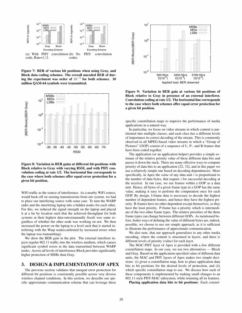
2.4 Experimental resultsWe describe our experiments and associated observations below.With and without PHY convolution codes: We plot the error
rate at the MSBs, MIDs, and LSBs for the two constellation maps atan intermediate transmit power level (RSSI -55 dBm) in Figure 7,both with and without PHY convolution codes. Each constellationmap provides different levels of protection to these bit positions.In both cases, Block provides the greatest error protection to theMSBs at the cost of lower protection to the LSBs. The use of con-volution codes clearly reduce the BERs suitably, but the effect ofunequal error protection exists both with and without use of convo-lution codes. Hence, in the rest of this paper, we focus on resultswith PHY convolution codes applied.
Ambient noise, varied transmit power levels, with PHY con-volution codes: We present the performance of the Gray and Blockconstellation maps for an entire range of received power (varied bychanging the transmit power levels as well as the separation be-tween nodes and their locations), when using a convolution rate of1/2 in Figure 8. Instead of the BER, we plot the BER gain. Withdecreasing RSSI, symbol errors increase. As a consequence, theBER of Block shrink in comparison to BER of Gray for MSBs,i.e., Block protects MSBs even better compared to Gray as RSSIdecreases. For the range of operating parameters the relativelygreater protection of MSBs using Block changes from a factor of2 (at -30 dBm) to a factor 15(at -70 dBm). The increased protec-tion of MSBs comes at a cost of decreased protection for MIDs andLSBs in Block.Varied external interference: We next examine the behavior ofdifferent encoding schemes in presence of an explicit source ofexternal interference (Figure 9). We had used a laptop sending
3We calculate the RSSI values by reading the MAX2829 ADC out-put register value and mapping it to corresponding RSSI value fromthe Data-sheet [7].
19
10-6
10-5
10-4
10-3
BlockGray
BE
R (
in lo
gsca
le)
Encoding Scheme
MSBsMIDsLSBs
(a) With PHY convolutioncode, Rate=1/2.
10-5
10-4
10-3
10-2
BlockGray
BE
R (
in lo
gsca
le)
Encoding Scheme
MSBsMIDsLSBs
(b) No PHY convolutioncodes.
Figure 7: BER of various bit positions when using Gray, andBlock data coding schemes. The overall uncoded BER of dur-ing the experiment was order of 10−3 for both schemes. 10million QAM-64 symbols were transmitted.
10-2
10-1
100
101
-70-65-60-55-50-45-40-35-30
(BE
R B
lock
)/(B
ER
Gra
y)
RSSI
MSBsMIDsLSBs
Figure 8: Variation in BER gains at different bit-positions withBlock relative to Gray with varying RSSI, and with PHY con-volution coding at rate 1/2. The horizontal line corresponds tothe case where both schemes offer equal error protection for agiven bit position.
WiFi traffic as the source of interference. As a nearby WiFi source,would back-off on sensing transmissions from our system, we hadto place our interfering source with some care. To turn the WARPradio and the interfering laptop into a hidden nodes for each other.For this, we reduced the signal strength on the laptop and placedit at a far by location such that the achieved throughput for bothsystems at their highest data-rates(manually fixed) was same re-gardless of whether the other node was working on not. We thenincreased the power on the laptop to a level such that it started in-terfering with the Warp node(confirmed by increased errors whenthe laptop was transmitting).
We show the BER gain in the plot. The external interferer in-jects regular 802.11 traffic into the wireless medium, which causessignificant symbol errors in the data transmitted between WARPnodes. Across all levels of interference Block provides significantlyhigher protection of MSBs than Gray.
3. DESIGN & IMPLEMENTATION OF APEXThe previous section validates that unequal error protection for
different bit positions is consistently possible across very diversewireless channel conditions. In this section, we describe our spe-cific approximate communication scheme that can leverage these
10-2
10-1
100
101
5760 Kb/sO(10-2)
3450 Kb/sO(10-3)
500 Kb/s O(10-4)
(BE
R B
lock
)/(B
ER
Gra
y)
Applied load, BER observed
MSBsMIDsLSBs
Figure 9: Variation in BER gain at various bit positions ofBlock relative to Gray in presence of an external interferer.Convolution coding at rate 1/2. The horizontal line correspondsto the case where both schemes offer equal error protection fora given bit position.
specific constellation maps to improve the performance of mediaapplications in a natural way.
In particular, we focus on video streams in which content is par-titioned into multiple classes, and each class has a different levelsof importance in correct decoding of the stream. This is commonlyobserved in all MPEG-based video streams in which a “Group ofPictures” (GOP) consist of a sequence of I-, P-, and B-frames thathave been coded together.
The application (or an application helper) provides a simple es-timate of the relative priority value of these different data bits andpasses it down the stack. There are many effective ways to computepriority of data bits to an application [22, 32], and in this paper weuse a relatively simple one based on decoding dependencies. Morespecifically, in Apex the value of any data unit i is proportional tothe number of data bytes, that require i for successful decoding atthe receiver. In our case, we use frames within a GOP as a dataunit. Hence, all bytes of a given frame type in a GOP has the samevalue, making it easy to perform the computation once for eachGOP. By design, I-frame data is necessary to decode the highestnumber of dependent frames, and hence they have the highest pri-ority. B-frames have no other dependent except themselves, so theyhave the least priority. P-frame has a priority which is intermedi-ate of the two other frame types. The relative priorities of the threeframe types can change between different GOPs. As mentioned be-fore, better ways of defining the value of different bytes are, indeed,possible, we choose to use our simple approach, as it is sufficientto illustrate the performance of approximate communication.
We also note, that our approach generalizes to any other mediaencoding, where the content is structured in layers, and there isdifferent levels of priority (value) for each layer.
The MAC-PHY layer of Apex is provided with a few differentconstellation maps. In our case, we use two alternatives — Blockand Gray. Based on the application-specified value of different dataunits, the MAC and PHY layers of Apex makes two simple deci-sions: (i) given a constellation map, how to place application databits to bit positions for the desired levels of protection, and (ii)which specific constellation map to use. We discuss how each ofthese components is implemented by making small changes to an802.11-style PHY-MAC subsystem, while retaining all its features.
Placing application data bits to bit positions: Each constel-
20

lation map provides varying degree of protection for different bitpositions of a symbol. However, once a constellation map has beenchosen, there is only one optimal way to place application data bitsto various protection levels to maximize value of protected data —greedily. Given x data bits across all priority levels, and m bits persymbol, the total number of symbols available is x/m. We startby placing the highest priority bits to the most protected bit posi-tions of each of these symbols. We move over to the next protectedbit positions, if we exhaust the most protected bit positions. Oncewe complete assigning all highest priority bits, we move to bitsat the next priority level. We continue until we exhaust all bits.Unlike a traditional communication system, where each wirelessframe carries data bits from a single video frame, in approximatecommunication, each typical wireless frame carries data bits froman I-frame, a P-frame, and a B-frame. The I-frame bits within thewireless frame will be most protected, while the B-frame bits willbe least protected. Note that the above greedy approach does notrequire that the number of protection levels available in differentbit positions be equal to the number of desired priority levels in ap-plication data, and it just provides a relative ordering in the level ofprotection for these bits.
Also, the above approach ensures that we do not need a fixed ra-tio of I-, P- and B- frame data. As the excess data bits belonging toone priority level can be sent by using all bit positions in a symbol.
Choosing a constellation map: As Section 2.1 shows, constel-lation maps differ in the level of protection available at different bitpositions. Hence, the choice of a constellation map depends on therelative utility of protecting different application bits differently.
In order to evaluate the utility of a constellation map, we needto estimate the BERs at different bit positions for different constel-lation maps. For this, we add a small number of well-known pilotsymbols into each wireless frame (1 pilot byte for every 100 bytes).The receiver will decode these symbols with the different constel-lation maps in consideration, e.g., Gray and Block. Since the pilotsymbols are known, the receiver can estimate the BERs for dif-ferent positions and provide this as a feedback in the 802.11-styleACK frame. Note that such BER computation occurs at transmis-sion speeds, as such computation already occurs for wireless framedecoding and ACK generation. We use a single byte to carry eachBER value of the MSBs, MIDs, and LSBs of 64-QAM, for a to-tal overhead of 6 additional bytes for both schemes in the ACKframe. (16-QAM and 256-QAM has two and four protection levelsrespectively, and the overheads in the ACK frame are 4 and 8 bytesrespectively.)
With this information, the transmitter can calculate the utility,u(E), of a constellation map, E , as follows. Let vi be the valueassociated with application data units at the ith priority level. Let pj
indicate the protection level of the jth significant bit position group.and let xij be the number of application data units with prioritylevel i be allocated to bit positions with protection level j (usingthe greedy approach). Then, u(E) =
Pi vi
Pj pjxij , where vi is
presented as an input from the application, and is computed oncefor each video stream GOP. xij is obtained from our bit mappingstrategy, and can also be computed per constellation map, once foreach video stream GOP, and pj is received as feedback in the ACKframe. We pick the constellation map that maximizes this value.We illustrate the benefits of switching constellation maps as part ofour evaluation in Section 4. This computation itself is quite fast.Hence, in principle, the constellation map can be changed for everyframe. However, in our implementation the decoding process forthe different constellation maps happen, not in the FPGA of theWARP radios, but in the associated laptops. This adds latenciesto the process such that our constellation map usually changes at a
BPSKrate = 1/2
2-bitconstellationmap selector
Priority-level size fieldsin octets (4 X 1 byte)
rate indicated by signalsymbols (same as 802.11a)
Interspersedpilot symbols
( 1 byte/100 bytes)
PLCP hdr (72 bits)
Figure 11: Modifications to PHY PLCP header and payload forApex.
rate of once every ten packets or more. Our evaluation illustratesthe performance advantages of this dynamic choice inspite of thislatency. The actual gains of this component in a real system is,therefore, likely to be even better.
Interaction with choice of modulation scheme and PHY rateof transmission: Approximate communication has a direct inter-action with the choice of data modulation scheme and the PHYlayer transmission rate of data units. In general, any good rateand modulation selection scheme will ensure that the approxima-tion property of symbol errors hold. In our work, we implement arate selection scheme that is based on the SoftRate algorithm [34],which is known to be fairly agile and accurate. Each change in therate triggers an immediate re-evaluation of the specific constella-tion map, although the constellation map might sometimes changeat an even faster rate, if necessary due to change in channel con-ditions. We anticipate that the performance of the system can beimproved even further if the rate selection decision is combinedwith the constellation map selection. In this paper we do not ex-plore this joint problem further, and relegate it as part of our futurework.
Modifications to PHY PLCP header and payload: A few mod-ifications need to be made to the PHY layer PLCP header. First, weadded a two-bit constellation map selector within the PLCP header,to inform the receiver which encoding scheme is used in the wire-less frame. This limits the number of constellation map alternativesto four, which we believe should be sufficient for most applications.We also added information on how the data of different priority lev-els are placed into various bit positions using our greedy approach.This can be simply expressed by indicating the number of bytes(expressed in multiples of eight bytes) in each level (the greedyalgorithm for placing data bits to bit positions can be used to parti-tion the transmitted data). We limit ourselves to four priority levelsfor application data currently. We add a one-byte field in the PLCPheader for each level, for a total of four additional bytes. This limitsthe maximum payload size to 2048 bytes.
Note that only the two-bit constellation map selector is placed inthe early part of the PLCP header to be transmitted at the base datarate, e.g., 802.11a uses BPSK with 1/2 PHY convolution codes,and using a pre-defined constellation map (Gray). The four prior-ity level size fields are in the latter part of the PLCP header can betransmitted at higher data rates like the rest of the frame. Hence,although the PLCP header increases from 40 bits to 72 bits, onlytwo of these additional bits need to be transmitted at the base rate.Finally, we add the pilot symbols through the data field for BER es-timation of different bit positions with different constellation maps.This is presented in Figure 11.
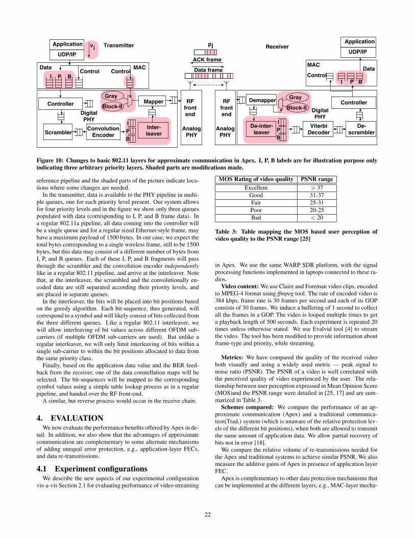
Modifications to the digital component of the PHY layer pipeline:We describe modifications needed to a standard 802.11 PHY layerpipeline to implement all features in Apex, and present it pictoriallyin Figure 10. All components in the picture are from the 802.11a
21
Application
ControlI P B
Data
Controller RFfrontend
AnalogPHY
DigitalPHY
UDP/IP
Mapper
Inter-leaver
IPB
ScramblerConvolution
Encoder
Gray
Block-II
ControlMAC
RFfrontend
AnalogPHY
Demapper Gray
Block-II
IPB
ViterbiDecoder
De-scrambler
Controller
Application
Data
UDP/IP
Control
MAC
I P B
vi
De-inter-leaver
Transmitter Receiver
DigitalPHY
Data frame
pj
ACK frame
Figure 10: Changes to basic 802.11 layers for approximate communication in Apex. I, P, B labels are for illustration purpose onlyindicating three arbitrary priority layers. Shaded parts are modifications made.
reference pipeline and the shaded parts of the picture indicate loca-tions where some changes are needed.
In the transmitter, data is available to the PHY pipeline in multi-ple queues, one for each priority level present. Our system allowsfor four priority levels and in the figure we show only three queuespopulated with data (corresponding to I, P, and B frame data). Ina regular 802.11a pipeline, all data coming into the controller willbe a single queue and for a regular sized Ethernet-style frame, mayhave a maximum payload of 1500 bytes. In our case, we expect thetotal bytes corresponding to a single wireless frame, still to be 1500bytes, but this data may consist of a different number of bytes fromI, P, and B queues. Each of these I, P, and B fragments will passthrough the scrambler and the convolution encoder independentlylike in a regular 802.11 pipeline, and arrive at the interleaver. Notethat, at the interleaver, the scrambled and the convolutionally en-coded data are still separated according their priority levels, andare placed in separate queues.
In the interleaver, the bits will be placed into bit positions basedon the greedy algorithm. Each bit-sequence, thus generated, willcorrespond to a symbol and will likely consist of bits collected fromthe three different queues. Like a regular 802.11 interleaver, wewill allow interleaving of bit values across different OFDM sub-carriers (if multiple OFDM sub-carriers are used). But unlike aregular interleaver, we will only limit interleaving of bits within asingle sub-carrier to within the bit positions allocated to data fromthe same priority class.
Finally, based on the application data value and the BER feed-back from the receiver, one of the data constellation maps will beselected. The bit-sequences will be mapped to the correspondingsymbol values using a simple table lookup process as in a regularpipeline, and handed over the RF front-end.
A similar, but reverse process would occur in the receive chain.
4. EVALUATIONWe now evaluate the performance benefits offered by Apex in de-
tail. In addition, we also show that the advantages of approximatecommunication are complementary to some alternate mechanismsof adding unequal error protection, e.g., application-layer FECs,and data re-transmissions.
4.1 Experiment configurationsWe describe the new aspects of our experimental configuration
vis-a-vis Section 2.1 for evaluating performance of video streaming
MOS Rating of video quality PSNR rangeExcellent > 37
Good 31-37Fair 25-31Poor 20-25Bad < 20
Table 3: Table mapping the MOS based user perception ofvideo quality to the PSNR range [25]
in Apex. We use the same WARP SDR platform, with the signalprocessing functions implemented in laptops connected to these ra-dios.
Video content: We use Claire and Foreman video clips, encodedto MPEG-4 format using ffmpeg tool. The rate of encoded video is384 kbps, frame rate is 30 frames per second and each of its GOPconsists of 30 frames. We induce a buffering of 1 second to collectall the frames in a GOP. The video is looped multiple times to geta playback length of 500 seconds. Each experiment is repeated 20times unless otherwise stated. We use Evalvid tool [4] to streamthe video. The tool has been modified to provide information aboutframe-type and priority, while streaming.
Metrics: We have compared the quality of the received videoboth visually and using a widely used metric — peak signal tonoise ratio (PSNR). The PSNR of a video is well correlated withthe perceived quality of video experienced by the user. The rela-tionship between user perception expressed in Mean Opinion Score(MOS)and the PSNR range were detailed in [25, 17] and are sum-marized in Table 3.
Schemes compared: We compare the performance of an ap-proximate communication (Apex) and a traditional communica-tion(Trad.) system (which is unaware of the relative protection lev-els of the different bit positions), when both are allowed to transmitthe same amount of application data. We allow partial recovery ofbits not in error [18].
We compare the relative volume of re-transmissions needed forthe Apex and traditional systems to achieve similar PSNR. We alsomeasure the additive gains of Apex in presence of application layerFEC.
Apex is complementary to other data protection mechanisms thatcan be implemented at the different layers, e.g., MAC-layer mecha-
22

0
10
20
30
40
50
0 5 10 15 20
PS
NR
(in d
B)
Experiment iteration
ApexTrad.
(a) PSNR of each iteration
0
10
20
30
40
50
ApexTrad.
PS
NR
(b) Average and Standard de-viation
Figure 12: PSNR differences between traditional and approx-imate communication with rate adaptation at a representativewireless environment (Claire video).
nisms (ZipTx and MRD), PHY-MAC mechanisms (PPR and SOFT).It was challenging for us to implement all of these schemes withinthe experimental WARP SDR platform. In Section 5 present an in-tuitive explanation of why other schemes, PPR, SOFT, MRD, andZipTx, are also expected to provide gains that are complementaryto Apex.
Trace-based evaluation for dynamic rate adaptation scenar-ios: In our SDR platform (WARP radios) a high latency is asso-ciated with processing RF samples from a received wireless frameand sending feedback to the transmitter for efficient rate adapta-tion. To avoid this latency related inaccuracy in evaluation, weadopt the practice of trace-driven analysis as is commonly appliedin evaluating rate adaptation algorithms with PHY layer processingneeds [34].
Symbols carrying application data are sent at different rates insuccession. We iteratively send small packets of 200 bytes at all thedifferent rates for building the trace. Also, we ensure that the BERis monotonically increasing with increasing data rate for a iteration(discarding samples for which this criteria does not hold) signifyinga coherent channel [34]. At the receiver we calculate the achievedthroughput by different data-rates and and only those symbols thatcorrespond to the rate selected by the rate adaptation algorithm areconsidered to be part of the media flow. As the selected rate variesover time, the symbols selected to be part of the flow at differenttime instants are picked accordingly. The actual performance ofthe media delivery process can then be evaluated by identifyingloss behaviors due to errors in an off-line manner.
4.2 Experimental resultsIn this section, we show how Apex helps improve the media
quality under different interference scenarios, how the gains of Apexare significant when compared to FEC-based or re-transmissionbased data recovery schemes, and describe some parameter selec-tions made in the system.
Apex vs traditional — a representative scenario: We presentthe relative performance for traditional media delivery and the Apexscheme with dynamic rate and constellation map adaptation en-abled for the same channel conditions as above in Figure 12. Theaverage uncoded BER for this scenario was 4.1 × 10⁻³ (corre-sponds to a coded BER of O(10−5), which is normal operatingcondition for 802.11 based radios). The average PSNR improve-ment due to Apex across a set of 20 runs was about 16 dB. The bet-ter performance of Apex stems from the fact that a throughput opti-mal data delivery can be further improved upon by the importance-aware mapping of data bits to bit positions within symbols.
We next illustrate how the dynamic adaptation of constellationmap is useful to improving the performance of Apex.
Impact of constellation map selection: The best choice of con-stellation map depends both on the channel conditions (pj values)
Video Trad. Apex (Gray) Apex (Block)Claire 21.8 29.5 37.8Foreman 21.0 34.5 31.0
Table 4: Table showing the PSNR for the two video clips in therepresentative wireless scenario with statically chosen constel-lation map.
0
10
20
30
40
50
60
0 2 4 6 8 10 12 14 16
PS
NR
Time(in seconds)
Switching points
Apex w/ switchingGray
BlockTrad.
Figure 13: Dynamic switching of data encoding scheme com-puted based on the utility of each encoding alternative (Blockand Gray).
and the differential value of application bit (vi values). channelconditions. We demonstrate this in turn.
- Dependence on application data: For the same representativescenario as in Figure 12, we show the relative performance of tradi-tional and Apex for two different video clips, Claire and Foreman,in Table 4, but with statically chosen constellation maps for the en-tire duration of the clip. Apex outperforms the traditional systemin all cases. But the relative amount of improvement depends onthe specific constellation map selection. Due to the distribution ofbytes between I-, P-, and B-frames in these clips, the relative valueof different data bits are different in these two schemes. As a conse-quence, Gray code leads to a better average PSNR performance forthe Foreman video than Block code, while the reverse is true for theClaire video. By dynamically selecting the most appropriate con-stellation map, Apex would be able to deliver the best performanceamong various alternatives.
- Dependence on channel conditions: We next illustrate how thedynamic adaptation of the constellation map occurs in practice, alsodue to changing channel conditions (Figure 13). The figure showshow the dynamic choice of the data encoding scheme ensures thatthe best encoding scheme is picked as the quality of the channelchanges. In particular, our algorithm decides to switch constella-tion maps around time 1.8, 3.3, and 10.9 seconds, soon after thePSNR quality using the constellation map falls below the other al-ternative. We also show the performance of traditional communica-tion system in the figure for the sake of completeness. We find thatApex performs better than traditional communication at all times.
Currently, our feedback latencies are significantly higher sincethe decoding operation with different encoding schemes are per-formed in the associated laptop, incurring high latencies, althoughthey are adequate to provide performance gains. A future version
23
0
10
20
30
40
50
5760 Kb/sO(10-2)
3450 Kb/sO(10-3)
500 Kb/s O(10-4)
PS
NR
Interfering traffic, BER observed
Trad.Apex
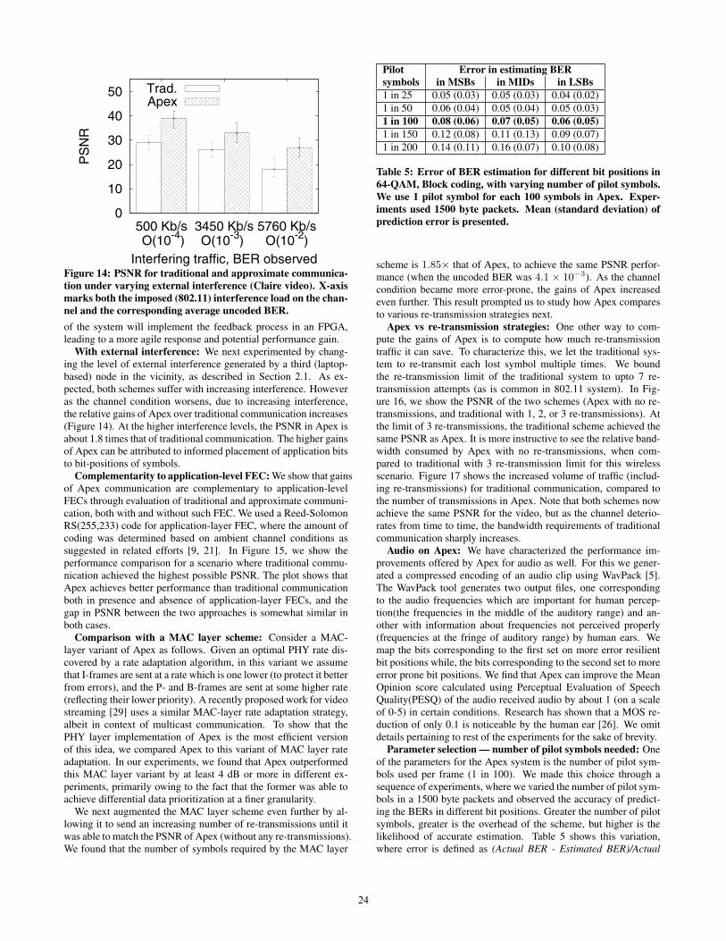
Figure 14: PSNR for traditional and approximate communica-tion under varying external interference (Claire video). X-axismarks both the imposed (802.11) interference load on the chan-nel and the corresponding average uncoded BER.
of the system will implement the feedback process in an FPGA,leading to a more agile response and potential performance gain.
With external interference: We next experimented by chang-ing the level of external interference generated by a third (laptop-based) node in the vicinity, as described in Section 2.1. As ex-pected, both schemes suffer with increasing interference. Howeveras the channel condition worsens, due to increasing interference,the relative gains of Apex over traditional communication increases(Figure 14). At the higher interference levels, the PSNR in Apex isabout 1.8 times that of traditional communication. The higher gainsof Apex can be attributed to informed placement of application bitsto bit-positions of symbols.
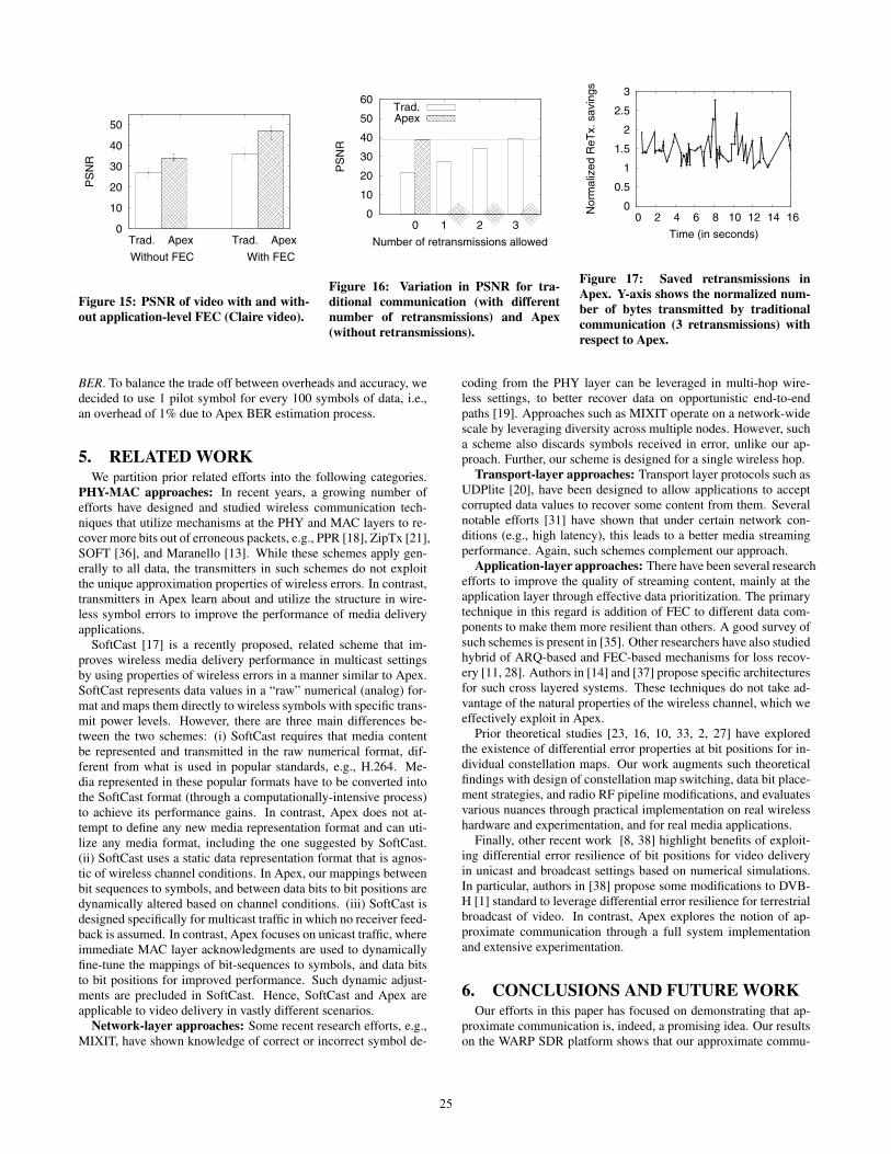
Complementarity to application-level FEC: We show that gainsof Apex communication are complementary to application-levelFECs through evaluation of traditional and approximate communi-cation, both with and without such FEC. We used a Reed-SolomonRS(255,233) code for application-layer FEC, where the amount ofcoding was determined based on ambient channel conditions assuggested in related efforts [9, 21]. In Figure 15, we show theperformance comparison for a scenario where traditional commu-nication achieved the highest possible PSNR. The plot shows thatApex achieves better performance than traditional communicationboth in presence and absence of application-layer FECs, and thegap in PSNR between the two approaches is somewhat similar inboth cases.
Comparison with a MAC layer scheme: Consider a MAC-layer variant of Apex as follows. Given an optimal PHY rate dis-covered by a rate adaptation algorithm, in this variant we assumethat I-frames are sent at a rate which is one lower (to protect it betterfrom errors), and the P- and B-frames are sent at some higher rate(reflecting their lower priority). A recently proposed work for videostreaming [29] uses a similar MAC-layer rate adaptation strategy,albeit in context of multicast communication. To show that thePHY layer implementation of Apex is the most efficient versionof this idea, we compared Apex to this variant of MAC layer rateadaptation. In our experiments, we found that Apex outperformedthis MAC layer variant by at least 4 dB or more in different ex-periments, primarily owing to the fact that the former was able toachieve differential data prioritization at a finer granularity.
We next augmented the MAC layer scheme even further by al-lowing it to send an increasing number of re-transmissions until itwas able to match the PSNR of Apex (without any re-transmissions).We found that the number of symbols required by the MAC layer
Pilot Error in estimating BERsymbols in MSBs in MIDs in LSBs1 in 25 0.05 (0.03) 0.05 (0.03) 0.04 (0.02)1 in 50 0.06 (0.04) 0.05 (0.04) 0.05 (0.03)1 in 100 0.08 (0.06) 0.07 (0.05) 0.06 (0.05)1 in 150 0.12 (0.08) 0.11 (0.13) 0.09 (0.07)1 in 200 0.14 (0.11) 0.16 (0.07) 0.10 (0.08)
Table 5: Error of BER estimation for different bit positions in64-QAM, Block coding, with varying number of pilot symbols.We use 1 pilot symbol for each 100 symbols in Apex. Exper-iments used 1500 byte packets. Mean (standard deviation) ofprediction error is presented.
scheme is 1.85× that of Apex, to achieve the same PSNR perfor-mance (when the uncoded BER was 4.1 × 10⁻³). As the channelcondition became more error-prone, the gains of Apex increasedeven further. This result prompted us to study how Apex comparesto various re-transmission strategies next.
Apex vs re-transmission strategies: One other way to com-pute the gains of Apex is to compute how much re-transmissiontraffic it can save. To characterize this, we let the traditional sys-tem to re-transmit each lost symbol multiple times. We boundthe re-transmission limit of the traditional system to upto 7 re-transmission attempts (as is common in 802.11 system). In Fig-ure 16, we show the PSNR of the two schemes (Apex with no re-transmissions, and traditional with 1, 2, or 3 re-transmissions). Atthe limit of 3 re-transmissions, the traditional scheme achieved thesame PSNR as Apex. It is more instructive to see the relative band-width consumed by Apex with no re-transmissions, when com-pared to traditional with 3 re-transmission limit for this wirelessscenario. Figure 17 shows the increased volume of traffic (includ-ing re-transmissions) for traditional communication, compared tothe number of transmissions in Apex. Note that both schemes nowachieve the same PSNR for the video, but as the channel deterio-rates from time to time, the bandwidth requirements of traditionalcommunication sharply increases.
Audio on Apex: We have characterized the performance im-provements offered by Apex for audio as well. For this we gener-ated a compressed encoding of an audio clip using WavPack [5].The WavPack tool generates two output files, one correspondingto the audio frequencies which are important for human percep-tion(the frequencies in the middle of the auditory range) and an-other with information about frequencies not perceived properly(frequencies at the fringe of auditory range) by human ears. Wemap the bits corresponding to the first set on more error resilientbit positions while, the bits corresponding to the second set to moreerror prone bit positions. We find that Apex can improve the MeanOpinion score calculated using Perceptual Evaluation of SpeechQuality(PESQ) of the audio received audio by about 1 (on a scaleof 0-5) in certain conditions. Research has shown that a MOS re-duction of only 0.1 is noticeable by the human ear [26]. We omitdetails pertaining to rest of the experiments for the sake of brevity.
Parameter selection — number of pilot symbols needed: Oneof the parameters for the Apex system is the number of pilot sym-bols used per frame (1 in 100). We made this choice through asequence of experiments, where we varied the number of pilot sym-bols in a 1500 byte packets and observed the accuracy of predict-ing the BERs in different bit positions. Greater the number of pilotsymbols, greater is the overhead of the scheme, but higher is thelikelihood of accurate estimation. Table 5 shows this variation,where error is defined as (Actual BER - Estimated BER)/Actual
24
0
10
20
30
40
50
ApexTrad.ApexTrad.
PS
NR
Without FEC With FEC
Figure 15: PSNR of video with and with-out application-level FEC (Claire video).
0
10
20
30
40
50
60
3210
PS
NR
Number of retransmissions allowed
Trad.Apex
Figure 16: Variation in PSNR for tra-ditional communication (with differentnumber of retransmissions) and Apex(without retransmissions).
0
0.5
1
1.5
2
2.5
3
0 2 4 6 8 10 12 14 16
Nor
mal
ized
ReT
x. s
avin
gs
Time (in seconds)
Figure 17: Saved retransmissions inApex. Y-axis shows the normalized num-ber of bytes transmitted by traditionalcommunication (3 retransmissions) withrespect to Apex.
BER. To balance the trade off between overheads and accuracy, wedecided to use 1 pilot symbol for every 100 symbols of data, i.e.,an overhead of 1% due to Apex BER estimation process.
5. RELATED WORKWe partition prior related efforts into the following categories.
PHY-MAC approaches: In recent years, a growing number ofefforts have designed and studied wireless communication tech-niques that utilize mechanisms at the PHY and MAC layers to re-cover more bits out of erroneous packets, e.g., PPR [18], ZipTx [21],SOFT [36], and Maranello [13]. While these schemes apply gen-erally to all data, the transmitters in such schemes do not exploitthe unique approximation properties of wireless errors. In contrast,transmitters in Apex learn about and utilize the structure in wire-less symbol errors to improve the performance of media deliveryapplications.
SoftCast [17] is a recently proposed, related scheme that im-proves wireless media delivery performance in multicast settingsby using properties of wireless errors in a manner similar to Apex.SoftCast represents data values in a “raw” numerical (analog) for-mat and maps them directly to wireless symbols with specific trans-mit power levels. However, there are three main differences be-tween the two schemes: (i) SoftCast requires that media contentbe represented and transmitted in the raw numerical format, dif-ferent from what is used in popular standards, e.g., H.264. Me-dia represented in these popular formats have to be converted intothe SoftCast format (through a computationally-intensive process)to achieve its performance gains. In contrast, Apex does not at-tempt to define any new media representation format and can uti-lize any media format, including the one suggested by SoftCast.(ii) SoftCast uses a static data representation format that is agnos-tic of wireless channel conditions. In Apex, our mappings betweenbit sequences to symbols, and between data bits to bit positions aredynamically altered based on channel conditions. (iii) SoftCast isdesigned specifically for multicast traffic in which no receiver feed-back is assumed. In contrast, Apex focuses on unicast traffic, whereimmediate MAC layer acknowledgments are used to dynamicallyfine-tune the mappings of bit-sequences to symbols, and data bitsto bit positions for improved performance. Such dynamic adjust-ments are precluded in SoftCast. Hence, SoftCast and Apex areapplicable to video delivery in vastly different scenarios.
Network-layer approaches: Some recent research efforts, e.g.,MIXIT, have shown knowledge of correct or incorrect symbol de-
coding from the PHY layer can be leveraged in multi-hop wire-less settings, to better recover data on opportunistic end-to-endpaths [19]. Approaches such as MIXIT operate on a network-widescale by leveraging diversity across multiple nodes. However, sucha scheme also discards symbols received in error, unlike our ap-proach. Further, our scheme is designed for a single wireless hop.
Transport-layer approaches: Transport layer protocols such asUDPlite [20], have been designed to allow applications to acceptcorrupted data values to recover some content from them. Severalnotable efforts [31] have shown that under certain network con-ditions (e.g., high latency), this leads to a better media streamingperformance. Again, such schemes complement our approach.
Application-layer approaches: There have been several researchefforts to improve the quality of streaming content, mainly at theapplication layer through effective data prioritization. The primarytechnique in this regard is addition of FEC to different data com-ponents to make them more resilient than others. A good survey ofsuch schemes is present in [35]. Other researchers have also studiedhybrid of ARQ-based and FEC-based mechanisms for loss recov-ery [11, 28]. Authors in [14] and [37] propose specific architecturesfor such cross layered systems. These techniques do not take ad-vantage of the natural properties of the wireless channel, which weeffectively exploit in Apex.
Prior theoretical studies [23, 16, 10, 33, 2, 27] have exploredthe existence of differential error properties at bit positions for in-dividual constellation maps. Our work augments such theoreticalfindings with design of constellation map switching, data bit place-ment strategies, and radio RF pipeline modifications, and evaluatesvarious nuances through practical implementation on real wirelesshardware and experimentation, and for real media applications.
Finally, other recent work [8, 38] highlight benefits of exploit-ing differential error resilience of bit positions for video deliveryin unicast and broadcast settings based on numerical simulations.In particular, authors in [38] propose some modifications to DVB-H [1] standard to leverage differential error resilience for terrestrialbroadcast of video. In contrast, Apex explores the notion of ap-proximate communication through a full system implementationand extensive experimentation.
6. CONCLUSIONS AND FUTURE WORKOur efforts in this paper has focused on demonstrating that ap-
proximate communication is, indeed, a promising idea. Our resultson the WARP SDR platform shows that our approximate commu-
25

nication system, provides significant improvement in video quality(ranging from a 5 dB to 20 dB in different scenarios). However, thisis a small first step in realizing the full capability of this system.
We believe this work leaves open a few optimization problemsthat should lead to further performance gains.
For example, a joint construction of data modulation schemesand constellation map selection might lead to further performancegains. In particular, since our goal is unequal protection of bit po-sitions, modulation schemes in which constellation points are un-equally spaced, might be useful to explore.
Similarly, the effect of the buffering induced by Apex, on theperformance needs to be better understood.
A FPGA based implementation of Apex scheme would be neces-sary for satisfactorily addressing the above. We are currently build-ing such a system, using which, in future we will explore these andmultiple other issues.
7. ACKNOWLEDGMENTSWe would like to thank Sateesh Addepalli for providing us with
various comments and opinions that helped us improve the qual-ity of the paper submitted to this conference. We are also gratefulto our shepherd Srikanth Krishnamurthy whose feedback helpedbring the paper to its final form. Sayandeep Sen and Suman Baner-jee were supported in part by a Cisco University Research Program(URP) award and through multiple awards from the US NationalScience Foundation including CNS-0916955, CNS-0855201, CNS-0751127, CNS-0627589, CNS-0627102, and CNS-0747177.
8. REFERENCES[1] Hierarchical modulation in DVB-T.
http://www.dvb.org/technology/fact_sheets/WP01_DVB-T%20Hierarchical.pdf.
[2] Hierarchical QAM modulation.http://en.wikipedia.org/wiki/Hierarchical_modulation.
[3] MPEG-4, Moving Picture Experts Group-4 Standard.http://www.chiariglione.org/mpeg/standards/mpeg-4/mpeg-4.htm.
[4] Video Quality Evaluation Tool-set.http://www.tkn.tu-berlin.de/research/evalvid/.
[5] WavPack Audio Compression. http://www.wavpack.com/.[6] Wireless Open-Access Research Platform (WARP).
http://warp.rice.edu/.[7] Wireless Open-Access Research Platform (WARP) Public
Forum. http://warp.rice.edu/forums.[8] A. Abdurrhman and M. Woodward. Unequal Error protection
of H.264/AVC video Using Hiererchical QAM. InTelekomunikacioni forum TELFOR, 2008.
[9] J. Byers, M. Luby, M. Mitzenmacher, and A. Rege. A digitalfountain approach to reliable distribution of bulk data. InSIGCOMM. ACM, 1998.
[10] A. R. Calderbank and N. Seshadri. Multilevel codes forunequal error protection. In IEEE Transactions onInformation Theory, volume 39, pages 1234–1248, 1993.
[11] N. Feamster and H. Balakrishnan. Packet Loss Recovery forStreaming Video. In Packet Video Workshop, 2002.
[12] F. Gray. Pulse code communication. U.S. Patent 2,632,058,1947.
[13] B. Han, A. Schulman, F. Gringoli, N. Spring,B. Bhattacharjee, L. Nava, L. Ji, S. Lee, and R. Miller.Maranello: Practical Partial Packet Recovery for 802.11. InNSDI, 2010.
[14] W. Heinzelman. Application Specific Protocol Architecturesfor Wireless Networks. Phd Thesis, 2000.
[15] U. Horn, K. Stuhmuller, M. Link, and B. Girod. RobustInternet video transmission based on scalable coding andunequal error protection. In Signal Processing: ImageCommunication, 1999.
[16] M. Isaka, M. P. C. Fossorier, R. H. Morelos-Zaragoza, S. Lin,and H. Imai. Multilevel Coded Modulation for Unequal ErrorProtection and Multistage Decoding - Part II: AsymmetricConstellations. IEEE Trans. Commun, 48:774–786, 1999.
[17] S. Jakubczak, H. Rabul, and D. Katabi. SoftCast: One Videoto Serve All Wireless Receivers. MIT-CSAIL-TR-2009-005.
[18] K. Jamieson and H. Balakrishnan. PPR: partial packetrecovery for wireless networks. In SIGCOMM, 2007.
[19] S. Katti, D. Katabi, H. Balakrishnan, and M. Medard.Symbol-level Network Coding for Wireless Mesh Networks.In ACM Sigcomm, 2008.
[20] L. Larzon and et. al. The udp-lite protocol.http://www.ietf.org/rfc/rfc3828.txt.
[21] K. C.-J. Lin, N. Kushman, and D. Katabi. ZipTx: exploitingthe gap between bit errors and packet loss. In ACM Mobicom,pages 351–362, New York, NY, USA, 2008. ACM.
[22] A. Majumdar, D. Sachs, I. Kozintsev, K. Ramchandran, andM. Yeung. Multicast and unicast real-time video streamingover wireless LANs. IEEE Transactions on Circuits andSystems for Video Technology, 2002.
[23] R. H. Morelos-Zaragoza, M. P. C. Fossorier, S. Lin, andH. Imai. Multilevel Coded Modulation for Unequal ErrorProtection and Multistage Decoding-Part I: SymmetricConstellations. In IEEE Transactions on Communications,1999.
[24] T. Nguyen and A. Zakhor. Distributed Video Streaming withForward Error Correction. In Proc. Packet Video Workshop,2002.
[25] Z. Orlov. Network-driven adaptive video streaming inwireless environments. PIMRC, 2008.
[26] A. Rix, J. Beerends, M. Hollier, and A. Hekstra. PerceptualEvaluation of Speech Quality (PESQ)-A New Method forSpeech Quality Assessment of Telephone Networks andCodecs. In IEEE International Conference on Acoustics,Speech, and Signal Processing, 2001.
[27] M. Sajadieh, F. Kschischang, and A. Leon-Garcia.Modulation-assisted unequal error protection over the fadingchannel. In IEEE Transactions on Vehicular Technology,1998.
[28] H. Seferoglu, Y. Altunbasak, O. Gurbuz, and O. Ercetin.Rate-Distortion Optimized Joint ARQ-FEC Scheme forReal-Time Wireless Multimedia. In ICC, 2005.
[29] S. Sen, N. K. Madabushi, and S. Banerjee. Scalable WiFiMedia Delivery through Adaptive Broadcasts. In NSDI,2010.
[30] S. Sen, S. Schmitt, M. Donahue, and S. Banerjee. Exploiting"Approximate Communication" for Mobile MediaApplications. In HotMobile, 2009.
[31] A. Singh, A. Konrad, and A. D. Joseph. Performanceevaluation of UDPlite for cellular video. In NOSSDAV.ACM, 2001.
[32] D. Tian, X. Li, G. Al-regib, Y. Altunbasak, and J. R. Jackson.Optimal packet scheduling for wireless video streaming witherror-prone feedback. In IEEE WCNC, 2004.
[33] G. Ungerboeck. Channel Coding with Multilevel/PhaseSignals. In IEEE Trans. on Information Theory, 2006.
[34] M. Vutukuru, H. Balakrishnan, and K. Jamieson.Cross-Layer Wireless Bit Rate Adaptation. In ACMSIGCOMM, Barcelona, Spain, August 2009.
[35] Y. Wang and Q.-F. Zhu. Error control and concealment forvideo communication: a review. Proceedings of the IEEE,86(5):974–997, May 1998.
[36] G. R. Woo, P. Kheradpour, D. Shen, and D. Katabi. Beyondthe bits: cooperative packet recovery using physical layerinformation. In MOBICOM, 2007.
[37] S. Worrall, S. Fabri, A. Sadka, and A. Kondoz. Prioritisationof Data Partitioned MPEG-4 Video over Mobile Networks.In European Transactions on Telecommunications, 2001.
[38] Z. Wu, J. Boyce, and A. Stein. An Unequal Error ProtectionFramework for DVB-H and Its Application to VideoStreaming. In IEEE Globecom, 2008.
26