design and implementation of a three-wheel multi-purpose
TRANSCRIPT

2021, VOL. 5, NO: 2, 116-125
116
www.ijastech.org e-ISSN: 2587-0963
Design and Implementation of A Three-Wheel Multi-Purpose Electric Vehicle with
Finite Elements Analysis
Gülüstan Tuğçe Alvalı1, Ali Balbay2, Serkan Güneş3, Burak Yenipınar4, M. Cem Çatalbaş5, Turan Şişman2
0000-0003-0315-506X, 0000-0002-6517-1201,0000-0003-3976-0771, 0000-0002-5997-944X, 0000-0002-9291-1180, 0000-0002-1923-8217
1OSTIM Technical University, Hybrid and Electric Vehicle Technology Program, MYO, Ankara, Turkey 2OSTIM Technical University, Machine Program, MYO, Ankara, Turkey 3OSTIM Technical University, Mechatronics Program, MYO, Ankara, Turkey 4OSTIM Technical University, Electronic Program, MYO, Ankara, Turkey 51st Organized Industrial Zone Vocational School, Department of Electronics and Automation, Ankara University, Ankara/Turkey
1. Introduction
Today, a significant part of the world's energy needs is met by
fossil energy sources such as coal, natural gas and oil. The more
population of countries rises, the more passenger vehicles are used.
Due to the rising number of vehicles, the need for fuel increases as
well. The need for alternative and renewable energy sources is an
inevitable fact both in order to balance the fossil fuel produc-
tion/consumption rate and to take measures in situations that may
cause significant long-term environmental downsides such as
global warming [1]. 20% of the carbon dioxide (CO2) gas emis-
sions of European Union countries are caused by road transport [2].
The polluting effect of the fossil fuels on the atmosphere and the
rapid rise on the amount of CO2 gas has resulted in the need to
develop alternative fuels for road vehicles and accelerated the tran-
sition to electric vehicle technology. Studies for this purpose not
only present predictions on the environmental damages of fossil
fuels but also reveal the necessity to take measures in the light of
these predictions.
The number of electric vehicles in Turkey is approximately
1,150 units and the number of hybrid vehicles is around 15,000.
According to TURKSTAT data, the number of electric and hybrid
cars was 1,685 in 2017 and 5,367 in 2018. The number of electric
and hybrid vehicles used in 2019 was 14,115 units, tripling that
of2018. Considering this data, the number of electric cars is ex-
pected to increase significantly in the coming years (Figure 1) [3].
In parallel with the spread of electric vehicles, new production
technologies have been developed as well. The design and produc-
tion processes of chassis for electric vehicles are one of them. The
main structural element of the vehicles is the chassis. Thus, the de-
sign procedure of the chassis is vital for vehicles. The chassis is a
structure that carries both the load applied in the vehicle and the
weights of the vehicle. The chassis is expected to be light, environ-
ment friendly, and should safely carry the loads it is exposed to
with longevity. The research indicates that electric vehicle chassis
Abstract With technological developments and carbon emission reaching dangerous levels in the
world, it is inevitable that electric vehicles will become the dominant transportation tech-nology of the future. Studies on electric vehicles have become very popular today. In the automotive sector, sectoral dynamics and needs are rapidly changing; restrictions and de-mands are bound by strict rules and high value-added innovative studies are applied inten-sively. Supporting this area with academic data will contribute to research and develop-ment activities in this field. In this study, analysis and production studies were performed on a 3-wheeled vehicle chassis driven by electric energy. The chassis structure was de-signed and analyzed with details. The chassis aimed to be produced as a result of the study was analyzed in detail according to brake, modal and cornering analysis. As a result of these analyses, it was found that this chassis has a reliable structure according to the spec-ified driving dynamics parameters. By adopting new requirements, technologies and anal-ysis outputs for the system, a modular platform structure that can be used for various ap-plications were created. The design and production processes of an innovative and appli-cable chassis structure for the electric vehicle ecosystem are given in detail. Keywords: Electric vehicle, ANSYS, Finite elements method, Chassis design, Stress analysis, Nat-ural frequency.
Keywords: At least 4 keywords; In alphabetical order; Separated by semicolon; Design of experi-ments (Times New Roman, font 9, upper case at the beginning of each keyword)
Research Article
https://doi.org/10.30939/ijastech..871684
Received 02.02.2021 Revised 04.04.2021
Accepted 05.04.2021
* Corresponding author
Gülüstan Tuğçe Alvalı
Address:OSTIM Technical University
Hybrid and Electric Vehicle Technology
Program, MYO, Ankara, Turkey

Alvalı et al./ International Journal of Automotive Science and Technology 5 (2): 116-125, 2021
117
is the most important feature worked on for being light and durable.
In this study, producing a low cost and compact three-wheel multi-
purpose electric vehicle is aimed in order to comply with the micro
mobility, which is becoming more popular in the field of transpor-
tation due to its efficiency, low production and fuel cost.
Fig. 1. Number of hybrid-electric vehicles used in Turkey [3]
Use of electric vehicles has been common the most in European
countries. Only electric vehicles were used more widely in Euro-
pean countries until 2012, but interest in hybrid-electric vehicles
also increased due to the limited number of electric vehicle models.
The number of electric and hybrid vehicles in European countries
is given in Figure 2 [1, 3].
Fig. 2. Number of hybrid and electric vehicles used in Europe[1]
As shown in Figure 2, electric vehicles and related theoretical
and practical applications together with development studies will
be of increasing importance in the upcoming years. In this study, a
chassis design was studied for use in the 3-wheel, electrically
driven, freight and passenger transportation. The design bounda-
ries of the chassis were determined and safety analyses were car-
ried out to identify the safety coefficient of the chassis by selecting
materials and batteries taking into account the weight of the vehicle.
Chassis analysis; structural analysis, corner analysis and brake
analysis were carried out and then prototype production of the
chassis, which was proven to be reliable with detailed analyses,
was performed.
In this study, some general designs based on different road loads
and deformation modes as well as reseal-measured suspension
connections were studied. In the study, which developed a simple
mathematical model to get an idea of the design objectives suitable
for the vehicle structure and compare structural hardness with sus-
pension hardness, a finite element model was created for both the
stand-alone frame and the entire chassis/suspension, taking into ac-
count these hardness targets, and this model was analyzed with
ANSYS software [4].
In Cinali's 2012 study, an analysis of the vehicle produced by
the university was carried out. First of all, the vehicle was modeled
in 3D in CAD and the chassis, which was designed in 3D, was
analyzed with the finite element method. As a result of the analysis,
critical areas of the chassis were determined according to stress and
deformation values, the safety coefficient and natural frequency
value of the chassis were calculated [5]. Mat and Ghani's research
conducted in 2012 carried out a light chassis development for
"Eco-Challenge" race cars that could safely withstand loads and
compulsions. Chassis analysis was carried out by addressing nor-
mal car loads such as engine and driver weight, acceleration, brak-
ing and cornering forces. When the results of the analysis were ex-
amined, it was seen that the chassis supported most loading condi-
tions [6].
In the study conducted by Agrawal and Razik (2013), studies
examining car chassis with different analysis techniques were re-
viewed. It was observed that there are many analytical and experi-
mental techniques for the analysis of automobile chassis, studies
such as fatigue analysis, static analysis and dynamic analysis were
carried out [7]. In the 2013 study of Patil and his friends, stretching
analysis was performed with the finite element method of the stair
type low loader truck chassis consisting of C-beam design for 7.5-
ton application. The thickness of the side element, the thickness of
the intermediate element and the position of the inter-mediate ele-
ment from the rear end were changed to achieve a reduction in
stress size at the critical point of the chassis frame. Numerical re-
sults showed that changing the position of the inter-mediate ele-
ment could be a good alternative if a change in thick-ness was not
possible [8].
In 2014, Zeina Bitar and Samih Al Jabistudied the suitability of
the use of an IM and a Field Oriented Control (FOC)-based in-
verter in electric vehicles. As a result of their work, they proved
that the use of asynchronous motors in electric vehicles is appro-
priate [9].
Babaarslan's 2014 study investigated the design and production
of an optimal vehicle for an M1-class electric sports vehicle with
the help of analyses and tests. This vehicle design is planned to be
a faultless, world-class vehicle by carrying out production controls
[10]. In the 2015 study conducted by Contractor and his friends,
the Eicher 11.10 model car chassis design and the finite element
analysis of the chassis were performed. The results of the analysis
were observed to be well below the allowed values and it was de-
cided that the chassis had safety [11].

Alvalı et al./ International Journal of Automotive Science and Technology 5 (2): 116-125, 2021
118
In 2015, Yılmaz examined DC motor, induction motor, perma-
nent magnet synchronous motor (PMSM) and reluctance motors
used in plug-in electric vehicles (PEVs). As a result of its review,
PEVs stated that the perfect solution for vehicles is PMSM due to
its advantages such as high efficiency, low volume and weight,
good field-weakening capability, torque contribution of reluctance.
However, the high cost of PMSMs and continuing developments
in magnet technology were found to be the disadvantages of this
topology. For this reason, the author stated that IMs and PMSMs
are commonly preferred as driving power in PEVs today [12].
In the 2015 study conducted by Makhrojan and his friends, chas-
sis was redesigned and analyzed to restore strength to an electric
city car chassis. The chassis design was carried out with the Solid-
works program, and the analysis was performed using the final el-
ement simulation software. As a result of the analysis, it was de-
termined that the frame was still under the elastic zone until the
monocoque frame design was safe to use [13]. The 2015 study by
Ekapun and his friends designed a new body of the modern elec-
tromagnetic tricycle to travel at a zero-emission airport. Automo-
tive dynamics theory and a brushless DC motor were used in the
design of the electromagnetic wheels of the tricycle. Additionally,
a design chassis was developed using ABAQUS with dynamic
analysis based on the chassis of an existing golf cart model. Finally,
a 3D printing prototype was produced to realistically represent
conceptual design and verify the functionality of the final design
on a small scale [14].
In a 2016 study by Yang and his friends, testing and analysis
were conducted for a Honda Accor PHEV, which have a serial-
parallel powertrain. NEDC cycle test, dynamic acceleration test
and static navigation test completed in a four-wheel-drive chassis
dynamometer at the China Automotive Engineering Research In-
stitute Power transmission system configuration design, control
strategy and fuel economy of the vehicle were analyzed and the
results showed that the serial-parallel configuration had the poten-
tial to reduce transmission mechanical losses and that serial oper-
ating mode tended to be more efficient in most operating condi-
tions [15].
The 2017 study by Trovão and his friends studied the integration
of a Super Capacitor (SC) package in a three-wheeled electric ve-
hicle, taking into account the energy and power division manage-
ment strategy. An energy management strategy based on a com-
prehensive fuzzy logic checker approach was implemented to im-
prove the global efficiency and performance of the vehicle under
review. The proposed control and management strategy made it
possible for the battery to meet an average portion of power de-
mand, while the energy level of SC’s can be intelligently con-
trolled. The proposed strategy was presented as an easily integrated
strategy to other vehicles or different driving modes. The approach
was implemented with power-level in-cycle hardware (HIL) plat-
form for a reduced scale hybrid dual energy storage system [16].
In 2018, in the study of Savkin and his friends, structural anal-
yses of car suspensions were carried out taking into account the
different nature of the road surface. Loading spectrums on this con-
struction were obtained according to the dynamic model made in
the FRUND program. The possibility of replacing the material of
this structure, which provides the necessary strength and fatigue
properties of the structure, with the cheaper one [17].
In the 2018 study of Kurdi and his friends, vibration character-
istics of the electric bus chassis and natural frequency and mode
were determined. Three materials in various thickness measure-
ments were used for the design and they were simulated with the
help of the Abaqus program. As a result of the analysis, 6-mm-
thick AISI 4130 Alloy steel was selected as the best model with
less resonance probability [18]. In the 2018 study conducted by
Sutisna and Akbar, an electric vehicle chassis design was made. A
FEM simulation was used to simulate the different load and reac-
tion on the designed chassis. Von-Misses Stress, safety factor,
bending, torsional slip voltage and vibration analysis were per-
formed with the help of ANSYS program. As a result of the anal-
ysis, it was found that the designed chassis worked well and was
within safe zones [19]. A 2018 study by Ding and his friends de-
scribed a common chassis control system for electric vehicles that
controls longitudinal motion based on deviation movement. This
system can be used to improve the agility and stability of the vehi-
cle using the integration of the torque distribution unit and elec-
tronic stability control (ESC). In addition, this system can help
drivers navigate a bend smoothly prior to ESC intervention [20].
In 2018, another study conducted by Arifurrahman and his
friends modelled and analyzed the developing three-wheeled elec-
tric vehicle chassis for the delivery of goods. Three different types
of Alpha chassis were examined, and their amplitudes and natural
frequencies were determined thanks to their dynamic analysis. As
a result of the study, the Alpha 2 framework did best [21]. In 2019,
Gürel and his friends conducted a study of the parameters neces-
sary to optimize electric vehicles; engine selection, design criteria,
battery sizing and energy management. In the study, especially the
battery problem of electric vehicles was emphasized. Basic prob-
lems with the battery; high cost, weight problem and long charging
problem were handled in three main sections[22].
In the 2019 study conducted by Tsirogiannis and his friends, an
integrated methodology of developing an electric car chassis was
demonstrated. The main criteria for the development of the electric
car chassis are the elimination of cost and time, as well as an in-
crease in hardness and strength, which is subject to mass reducing.
They designed a chassis in accordance with the regulations of the
Shell Eco Marathon competition. With the designed chassis FEA
method, the condition of the chassis under stress was examined
with ANSYS program. Thus, the chassis design was realized with
an accurate ultra-fast and cost-effective method [23]. A structur-
ally balanced chassis was designed for an electric motorcycle in a
2018 study by Joel et al. simulated the real-time forces on the chas-
sis and suspension geometries. In the simulation, the voltage,
safety factor and deformation of the same structure were compared
with different materials in accordance with the strength, cost and
weight of the chassis to determine the material most suitable for
the chassis [24]. In 2019, Harušinec and his friends emphasized the
importance of the material in the three-wheeled vehicle chassis de-
sign study and aluminum material was selected to make the vehicle
light. Safety criteria were determined by analyzing the designed
chassis [25].

Alvalı et al./ International Journal of Automotive Science and Technology 5 (2): 116-125, 2021
119
27 works in 2019 featured a lightweight chassis design. A com-
bination chassis consisting of both steel and carbon-carbon com-
posite components (CFRP) was created by replacing heavy steel
cross elements with CFRP cross-elements, resulting in a 14.6% re-
duction in weight. Collision analysis was performed on all cases
using Radioss and the most suitable chassis combination was se-
lected depending on the result obtained from the collision analysis
and the torsion, cornering hardness values. In combination chassis,
weight was further reduced by 7.91% [26]. In the 2020 study of
Sánchez and his colleagues, an iteration algorithm was proposed,
during which a path and reference period were given to determine
the chassis that best suited to electric vehicles. Thanks to the pro-
posed methodology, battery weight was reduced by about 20%
compared to normal designs [27]. In the 2020 study conducted by
Nandhakumar and his friends, an electric motor-powered bus chas-
sis design was made. Aluminum alloys were used for the design of
the chassis, reducing chassis weight but not compromising safety.
Structural analyses of the designed chassis were carried out with
the help of an ANSYS program [28].
In the 2020 study of Chandramohan et al., they aimed to trans-
form the internal combustion Go-Kart engine into an electric-pow-
ered engine. They indicated that the Go-kart chassis, powered by
an electric motor, has a more complex structure than the chassis
used in the internal combustion engine and that some changes are
required for the conversion. Both chassis were designed by Solid-
works program, and analyzed for different types of impacts with
the help of ANSYS program. As a result of the analysis, load dis-
tributions and deformation results were compared [29]. In the 2020
study of Krishnamoorthi and his friends, electric Go-Kart design
and analysis calculations were made. The main purpose of the
study is to obtain a light and high-performance electric vehicle.
AISI 1018 was found to be suitable for the vehicle material. The
SolidWorks program was used to design the chassis. With the
ANSYS program, deformation and equivalent stress were found
by analyzing the front, rear and side impacts of the chassis [30].
In the 2020 study conducted by Saplinova et al., the design and
test results for the main passive safety feature of Formula type
open-wheel racing cars and tubular space frame chassis were ex-
amined. A chassis strength analysis, results of front and side im-
pact tests and torsional stiffness calculations were performed for
the chassis of a racecar used by the team representing Shukhov
Belgorod State University of Technology [31]. Mohammed empir-
ically addressed this interim connection by analyzing the applica-
tion of an electric vehicle designed and built by automotive engi-
neering students at the Technical University of Munich (TUM) in
Germany. The students designed the tool to address mobility issues
for rural populations in Africa and aimed to provide better access
to local people's living needs such as health, education and
transport [32].
In the 2020 study of Shantika et al., the chassis design of a cross-
over vehicle was made. In the chassis design process, stress anal-
yses were carried out to determine the stresses formed on the chas-
sis. The design was done in CAD program and the analysis was
performed using FEA SolidWorks analysis. As a result of the anal-
ysis, the safety factor of the vehicle chassis was found to be 1.69
[33].
In this article, the first chapter discusses the studies about the use
of electric and hybrid electric vehicles usage both in Turkey and
worldwide. In the second part, material selection and necessary
equipment for the chassis design of the electric vehicle was deter-
mined. The reliability of the chassis is explained in the third section,
was determined by making modal, brake and cornering analyzes.
Electric vehicle chassis production presented as a result of the anal-
ysis was given in the fourth chapter. Finally, the result was dis-
cussed in the fifth chapter.
2. The Design of Multi-Purpose Electric Vehicle Chassis
Engineering design is an approach in which basic concepts such
as functionality, reliability, manufacturability, usability, and cost
of the resulting product are dealt with [34]. In this study, a design
with minimum cost and maximum safety has been introduced by
using an engineering approach. Factors affecting the chassis design
are shown in Table 1.
Table 1. Factors affecting chassis design
Passengers and load safety
Chassis Manufacturing
Easy removal and installation of parts during assembly process
Ease of manufacture (Technology compatibility)
While designing the chassis, criteria such as passenger safety, ease of manufacture and technology compatibility were taken into ac-count. The ladder type chassis was chosen as the chassis type to be designed. Figure 3 shows the ladder type chassis visually. This type of chassis is a frequently used in production and used mainly as automobile and truck chassis today [35].
Fig. 3. Ladder type chassis [35]
In cases where the chassis is desired to be light, aluminum is
used as the frame material [26]. However, being an unsafe frame
structure, it is risky for load, passenger and navigation safety. In
this study, steel (St 37) with higher strength values than aluminum
was preferred because safety was at the forefront as chassis mate-
rial, see Table 2.
Table 2. Mechanical properties of the material (St 37) to be used
Material Density (kg/m3)
Yield Strength (MPa)
Tensile Strength (MPa)
St-37 Steel
7850 235 360
Alvalı et al./ International Journal of Automotive Science and Technology 5 (2): 116-125, 2021
120
The three-wheeled chassis is a new intelligent transport system
that is a more convenient alternative to the mobility of the vehicle
than other four- and two-wheeled vehicles [36]. The vehicle is de-
signed to carry two passengers in the rear seat and one driver in the
front seat, single and three-wheeled. The driver will be carried at
the front and the load will be carried in the rear cab. Because the
designed vehicle is three-wheeled, driven by an electric motor, and
its design speed is lower than 45 km / h, it is classified as a three-
wheeled moped, namely L2e, according to the vehicle classifica-
tion criteria. General features of the L2e class vehicle are given in
Table 3.
Table 3. L2e class vehicle features
Driven by three wheels and electric motor
The maximum design speed of the vehicle ≤ 45km / h
Maximum drift rated power or net power ≤ 4000W
Mass in walking position ≤ 270 kg
A maximum of two seats, including the driver's seat
High torsional rigidity chassis are obtained when empty sections
are used in longitudinal and transverse carriers. Closed empty sec-
tions are used in longitudinal and transverse carriers and they have
a high mass, high cornering, and torsional strength moments. The
profile to be used in the chassis was selected as a 40x40 closed
empty section, see Figure 4. The chassis design performed using
the 40x40 empty sections is shown in Figure 4. Welded condition
is showed in Figure 5.
Fig. 4. Profile used in chassis design
Fig. 5. 3D Model of designed chassis.
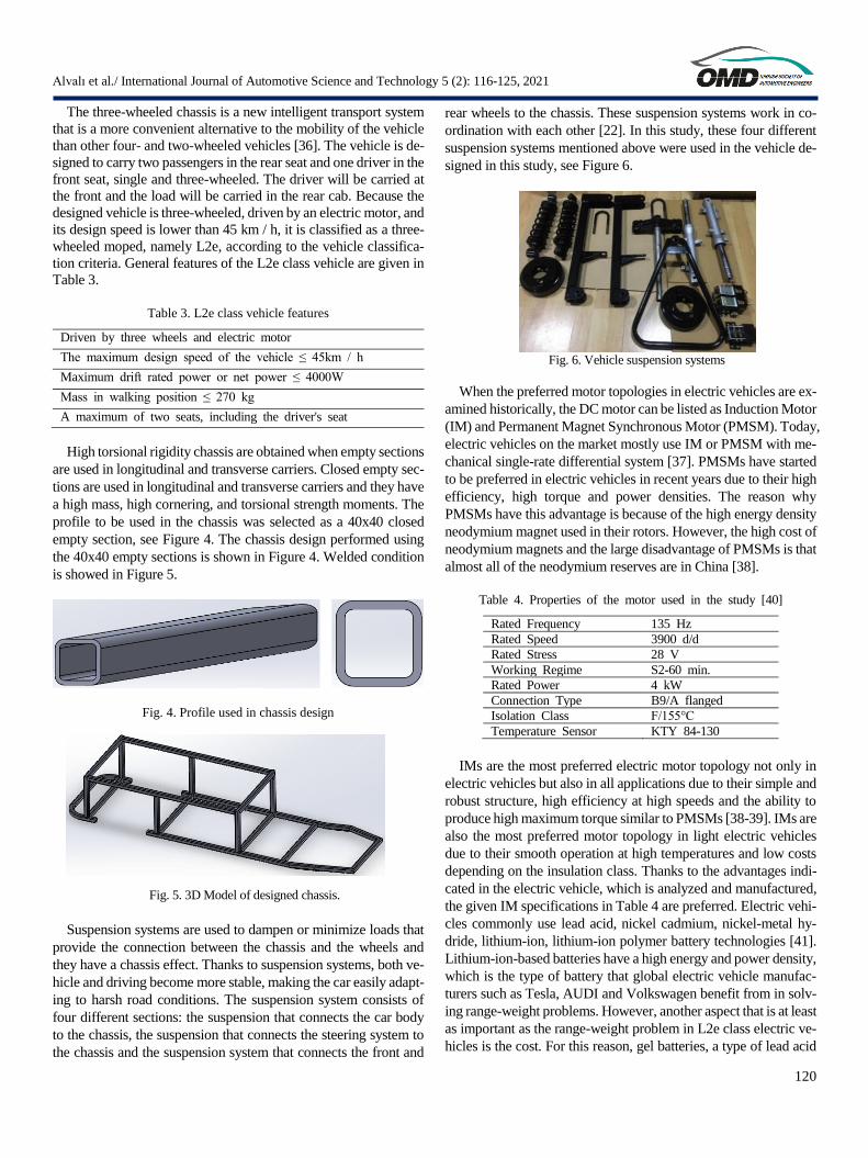
Suspension systems are used to dampen or minimize loads that
provide the connection between the chassis and the wheels and
they have a chassis effect. Thanks to suspension systems, both ve-
hicle and driving become more stable, making the car easily adapt-
ing to harsh road conditions. The suspension system consists of
four different sections: the suspension that connects the car body
to the chassis, the suspension that connects the steering system to
the chassis and the suspension system that connects the front and
rear wheels to the chassis. These suspension systems work in co-
ordination with each other [22]. In this study, these four different
suspension systems mentioned above were used in the vehicle de-
signed in this study, see Figure 6.
Fig. 6. Vehicle suspension systems
When the preferred motor topologies in electric vehicles are ex-
amined historically, the DC motor can be listed as Induction Motor
(IM) and Permanent Magnet Synchronous Motor (PMSM). Today,
electric vehicles on the market mostly use IM or PMSM with me-
chanical single-rate differential system [37]. PMSMs have started
to be preferred in electric vehicles in recent years due to their high
efficiency, high torque and power densities. The reason why
PMSMs have this advantage is because of the high energy density
neodymium magnet used in their rotors. However, the high cost of
neodymium magnets and the large disadvantage of PMSMs is that
almost all of the neodymium reserves are in China [38].
Table 4. Properties of the motor used in the study [40]
Rated Frequency 135 Hz
Rated Speed 3900 d/d
Rated Stress 28 V
Working Regime S2-60 min.
Rated Power 4 kW
Connection Type B9/A flanged
Isolation Class F/155°C
Temperature Sensor KTY 84-130
IMs are the most preferred electric motor topology not only in
electric vehicles but also in all applications due to their simple and
robust structure, high efficiency at high speeds and the ability to
produce high maximum torque similar to PMSMs [38-39]. IMs are
also the most preferred motor topology in light electric vehicles
due to their smooth operation at high temperatures and low costs
depending on the insulation class. Thanks to the advantages indi-
cated in the electric vehicle, which is analyzed and manufactured,
the given IM specifications in Table 4 are preferred. Electric vehi-
cles commonly use lead acid, nickel cadmium, nickel-metal hy-
dride, lithium-ion, lithium-ion polymer battery technologies [41].
Lithium-ion-based batteries have a high energy and power density,
which is the type of battery that global electric vehicle manufac-
turers such as Tesla, AUDI and Volkswagen benefit from in solv-
ing range-weight problems. However, another aspect that is at least
as important as the range-weight problem in L2e class electric ve-
hicles is the cost. For this reason, gel batteries, a type of lead acid

Alvalı et al./ International Journal of Automotive Science and Technology 5 (2): 116-125, 2021
121
battery, are used in light electric vehicles because they are durable
and cost-effective with a maintenance-free and deep discharge cy-
cle. The path taken by an electric vehicle depends on the type of
battery used and the number of batteries used [18].
3. The Finite Element Analysis of Vehicle Chassis Design
Stress distribution in chassis design is one of the most important
factors in determining the safety coefficient of the chassis. In order
to determine the safety coefficient, it is required to have stress dis-
tributions that will occur as a result of the forces affecting the de-
signed chassis. The 3D chassis model designed for chassis analysis
was transferred to the ANSYS finite elements package program.
Material mechanical properties were defined to the program from
ANSYS Engineering Data, see Figure 7.
Fig. 7. ANSYS engineering data.
Finite element analyzes were modelled in 3D using the "Static
Structural" module of ANSYS Workbench software. The chassis
designed in the SolidWorks program was saved in the "Parasolid"
format. Then it was transferred to the ANSYS Workbench pro-
gram and the finite element model was created by mesh. As a finite
element type, a 3-dimensional 10-node structural solid type tetra-
hedral element wasused. The mesh consists of 51,872 element and
118,245 points. The net mesh on the chassis is shown in Figure 8.
Fig. 8. Chassis mesh image. a) General view, b) Close view.
3.1 Modal Analysis of Chassis Design
Modal analysis was made to determine the natural frequency of
the chassis. The main purpose of doing this analysis was to see the
dynamic response to reach a vibrational result and to express this
answer in a mathematical model. Modal analysis was done for the
first 10 modes of vibration. The deformation and natural frequency
obtained for 10 modes are given in the tables.
Table 5. Chassis natural frequency and deformation values
Mode Natural Frequency(Hz)
Deformation (mm)
1 20,226 7,709
2 23,401 9,164
3 37,955 6,061
4 50,252 7,303
5 58,248 7,853
6 59,664 7,332
7 68,006 6,387
8 86,796 8,821
9 101,23 8,626
10 103,99 10,65
Fig. 9. a) Mode 1, b) Mode 2
Fig. 10. a) Mode 3, b) Mode 4
Fig. 11. a) Mode 5, b) Mode 6
Fig. 12. a) Mode 7, b) Mode 8
Fig. 13. a) Mode 9, b) Mode 10
As shown in Table 5. and Figure 9-13, the resulting stress and
deformation values were significantly small and did not cause plas-
tic deformation on the chassis.
3.2. Brake Analysis and Chassis Design Braking analysis was carried out in order to examine what
changes would occur on the vehicle chassis when a sudden brake
occurred with the vehicle. While calculating the brake acceleration,
the stop time and the maximum speed of the vehicle were taken

Alvalı et al./ International Journal of Automotive Science and Technology 5 (2): 116-125, 2021
122
into account. The stop time of the vehicle varies depending on per-
sonal and environmental conditions and it is between 0.3-0.7 sec-
onds on average [42]. When the maximum speed of the designed
vehicle was 45 km / h and the vehicle stop time was 5 seconds, the
braking acceleration was calculated as 2.5 m / s2.
The forces acting on the chassis; The effects of the driver, pas-
sengers and / or load, battery, engine weights and braking acceler-
ation planned to be transported in the trailer part were considered
in the chassis analysis. The forces acting on the chassis are given
in Table 6. The chassis was fixed from the wheel parts and the
forces and braking acceleration acting on it are shown in Figure 14.
Table 6. Forces acting on the chassis
Loads to be Applied on the Chassis Mass(kg)
Load 250
Driver 80
DC Motor 20
Gel Battery 160
Fig. 14. Forces affecting the chassis in braking analysis.
As a result of the braking analysis, a yield value of 274.49 MPa
was found on the chassis. Equivalent stress and total deformation
values showed that permanent deformations will not occur on the
vehicle chassis during sudden brakes and the vehicle will continue
on its way. The yield value and safety coefficient values formed on
the chassis are shown in Figure 15. and Figure 16.
Fig. 15. Yield value in the chassis
Fig. 16. Safety coefficient at braking
3.3. Cornering Analysis and Chassis Design
The cornering analysis was carried out to examine the reaction
of the vehicle chassis when it enters a sharp corner that it may be
encountered in today's conditions. In the vehicle corner analysis,
the corner with a sharp corner size of 50 m and the maximum speed
of the vehicle were considered as 45km / h, and the cornering ac-
celeration was calculated as 3,125 m / s2. The forces acting on the
chassis are given in Table 6 and fixed from the wheel parts. The
forces acting on the chassis and the cornering acceleration are
shown in Figure 17.
Fig. 17. Forces affecting the chassis in corner analysis.
As a result of the corner analysis, a yield value of 274.44 MPa
was found on the chassis. As a result of this analysis, it was ob-
served that the value stress and total deformation values examined
were low. This showed that the vehicle will remain intact when it
enters a sharp corner, and permanent deformations will not occur
on the car chassis. The yield value and safety coefficient values
formed in the chassis are shown in Figure 18.-19.
Fig. 18. Chassis yield value

Alvalı et al./ International Journal of Automotive Science and Technology 5 (2): 116-125, 2021
123
Fig.19. Cornering instant safety coefficient
4. Electric Vehicle Chassis Manufacturing
As a result of the analysis, it was seen that the designed chassis
was a safe chassis in all cases. In line with this result, prototype
production of the chassis was carried out taking into account the
design criteria, dimensional characteristics and analysis values of
the vehicle.
Welding operation was performed in combining profiles in the
chassis production. The most preferred welding types in the auto-
mobile sector are friction source, Oxy-Acetylene welding, sub-gas
(MIG and MAG) welded with melting electrode and resistance
point source [43]. In chassis production, MIG-MAG welding type
was preferred because it was fast and its cost was lower than the
other methods, see Figure 20.
Fig. 20. a) Chassis manufacturing b) Welded chassis
Suspension systems have the task of connecting the wheel to the
chassis, as well as dampening the chassis loads in certain propor-
tions, allowing the vehicle to move safely. After the completion of
welding operations and assembly of all profiles, the steering, sus-
pension and wheel systems were assembled, see Figure 21.
Fig. 21. Suspension and wheel system installation
After the production and supply processes of the chassis and all
the subsystems connected to the chassis were completed, the basic
structure of the vehicle was formed by going to the final assembly
and the integration of these subsystems were ensured. Figure 22
shows the final version of the chassis in the design environment.
Fig. 22. Vehicle assembly
5. Conclusion
In this study, the chassis design of a 3-wheeled and electrically
driven vehicle and different analyses of this chassis were made.
These analyses were modal analysis, brake analysis and cornering
analysis. Modal analysis was first made before these analyses were
carried out in the software environment. As a result of this analysis,
the results of the software showed that the stress and deformation
values that appeared in the chassis structure for the first 10 modes
of the frequency were within safe limits. After modal analysis,
brake analysis was performed in the software environment. Brake
analysis was carried out to see the reaction of the chassis in case of
any sudden brakes.
The results of this analysis showed that when acceleration sud-
den brake took place, according to the calculated value, there will
be no problem in terms of stress and deformation amplitudes in the
vehicle and there will be no problem caused by the chassis braking
effect in the movement of the vehicle after braking. Finally, corner
analysis was performed. The main reason for the corner analysis
was to see the reaction of the chassis to the corner at a certain radius
considering the condition when the vehicle enters the corner at the
maximum speed it can reach. For this purpose, for the condition
that the vehicle enters a corner with a radius of 50 m with a speed
of 45 km/h, acceleration was calculated, and this acceleration value
was applied in the chassis software environment and analyzes were
made. Analysis results; deformation and stress values at the speci-
fied speed and corner radius values of the chassis remain within
the appropriate limits. According to this, the car chassis can con-
tinue its course without damage from the corner.
After seeing the suitability of the analysis results, the first pro-to
type production of the chassis was carried out. In line with the re-
quirements and other analyses made in the following stages, re-
visions will be made on this chassis. Thus, the chassis structure laid
the foundation with this work will become a platform. The basic
logic of creating the platform structure is to allow you to use this
structure for different functions.

Alvalı et al./ International Journal of Automotive Science and Technology 5 (2): 116-125, 2021
124
Acknowledgement
This study was supported by OSTIM Technical University, In-
stitute of Scientific Research (BAP) /TURKEY in frame of the
project code of BAP0011 as researchers, we thank the OSTIM
Technical University Institute of Scientific Research /TURKEY.
Conflict of Interest Statement
The authors declare that there is no conflict of interest.
CRediT Author Statement
Gülüstan Tuğçe Alvalı: Analysis; Ali Balbay and Serkan
Güneş: Mechanical design and manufacturing; Burak Yenipınar:
Electronic component selection; Cem Çatalbaş: Electronics;
Turan Şişman: Project general management, purchasing and ma-
terial supply
References
[1] Durdağ Cand Şahin E The Effect of Energy Policies in Turkey
on Transportation Sector: The analysis of energy related price
and cost in road transportation. Marmara Journal of Pure and
Applied Sciences 2016, Special Issue-1: 22-27
[2] Web, Transmission https://ec.europa.eu/clima/poli-
cies/transport_en
[3] How widespread electric vehicles in Turkey? How many elec-
tric cars are there, what's the situation in Europe? Retrieved
from https://tr.euronews.com/2020/01/19/turkiye-elektrikli-
arac-ne-kadar-yaygin-kac-elektrikli-hibrit-otomobil-var-
avrupa-da-durum; 30 December 2020.
[4] Riley W and George A. Design, Analysis and Testing of a
Formula SAE Car Chassis, SAE Technical Paper 2002-01-
3300, 2002. doi: 10.4271/2002-01-3300.
[5] Cinali HB. Strength and modal analysis of the chassis of the
HU-GO light vehicle using the finite element method. (Mas-
ter's thesis). Hacettepe University Mechanical Engineering
Department, Ankara, Turkey, 2020.
[6] Mat MH and Ghani ARA. Design and analysis of ‘ECO’ car
chassis. International Symposium on Robotics and Intelligent
Sensors (IRIS 2012), Procedia Engineering 2012 41: 1756-
1760. doi: 10.1016/j.proeng.2012.07.379
[7] Agrawal MS and Razik M. Finite element analysis of truck
chassis. International Journal of Engineering Sciences & Re-
search Technology, December. 2013;2(12):3432-3438.
[8] Patil HB, Kachave SD and Deore ER. Stress analysis of auto-
motive chassis with various thicknesses. IOSR Journal of Me-
chanical and Civil Engineering (IOSR-JMCE), Mar- April.
2013;6(1):44-49.
[9] Jabi SA and Bitar Z. Studying the performances of induction
motor used in electric car. Energy Procedia. 2014;50:342-351.
doi: 10.1016/j.egypro.2014.06.041
[10] Babaarslan N. A new chassis design and manufacture for the
M1 category electric sports vehicle. (Master's thesis). Hacet-
tepe University, Mechanical Engineering Department Ankara,
Turkey, 2014.
[11] Contractor AR, Rathod GP and Patel MT. Design and analy-
sis of ladder frame chassis considering support at contact re-
gion of leaf spring and chassis frame. IOSR Journal of Me-
chanical and Civil Engineering (IOSR-JMCE), Mar- April.
2015;12(2):63-71.doi: 10.9790/1684-12246371
[12] Yılmaz M. Limitations/capabilities of electric machine tech-
nologies and modeling approaches for electric motor design
and analysis in plug-in electric vehicle applications. Renewa-
bleand Sustainable Energy Reviews, December. 2015;52:80-
99. doi:10.1016/j.rser.2015.07.033
[13] Makhrojan A, Budi SS, Jamari J et al. Strength analysis of
monocoque frame construction in an electric city car using
finite element method. Joint International Conference on
Electric Vehicular Technology and Industrial, Mechanical,
Electrical and Chemical Engineering (ICEVT & IMECE), 4-
5 November 2015, Surakarta, Indonesiap 275-
279.doi: 10.1109/ICEVTIMECE.2015.7496693
[14] Ekapun D, Pang TH. Design and performance analysis of an
electromagnetic tricycle operated in an airport. Procedia En-
gineering 2015;99:1330-1338. doi: 10.1016/j.pro-
eng.2014.12.667
[15] Yang F, Du J et al. Testing and analysis of the control strategy
of honda accord plug-in hev. IFAC-Papers OnLine.
2016;49(11):153-159.
[16] Trovão JPF, Roux MA. Ménard É. and Dubois MR. Energy-
and power-split management of dual energy storage system
for a three-wheel electric vehicle. IEEE Transactıons On Ve-
hıcular Technology 2017 66: 1-11. doi
10.1109/TVT.2016.2636282
[17] Savkin AN, Klimov MA and Doluda AO. The automobile
design element fatigue life modeling due to ıts dynamic
model. Procedia Engineering. 2017;206:416-420.doi:
10.1016/j.proeng.2017.10.494
[18] Kurdi O, Haryadi GD, Haryanto I and Wildan M. Dynamic
analysis of electric bus chassis using finite element method.
2018 5th International Conference on Electric Vehicular
Technology (ICEVT) Surakarta, Indone-
sia.doi: 10.1109/ICEVT.2018.8628452
[19] Sutisna NA, Akbar FMAA. FEM simulation of electric car
chassis design with torsional bar technology. Journal of Me-
chanical Engineering and Mechatronics. 2019;3(2):97-117.
[20] Ding H, Gua K et al. Cooperative chassis control system of
electric vehicles for underseed agility and stability improve-
ments. IET Intelligent Transport Systems, October.
2018;13(1):134-140.
[21] Arifurrahman F, Indrawanto I, Budiman AB, Sambegoro PL
and Santosa SP. Frame modal analysis for an electric three-
wheel vehicle. IOP Conf. Series: Materials Science and En-
gineering 1109 (2021) 012012. doi:10.1088/1757-
899X/1109/1/012012
[22] Gürel S, Tekin, SA, Altun F and Cernat M. Design and opti-
mization of electric cars: a review of technology advances.
8th International Conference on Renewable Energy Research
and Applications, 3- 6 November 2019 Brasov, Romania.

Alvalı et al./ International Journal of Automotive Science and Technology 5 (2): 116-125, 2021
125
doi: 10.1109/ICRERA47325.2019.8996516
[23] Tsirogiannis E, Stavroulakis GE and Makridis SS. Electric
car chassis for shell eco marathon competition: design, mod-
elling and finite element analysis, World Electric Vehicle
Journal.2019;10(1) 8 21. doi:10.3390/wevj10010008
[24] Jeyapandiarajan Pa, Kalaiarassan Ga, Joel.Ja et al. Design and
analysis of chassis for an electric motorcycle. Materials To-
day: Proceedings 2018;5(5):13563–13573.
[25] Harušinec J, Suchánek A, Loulová M and Kurčík P. Design
of a prototype frame of an electrically driven three-wheel ve-
hicle. MATEC Web of Conferences 254, 02014, 2019.doi:
10.1016/j.matpr.2018.02.352
[26] Muthyala M. Design and crash analysis of ladder chassis.
(Master's thesis). Blekinge Institute of Technology, Mechan-
ical Engineering Department, Karlskrona.,2019.
[27] Sánchez L,castejón l, malón h, roces j et all. multi-objective
evolutionary design of an electric vehicle chassis. Sensors.
2020;20(13):2-21. doi:10.3390/s20133633
[28] Nandhakumar S, Seenivasan A, Mohammed Saalih et al.
Weight optimization and structural analysis of an electric bus
chassis frame, Materials Today: Proceedings.
2021;37(2):1824- 1827.
doi.org: 10.1016/j.matpr.2020.07.404
[29] Chandramohan NK, Shanmugam M, Sathiyamurthy S et al.
Comparison of chassis frame design of Go-Kart vehicle pow-
eredbyinternal combustion engine and electric motor, Mate-
rials Today: Proceedings. 2021;37(2):2058-2062.
doi: 10.1016/j.matpr.2020.07.504
[30] Krishnamoorthi S, Prabhu F, Shadan M et al., Design and
analysis of electric Go-Kart, Materials Today: Proceedings,
October 2020. doi: 10.1016/j.matpr.2020.09.413
[31] Saplinova V, Novikov I, Glagolev S. Design and specifica-
tions of racing car chassis as passive safety feature. Transpor-
tation Research Procedia 2020;50:591–607.
doi: 10.1016/j.trpro.2020.10.071
[32] Mohammed NB. A case study of socio-cultural and technical
factors in automobile design: Discourses between designers
and potential users on a new electric vehicle in Africa, No-
vember 2020;63:101398.
doi: 10.1016/j.techsoc.2020.101398
[33] Shantika T. Kristyadi T. Hendra. Simulasi tegangan pada cha-
sis kendaraan listrik crossover. Jurnal Kajian Teknik Mesin
2020;5(1):15-20.
[34] Vries MJ. Translating customer requirements into technical
specifications. Philosophy of Technology and Engineering
Sciences Handbook of the Philosophy of Science. 2009:489-
512.
[35] Singh A, Soni V. Singh A. Structural analysis of ladder chas-
sis for higher strength. International Journal of Emerging
Technology and Advanced Engineering, February 2014
4(2):253-259.
[36] Chatterjee M,Kale M and Chaudhari B.A dynamic stability
control for electric narrow tilting three wheeled vehicle using
integrated multivariable controller. Transportation Research
Part D: Transport and Environment2019;66:58-75. doi:
10.1016/j.trd.2017.08.006
[37] Santiago J, Bernhoff H, Ekergård B, Eriksson S, Ferhatovic
S and Waters R. Electrical motor drivelines in commercial
all-electric vehicles: a review. IEEE Transactions on Vehicu-
lar Technology, December. 2012;61(2):475-484.
[38] Estenlund S, Alaküla M and Reinap A. PM-less machine to-
pologies for EV traction: a literature review. 2016 Interna-
tional Conference on Electrical Systems for Aircraft, Railway,
Ship Propulsion and Road Vehicles & International Trans-
portation Electrification Conference (ESARS-ITEC), 2- 4
November 2016, Toulouse, France, 1-6.
[39] Boldea I, Parsa L, Dorrell D and Tutelea L. Automotive elec-
tric propulsion systems with reduced or no permanent mag-
nets: an overview. IEEE Transactions On Industrial Electron-
ics, 21 January 2014 61 (10):5696-5711.
doi: 10.1109/tie.2014.2301754
[40] 4.0 kW Traction motor. Retrieved from http://www.abm-
drives.com/5742_4_kW_Traction_Motor.html; 30 Decem-
ber 2020.
[41] Manzetti S and Mariasiu F. Electric vehicle battery technolo-
gies: From present state to future systems. Renewable and
Sustainable Energy Reviews, November. 2015;51:1004-1012.
[42] Bayrakçeken H , Düzgün M . Brake Efficiency and Braking
Distance Analysis in Vehicles. Polytechnic 2005;8(2):153-
160.
[43] Schneider CF, Lisboa CP, Silva, RDA and Lermen RT. Op-
timizing the parameters of TIG-MIG/MAG hybrid welding
on the geometry of bead welding using the Taguchi method.
Journal of Manufacturing and Materials Processing, October.
2017;1(2):14.