design and implementation of a speed control, … · d'omron d'aprenentatge. resumen este...
TRANSCRIPT
TREBALL FI DE GRAU
Grau en Enginyeria Electrònica Industrial i Automàtica
DESIGN AND IMPLEMENTATION OF A SPEED CONTROL,
SUPERVISION AND DATA ACQUISITION
Memòria
Autor: Sergi Utiel Uroz
Director: Javier Gàmiz Caro
Convocatòria: Gener 2017
Design and implementation of a speed control, supervision and data acquisition
Index Index …………..…………..…………..…………..…………..…………..…………..…………..…………..…………..1 Resum …………..…………..…………..…………..…………..…………..…………..…………..…………..…………..5 Resumen………..…………..…………..…………..…………..…………..…………..…………..…………..…………..5 Abstract …………..…………..…………..…………..…………..…………..…………..…………..…………..5 Acknowledgements …………..…………..…………..…………..…………..…………..…………..…………..6 Chapter 1: Introduction …………..…………..…………..…………..…………..…………..…………..…………..7 1.1 Objectives …………..…………..…………..…………..…………..…………..…………..…………..…………..7 1.2 Motivation …………..…………..…………..…………..…………..…………..…………..…………..…………..7 1.3 Scope …………..…………..…………..…………..…………..…………..…………..…………..…………..8 1.4 Background and predecessors …………..…………..…………..…………..…………..…………..8 1.5 Memory’s structure …………..…………..…………..…………..…………..…………..…………..…………..8 Chapter 2: Problem analysis …………..…………..…………..…………..…………..…………..…………..10 2.1 Process description …………..…………..…………..…………..…………..…………..…………..…………..10 2.2 Process model …………..…………..…………..…………..…………..…………..…………..…………..11 2.3 Control system …………..…………..…………..…………..…………..…………..…………..…………..12 2.3.1 Equipment …………..…………..…………..…………..…………..…………..…………..…………..12 2.3.2 Process phases …………..…………..…………..…………..…………..…………..…………..…………..13 2.3.2.1 Servo’s quick guide commissioning …………..…………..…………..…………..…………..13 2.3.2.2 Vertical packaging machine process …………..…………..…………..…………..…………..18 2.3.3 Control loops …………..…………..…………..…………..…………..…………..…………..…………..19 2.4 Functional requirements …………..…………..…………..…………..…………..…………..…………..20 2.5 Design requirements …………..…………..…………..…………..…………..…………..…………..21 2.6 Developing method and task planning …………..…………..…………..…………..…………..21 2.7 Resources …………..…………..…………..…………..…………..…………..…………..…………..…………..21 Chapter 3: Solution’s design and implementation …………..…………..…………..…………..22 3.1 System’s control architecture …………..…………..…………..…………..…………..…………..22 3.1.1 System’s hardware …………..…………..…………..…………..…………..…………..…………..22 3.1.2 Software – Sysmac Studio …………..…………..…………..…………..…………..…………..…………..22 3.1.3 Communications …………..…………..…………..…………..…………..…………..…………..…………..23 3.1.3.1 Ethernet/IP …………..…………..…………..…………..…………..…………..…………..…………..23 3.1.3.2 EtherCAT …………..…………..…………..…………..…………..…………..…………..…………..24 3.2 Splitting the control problem …………..…………..…………..…………..…………..…………..27 3.3 System and element’s codification …………..…………..…………..…………..…………..…………..32 3.4 System’s control interface …………..…………..…………..…………..…………..…………..…………..33 3.5 Controller’s program …………..…………..…………..…………..…………..…………..…………..35 3.5.1 Program’s structure …………..…………..…………..…………..…………..…………..…………..35 3.5.2 Data’s type definition …………..…………..…………..…………..…………..…………..…………..36 3.5.3 Control’s logic …………..…………..…………..…………..…………..…………..…………..…………..41 3.5.4 Control’s sequence …………..…………..…………..…………..…………..…………..…………..48 3.6 HMI’s program …………..…………..…………..…………..…………..…………..…………..…………..64 3.6.1 Navigation tree …………..…………..…………..…………..…………..…………..…………..…………..64 3.6.2 HMI’s data type …………..…………..…………..…………..…………..…………..…………..…………..64 3.6.3 Screen’s design …………..…………..…………..…………..…………..…………..…………..…………..67 3.6.4 Commandment’s design …………..…………..…………..…………..…………..…………..…………..73 3.6.5 Alarms Visor …………..…………..…………..…………..…………..…………..…………..…………..74 Chapter 4: Tests and results …………..…………..…………..…………..…………..…………..…………..76 4.1 Inputs, outputs and functionality tests and results …………..…………..…………..…………..76 4.1.1 Initializing and common …………..…………..…………..…………..…………..…………..…………..76 4.1.2 Quick Guide …………..…………..…………..…………..…………..…………..…………..…………..78 4.1.3 Process …………..…………..…………..…………..…………..…………..…………..…………..…………..82

Design and implementation of a speed control, supervision and data acquisition
2
Chapter 5: Standards and regulations …………..…………..…………..…………..…………..…………..89 5.1 PLC’s program implementation – IEC 61131 …………..…………..…………..…………..…………..89 5.1.1 IEC 61131-3 …………..…………..…………..…………..…………..…………..…………..…………..89 5.2 HMI’s standards – IEC 61310-1 …………..…………..…………..…………..…………..…………..91 Chapter 6: Conclusions …………..…………..…………..…………..…………..…………..…………..…………..92 Chapter 7: Bibliography consultation …………..…………..…………..…………..…………..…………..93
Design and implementation of a speed control, supervision and data acquisition
3
Resum
Aquest projecte tracta d'un kit de motion compost per un PLC central, dos servocontrols i
servomotors, 2 fotocèl·lules, i diverses quantitats i tipus d'entrades i sortides. Mitjançant
aquest hardware, són avaluades les diferents possibilitats de control que van més enllà d'un
control velocitat / freqüència clàssic, i és capaç de controlar altres variables com la posició o el
parell motor. Per demostrar les capacitats dels servomotors, primer ens centrem en cada tipus
de control de forma individual i després es barregen tots aquests controls en un projecte de
motion real: packaging. Per integrar aquestes possibilitats en el nostre maquinari real, s'ha
triat la màquina d'embassat vertical, la qual en la seva majoria s'ajusta al hardware en Kit
d'Omron d'aprenentatge.
Resumen
Este proyecto trata de un kit de motion compuesto por un PLC central, dos servocontroles y
servomotores, 2 fotocélulas, y diversas cantidades y tipos de entradas y salidas. Mediante este
hardware, son evaluadas las diferentes posibilidades de control que van más allá de un control
velocidad / frecuencia clásico, y es capaz de controlar otras variables como la posición o el par
motor. Para demostrar las capacidades de los servomotores, primero nos centramos en cada
tipo de control de forma individual y luego se mezclan todos estos controles en un proyecto de
motion real: packaging. Para integrar estas posibilidades en nuestro hardware real, se ha
elegido la máquina de envasado vertical, la que en su mayoría se ajusta al hardware del Kit de
Omron de aprendizaje.
Abstract
This project deals with a motion kit composed by a central PLC, two servodrives and
servomotors, 2 photocells, an HMI and different amounts and types of inputs and outputs. By
the use of this hardware, the different possibilities of control going further than a classic
velocity/frequency are evaluated, and it is also able to control other variables as position and
torque. To show the capabilities of servomotors, first we would focus on every control
individually and then we would mix all of them in a real motion project: packaging. To
integrate these possibilities in our real hardware the vertical packaging machine has been
chosen, which fits the hardware at the Omron Learning Kit in most parts.

Design and implementation of a speed control, supervision and data acquisition
4
Acknowledgements
I would like to thank Omron Espanya and RTC the help they provided all along this travel that
has become the TFG. To thank both parts for being able to enjoy and to use the Omron's Demo
Case. I would like to thank Ramon Ferrer and Richard Sanchez in particular for their help and
their actions focused on easing the Kit's lending, and the corresponding formation I received.
Last but not least, I would specially like to thank all the guiding instructions, tips and shades
given by the director of this project: Javier Gámiz. Without his help, this could not have been a
reality.

Design and implementation of a speed control, supervision and data acquisition
5
Chapter 1: Introduction
1.1 Objectives
In this project I will try to show all the capabilities of servomotors. Nowadays, servomotors are
incredibly present in the industry. This is due to all the requirements that the industry need
and that they are harder day after day, being able to ensure that more than the 99% of
production will be inside of the ratios and parameters to become available and arrive to the
masses. To reach this point, simple motors are not able to accomplish this accuracy, dynamics
or simply the velocity of the production; and here is the point where servomotors shine at its
best. Closing the loop with encoders and with the servodrive’s Control Unit (CU) we can get
those machines with several wastes and errors coming from a poor control over actuators
(motors, inverters V/F) into nearly perfect “product producers”, completely automated and
mostly autonomous.
In this project, I strive to work with all these technologies, controlling two servomotors via HMI
and with a central PLC who masters in the application. Therefore, my objectives are to learn
which are the differences between motors and servomotors focusing in the capabilities of the
last ones (position control, torque control, synchronism with other servomotors, even virtual
ones), among others.
To reach my objectives, I’m going to divide this project into two parts:
- First part will focus on working out these differences, one by one, between motors and
servomotors: position, torque, synchronism, etc. With the help of an HMI, we’ll choose
the motion function that we want to see how it works standalone.
- The second part will work on a more real project. This project will consist on emulate
the vertical packaging machine’s programming, as we could see below on the following
pages. These will include all the peripherals like sensors, communication switch and
cables, distributed periphery, switches, power supply, etc. And the core, PLC, CU and
HMI.
1.2 Motivation
From a real early age, this kind of technologies has never stopped to amaze me. Maybe we are
still a bit far away from the humanoid robots that we now can see in films, but with
servomotors we are able to create perfect and harmonious movements that mirror humans.
Being more realistic, this branch of this particular science are becoming more and more
needed every day, as well as the engineers who master at it and are fluent to understand and
program them. Delta robots got an incredible dynamics, and are being integrated constantly in
production process; these are not more than 3 to 6 servomotors (axis) synchronized to move
coordinately.
At the moment, at my actual work, every week I find one or two customers who need an
engineer, or simply someone who would be able to program their new machine, and if it’s
more or less easy to find who could do it when we are talking about a PLC, HMI and a bunch of
drives, there are tons of work to find a person who is eligible to do the same but with
servomotors, unless it is a really simple position / torque application.

Design and implementation of a speed control, supervision and data acquisition
6
This project will not reach a complex program where I would master in every aspect of
servomotors, but it will help me to consolidate the basics of motion.
1.3 Scope
From the design of product to the PLC’s programming, this TFG will deal with multiples
matters. I will mention some of those:
- PLC programming: contact (KOP) and structured text (ST) programming.
- HMI programming.
- Motion – servo programming.
- Introduction and familiarization to servos functions.
- GRAFCET’s design.
- Product’s design, studying the phases of elaboration of it, the material involved to
produce itself, with all the physic characteristics, i.e. thermic point of junction.
- Technical English.
- Industrial communication protocols.
- Integration and accomplishing standards like IEC or ISO.
1.4 Background and predecessors
Servomotors are the logic evolution of electrical motors. With the need of closing the loop and
being able to be more specific on which paths travels apart, or by which orientation is this part
assembled, or even with which torque is this screwed, servomotors shine and become a
requirement for most of the production machines.
While motors are able to move tons of a material from A to B, despising if it reach its position
sooner or later, or even with more or less precision, servomotors are in the other hand, being
able to sync perfectly when a material (much lighter than the tons of material we were talking
above) arrive at its destination.
For this reasons, servomotors have a huge presence in the packaging industry. Clear samples
of packaging industry can be found at the industrial fabric scenario of Catalonia: Volpak,
Mespack or Bossar are great examples of OEMs who produce the machines that are later able
to pack mostly anything, from Kleenex to sauces.

Design and implementation of a speed control, supervision and data acquisition
7
Figure 1. Bossar’s Packaging Machine
1.5 Memory’s structure
The memory will be structured as it follows:
It will be divided into 7 chapters, introduction, problem analysis, design and implementation of
the solution, tests and results, normative/standards, conclusions and bibliography.
Every chapter will have many subchapters, and some of them will be always divided in the
same two parts, Quick Guide and Process.

Design and implementation of a speed control, supervision and data acquisition
8
Chapter 2: Problem analysis
2.1 Process description
Thus the project is divided into two parts, this chapter will have two parts in every explanation.
First part will make reference to the servo introduction part and then to the packaging process.
The first we have to notice is that this project is based on an Omron Learning Kit as it is
showed in the next figure:
Figure 2. Omron Learning Kit
The servo introduction will be embedded on HMI and PLC, while the packaging process will be
on all the kit.
As we start the kit, the screen will show a double button choice: either a servo’s quick-guide or
a process automation. If we choose the guide the next screen will appear, where we will find
four options, to “play” with one or two servos. The options will be positioning, torque control,
synchronism with the other servo and CAM design. All of these will be explained properly at
the Process phases chapter.
If we choose the other option, process automation, the packaging application will show. This
application consists on a vertical packaging machine who works to pack 100g of plastic airgun
pellets into plastic bags previously serigraphied with the logo’s company (this product have
been chosen for its properties, explained in detail in Design Requirements chapter). The pellets
are poured from a hopper, placed above the packaging machine. This machine regulates the
exact quantity of pellets for bag by the action of an electrovalve. The bag is created from a roll

Design and implementation of a speed control, supervision and data acquisition
9
with the plastic and this plastic travels through a mold who gives the proper cylindrical shape
to become sealed transversely, becoming in a long bag. This bag is sealed again and cut, but
this time perpendicularly in order to create the final pack. Between each cut is when the
pellets are poured into the bag, and when the bag is sealed again, the pellets are properly
placed inside the bag. Finally this bag drops into a box in order to be stored.
2.2 Process model
The model for this project does not come from a single target; it is based on the research from
multiple websites; it also helped that from my actual work where I can usually see this kind of
motors, procedures and machines. Videos form platforms like Vimeo or Youtube also helped in
shaping the final idea.
The servo’s quick-guide has not a real model, and that is because this guide is not an industry
process, and it is just a learning process to understand the core of servomotors’ functions.
In the following picture we can see a typical vertical packaging machine, if not exactly the same
I focused on in this project, but it is a good sample of which kind of machines is this project
about.
Figure 3. Volpak’s vertical packaging machine V-250

Design and implementation of a speed control, supervision and data acquisition
10
In the image from above we can appreciate almost every part mentioned in process
description, from up to down: funnel who connects with hopper, plastic roll pulled to the mold
to become in the long bag that travels between linear motors in charge to seal perpendicularly
the definitive bags and cut them from each other in the same movement.
More components can be observed in the picture, that until the moment were not mentioned,
for instance: emergency mushroom, or light curtains, implemented to avoid human damage or
for fast machine’s Safe Torque Off (STO). Safety is a really important part in a machine, but
usually it come programmed by contacts apart from PLC, through Safety Relays who are in
charge to ensure the proper functionality of the machine duplicating these crucial contacts (i.e.
emergency mushroom) to ensure that, when it is pushed, it really stops the machine.
2.3 Control system
The guide and the process will be directed by the same PLC, interacted by the same HMI, and
controlled by the same CUs. Every component has a role in this project that will be explained
in chapter 2.3.2 Control phases, but let’s previously see which these components are:
2.3.1 Equipment
There are many references involved in this project:
- Communication switch: W4S1-05B
- PSU: PA3001
- PLC: NJ501-1300
- CUs or servodrives: R88D-KN01H-ECT (x2)
- Servomotors: Accurax G5 (x2)
- Photocells: E3ZM-V81
- Switches to servodrives digital inputs (x12)
- HMI: NA5-9W001S
- Switches to Distributed Periphery (DP) (x7)
- Emergency mushroom
- Communication coupler DP: NX -ECC201
- Safety module: SL3300
- Safety Digital Inputs x8: SID800
- Safety Digital Inputs x4: SIH400
- Safety Digital Outputs x4: SOD400
- 1 incremental encoder open collector 500 kHz + 3 Digital Inputs: EC0122
- 1 Pulse Up/Down or Pulse/Direction open collector 500 kHz + 2 Digital Inputs + 1
Digital Output (1 µs): PG0122
- 8 Digital Inputs, 2-wire connection: ID4442
- I/O power connection, 8 × IOV + 8 x IOG: PC0030
- 8 Digital Outputs 0.5 A, 2-wire connection: OD4256
- 4 Digital Inputs, 3-wire connection: ID3444
- 2 Digital Outputs 0.5 A, 3-wire connection. OD2258
- 2 Analog Input -10 to 10 V differential 1/30000 resolution,10 µs/channel
Synchronous/Free Run: AD2608

Design and implementation of a speed control, supervision and data acquisition
11
- 2 Analog Output -10 to 10 V 1/30000 resolution,10 µs/channel
Synchronous/Free Run: DA2605
- NX bus power supply unit, 24 V DC input, non-isolated: PD1000
2.3.2 Process phases
2.3.2.1 Servo’s quick guide commissioning
As explained above, servo’s quick guide commissioning is divided into four functions:
positioning, torque control, synchronism and CAM table.
Positioning: in this screen we will command one servo or the other to move absolute (from
home) or relative (from last position). Firstly, the axis in where we want control will be
selected, then the movement type will be set and finally the position, in degrees, where to
move.
Figure 4. Positioning GRAFCET

Design and implementation of a speed control, supervision and data acquisition
12
Torque Control: here we will interact with single or slave axis to control the maximum torque
allowed, expressed in %. We will set speed, torque limit and command axis to move or to stop
if it is the case it is already moving. To make the torque control function to shine, servo’s
control unit will be allowed to reduce to a half the speed set to match the torque
specifications. So in torque’s sets near to the nominal, the slave speed will be near to the set
or the same, meanwhile the torque is set further from the nominal (100%) speed may be
capped even to a half of the commanded.
The procedure of parameters’ setting is shown in the following GRAFCET:
Figure 5. Torque Control GRAFCET
Synchronism: synchronism consists in a couple of axis, one depending to the other axis
magnitudes. This means, for example, that when we got the axis synchronized or geared, the
velocity of the slave is proportional to the master’s speed, so it may be applied to acceleration,
torque, or simply absolute or relative position. This procedure is a bit more complex to be

Design and implementation of a speed control, supervision and data acquisition
13
properly set so the following GRAFCET shows the steps to develop to properly sync
servomotors since an initial signal.
Figure 6. Synchronism GRAFCET

Design and implementation of a speed control, supervision and data acquisition
14
CAM Table: the last, but probably the most important servo function is the CAM Table, making
servo able to follow an X;Y table composed of: master’s phase and slave’s distance. Naming it
differently, when Master reaches the phase X, i.e. 100º, the Slave must reach the distance Y,
i.e. 100 mm, degrees, pulses, etc. at same time. Therefore, if we set some nodes where Master
and Slave must act at the same time, the control unit will command the slave motor to reach
this position properly, acting over speed, acceleration and jerk. In this guide, we will use a
virtual axis as Master, moving in a constant speed for instructional purposes, but we have to
take into consideration the possibilities that become making master the conveyor who carries
our products, and the slaves the servos from robots who pick and place our products, who
paints them, or simply who rejects the wrong ones.
The idea is as it is explained in the following paragraph: always bounded to motion limits
(acceleration, jerk…) we fix 2 points, node 0, with phase and distance (both in degrees again to
clarify the demo) at 0 degrees, and node 3, with phase and distance at 360 degrees, so for
every master’s revolution we are going to have a slaves’ revolution. Now we can interact with
phase and distance from nodes 1 and 2, and the master constant speed, capped again at 360
degrees.
The procedure of parameter’s setting is shown in the above GRAFCET:

Design and implementation of a speed control, supervision and data acquisition
15
Figure 7. CAM GRAFCET

Design and implementation of a speed control, supervision and data acquisition
16
2.3.2.2 Vertical packaging machine process
As explained before, the second part of this project, which constitutes the core of itself, is the
simulation of a real machine process. This process, according to the hardware involved in
Omron Educational Kit, is a vertical packaging machine that pours pellets into plastic bags in
constant movement.
There are two differentiated parts in this process: carrying supplies and packaging.
Carrying supplies: First and every time we become out of supplies, we have to recharge the
supplies, that in this process is the roll from where the machine creates the individual bags.
When the machine detects one of these conditions, the carrying supplies process begins, then
we have to extract the old and the empty roll (in case there was one) and charge the new one.
From there, once we got this new roll ready to use, the machine should recognize it in an ideal
situation, and count how many bags is able to produce from measuring the diameter of roll,
but by a lack of sensors and a real installation, we will proceed to introduce this data from
HMI; we got 3 options: 10, 50 and 100 bags per roll, and after we select this quantity we can
press button to confirm the roll is charged.
Since there, the next step is to pass the sheet across the funnel/mold to give a cylindrical
shape to this sheet and overlapping both sides to be properly sealed with NiCrom resistance,
and becoming a pillow bag. To make it properly and to ensure the motors power on when it is
safe and the roll crosses all the funnel until the cutter, it has to respect a sequence that is
controlled by two photocells. These photocells read the black mark in every bag that sets the
begin and the end of those. First, the upper photocell placed at the funnel’s enter, reads the
mark, then the second, found at the lower exit, reads the same mark again, and it is then when
the two motors can be powered.
When the two motors are on, we can eventually begin the automatic production by setting
carrying supplies as it is done here.
Packaging process: now, with the machine ready to produce, the resistances who seal the roll
should be heated at first place, and when these are at the correct temperature, finally the
machine will be ready to start the packaging. Since the Start signal, the servomotor who
unrolls the plastic sheet begins to move at a constant speed and under a torque control to
avoid ruptures in the sheet. This speed is associated to the production requirements, in this
project 4 options: 15, 30, 45 and 60 bags per minute (BPM), or 900, 1800, 2700 or 3600 bags
per hour. Immediately, the unroller, or in this Kit the conveyor, begins to move, slave starts to
follow the CAM Table to accurately approach the resistance and cutter to seal the end of the
last bag, the begin of the new one, and cut one from another, all of it in only one movement.
The last bags falls to a box that becomes full with every roll. For every CAM profile, or for every
master turn, there’s a electrovalve who lets 100 grams of pellets from the hopper (assuming
this hopper is constantly filled) pass, so in this way between every cut-seal revolution the
product, pellets, are poured into the bag at 200g/s ratio.
When the stop button is pulsed or out of supplies, the machine stops until it is refilled or stops
go false.

Design and implementation of a speed control, supervision and data acquisition
17
Figure 8. Machine process GRAFCET
2.3.3 Control loops
In the process control, to ensure that our process is acting according to our specifications,
even when external variables may change, we have to close the loop to retrofit the actuator’s
output. In motion encoders are in charge of these actions showing to the control unit the
actual position’s value in every task period. With these positions over time, the drive is able to
extrapolate the futures positions, velocity and accelerations commands, and correct these
magnitudes in case there is an external force that influence the predicted result.
In Accurax G5, the encoder is absolute and of 20 bits resolution. This means that for every
revolution, the drive receives 1048576 pulses, making able to know the exact servomotor’s

Design and implementation of a speed control, supervision and data acquisition
18
position with a 0.0003433 degrees accuracy, and becoming a big sample of data in a really
short time, and this is at its time results in a really fast prediction of movement variables with
the consequent ability to act over these and correct malfunctions.
More traditional function able to close loop by PLC’s CPU is the PID, used as regulator in wide
type of real magnitudes are: temperature, humidity, pressure, etc. If it’s true that some of
these variables are supposed to be regulated in this project, for example NiCrom resistance’s
temperature to correct seal, in order to simplify it, these are omitted and simulated acting in
an ideal behavior.
2.4 Functional requirements
In this chapter, the process functional requirements are defined by the different main
categories:
RQ1. Supplies requirements
RQ1.1. The rolls to produce the packs have to be always made of the same material, to ensure
correct temperature seal point.
RQ1.2. The wide of roll has to be 110 mm to fit properly on the machine and to cross the
funnel overlapping itself by 10 mm making it able to be sealed.
RQ1.3. The pellets production is independent of machine process and it takes for granted the
correct filling of the feeding hopper.
RQ2. Sealing and cutting
RQ2.1. The NiCrom resistance has to be 80% and 20% pure respectively, to properly work and
seal.
RQ2.2. The NiCrom resistance has to be 10 mm wide to produce a sure grip and seal without
any drain.
RQ2.3. The cutting blade responsible to separate one pack from another has to be made of
stainless steel.
RQ2.4. The cutting blade has to be replaced every 100.000 packs or every month, in order to
ensure it is properly shaped.
RQ3. Mechanics requirements
RQ3.1. Roll is mounted in an independent free-move axis. The roll’s sheet is pulled from a
second axis which is actioned by the first servo, the master (in Omron’s Kit, the conveyor).
With this system we ensure that a given speed, the axis pull the same length of sheet,
independently from the radius left in roll.
RQ3.2. The funnel is dimensioned according the roll wide and vice versa; the internal
perimeter is 100 mm making the sheet overlap by 10 mm where it is sealed.
RQ3.3. The slave servo is a linear motor in charge to seal the end and the begin from each pack
and cutting away one from another in a unique movement. As the kit does not dispose of any
linear servomotor, this is done by the slave motor because its programming is mostly the same
and just differs of displacement units, measured in millimeters instead of in degrees.

Design and implementation of a speed control, supervision and data acquisition
19
2.5 Design Requirements
This chapter deals with some points that process must comply with to be an efficient and
robust packaging production.
Performance: the system must be able to adapt to the production necessities. For this
purpose, and bearing in mind that it is cheaper to keep the machine producing at a lower ratio
than stop and start multiples times a day, the machine must have multiples production’s
speed.
Response time: being a process that is reproduced many times per minute, the internal
communication between controller, actuators and sensing has to be accordingly fast. To
accomplish this, communications are divided in two, Ethernet/IP to data storing and remote
access, and EtherCAT to develop a real time communication in PLC-slaves protocols.
Availability: the boot of process every day, week, or month must be agile. There’s a big waste
of money in a process where every day must spend an hour to set up all the requirements. In
this case, by a more real simulation on Omron Kit is appreciable that it should not take more
than 2 or 3 minutes under an instructed operator.
Machine design: this has to be designed according the factory’s environmental conditions; e.g.
IP requirements, ATEX, or electrical noises.
2.6 Development method and task planning
To complete this project there are many steps to follow:
Before beginning, first there is a formation in the programming interface for this hardware.
This software is Sysmac Studio, and on July of 2016 I spent a week in Omron Barcelona
learning how to run it.
Since then, there was a period during summer to find ideas to where lead the project to, which
process would be more appropriate to this KIT and how make it shine according the available
hardware.
September was focused on developing a task planning and meeting Professor Javier Gámiz via
Skype to polish some details and to set the final project’s direction.
Finally, with all the ideas bounded a first memory is written to specify the project’s objectives,
planning, requirements and hardware. From there until December the programming period
dealing with the objectives and the proper ways to accomplish these was developed.
When the programming is done and the hardware acting as well, as expected, the writing
period is retaken and the memory is fully written.
The last step is to prove all the system and to study the results.

Design and implementation of a speed control, supervision and data acquisition
20
2.7 Resources
The main resource is the Omron Learning Kit for Sysmac peripherals, this is composed as
described in chapter 2.3.1 Equipment.
Software is the other hand of the resources needed to reach the objectives that have been
specified. Omron lent an Educational License for this purpose.
Other resources provided by the Accurax G5 Manual, Sysmac Manual, or other sources from
the July’s formation, have constituted a great help for the project as well.
Chapter 3: Solution’s design and implementation
3.1 System’s control architecture
3.1.1 System’s hardware
This system is based on a junction of technological components as PLC, sensors, distributed
periphery or communication hardware, as well as more electrical components like power
supply or mechanical switches. All of these are listed below:
- Communication switch: W4S1-05B
- PSU: PA3001
- PLC: NJ501-1300
- CUs or servodrives: R88D-KN01H-ECT (x2)
- Servomotors: Accurax G5 (x2)
- Photocells: E3ZM-V81
- Switches to servodrives digital inputs (x12)
- HMI: NA5-9W001S
- Switches to Distributed Periphery (DP) (x7)
- Emergency mushroom
- Communication coupler DP: NX -ECC201
- Safety module: SL3300
- Safety Digital Inputs x8: SID800
- Safety Digital Inputs x4: SIH400
- Safety Digital Outputs x4: SOD400
- 1 incremental encoder open collector 500 kHz + 3 Digital Inputs: EC0122
- 1 Pulse Up/Down or Pulse/Direction open collector 500 kHz + 2 Digital Inputs + 1
Digital Output (1 µs): PG0122
- 8 Digital Inputs, 2-wire connection: ID4442
- I/O power connection, 8 × IOV + 8 x IOG: PC0030
- 8 Digital Outputs 0.5 A, 2-wire connection: OD4256
- 4 Digital Inputs, 3-wire connection: ID3444
- 2 Digital Outputs 0.5 A, 3-wire connection. OD2258
- 2 Analog Input -10 to 10 V differential 1/30000 resolution,10 µs/channel
Synchronous/Free Run: AD2608
- 2 Analog Output -10 to 10 V 1/30000 resolution,10 µs/channel
Synchronous/Free Run: DA2605
- NX bus power supply unit, 24 V DC input, non-isolated: PD1000

Design and implementation of a speed control, supervision and data acquisition
21
3.1.2 Software – Sysmac Studio
Sysmac Studio is created to give machine developers complete control from a single environment, Sysmac Studio integrates configuration, programming, simulation, and monitoring in a simple interface. This advanced software tool is the sole software required for the NJ-Series machine automation controller, which brings together logic, motion, and vision onto a single platform. The main hardware product series inside the IDE are:
- NJ/NX Series controllers - NA Series HMI - NX Series I/O and safety - G5 Series servo - MX2 Series and RX-series frequency inverter - FH and FQM vision system and sensor - GX network components - E3 N-Smart sensors - ZW-series measurement sensors - Compliance With Familiar Standards - Programming with Variables - Easy operation - Complete debugging - Security - Task control
Other utilities for HMI design, and expanded information network configuration are also included in the software suite. It is a unique software to control and configure the entire machine with a single connection that give the power and efficiency to develop and create in such an easier way.
3.1.3 Communications
This project implements two different protocols: Ethernet/IP and Ethercat managed by a
unique Westermo (Omron) switch.
While both are based on the standard Ethernet, the first is used to communicate the non-
critical time response like HMI and software station with CPU, meanwhile Ethercat handle the
process communication, involving PLC and its slaves (e.g. servodrives, distributed periphery
NX).
The reasons to divide the communication this way are stated below:
3.1.3.1 Ethernet/IP
EtherNet/IP is an industrial network protocol that adapts the Common Industrial Protocol to standard Ethernet. EtherNet/IP is one of the leading industrial protocols in the United States and it is widely used in a range industries including factory, hybrid and process. The EtherNet/IP and CIP technologies are managed by ODVA, Inc., a global trade and standards development organization founded in 1995 with over 300 corporate members.
EtherNet/IP uses two of the most widely deployed collections of Ethernet standards –the Internet Protocol suite and IEEE 802 project – to define the features and functions for its

Design and implementation of a speed control, supervision and data acquisition
22
transport, network, data link and physical layers. CIP uses its object-oriented design to provide EtherNet/IP with the services and device profiles needed for real-time control applications and to promote consistent implementation of automation functions across a diverse ecosystem of products. In addition, EtherNet/IP adapts key elements of Ethernet’s standard capabilities and services to the CIP object model framework, such as the User Datagram Protocol (UDP), which EtherNet/IP uses to transport I/O messages.
EtherNet/IP classifies Ethernet nodes as predefined device types with specific behaviors. Among other things, this enables:
Transfer of basic I/O data via User Datagram Protocol (UDP)-based implicit messaging Uploading and downloading of parameters, setpoints, programs and recipes via TCP
(i.e., explicit messaging.) Polled, cyclic and change-of-state monitoring via UDP. One-to-one (unicast), one-to-many (multicast), and one-to-all (broadcast)
communication via IP. EtherNet/IP makes use of unknown TCP port number 44818 for explicit messaging and
UDP port number 2222 for implicit messaging
3.1.3.2 EtherCAT
EtherCAT is a real-time Industrial Ethernet technology originally developed by Beckhoff
Automation. The EtherCAT protocol which is disclosed in the IEC standard IEC61158 is suitable
for hard and soft real-time requirements in automation technology, in test and measurement
and many other applications.
EtherCAT is by and large the fastest Industrial Ethernet technology, but it also synchronizes
with nanosecond accuracy. This is a huge benefit for all the applications in which the target
system is controlled or measured via the bus system. The rapid reaction times work to reduce
the wait times during the transitions between process steps, which improves application
efficiency significantly. Lastly, the EtherCAT system architecture typically reduces the load on
the CPU by 25 – 30 % in comparison to other bus systems (given the same cycle time). When
optimally applied, EtherCAT’s performance leads to improve accuracy, greater throughput, and
thus to lower costs.
In EtherCAT applications, the machine structure determines the network topology, not the
other way around. In conventional Industrial Ethernet systems, there are limitations on how
many switches and hubs can be cascaded, which thus limits the overall network topology.
Since EtherCAT does not need hubs or switches, there are no such limitations. In short,
EtherCAT is virtually limitless when it comes to network topology. Line, tree, star topologies
and any combinations within are possible with a nearly unlimited number of nodes. Thanks to
automatic link detection, nodes and network segments can be disconnected during operation
and then be reconnected – even somewhere else, if the master supports this feature. Line
topology is extended to a ring topology for the sake of cable redundancy. All the master device
needed for this redundancy is a second Ethernet port, and the slave devices already support
the cable redundancy in any way. This makes enables the switching out of devices during
machine operation.

Design and implementation of a speed control, supervision and data acquisition
23
Functional principle
The EtherCAT master sends a telegram that passes through each node. Each EtherCAT slave device reads the data addressed to it “on the fly”, and inserts its data in the frame as the frame is moving downstream. The frame is delayed only by hardware propagation delay times. The last node in a segment (or branch) detects an open port and sends the message back to the master using Ethernet technology’s full duplex feature.
The telegram’s maximum effective data rate increases to over 90 %, and due to the utilization of the full duplex feature, the theoretical effective data rate is even higher than 100 Mbit/s (> 90 % of two times 100 Mbit/s).
The EtherCAT master is the only node within a segment allowed to actively send an EtherCAT frame; all other nodes merely forward frames downstream. This concept prevents unpredictable delays and guarantees real-time capabilities and functions.
The master uses a standard Ethernet Media Access Controller (MAC) without an additional communication processor. This allows a master to be implemented on any hardware platform with an available Ethernet port, regardless of which real-time operating system or application software is used. EtherCAT Slave devices use an EtherCAT Slave Controller (ESC) to process frames on the fly and entirely in hardware, making network performance predictable and independent of the individual slave device implementation.
Protocol
EtherCAT embeds its payload in a standard Ethernet frame. The frame is identified with the Identifier (0x88A4) in the EtherType field. Since the EtherCAT protocol is optimized for short cyclic process data, the use of protocol stacks, such as TCP/IP or UDP/IP, can be eliminated.
To ensure Ethernet IT communication between the nodes, TCP/IP connections can optionally be tunneled through a mailbox channel without impacting real-time data transfer.
During startup, the master device configures and maps the process data on the slave devices. Different amounts of data can be exchanged with each slave, from one bit to a few bytes, or even up to kilobytes of data.
The EtherCAT frame contains one or more datagrams. The datagram header indicates what type of access the master device would like to execute:
- Read, write, read-write - Access to a specific slave device through direct addressing, or access to multiple slave
devices through logical addressing (implicit addressing)
Logical addressing is used for the cyclical exchange of process data. Each datagram addresses a specific part of the process image in the EtherCAT segment, for which 4 GBytes of address space is available. During network startup, each slave device is assigned one or more addresses in this global address space. If multiple slave devices are assigned addresses in the same area, they can all be addressed with a single datagram. Since the datagrams contain all the data access related information at its best and completely, the master device can decide when and what data to access. For instance, the master device can use short cycle times to refresh data

Design and implementation of a speed control, supervision and data acquisition
24
on the drives, while using a longer cycle time to sample the I/O; a fixed process data structure is not necessary.
In addition to cyclical data, further datagrams can be used for asynchronous or even driven communication. Besides the logical addressing, the master device can also address a slave device via its position in the network. This method is used during network boot-up to determine the network topology and compare it to the planned topology.
After checking the network configuration, the master device can assign each node a configured node address and communicate with the node via this fixed address. This enables targeted access to devices, even when the network topology is changed during operation, for example with Hot Connect Groups.
There are two approaches for slave-to-slave communication. A slave device can send data directly to another slave device that is connected further downstream in the network. Since EtherCAT frames can only be processed going forward, this type of direct communication depends on the network’s topology, and is particularly suitable for slave-to-slave communication in a constant machine design (e.g., in printing or packaging machines). In contrast, freely configurable slave-to-slave communication runs through the master device, and requires two bus cycles (not necessarily two control cycles).
Topology
Line, tree, star, or daisy-chain: EtherCAT supports almost all of these topologies. EtherCAT makes a pure bus or line topology with hundreds of nodes possible without the limitations that normally arise from cascading switches or hubs.
When wiring the system, the combination of lines with branches or drop lines is beneficial: the necessary ports to create branches are directly integrated in many I/O modules, therefore, no additional switches or active infrastructure components are required.
Modular machines or tool changers require network segments or individual nodes to be connected and disconnected during operation. EtherCAT slave controllers already include the basis for this Hot Connect feature. If a neighboring station is removed, then the port is automatically closed so the rest of the network can continue to operate without any sort of interference. Very short detection times < 15 μs guarantees a smooth changeover.
Additional flexibility is given regarding the possible cable types. Inexpensive industrial Ethernet cable can be used between two nodes up to 100m apart in 100BASE-TX mode. The Power over EtherCAT option (compatible with IEEE 802.3af) enables the connection of devices such as sensors with a single line. Fiber optics (such as 100BASE-FX) can also be used, for example for a node distance greater than 100 m.
Up to 65,535 devices can be connected to EtherCAT, so network expansion is virtually unlimited. As it is common with Ethernet, arbitrary changes between the physical layers are allowed.

Design and implementation of a speed control, supervision and data acquisition
25
Synchronization
In applications with spatially distributed processes requiring simultaneous actions, exact synchronization is particularly important. For example, this is the case used for applications in which multiple servo axes execute coordinated movements.
In contrast to completely synchronous communication, whose quality suffers immediately from communication errors, distributed synchronized clocks have a high degree of tolerance for jitter in the communication system. Therefore, the EtherCAT solution for synchronizing nodes is based on distributed clocks (DC).
The calibration of the clocks in the nodes is completely hardware-based. The time from the first DC slave device is cyclically distributed to all other devices in the system. With this mechanism, the slave device clocks can be precisely adjusted to this reference clock. The resulting jitter in the system is significantly less than 1μs.
Since the time sent from the reference clock arrives at the slave devices slightly delayed, this propagation delay must be measured and compensated by each slave device in order to ensure synchronicity and simultaneousness. This delay is measured during network startup or, if desired, even in a constant manner during operation, ensuring that the clocks are simultaneous to within much less than 1μs differing from each other.
If all nodes have the same time information, they can set their output signals simultaneously and affix their input signals with a highly precise timestamp. In motion control applications, cycle accuracy is also important in addition to synchronicity and simultaneousness. In such applications, velocity is typically derived from the measured position, so it is crucial that the position measurements are taken precisely equidistantly (i.e. in exact cycles).
Additionally, the use of distributed clocks also unburdens the master device; since actions such as position measurement are triggered by the local clock instead when the frame is received, the master device does not have such strict requirements for sending frames. This allows the master stack to be implemented in software on standard Ethernet hardware. Since the accuracy of the clock does not depend on when it is set, the frame’s absolute transmission time becomes irrelevant. The EtherCAT master only needs to ensure that the EtherCAT telegram is sent early enough, before the DC signal in the slave devices triggers the output.
3.2 Splitting the control problem
According to the chapter 2.3.2 Process Phases, the project, the problem, is divided into two
main parts: Servo’s quick guide and Process Machine.
At the same time, Servo’s quick guide is divided into four functions. These are: Positioning,
Torque control, Synchronism and CAM Table.
Consequently, in a complete point of view, there are still 5 problems to be dealt with
independently; four coming from servo’s quick guide, and machine process. Five problems
have to be treated individually, so as in 2.3.2 there are five GRAFCETs, one for each of these
problems.

Design and implementation of a speed control, supervision and data acquisition
26
Figure 9. Positioning GRAFCET

Design and implementation of a speed control, supervision and data acquisition
27
Figure 10. Torque Control GRAFCET

Design and implementation of a speed control, supervision and data acquisition
28
Figure 11. Synchronism GRAFCET

Design and implementation of a speed control, supervision and data acquisition
29
Figure 12. CAM GRAFCET

Design and implementation of a speed control, supervision and data acquisition
30
Figure 13. Machine process GRAFCET
3.3 System and element's codification
Sysmac Studio does not limit the length of the variables’ name, being easier to understand the
name of each one without too many abbreviations. I.e.: instead of a multiple abbreviation
name like PwrConQG, it can be placed for PowerConveyorQG, resulting more clarifying. The
only repetitive codification is QG, which means Quick Guide.
When the variables’ name is becoming too much a long word, then there are some short
names as Con, Sla or Tog; Conveyor, Slave or Toggle; but it is not as usual. Those abbreviations

Design and implementation of a speed control, supervision and data acquisition
31
that may appear along all program, are always associated to its section (Torque Control, Tor;
Synchronism, Sync; etc).
Anyways, there are some names associated to main hardware involved in this project. Here is
the list of which relate to the soft/variables with the real hardware:
- PLC: NJ5.
- HMI: NA.
- Conveyor: G5, axis 1.
- Slave: G5, axis 2.
- Photocell1: E3M servo’s photocell, axis 1.
- Photocell2: E3M servo’s photocell, axis 2.
3.4 System’s control interface
With NJ5 PLC being the core of all the system and involved in both wires/protocols, the
interface stays as shown in the next diagram:
Figure 14. Interfaces diagram
At the simulated process, there are many components that do not appear in the real Kit. To
show how they are distributed, there is an image below:

Design and implementation of a speed control, supervision and data acquisition
32
Figure 15. Simulated components distribution
But control hardware is almost all stored inside the Kit, and the following picture shows what
each component is:
Figure 16. Simulated components distribution

Design and implementation of a speed control, supervision and data acquisition
33
3.5 Controller’s program
3.5.1 Program’s structure
The program is divided into four stages. The first is initializing, where servos get powered and
homed and get ready to work. Then there is a common part to solve and reset errors from all
nodes, PLC and both servos. The main project is stored in two groups, QuickGuide and
MachineProcess, composed by Positioning, TorqueControl, Synchronism and CAM the first,
and by CarryingSupplies and Process the second one.
This is shown above:
Figure 17. Program’s structure
3.5.2 Data type’s definition
There are many data type involved in this project:
Type and
Description
Size
in
Bits
Format
Options
Range and Number Notation
Example in STL
BOOL (Bit) 1 Boolean text TRUE/FALSE TRUE
BYTE (Byte) 8 Hexadecimal
number
B#16#0 to B#16#FF L B#16#10
L byte#16#10
WORD
(Word)
16 Binary
number
2#0 to
2#1111_1111_1111_1111
L
2#0001_0000_0000_0000
Hexadecimal W#16#0 to W#16#FFFF L W#16#1000

Design and implementation of a speed control, supervision and data acquisition
34
number L word#16#1000
BCD C#0 to C#999 L C#998
Decimal
number
unsigned
B#(0,0) to B#(255,255) L B#(10,20)
L byte#(10,20)
32 Binary
number
2#0 to
2#1111_1111_1111_1111_
1111_1111_1111_1111
L 2#1000_0001_0001_1000_ 1011_1011_0111_1111
Hexadecimal
number
W#16#0000_0000 to
W#16#FFFF_FFFF
L DW#16#00A2_1234
L dword#16#00A2_1234
Decimal
number
unsigned
B#(0,0,0,0) to
B#(255,255,255,255)
L B#(1, 14, 100, 120)
L byte#(1,14,100,120)
INT (Integer) 16 Decimal
number
signed
-32768 to 32767 L 101
DINT
(Double
integer)
32 Decimal
number
signed
L#-2147483648 to
L#2147483647
L L#101
REAL
(Floating-
point
number)
32 IEEE Floating-
point number
Upper limit +/-3.402823e+38
Lower limit +/-1.175495e-38
L 1.234567e+13
TIME (IEC
time)
32 IEC time in
steps of 1 ms,
integer signed
T#24D_20H_31M_23S_648MS
to
T#24D_20H_31M_23S_647MS
L T#0D_1H_1M_0S_0MS
L
TIME#0D_1H_1M_0S_0MS
Table 1. Main data types
There are also some special data type, like axis or motion functions, and in general Function
Blocks that have a DB (Data Base) associated where store the I/O necessary to run this blocks.
These are structures formed by different data, saving the necessary information to run these
function blocks:

Design and implementation of a speed control, supervision and data acquisition
35
Type Related to/Description
Composed Type
_sAXIS_REF Axis names - -
_sMC_CAM_NODE CAM table’s nodes
Phase Real
Distance Real
Curve _eMC_CAM_CURVE
ConnectingVelEnable Bool
ConnectingVel Real
ConnectingAccEnable Bool
ConnectingAcc Real
PhasePithc Real
_sMC_CAM_REF CAM table’s references points
- -
_sMC_CAM_PROPERTY CAM table’s properties
CycleTime Real
InitVel Real
InitAcc Real
MC_HOME Home axis Axis _sAXIS_REF
Done Bool
Busy Bool
CommandAborted Bool
Error Bool
ErroID Word
MC_Power Power axis Axis _sAXIS_REF
Done Bool
Busy Bool
Error Bool
ErroID Word
MC_Reset Reset axis errors
Axis _sAXIS_REF
Done Bool
Busy Bool
Failure Bool
Error Bool
ErroID Word
ResetPLCError Reset PLC controller Error
Done Bool
Busy Bool
Error Bool
ErroID Word
MC_Move Move axis at a target position
Axis _sAXIS_REF
Position Lreal
Velocity Lreal
Acceleration Lreal
Deceleration Lreal
Jerk Lreal
Direction _eMC_DIRECTION
BufferMode _eMC_BUFFER_MODE
MoveMode _eMC_MOVE_MODE

Design and implementation of a speed control, supervision and data acquisition
36
Done Bool
Busy Bool
CommandAborted Bool
Error Bool
ErroID Word
MC_MoveVelocity Move axis at a constant speed
Axis _sAXIS_REF
Velocity Lreal
Acceleration Lreal
Deceleration Lreal
Jerk Lreal
Direction _eMC_DIRECTION
BufferMode _eMC_BUFFER_MODE
Continuous Bool
InVelocity Bool
Done Bool
Busy Bool
CommandAborted Bool
Error Bool
ErroID Word
MC_Stop Stop axis movement
Axis _sAXIS_REF
Decelartion Lreal
Jerk Lreal
BufferMode _eMC_BUFFER_MODE
Done Bool
Active Bool
CommandAborted Bool
Error Bool
ErroID Word
MC_TorqueControl Controls servo’s torque
Axis _sAXIS_REF
Torque Lreal
TorqueRamp Lreal
Velocity Lreal
Direction _eMC_DIRECTION
BufferMode _eMC_BUFFER_MODE
InTorque Bool
Done Bool
Busy Bool
CommandAborted Bool
Error Bool
ErroID Word
MC_GearIn Specifies the gear ratio between the master axis and the slave axis and starts gear operation.
Master _sAXIS_REF
Slave _sAXIS_REF
RatioNumerator Lreal
RatioDenominator Lreal
ReferenceType _eMC_REFERENCE_TYPE
Acceleration Lreal
Deceleration Lreal
Jerk Lreal
BufferMode _eMC_BUFFER_MODE

Design and implementation of a speed control, supervision and data acquisition
37
InGear Bool
Done Bool
Busy Bool
CommandAborted Bool
Error Bool
ErroID Word
MC_GearOut The MC_GearOut instruction stops operation for the MC_GearIn
Slave _sAXIS_REF
Deceleration Lreal
Jerk Lreal
OutMode _eMC_OUT_ MODE
Done Bool
Busy Bool
CommandAborted Bool
Error Bool
ErroID Word
MC_GenerateCamTable Creates a CAM table for the CAM properties and cam nodes specified in the I/O parameters.
CamTable _sMC_CAM_REF
CamProperty _sMC_CAM_PROPERTY
CamNodes _sMC_CAM_NODE
Done Bool
EndPointIndex UInt
Busy Bool
CommandAborted Bool
Error Bool
ErroID Word
ErrorParameterCode Word
ErrorNodePointIndex UInt
MC_CamIn The MC_CamIn instruction starts a cam operation by using a specified cam table.
Master _sAXIS_REF
Slave _sAXIS_REF
CamTable _sMC_CAM_REF
Periodic Bool
StartMode _eMC_ START_MODE
StartPosition Lreal
MasterStartDistance Lreal
MasterScaling Lreal
SlaveScaling Lreal
MasterOffset Lreal
SlaveOffset Lreal
ReferenceType _eMC_REFERENCE_ TYPE
Direction _eMC_DIRECTION
CamTransition _eMC_CAM_ TRANSITION
BufferMode _eMC_ BUFFER_MODE
InCam Bool
InSync Bool
EndOfProfile Bool
Index UInt

Design and implementation of a speed control, supervision and data acquisition
38
Active Bool
Busy Bool
CommandAborted Bool
Error Bool
ErroID Word
MC_CamOut Cam operation is ended for the axis specified with the input parameter
Slave _sAXIS_REF
Deceleration Lreal
Jerk Lreal
OutMode _eMC_OUT_ MODE
Done Bool
Busy Bool
CommandAborted Bool
Error Bool
R_TRIG Outputs TRUE for one task period only when the input signal changes to TRUE.
Clk,In Bool
Q,Out Bool
TP TP instruction outputs TRUE while the set time elapses after the timer starts
In
Bool
PT Time
Q Bool
ET Time
Table 2. Sysmac data types in use
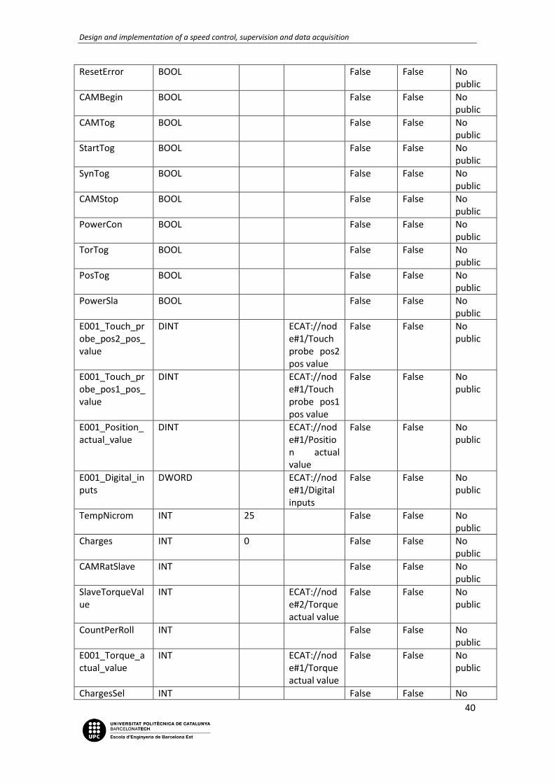
3.5.3 Control’s Logic
Upon, there are the different data types defined in the last chapter, these are all the variables
used in this project. Some of them may not be in use anymore, but are saved for simulation
purposes in the programming phase (E0, E1, E2, etc. and some FB).
The following tables will show all the variables ordered by global and internal, and inside the
internal divided in four groups: Initializing, Common, Quick Guide and MachineProcess.
For these variables, its name, data type, initial value (by default/empty, none), AT or address,
retentive and constant variables, and access or public/comment will be defined.
Global variables
Name Data Type Initial Value
AT Retentive Constant Public
Virtual _sAXIS_REF MC://_MC_AX[0]
False True No public
Slave _sAXIS_REF MC://_MC_AX[2]
False True No public
Conveyor _sAXIS_REF MC://_MC_AX[1]
False True No public

Design and implementation of a speed control, supervision and data acquisition
39
CamProperty0 _sMC_CAM_PROPERTY
False False No public
CamTableQG ARRAY[0..3600] OF _sMC_CAM_REF
False False No public
CAM0 ARRAY[0..36000] OF _sMC_CAM_REF
None False False No public
ProcessCAM ARRAY[0..36000] OF _sMC_CAM_REF
None False False No public
CamNode0 ARRAY[0..4] OF _sMC_CAM_NODE
False False No public
StopTor BOOL False False No public
GearOutSync BOOL False False No public
GearInSync BOOL False False No public
StopSync BOOL False False No public
MachineSlaTog BOOL False False No public
MovePos BOOL False False No public
MoveSync BOOL False False No public
MachineConTog BOOL False False No public
MoveTor BOOL False False No public
RollCharged BOOL False False No public
MasterMove BOOL False False No public
StopProcess BOOL False False No public
OutOfSupplies BOOL False False No public
EndCAM BOOL False False No public
HeatNicrom BOOL False False No public
Synchronized BOOL False False No public
EVOn BOOL False False No public
StartProcess BOOL False False No public
Design and implementation of a speed control, supervision and data acquisition
40
ResetError BOOL False False No public
CAMBegin BOOL False False No public
CAMTog BOOL False False No public
StartTog BOOL False False No public
SynTog BOOL False False No public
CAMStop BOOL False False No public
PowerCon BOOL False False No public
TorTog BOOL False False No public
PosTog BOOL False False No public
PowerSla BOOL False False No public
E001_Touch_probe_pos2_pos_value
DINT ECAT://node#1/Touch probe pos2 pos value
False False No public
E001_Touch_probe_pos1_pos_value
DINT ECAT://node#1/Touch probe pos1 pos value
False False No public
E001_Position_actual_value
DINT ECAT://node#1/Position actual value
False False No public
E001_Digital_inputs
DWORD ECAT://node#1/Digital inputs
False False No public
TempNicrom INT 25 False False No public
Charges INT 0 False False No public
CAMRatSlave INT False False No public
SlaveTorqueValue
INT ECAT://node#2/Torque actual value
False False No public
CountPerRoll INT False False No public
E001_Torque_actual_value
INT ECAT://node#1/Torque actual value
False False No public
ChargesSel INT False False No

Design and implementation of a speed control, supervision and data acquisition
41
public
CountTotal INT False False No public
RatNum INT False False No public
RatDen INT False False No public
AxisSelect INT False False No public
MoveType INT False False No public
AxisPos INT False False No public
ProcessProduction
INT False False No public
DistanceNode2 INT False False No public
CAMRatMaster INT False False No public
PhaseNode2 INT False False No public
PhaseNode1 INT False False No public
DistanceNode1 INT False False No public
TorqueSet LREAL False False No public
CAMSpeed LREAL False False No public
Speed LREAL False False No public
E001_Modes_of_operation_display
SINT ECAT://node#1/Modes of operation display
False False No public
E001_Error_code
WORD ECAT://node#1/Error code
False False No public
E001_Statusword
WORD ECAT://node#1/Statusword
False False No public
E001_Touch_probe_status
WORD ECAT://node#1/Touch probe status
False False No public
Virtual _sAXIS_REF MC://_MC_AX[0]
False True No public
Slave _sAXIS_REF MC://_MC_AX[2]
False True No public

Design and implementation of a speed control, supervision and data acquisition
42
Conveyor _sAXIS_REF MC://_MC_AX[1]
False True No public
CamProperty0 _sMC_CAM_PROPERTY
False False No public
CamTableQG ARRAY[0..3600] OF _sMC_CAM_REF
False False No public
CAM0 ARRAY[0..36000] OF _sMC_CAM_REF
None False False No public
ProcessCAM ARRAY[0..36000] OF _sMC_CAM_REF
None False False No public
CamNode0 ARRAY[0..4] OF _sMC_CAM_NODE
False False No public
StopTor BOOL False False No public
GearOutSync BOOL False False No public
GearInSync BOOL False False No public
StopSync BOOL False False No public
MachineSlaTog BOOL False False No public
MovePos BOOL False False No public
MoveSync BOOL False False No public
MachineConTog BOOL False False No public
MoveTor BOOL False False No public
RollCharged BOOL False False No public
MasterMove BOOL False False No public
StopProcess BOOL False False No public
OutOfSupplies BOOL False False No public
EndCAM BOOL False False No public
HeatNicrom BOOL False False No public
Synchronized BOOL False False No public
EVOn BOOL False False No public

Design and implementation of a speed control, supervision and data acquisition
43
StartProcess BOOL False False No public
ResetError BOOL False False No public
CAMBegin BOOL False False No public
CAMTog BOOL False False No public
StartTog BOOL False False No public
SynTog BOOL False False No public
CAMStop BOOL False False No public
PowerCon BOOL False False No public
TorTog BOOL False False No public
Table 3. Global variables list
Name Data Type Initial Value AT Retentive Constant Comment
HomingConveyor MC_Home False False
HomingSlave MC_Home False False
e0 BOOL False False
Table 4. Initializing internal variables list
Name Data Type
Initial Value
AT Retentive Constant Comment
PowerAxis1 MC_Power False False
PowerAxis2 MC_Power False False
ResetErrorConveyor MC_Reset False False
PowerConveyor MC_Power False False
PowerSlave MC_Power False False
ResetErrorSlave MC_Reset False False
ResetNJError ResetPLCError False False
Table 5. Common internal variables list
Name Data Type Initial Value
AT Retentive Constant Comment
Axis _sAXIS_REF False False
MoveMode _eMC_MOVE_MODE
False False
PositioningMove MC_Move False False
TorqueControl MC_TorqueControl
False False

Design and implementation of a speed control, supervision and data acquisition
44
MoveVelocityTorque
MC_MoveVelocity
False False
TorqueRamp LREAL False False
TorqueSpeed LREAL False False
StopTorque MC_Stop False False
e0 BOOL False False
e1 BOOL False False
e2 BOOL False False
GearInSynchronism
MC_GearIn False False
GearOutSynchronism
MC_GearOut False False
Acceleration LREAL False False
StopSynchronism MC_Stop False False
error BOOL False False
errorid WORD False False
MoveVelocitySync
MC_MoveVelocity
False False
WriteCAMDefinition
BOOL False False
WriteCamDefinitionDone
BOOL False False
GenerateCam MC_GenerateCamTable
False False
Generated BOOL False False
CamIn MC_CamIn False False
MoveVirtualCAM MC_MoveVelocity
False False
CamOut MC_CamOut False False
Insync BOOL False False
Index UINT False False
i0 BOOL False False
i1 BOOL False False
i2 BOOL False False
Table 6. Quick Guide internal variables list
Name Data Type Initial Value
AT Retentive Constant Comment
EmptyRoll BOOL False False
Supply BOOL False False
FindFirstPhotocell
BOOL False False
RollCharges INT False False
FirstPhotocellFound
BOOL False False
SecondPhotocellFound
BOOL False False
CarryingSupplie BOOL False False

Design and implementation of a speed control, supervision and data acquisition
45
sDone
MoveProcessMaster
MC_MoveVelocity False False
TorqueProcessMaster
MC_TorqueControl False False
ProcessSpeed LREAL False False
ProcessCAMIn MC_CamIn False False
EVTime TIME False False
EV1 TON False False
EVlapse TP False False
RollChargesCounter
CTD False False
ProcessCAMOut MC_CamOut False False
StopMoveProcess
BOOL False False
BagsCounter CTU False False
BagCounterPerRoll
CTU False False
ConReady BOOL False False
MoveVelocity BOOL False False
StopMoveProcessMaster
MC_Stop False False
Heat BOOL False False
ClockInc R_TRIG False False
ClockDec R_TRIG False False
EndCAMPulse R_TRIG False False
IgnorePhotocells
BOOL False False
StartHeat BOOL False False
Table 7. Machine process internal variables list
3.5.4 Control’s sequence
As aforementioned, there are two parts in this project, quick guide servomotor and process
machine. Over both, there are an initialization process and common commands that influence
the two parts.
To properly follow all these sections, comments and explanations, the reader should be
switching between PLC chapter 3.5 and HMI chapter 3.6 to follow screen’s refererences, as well
as over buttons, variables and functions.

Design and implementation of a speed control, supervision and data acquisition
46
Initializing – Start
This section is in charge to homing servomotors with photocell’s signal. It happens in two
possible ways: when Start button is pressed or Home button is pressed, the last one being
placed in Selection Screen.
Common – PowerServos
Used in all project to power servos according project’s phase/step.
MachineConTog and MachineSlaTog are placed to ensure the first stop when machine process
begins and the first carry of supplies has to be performed safely. So, when we enter the
machine process, in order to ensure the safety in this first process, the PLC disables both
motors, and can only be reactivated with a sequence that guarantees the operator’s safety.
This will be explained in the CarryingSupplies chapter.

Design and implementation of a speed control, supervision and data acquisition
47
Common – ResetErrors
This section is designed to reset the errors that may occur during any point of guide or process.
Communication errors, excess of speed at servos or any malfunction detected by PLC or
servo’s CU can be acused by this section. The ResetError global viarable is linked to one of
three physical’s button in NA HMI. It will be properly explained in chapter 3.6.

Design and implementation of a speed control, supervision and data acquisition
48
QuickGuide – Positioning
PosTog is only enabled while Positioning page is shown to make this code only executable
when we are on the proper page. Further pages on Quick Guide: Torque Control, Synchronism
and Cam Table are treated in the same way with her “NameToggle” variable designed to be
used only when the page is on HMI’s screen.
When this section is executed, the first line executes a ST inline to associate variables to
correct values in function of the operator’s selection. This ST inline function has become a
really strong tool, specially shining in variable’s declaring, involving only one function with
multiple choices properly assigned in this Structured Text.
In this case, we only use a MC_Move function block for every possible combination between
axis (conveyor or slave) and movement type (relative or absolute).

Design and implementation of a speed control, supervision and data acquisition
49
QuickGuide – TorqueControl
To explain this section properly, MC_TorqueControl has to be explained in a first sequence:
- The MC_TorqueControl instruction controls the output torque of the Servomotor by directly specifying the torque command value.
- Set the target torque in increments of 0.1%. If the second decimal place is specified, it will be rounded off.
- Use MC_Stop instruction to stop the execution of this instruction. - TorqueRamp: Specify the slope from the currently specified command torque until
the target torque is output.

Design and implementation of a speed control, supervision and data acquisition
50
- Velocity (Velocity Limit): Velocity limits the maximum velocity of the axis during torque control. When the axis velocity reaches this velocity limit, the Servo Drive reduces the torque to reduce the axis velocity. The velocity limit function uses the Servo Drive function.
With these directives clarified, the first step in this control function is to define the Torque Ramp and the Velocity Limit. To ensure that there is never a long time ramp, this ramp is always at ¼ speed, becoming in a 4 seconds period for reaching the torque set always.
The velocity limit is defined as half of the speed target to make it easier to detect when the torque control is performing his job; so it can cap the initial speed commanded by servo to ensure the torque set.
Now, the sequence is capable of entering this section through the toggle’s enable, then setting all the variables needed in this screen, TorqueRamp and VelocityLimit. With this done, we enable the Slave’s movement with the proper button and at the same time we enable the torque control over this speed command. Right now, when we apply a force against the direction the Slave is moving, the torque control will begin equally as the ramp previously defined, and it will show the torque (in %) in the screen.
When we want to stop both, movement and torque control, we can hit the Stop Button to accomplish this action; as explained above, MC_Stop will not only stops the movement, but will stops the torque control as well.

Design and implementation of a speed control, supervision and data acquisition
51
QuickGuide – Synchronism

Design and implementation of a speed control, supervision and data acquisition
52
Same as TorqueRamp, Acceleration is defined proportionally to speed, making it 4 seconds to reach target speed.
We define speed one more time, but in this case we only define the master’s speed and by setting the ratio between master and slave, we set the different speeds commanded to slave during the acceleration ramp and the target speed.
So we can do it with the MC_GearOut FB, to desynchronize the slave at a specified deceleration (same as acceleration). If master is stopped while the gear is active, both, master and slave will stop at maximum speed and backwards, and the specified speed will be retaken when Move button is pressed again; so once gear is done (geared), slave move proportionally at master speed, being it at whatever is defined (RatioNumerator/RatioDenominator).
That becomes specially handful when, for isntance, there are a couple of products travelling on a conveyor at a defined speed in function of productions necessities. This products are moved by other servo from conveyor to boxes, and only fixing conveyor’s speed, the slave who push this products to the boxes move proportionally. This can be applied to much more function, most related to pick and place protocols.

Design and implementation of a speed control, supervision and data acquisition
53
QuickGuide – CAM

Design and implementation of a speed control, supervision and data acquisition
54

Design and implementation of a speed control, supervision and data acquisition
55
CAM Table is the evolution of synchronism. Going further than synchronism, that simply multiplies the master’s velocity, CAM Table is able to work every axis independently, avoiding to set a constant ratio between both, and becoming an enclosed flexible relation between two points. In other words, when Master reaches point X1, Slave has to reach the point Y1 at same time, then the same for X2, Y2; X3, Y3, etc. and without the need of being a proportionality between (X1, Y1; X2, Y2) U (X2, Y2; X3, Y3).
Design and implementation of a speed control, supervision and data acquisition
56
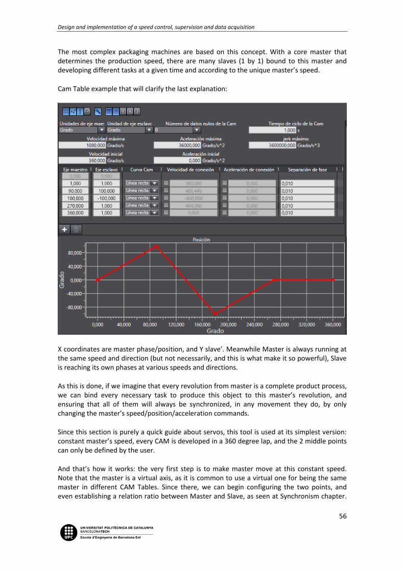
The most complex packaging machines are based on this concept. With a core master that determines the production speed, there are many slaves (1 by 1) bound to this master and developing different tasks at a given time and according to the unique master’s speed.
Cam Table example that will clarify the last explanation:
X coordinates are master phase/position, and Y slave’. Meanwhile Master is always running at the same speed and direction (but not necessarily, and this is what make it so powerful), Slave is reaching its own phases at various speeds and directions.
As this is done, if we imagine that every revolution from master is a complete product process, we can bind every necessary task to produce this object to this master’s revolution, and ensuring that all of them will always be synchronized, in any movement they do, by only changing the master’s speed/position/acceleration commands.
Since this section is purely a quick guide about servos, this tool is used at its simplest version: constant master’s speed, every CAM is developed in a 360 degree lap, and the 2 middle points can only be defined by the user.
And that’s how it works: the very first step is to make master move at this constant speed. Note that the master is a virtual axis, as it is common to use a virtual one for being the same master in different CAM Tables. Since there, we can begin configuring the two points, and even establishing a relation ratio between Master and Slave, as seen at Synchronism chapter.
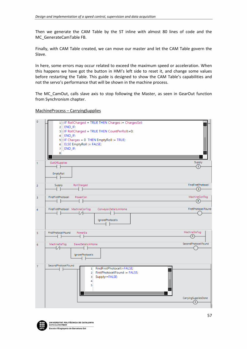
Design and implementation of a speed control, supervision and data acquisition
57
Then we generate the CAM Table by the ST inline with almost 80 lines of code and the MC_GenerateCamTable FB.
Finally, with CAM Table created, we can move our master and let the CAM Table govern the Slave.
In here, some errors may occur related to exceed the maximum speed or acceleration. When this happens we have got the button in HMI’s left side to reset it, and change some values before restarting the Table. This guide is designed to show the CAM Table’s capabilities and not the servo’s performance that will be shown in the machine process.
The MC_CamOut, calls slave axis to stop following the Master, as seen in GearOut function from Synchronism chapter.
MachineProcess – CarryingSupplies

Design and implementation of a speed control, supervision and data acquisition
58
Inside Machine Process, there are two differentiate parts: carrying supplies and process. When we start the machine, the first step to begin the production is to charge the supplies.
Sequence to accomplish: the very first time the machine is powered, the operator has to charge the supplies, or in other words, the roll that will the sheet let go from where packs are produced. To do it safely, there is a sequence to follow, and only in this way servomotors and NiCrom resistances will be powered. First we place the roll in its axis, this axis is associated to conveyor/axis1 in Omron Kit. Since we got the roll properly placed, machine should detect it and its capacity; because the lack of sensors in this Kit, we simulate the sensor that give this signal by a multiple choice menu and a button in the screen (this will be explained in next chapter, HMI). Now, with the roll properly placed, we have to move the sheet across the funnel but making the bag's mark of begin/end being detected by photocell1 that can be found at the funnel's entry, and then we can power the Conveyor.
Making the sheet to travel through the funnel, the sheet becomes a cylinder by overlapping 10 mm of this sheet. When this cylinder comes out by the funnel's exit, the first mark is detected again by the second photocell, making available the option to power the Slave.
The photocells are the associated to every servo, correlating in their names (axis 1, photocell 1) and the bag's mark corresponds to the wheel's white mark in every axis, initially designed and used to home the servos. The method to power every servo when the corresponding photocell detects the mark is via a button in the screen (detailed in next chapter).
Since the sheet is finally placed at its initial position, the last two steps are to set the production speed in bags per minute (BPM) by a screen's menu, and to begin the heating on the resistances in charge to seal the cylinder's nerve and the begin/end of each bag. When the speed is set, we can now give the order to begin the heating process.
In program words, that supposed a challenge to make this process no reversible, and by reach this conjunction of order/sequence process, multiple tests have to be performed. The final result is shown at the above image in different contacts, normally open or closed, it runs as it follows:
The first line, 0, is composed by an ST inline function to pick the HMI's values set by the operator and copying these in other variables that can be worked on. When we press Roll Charged's Button, we set a new variable with the charges number, ready to work and discount one charge or bag for every cycle, and reset Count Per Roll. In the first run, we depend on Empty Roll to let the process begin and to set the coil Supply in line 1 as true and letting the process proceed. Once the machine process is accomplished by the first time, the OutOfSupplies variable will be in charge to permit the carrying supplies to restart.
So now, if the roll is charged, and the supply task is true, we can begin to search the mark in first photocell. To search this mark properly the conveyor must be at stop and free to move to find this white mark, otherwise, if the motor is powered even though it is not moving, we could not move it freely. This is the reason why MachineConTog is set to false, to ensure that the Conveyor is off. This global variable is transmitted at PowerServos section disabling the MC_Power FB.
When we ensure that servo is power OFF, we can move the servo until this mark is reached, and then turn on this first motor. IgnorePhotocells will be discussed later. Now the PLC repeats

Design and implementation of a speed control, supervision and data acquisition
59
the sequence to stop Slave motor and find the mark at second photocell, and then we set CarryingSuppliesDone as true to skip to the next section, designed purely for the repetitive packaging process. At the same time, it resets the variables involved in the supply process to be ready for the next roll change.

Design and implementation of a speed control, supervision and data acquisition
60
MachineProcess - Process

Design and implementation of a speed control, supervision and data acquisition
61
Now that the carrying supplies process is done, PLC will be ready to start executing the core process: packaging. But before, the data acquisition from screen is constantly performed at line 0 by a new ST inline function. This, plus refreshing screen's data set by the operator, simulates the control over the NiCrom resistance's, limiting the temperature at 180 centigrade degrees, reseting the OutOfSupplies variable if the supply is done only when the charges are not equal to zero, and it finally disables the temperature increment by setting the StartHeat as false.

Design and implementation of a speed control, supervision and data acquisition
62
In combination with the specifications given in line 0 and the code in lines 1, 2 and 3 the seal's temperature regulation is performed. It flows to increment or decrement in function if the machine is out of supplies or not, the operator give the order to start the heating and in both cases, by a clock that gives signal every 100 ms to inc/decrease the temp by one degree.
When 180 degrees are reached, PLC is ready to run the next stage that accomplish the servos' movement. Previously, the production's speed is acquired from the HMI at line 5, and this determines the master's movement at a constant speed to fit the production requirements. For this purpose, four speeds production are available: 15, 30, 45 and 60 BPM.
With this target production set, the master can begin to turn; this movement is done by MC_MoveVelocity FB, and this motion block sets a coil to warn that the CAM table can start jumping from line 6 to 8, leaving, in the middle, a line designed to stop the master with this same output (MoveMaster) in serie with the Stop boolean to avoid problems with completely stopping conveyor to all the program. At line 8 we give order to begin the CAM In with Process CAM Table:
Figure 19. Process CAM Table
This table is done with the idea to make the Slave servo move like a linear motor doing a fast approach to sealing/cutting point to create a neat cut. With the linear servo, the slave axis units should be in millimeters as well the units defined previously in Axis properties, but in an essence the configuration would be the same.
The MC_CamIn function will perform periodically while Execute input is true; by every cycle done, EndOfProfile Output will be true for a period and we will associate a variable to it to use it as a counter. This variable, EndCAM, is called in line 9 and it will activate four modules: two increments as counters, one to roll count and another to total count; one decrement to

Design and implementation of a speed control, supervision and data acquisition
63
subtract one charge to the last total, and finally a TempPulse that will be on by 0,5s for each pulse. This last function, TP, works over the electrovalve, controlling the correct weight deposited inside every bag (200 g / 1 s => 100g), and bearing in mind that at full speed the cycle will take 1 second to complete, giving enough time to pour the pellets.
At last line, 10, there are some conditions that, when true, disable de CAM through a MC_CamOut FB, and sets the StopMoveProcess to stop Master, too.
3.6 HMI’s program
3.6.1 Navigation tree
There is a total of ten pages, six of them distributed in two groups; these groups consolidate the two parts of this project.
The image below shows what these pages are and how they are related among them:
Figure 20. Navigation tree
In the chapter 3.6.3 is explained how they work and how you can navigate from one to another.
3.6.2 HMI’s data type
Port (PLC global variable)
Data Type Variable Comment
AxisPos INT AxisPos
AxisSelect INT AxisSelect
CAM0 ARRAY[0..36000] OF _sMC_CAM_REF

Design and implementation of a speed control, supervision and data acquisition
64
CAMBegin BOOL CAMBegin
CamNode0 ARRAY[0..4] OF _sMC_CAM_NODE
CamProperty0 _sMC_CAM_PROPERTY
CAMRatMaster INT CAMRatMaster
CAMRatSlave INT CAMRatSlave
CAMSpeed LREAL CAMSpeed
CAMStop BOOL CAMStop
CamTableQG ARRAY[0..3600] OF _sMC_CAM_REF
CAMTog BOOL CAMTog
Charges INT Charges
ChargesSel INT ChargesSel
Conveyor _sAXIS_REF Eix1_conveyor
ConveyorON BOOL ConveyorON
CountPerRoll INT CountPerRoll
CountTotal INT CountTotal
DistanceNode1 INT DistanceNode1
DistanceNode2 INT DistanceNode2
E001_Digital_inputs DWORD new_Controller_0_E001_Digital_inputs
E001_Error_code WORD new_Controller_0_E001_Error_code
E001_Modes_of_operation_display
SINT new_Controller_0_E001_Modes_of_operation_display
E001_Position_actual_value
DINT E001_Position_actual_value
E001_Statusword WORD new_Controller_0_E001_Statusword
E001_Torque_actual_value
INT E001_Torque_actual_value
E001_Touch_probe_pos1_pos_value
DINT new_Controller_0_E001_Touch_probe_pos1_pos_value
E001_Touch_probe_pos2_pos_value
DINT new_Controller_0_E001_Touch_probe_pos2_pos_value
E001_Touch_probe_status
WORD new_Controller_0_E001_Touch_probe_status
EndCAM BOOL
EVOn BOOL EVOn
GearInSync BOOL GearInSync
GearOutSync BOOL GearOutSync
HeatDone BOOL HeatDone
HeatNicrom BOOL HeatNicrom
HMIProcessProduction LREAL HMIProcessProduction

Design and implementation of a speed control, supervision and data acquisition
65
MachineConTog BOOL MachineConTog
MachineSlaTog BOOL MachineSlaTog
MasterMove BOOL MasterMove
MovePos BOOL MovePos
MoveSync BOOL MoveSync
MoveTor BOOL MoveTor
MoveType INT MoveType
OutOfSupplies BOOL OutOfSupplies
PhaseNode1 INT PhaseNode1
PhaseNode2 INT PhaseNode2
PosTog BOOL PosTog
PowerCon BOOL PowerCon
PowerSla BOOL PowerSla
ProcessCAM ARRAY[0..36000] OF _sMC_CAM_REF
ProcessProduction INT ProcessProduction
RatDen INT RatDen
RatNum INT RatNum
ResetError BOOL ResetError
RollCharged BOOL RollCharged
Slave _sAXIS_REF Eix2_single
SlaveON BOOL SlaveOn
SlaveTorqueValue INT SlaveTorqueValue
Speed LREAL Speed
StartProcess BOOL StartProcess
StartTog BOOL StartTog
StopProcess BOOL StopProcess
StopSync BOOL StopSync
StopTor BOOL StopTor
Synchronized BOOL Synchronized
SynTog BOOL SynTog
TempNicrom INT TempNicrom
TorqueSet LREAL TorqueSet
TorTog BOOL TorTog
Virtual _sAXIS_REF
Table 8. HMI's variables

Design and implementation of a speed control, supervision and data acquisition
66
3.6.3 Screens's design
Start
First page, responsible for introducing the project. This and Selection’s page are the only pages without a back button; the only button is the Start button, which enables the reader to begin the navigation through the HMI.
Selection
When we enter in the selection’s page we find 3 new buttons, Quick-Guide and Machine Process to begin with one of the two parts, and Home, to rehome the servos (remember that when we browse from Start’s Page to Selection’s screen the PLC performs a Homing) which is

Design and implementation of a speed control, supervision and data acquisition
67
handful in order to avoid resetting the whole machine when we switch from quick guide to machine process.
Quick Guide and Machine Process buttons take us to their respective groups or screens, and at the same time they set a global toggle variable to activate the corresponding code sections in PLC.
QuickGuide
A new selection page is displayed, this time facing the Quick Guide options, Positioning, Torque, Synchronism and CAM; and as the previous selection, each button toggles its global variable to run the code according the page displayed, plus showing its page.
Here there’s also a Back button, which is replicated in the subsequent pages and has three functions: show previous page, reset the toggle variable and set the last toggle again, and this case QGTog and SelTog respectively.

Design and implementation of a speed control, supervision and data acquisition
68
Positioning
The first of the four pages dedicated to servo’s function is Positioning. Here, the operator can interact with basic variables to perform a servo’s movement with position target. He can pick which axis to move, which type of movement they will perform, and the position to reach. When all 3 options are picked, the Move button will set a global variable that will enable this movement with its characteristics.
Torque Control
At Torque Control page, there are two magnitudes to be set: constant speed at which servo will move, and max torque. To begin the movement there’s a move button, and since there is

Design and implementation of a speed control, supervision and data acquisition
69
no position limit to stop the movement, there is also a stop button. Here, we will only work with Slave axis, and its torque will be shown at real time.
Synchronism
Here we are going to deal with synchronism functions GearIn and GearOut. We have to set the master’s speed and the ratio between this and its slave, or in other words, when Master completes X laps Slave has to perform Y laps. To start or to stop Master’s movement there are the Move and Stop buttons, with the same behavior as in other pages, and since we got master in move, we can begin the GearIn function with the specified ratio. It performs a ramp to reach the X times Master’s speed, and when it is reached, the Catching Phase lamp at bottom right turns green. That some errors may occur have to be taken into consideration, and those would be caused due to the slave axis being larger than the maximum established, or the acceleration/jerk overcome their maximums.
Cam

Design and implementation of a speed control, supervision and data acquisition
70
Happening exactly the same as in the Synchronism page, Master’s speed and ratio between Master and Slave have to be set by the user at CAM Table page. But here we will also set phase and distance from nodes 1 and 2 to design the table completely. When it is done, first we should do a homing to Slave axis to make it easier to see the action performed; it sets the same variable as the Selection’s page.
Now, CAM In button will make Slave follow it table at Master’s rhythm. That this Master is a virtual axis moving at a constant speed (90 degrees per second) has to be remembered.
It will perform as long as the virtual axis moves, and since it is moving from first task and it is not going to stop, Slave will not do it either unless CAM Out button is hit.

Design and implementation of a speed control, supervision and data acquisition
71
Machine Process
Now we have to go back to Selection’s page to be able to reach to this page through Machine Process Button.
At Roll Charges dropdown menu, we will find 3 options: 10, 50 and 100 charges. When we set one of these options, we can press Roll Charged to begin the supply process explained at last chapter. Following this process, when first photocell finds home’s mark, we can power conveyor motor through its button and we can repeat the process for the second photocell to finally have the machine ready. At this moment, we will set the speed production in this dropdown: 15, 30, 45 and 60 BPM can be set. The last step before starting the machine to produce is to press the Heat button and waiting for the resistances to be properly heated; when these actions are done, the little lamp besides the temp indicator will be displayed as green and Run button will become available.
As Run get toggled, both Master and Slave start their move according the specs explained all along this project to simulate the pellets packaging process. If, for any reason, the process should be stopped, there is a new Stop Button that interacts with both master and CAM and that it would stop both axis.
There are also 3 more lamps that show machine status, green as running, yellow/orange as Out Of Supplies and red as Stop/Error, as well as two label text to show how is the machine performing with roll and total counters.
This page is complemented by next page: Mimic.

Design and implementation of a speed control, supervision and data acquisition
72
Mimic
This page can be reached from any point of the HMI because it is open when one of the three physicals buttons is pressed, the 3 points button located and bottom right:
This page is thought to be a default page while the machine is producing; a fast and visual page to get to know the most important characteristics and details of the machine when the machine is already configured and running.
While the process is drawn, each status lamp is associated besides each component to be easily recognized, clear and fast reading by an easy green-grey color.
Same general Status lamps that were found in last page, Machine Process, are displayed in here. Also, the bags counter can be found here and a new speed display to know at which speed is the machine production at.

Design and implementation of a speed control, supervision and data acquisition
73
Alarms Visor
Same as in the previous page, the Alarms Visor page can be reached from any point of the
HMI, because it is shown when the 2-point button is pressed.
This page will be explained in chapter 3.6.5 Alarm Interface.
3.6.4 Commandment’s design
Different commanders are used in this project. They are listed below.
Buttons
Two sizes of buttons, as well as 2 types, momentary and toggle, all in the same shining grey
color. Most of them interact with 2 or more actions, setting and resetting variables and
showing pages at the same time.
Dropdown menus
Multiple choices menus are used in some pages to easily pick the correct value in some
parameters.

Design and implementation of a speed control, supervision and data acquisition
74
Radio Buttons
This Radio button is used in positioning page to set which type of movement has to be
performed by the axis.
Data Input
This boxes are used in many pages to set multiples variables and magnitudes becoming handy
in many functions and in process machine configuration.
Lamps
Even though it is not a commander, deserves to be mentioned for its information purpose
developed along of the HMI’s program. With text or not, it develops an easy status showing of
many variables and actuators.

Design and implementation of a speed control, supervision and data acquisition
75
3.6.5 Alarms Visor
In Alarms Visor, all Alarms executed since last memory erase are shown. Those are displayed
by date and time order and show its message, priority and group where it belongs.
It develops only an information task to ease operator’s job at finding possible error’s causes
and a data logging of these errors.
By physical HMI’s button, 1-point, a bottom left, we interact with these errors and accuse
them by pressing it. If the problem is properly solved, the error will disappear from PLC or
actuator’s LED.

Design and implementation of a speed control, supervision and data acquisition
76
Chapter 4: Tests and results
4.1. Inputs, outputs and functionality tests and results
In this chapter the behavior between the different variables in every section is analyzed and
traced to see how these interact.
To accomplish this task the Data Trace Function is used, integrated on Sysmac Studio:
To see how every section works, they will be explained one by one again. To properly
understand their function, it is recommended for the reader to revise the corresponding
chapter in PLC's Program explanation (3.5.4 Control's sequence).
4.1.1 Initializing and common
Initializing - Start
The first section deals with the homing of both of the axis. Here it can be appreciated when
the Start Toggle goes True, both Slave and Master begin homing. It never goes off because the
signal from the photocells is not simulated.

Design and implementation of a speed control, supervision and data acquisition
77
Common - Power Servos
A normally closed contact is the condition in both axis powers, to ensure the correct function
in the Machine Process section. In this traces it can be seen how the axis status is the opposite
of the MachineAxisTog corresponding to the MC_Power status.

Design and implementation of a speed control, supervision and data acquisition
78
Common - Reset Errors
Here it can be observed how an error occurs in Slave and it disappears when the ResetError is
set True and the error's cause is solved.
This process is replicated for Conveyor and PLC errors.
4.1.2. Quick Guide
Quick Guide - Positioning
The first of the four sections of functions is positioning. After selecting conveyor as the axis to
move, relative move to perform and 150 degrees as distance to move, we set all this data into
PLC by PosTog set True, the ST inline copy this data, and then by the set of MovePos, the
MC_Move is done by the distance previously set. This can be seen inside the red circle, where
the differential (dy) between the begin and the end of movement is shown.

Design and implementation of a speed control, supervision and data acquisition
79
Quick Guide - Torque Control
With torque control screen showing on HMI (TorTog ON) and speed (360 degrees per second)
and torque target (50 %) set, when MoveTor is true for a little pulse, the movement begins as
shown in Slave Actual Velocity. When this last state goes to 0 degrees per second, it is because
it exists a force who do not permit it to move, but that, at the same time the maximum torque
that servo can develop is controlled (orange trace show it) capping at the 50 % of its nominal
torque.
The reader should remember that while the commanded velocity is 360, the torque control
limits it to the half of it to ensure the torque limit. This process can be observed at the brief
pick after every force applied against servo's movement direction.

Design and implementation of a speed control, supervision and data acquisition
80
Synchronism
These tests will be divided into digital signals and analogs, plus a signal to reference the
analogs. Here, in the digitals trace, we can see how, once inside Synchronism section we first
make the Master move, then we call the MC_GearIn function block and after a delay (4
seconds), the axis are synchronized, 1 by 1 in this example to make a clear explanation and
trace. When GearOut variable is set true for a while, the synchronism disappears and Slave
stops after a 4 second ramp. All this can be better seen with the next graphic:
Once the synchronism is done, we can see how both position lines advance perfectly parallel;
that is because their ratio relation is 1:1. It can also be appreciated the acceleration and
deceleration ramps.

Design and implementation of a speed control, supervision and data acquisition
81
CAM Table
As well as in Synchronism, first the digitals signals will be analyzed. Yellow line shows the time
while we are inside the CAM screen, in blue we can see the pulse to begin the camming, and in
orange the time necessary to create the new CAM Table according to the data input by the
operator. Since this is done, the Slave starts to run the Table and meanwhile it is InSync with
the master, Virtual axis. When the CAMStop signal goes true (last trace), the synchronism ends
and Slave stop instantaneously; this can be appreciated in the analog trace from Virtual and
Slave positions.

Design and implementation of a speed control, supervision and data acquisition
82
With nodes 1 and 2 set as phase 100, distance 150 and phase 200 and distance 300,
respectively, the analog trace is displayed. To become more user-friendly and ease its reading,
the speed is set at 90 degrees per second and the ratio between axis is 1:1.
While virtual axis move at a constant speed without a position target, since the InSync variable
is true, the Slave starts its move according to the Master-Virtual's position, and in this
particular trace, 3 laps are displayed according to the points previously defined.
When the CAM Stop button is true (not shown here), InSync goes False, and Slave stops
automatically to moving.

Design and implementation of a speed control, supervision and data acquisition
83
4.1.3 Process
While OutOfSupplies (brown) is true, the supply process (cyan) is also true. When this
happens, we are able to carry the roll in its place and hit Roll Charged button on Machine
Process screen. When it happens, a chain of events happen, the next turns on, this is
FindFirstPhotocell; then, since Conveyor.Details.InHome is true, meaning that photocell has
found the bag's mark, we can turn on PowerCon (powering conveyor as its name indicates).
Then, dark orange trace goes true, showing that first photocell has been found, and the
carrying supplies process may continue. This time, the sequence is repeated in the second
photocell as it can be observed in the trace, ending with slave powered on.
Since the second photocell mark is found and Slave powered, carrying supplies is done, dark
blue, and it resets all signals involved in the recharge process.

Design and implementation of a speed control, supervision and data acquisition
84
Heating Resistances
Here we can see how, with the start's shot HeatNicrom going true, the temperature increases
from 25 to 180 degrees, and when 180 is reached, HeatDone becomes true. Then, the process
can start, and after a brief delay, we can see how electrovalve (the pink one) goes up and
down for 0,5s every 2 seconds, pouring the 100g of pellets. When the machine goes
OutOfSuplies, resistances begin to cool and the temperature falls as fast as is raised until it
returns to its original point, which is 25 degrees.
Packaging Process
Since the heating is done, process can begin. When RUN button is pressed, cyan, Master
moves until the Stop Process becomes true, and while it is, the process gets frozen at this
point. Since this last variable goes false again, the process is retaken from last point and keeps
it movement until the machine gets out of supplies.
EndCAM takes only 1 ms, and the trace's resolution to fit all the process is 20 seconds; which is
the reason that it appears always as false.

Design and implementation of a speed control, supervision and data acquisition
85
Even if it is hard to see, we can observe how Slave steps up and down the Conveyor trajectory
this will be seen better in the next capture. While MasterMove is true, both conveyor and
slave keeps moving towards the same point, packing a bag in every lap.
Zooming in, how conveyors keeps its movement constant and the Slave goes slow in general
till it reaches a point where speed up can be seen in a better way, suppers the Conveyor
position, and retakes its original velocity. This speed up is to make a neat and clear cut to
separate each bag from the roll, and can be properly appreciated in the following graphic:

Design and implementation of a speed control, supervision and data acquisition
86
While Conveyor stays approximately at the same speed during all the trip, 360 degrees per
second, Slave stays slightly under this speed and makes a sprint for a short time to cut off the
bags.
End Profile
The last test will be focused on the EndCAM, or on the end of profile, events associated. Every
time CAM performs a Table run, a bit is set true for only one period; this is the End Profile, and
it has been associated to EndCAM variable. Since it is only 1 ms long, in normal trace of 20 ms
cannot be seen, so the very last graphic will be a trace with 1 ms resolution to see it.
But for the explanation purpose of this chapter, we must focus on a larger scope of time. This
trace begins its activity when the roll is charged, and then the CountPerRoll is reset and
charges refreshed to 10. The reader should bear in mind that the delays are because NiCrom
resistances have to heat up. When this is done, by every end of profile, a charge is subtracted,
and a count is added to both counters, total and per roll.
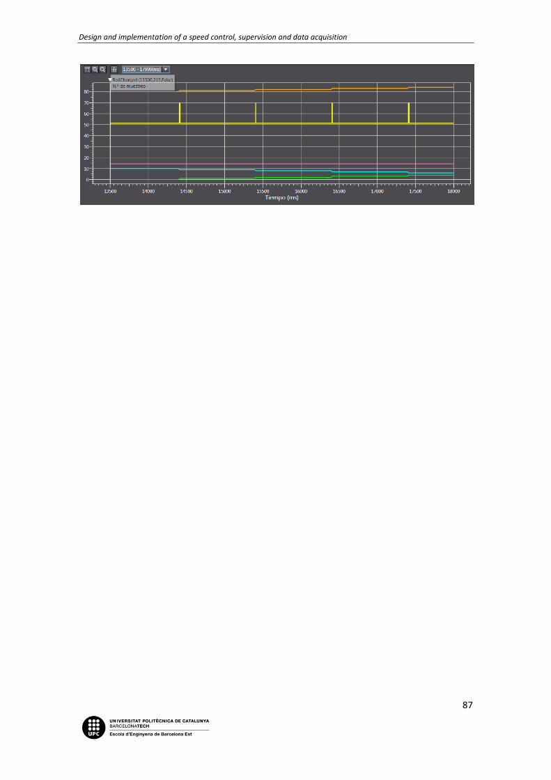
Design and implementation of a speed control, supervision and data acquisition
87

Design and implementation of a speed control, supervision and data acquisition
88
Chapter 5: Standards and regulations
5.1. PLC`s program implementation - IEC 61131
Founded in 1906, the IEC (International Electrotechnical Commission) is known as the world’s leading organization for the preparation and publication of International Standards for all electrical, electronic and related technologies. These are known collectively as “electrotechnology”.
IEC provides a platform to companies, industries and governments for meeting, discussing and developing the International Standards that they require.
All IEC International Standards are fully consensus-based and represent the needs of key stakeholders of every nation participating in IEC work. Every member country, no matter how large or small they are, has one vote and a say in what goes on in the IEC International Standard.
The purpose of the standard IEC is defined and identified in the main characteristics that refer
to the selection and applications of the PLC's control units and its peripherals. It is also in
charge to specify the minimum requirements for features functional conditions of service
issues construction, and general safety tests applicable to PLCs and their peripherals; to define
more used programming languages, the syntactic and semantic rules, the game manual
fundamental tests and means of extension and adaptation equipment. Another of its purpose
is to give to the users a general information and application guidelines and define
communications between PLCs and other systems.
5.1.1. IEC 61131-3
Part 3 of IEC 61131 deals with basic software architecture and programming languages of the control program within PLC. It defines two graphical and two textual programming language standards:
- Ladder diagram (LD), graphical - Function block diagram (FBD), graphical - Structured text (ST), textual - Sequential function chart (SFC), has elements to organize programs for sequential and
parallel control processing.
In this project both ladder and structured text are used, and this third chapter is the one to define the language and functions inside the IDE Sysmac Studio. These points are:
- Data types; defined in chapter 3.5.2. - Variables types, global, local, I/O Mapping, External, temporary; and its attributes
retain, constant and AT.

Design and implementation of a speed control, supervision and data acquisition
89
Figure 21. Internal and external variables
Figure 22. Global variables
- Configuration like resource (CPU, servos), tasks and programs that can be executed once, on a timer, on an event.
Figure 23. Tasks
- Program Organization Unit (POU): functions, standard and customizables; function blocks and programs.

Design and implementation of a speed control, supervision and data acquisition
90
Figure 24. Program Organization Unit
5.2. HMI's Standards - IEC 61310-1
This Standard specifies requirements for visual, acoustic and tactile methods of indicating
safety-related information, at the human-machine interface and to exposed persons. It
specifies a system of colors, safety signs, markings and other warnings, intended to use in the
indication of hazardous situations and health hazards and to meet certain emergencies. It also
specifies ways of coding visual, acoustic and tactile signals for indicators and actuators to
facilitate the safe use and monitoring of the machinery. It includes the following significant
technical changes with respect to the previous edition: Adapted to the basic standards IEC
60073, IEC 60417, ISO 3864-1, ISO 7000 and ISO 7010.

Design and implementation of a speed control, supervision and data acquisition
91
Chapter 6: Conclusions
With every chapter completed and with it, all their parts, with every test done and also with
the results of it properly valued, it is time to ask the throw the final question: does this project
complies with its objective?
To answer this question, the first step is to remember which these objectives were. The first
and main objective was to learn how servomotors work, which are their functions and how are
they able to shine over the traditional motor and their controls, and this has been achieved
completely. Working, programming and even playing with the four main characteristics and
functions of servomotors has made me enjoy and learn all the capabilities that can develop
this little top of motion technology. Through a functional and practical Quick Guide that could
be compared to an instructional training for the operators, every one of these functions
(Positioning, Torque Control, Synchronism and CAM Table) has been worked on and
understood as a generic servomotor, not only Accurax G5 from Omron; this knowledge may be
applied to others as S120 or V90 from Siemens, Kinetix from Rockwell, and furthermore.
On the other hand, there was the machine process project. Again, it did achieve its purpose:
simulated with the Omron's Kit Hardware a functional packaging machine adapted to its
hardware, the software available, and its design. If it is true that programming it, I have learnt
which are the common and usual problems that can develop, I also feel that this is only a very
specific application that servomotors fits; packaging is an excellent servomotor's application,
but dosages are another clear example where the servo's characteristics would master in, and
for sure these are already performing in many kinds of industry, like in the pharma industry.
Strictly speaking, both machine process and servomotors guide have reached their objectives,
(one with a real industry application simulation, and the other with a train to learn how servos
work) the first one deserves the thought of not being as useful as the second. This is due to it
specific target, the simulate of a specific process, that it takes much time in other functions
that are more simple, like temporizers or simply the contacts and coils. It is true that this
knowledge is necessary to design and program a PLC, but this is usually a pretty simple process
that nowadays even a non-graduate person from a "training cycle" (here known as a Cicle
Formatiu or FP) can do it almost with eyes closed. It is a fact that can be observed more and
more in the industry of today. Another reason, it is also a fact what the industry shows us
nowadays, to become successful and necessary, people must master in a very tiny area, a
specific branch of a specific subject. For me, my personal objective is to command in the
servomotors and their special functions, not only the packaging process, although this is a
proper way to master at it, I again found that there are many other distractions to attend than
the pure servomotor function or task.
As an interpretation of my own conclusions, and answering the initial question: the answer
would be yes, I strongly believe that this final grade project has achieved its goal in a successful
way. Maybe the comment of resulting in such a more extensive paper that I first thought
should be made. With this statement, I want the reader to understand ‘extensive’ as a big
number of topics to learn about and to grasp and not as a very lengthy project. All these areas
and various topics have hampered, even more, the learning of the main theme of the project.

Design and implementation of a speed control, supervision and data acquisition
92
Chapter 7: Bibliography consultation
Bossar Packaging S.A (2016). Bossar Packaging - Al frente de la tecnología HFFS. Barberà del
Vallès: Luzerta. http://www.bossar.com/es/
EtherCAT Technology Group (2016). EtherCAT. Nuremberg, Germany: EtherCAT Technology
Group. https://www.ethercat.org/en/technology.html
EtherCAT Technology Group (2016). Why use EtherCAT?. Nuremberg, Germany: EtherCAT
Technology Group. https://www.ethercat.org/en/why_use_ethercat.htm
International Electrotechnical Commission (2007). International Standard. Genove,
Switzerland: International Electrotechnical Commission.
https://webstore.iec.ch/preview/info_iec61310-1%7Bed2.0%7Db.pdf
International Electrotechnical Commission (2016). IEC - About the IEC. Genove, Switzerland:
International Electrotechnical Commission. http://www.iec.ch/about/?ref=menu
International Electrotechnical Commission (2007). IEC 61310-1:2007. Genove, Switzerland:
International Electrotechnical Commission. https://webstore.iec.ch/publication/5263
Omron Corporation (2016). Servo-accionamientos. Barcelona: Omron Europa.
https://industrial.omron.es/es/products/servo-drives
PLC Dev (2005-2016). Step 7 Elementary Data Types. Non specified.
http://www.plcdev.com/step_7_elementary_data_types
Rockwell Automation, Inc. (2016). Ethernet/IP Network. Non specified: Rockwell Automation,
Inc. http://ab.rockwellautomation.com/Networks-and-Communications/Ethernet-IP-Network
R. W. Lewis (18 November 2016). IEC 61131. Non specified: Wikipedia.
https://en.wikipedia.org/wiki/IEC_61131
Volpak S.A.U. (2016). Packging Machines and Solutions for a Range of Industries. Santa
Perpètua de Mogoda: Coesia.
http://www.volpak.com/en/home/industries?package=1370262786950&product=137209040
1858