design and implementation of a query processor for a...
TRANSCRIPT
J. SYSTEMS SOFTWARE 49 1993; 21:49-69
Design and Implementation of a Query Processor for a Trusted Distributed Data Base Management System
Harvey Rubinovitz and Bhavani Thuraisingham The MITRE Corporation, Bedford, Massachusetts
Distributed systems are vital for the efficient process-
ing required in military and commercial applications.
For many of these applications, it is especially impor-
tant that the distributed data base management sys-
tems (DDBMS) operate in a secure manner. For exam-
ple, the DDBMS should allow users, who are cleared
at different security levels access to the data base at
different levels of data sensitivity without compromis-
ing security. A DDBMS with multilevel user/data-
handling capability is called a trusted distributed data
base management system (TDDBMS). This article fo-
cuses on query processing in a TDDBMS. It describes
the security issues, algorithms for query processing,
and design and implementation of a query processor
prototype for a TDDBMS.
1. INTRODUCTION
The rapid growth of the networking and information processing industries has led to the development of distributed data base management system (DDBMS) prototypes and commercial DDBMSs (e.g., [l]). In such a system, the data base is stored in several computers which are interconnected by some com- munication media. The aim of a distributed data base management system is to process and commu- nicate data in an efficient and cost-effective manner. It has been recognized that such distributed systems are vital for the efficient processing required in military as well as commercial applications. For many of these applications, it is especially important that the distributed data base systems should operate in a secure manner. For example, the DDBMS should allow users, who are cleared at different levels, access to the data base at different levels of data sensitivity without compromising security.
Address correspondence to the authors at The MITRE Corpora- tion, Burlington Road, Bedford, ,464 01730.
Much work has been done toward providing multi- level user/data-handling capability in centralized data base management systems, known as trusted data base management systems (TDBMS; e.g., [2-61). In contrast, it is only recently that trusted dis- tributed data base management systems (TDDBMS) have received attention. Thuraisingham [7] discussed multilevel security issues for a DDBMS. In particu- lar, that work illustrated a system architecture for a TDDBMS and described the multilevel security im- pact on data distribution, metadata management, query processing, and transaction management. While Thuraisingham [7] focused on a variety of issues for the design of a TDDBMS, we focus here on just one function of a TDDBMS: this function is query processing. A TDDBMS should ensure that users obtain only responses to their queries at or below their security level. In addition, the distribu- tion of the data should be transparent to the user. That is, the user should query the distributed data base as if it were a centralized system. The dis- tributed query processor (DQP), which is responsi- ble for handling queries, should determine the loca- tions of the various relations involved and transmit the requests to the various sites. The responses obtained from these sites have to be assembled before delivery to the user. In addition, it should be ensured that information above the user’s level is not included in the response.
This article describes the detailed design and im- plementation of a DQP for a TDDBMS. To illus- trate the interactions of the DQP with the other modules of the TDDBMS, we first provide a brief overview of our approach to designing a TDDBMS. Then we describe in detail the design and imple- mentation of the DQP. We focus only on JOIN queries because the JOIN operation is time consum- ing and has been studied extensively for nonsecure
0 Elsevier Science Publishing Co., Inc. 65.5 Avenue of the Americas, New York, NY 10010 0164-1212/93/$6,00
50 J. SYSTEMS SOFIWARE 1993; 21:49-69
DDBMSs [l]. We describe four secure distributed query processing algorithms for the JOIN operation, of which two are static and two are dynamic. We then describe the prototype DQP which implements the two static algorithms. The experiments carried out are then discussed. To our knowledge, this is the first secure DQP prototype to be developed.
It should be noted that some preliminary imple- mentation results on distributed query processing for a TDDBMS have been given elsewhere [S]. In that implementation, only a two-logical-machine/ one-physical-machine architecture for a TDDBMS was considered. Much of the information was hard coded in that implementation, so it was difficult to adapt the architecture to a more general situation. Also, since only one physical machine was used, there was no network communication. In addition, the JOIN algorithms implemented in that effort were not efficient, as all of the fragments were simply moved to the query site responsible for exe- cuting the JOIN. Also, a nonsecure commercial DBMS was used for that implementation. Neverthe- less, that effort gave us some experience on imple- menting query processing algorithms in a TDDBMS. Unlike that effort [B], the implementation described here handles any number of logical machines and has been demonstrated using two physical machines. In addition, the JOIN algorithms use the semi-JOIN operation as the query processing tactic. That is, these algorithms are optimized and are, therefore, more efficient. Finally, we have used a commercially available TDBMS for the prototype. As a result, the implementation described here is more appropriate for a TDDBMS.
The organization of this paper is as follows: sec- tion 2 describes the essential points of our approach to designing a TDDBMS. Secure distributed query processing algorithms are described in section 3. The prototype implementation is described in sec- tion 4. The experiments carried out are discussed in section 5. The paper is concluded in section 6. We assume that the reader is familiar with concepts in
H. Rubinovitz and B. Thuraisingham
DDBMS and TDBMS. Ceri and Pelagetti [l] provide an excellent discussion on DDBMS. A useful start- ing point for concepts in TDBMS is the Air Force Summer Study Report [3].
2. APPROACH TO DESIGNING A TDDBMS
In section 2.1 we describe a system architecture for a TDDBMS. Security policy issues will be discussed in section 2.2. Multilevel data distribution issues will be described in section 2.3.
2.1 System Architecture
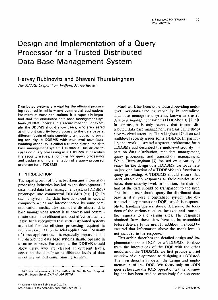
In a TDDBMS, users cleared at different security levels access and share a distributed data base con- sisting of data at different security levels without violating security. The system architecture for a TD- DBMS that we consider in our investigation is shown in Figure 1. Our investigation of the multilevel secu- rity issues for a DDBMS is based on this system architecture.
In this architecture, the TDDBMS consists of several nodes that are interconnected by a trusted network.’ We assume that the nodes are homoge- neous. That is, all of the nodes are designed identi- cally. Each node is capable of handling multilevel data. Each node has a TDBMS which manages the local multilevel data base. Each node also has a distributed processing component called the secure distributed processor GDP). The components of the SDP, shown in Figure 2, are the DQP, the dis- tributed transaction manager (DTM), the distributed metadata manager (DMM), and the distributed con- straint processor (DCP). The DQP is responsible for distributed query processing.’ The DTM is responsi-
’ For a discussion on trusted networks, see Walker [9]. A trusted network is also called a multilevel secure network.
’ This article will focus only on the design and implementation of the DQP.
f Multilevel Database 7 ( Multilevel Database \ ( Multilevel Database ‘\
I Trusted Communication Network
Figure 1. System architecture for a TDDBMS.

Query Processor J. SYSTEMS SOFTWARE 51 1993: 21~49-69
SECURE DISTRIBUTE1 PROCESSOR
ehmrk ma!sc
+
Figure 2. Secure distributed processor.
ble for distributed transaction management.3 The DMM manages the global metadata. The global metadata includes information on the schemas which describe the relations4 in the distributed data base, the way the relations are fragmented, the locations of the fragments, and the constraints enforced.5 The DCP is responsible for handling security constraints during query and update processing.6
The DQP, the DTM, and the DCP communicate with the DMM for the metadata required to carry out their functions. The DCP also communicates with the DQP and the DTM as it processes security constraints during query, update, and transaction execution. In our design of the SDP, we do not have a separate module for update processing. We as- sume that individual update requests are handled by the DQP.’ Update requests specified as part of a transaction are handled by the DTM. Since a trans- action is a series of query and update requests, we
‘A transaction is a program unit that must be executed in its entirety or not executed at all. In a multilevel environment, each transaction executes at a security level. It should be ensured that the actions of higher level transactions do not affect the lower level ones.
4 We assume that the data base is relational. ’ Note that information pertaining to the local data base is
managed by the local TDBMS. ’ Security constraints are rules that assign security levels to the
data. If they are handled during query processing, then the DCP must examine the security constraints and the response assem- bled by the DQP and ensure that the response does not have any information classified above the user’s level. If the constraints are handled during database updates, then the DCP must assign security levels to the data when it is updated. Also, since a transaction consists of a sequence of queries and update requests, security constraints also need to be processed during transaction execution. For a more detailed discussion on security constraints, see references [lo, 111. DCP could also be extended to handle inygrity constraints.
The update operation performed by the DQP is straightfor- ward. A user at level L updates data at level L. In our design of the DQP, we only consider the query operation.
assume that the DQP is invoked by the DTM in order to carry out the individual requests. SDP may be implemented as a set of processes separate from the local TDBMS. Two DMMs (DQPs, DTMs, DCPs) at different nodes communicate in accor- dance with the security policy enforced.
2.2 Security Policy
The security policy for a computing system consists of a set of polices for mandatory security, discre- tionary security, integrity, and authentication among others. Our focus is on a mandatory security policy for a TDDBMS. An effective mandatory security policy for a TDDBMS should ensure that users acquire only information at or below their level.* The basic mandatory security policy for the TD- DBMS that we have considered has the following properties:
1.
2.
3.
4.
5.
Subjects are the active entities (such as processes) and objects are the passive entities (such as files). Subjects and objects are assigned security levels. The set of security levels forms a partially or- dered lattice (e.g., unclassified < confidential < secret < top secret). A subject has read access to an object if the subject’s security level dominates the security level of the object. A subject has write access to an object if the subject’s security level is the security level of the object. (Note that this is a restricted version of the * property of the Bell and Lapadula security policy [ 121.) A subject S, can send a message to another subject S, if the security level of S, dominates (i.e., is greater than or equal to) the level of S,.
In designing a secure system, it may be necessary for additional security policy extensions to be en- forced. Such policy extensions are carried out by trusted subjects.’ That is, the system must ensure that such a subject’s security-critical functions are carried out correctly. In addition, any subject that is privileged to violate the security policy must also be trusted. For example, if a message has to be sent from a secret subject to an unclassified subject, then the secret subject must be trusted.
The security architecture that we consider is shown in Figure 3. We assume that each node has a trusted
’ By a security policy, we mean a mandatory security policy. 9 See the design of the TDBMS [6] for a discussion on security
policy extensions. For a discussion on trusted subjects, see Gasser LI31.
52 J. SYSTEMS SOFIWARE 1993; 21:49-69
H. Rubinovitz and B. Thuraisingham
Applicaticms
TCB at Node 1
Applications . . . . .
TcBat Node 2
Network TCB
Applications
TCB at Node N
Figure 3. Security architecture for a TDDBMS.
computing base (TCB). The TCB is the part of the host that enforces the basic mandatory security pol- icy at that host. The network TCB is responsible for enforcing the network security policy. The TCB hosts various trusted applications, such as a TDBMS and a SDP. Additional security policy extensions may be enforced by these applications, depending on their designs. In our design, the system must ensure that two DMMs (DQPs, DTMs, DCPs) at different nodes can communicate with each other only if they both operate at the same level. Also, additional security policy extensions are enforced by certain modules of the SDP.
Note that in our discussion of security issues for a DDBMS, we do not refer to the level of assurance provided by the system. The levels of assurance provided by computing systems are discussed in the Trusted Computer Systems Evaluation Criteria (TCSEC) [14]. A draft interpretation of the TCSEC for a TDBMS is given in [15]. It appears that criteria for evaluating TDDBMSs will not be available in the near future. The assurance provided by the TD- DBMS will probably depend on the assurance pro- vided by the local hosts and the network.” The assurance provided by the network is determined by the interpretation of the TCSEC for networks given in [16].
2.3 Multilevel Data Distribution
We use a multilevel relational data model at the local and global levels of the TDDBMS. A multilevel relational model is obtained by extending the rela- tional model” with support for multilevel security constructs. In this section we discuss the essential points of the multilevel relational data model being considered and the data distribution issues. A multi- level relational data base consists of a set of multi- level relations. We define a multilevel relation to be a relation in which each tuple is assigned a security
“’ For example, the security policies of the local operating system, local TDBMS, SDP, and the network have to be inte- grated to obtain a security policy for the TDDBMS. Note that very little work has been done on integrating the security policies of different modules.
‘I The relational data model was developed by Codd [17].
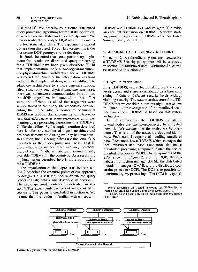
level. We assume that a multilevel relation is decom- posed and stored as single-level relations. That is, all of the tuples of a multilevel relation R classified at level L are stored in a single-level relation at level L. In a multilevel distributed data base, the single- level relations are fragmented and stored at differ- ent sites.
A multilevel distributed data base stored at two sites is illustrated in Figure 4. In this data base, it can be seen that there are two tuples at different security levels with the same primary key. This fea- ture is known as polyinstantiation [6]. In other words, we assume that the SS# together with the security level forms the primary key for the relation EMP. Figure 5 shows the global views that the Unclassified and Secret users have with respect to this distributed data base. These global views are formed by the DQP when a user requests a SELECT-ALL query on the relation EMP. The security policy enforced is such that a user can read any tuple whose security level is dominated by his or her level.
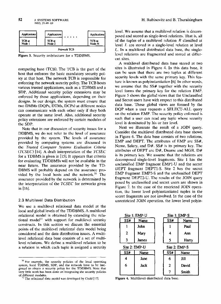
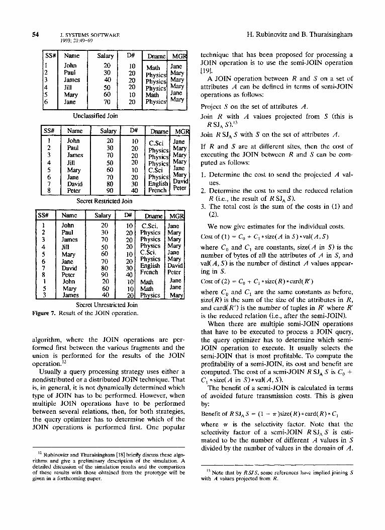
Next we illustrate the result of a JOIN query. Consider the multilevel distributed data base shown in Figure 6. The data base consists of two relations, EMP and DEPT. The attributes of EMP are SS#, Name, Salary, and D#. SS# is its primary key. The attributes of DEPT are D#, Dname and MGR. D# is its primary key. We assume that the relations are decomposed single-level fragments. Site 1 has the unclassified EMP fragment EMPl-U and the secret DEPT fragment DEPTl-S. Site 2 has the secret EMP fragment EMPZS and the unclassified DEPT fragment DEPTZU. The results of the JOIN query posed by unclassified and secret users are shown in Figure 7. In the case of the restricted JOIN opera- tion, the lower level polyinstantiated tuples in the secret fragments are not involved. In the case of the unrestricted JOIN operation, the lower level polyin-
Site 1: EMP-U Site 1: EMP-S
Site 2: EMP-U Site 2: EMP-S
Figure 4. Multilevel distributed data base.

Query Processor J. SYSTEMS SOFIWARE 53 1993; 21:49-69
SS# Name
1 John
t
f Mary James
4 Jane 6 Jack
Unclassified View
Figure 5. Global views.
Name
Paul David James
Barry Jill Smith
Secret View - Lower Level
Polyinstantiated Tuples Removed
SS#
:
z 3 4
4 6 6 7
Name
John Paul
% James Jane Ann HarrY Jack Jill Smith
Secret View - Lower Level Polyinstantiated
EMPl-U
Figure 6. Example distributed data base.
Name SS#!
1 John 2 Paul 3 James 4 Jill
James
David
Pctcr
Tuples Not Removed
SITE 1
DEPTl-S
stantiated tuples are not eliminated. The JOIN query is processed by the DQP. The steps involved in processing the JOIN query will be the subject of section 4.
3. SECURE DISTRIBUTED QUERY -PROCESSING ALGORITHMS
In this section, we describe secure distributed query-processing algorithms for JOIN queries. In section 3.1, we discuss cost computation in dis- tributed query processing. This is necessary to un- derstand the JOIN algorithms. In sections 3.2 and 3.3, we describe secure JOIN algorithms. These al- gorithms handle polyinstantiation, horizontal frag- mentation, and (partial or total) replication. The algorithms that we have designed and implemented are static.
3.1 Cost Computation in Distributed Query Processing
In this section we describe a way of computing costs for executing JOIN queries in distributed query pro- cessing. Our implementation has focused mainly on the JOIN query because the JOIN operation is most time consuming and has been studied extensively for nontrusted DDBMSs. The query considered is of the general form:
R, JOIN Rl.Al=~2.A1~2 JOINRZ,AZ=RXA~~~ JOIN...
JOINR,-,.A~-,=R~.A~-~R~.
There are two ways to process a JOIN operation between two relations. One is called the nondis- tributed JOIN algorithm, where the union of the fragments of each relation is performed before the JOIN operation. The other is called the distributed
54 J. SYSTEMS SOFTWARE 1993; 2149-69
SS# Name
1 John
5 Paul James
4 Jill 5 Mary 6 Jane
SS# Name
SdarY 20 30 40
Z 70
Unclassified Join
D#
10 20
:: 10 20
John Paul James Jill
Jane David Peter
D#t
10 20
;: 10 20 30 40
Secret Restricted Join
iS# Name
John Paul James Jill Mary Jane David Peter John Mary James
Dname MCiI
C.Sci Jane Physics Mary
t
Physics Mary Physics &y C.Sci Physics Mar? English F’“$ French
MGF (2).
MW Mary M=Y Jane Mary David Peter Jane Jane
Marq Secret Unrestricted Join
Figure 7. Result of the JOIN operation.
algorithm, where the JOIN operations are per- formed first between the various fragments and the union is performed for the results of the JOIN operation.‘*
Usually a query processing strategy uses either a nondistributed or a distributed JOIN technique. That is, in general, it is not dynamically determined which type of JOIN has to be performed. However, when multiple JOIN operations have to be performed between several relations, then, for both strategies, the query optimizer has to determine which of the JOIN operations is performed first. One popular
I2 Rubinovitz and Tburaisingham [18] briefly discuss these aigo- rithms and give a preliminary description of the simulation. A detailed discussion of the simulation results and the comparison of these results with those obtained from the prototype will be given in a forthcoming paper.
H. Rubinovitz and B. Thuraisingham
technique that has been proposed for processing a JOIN operation is to use the semi-JOIN operation
D91. A JOIN operation between R and S on a set of
attributes A can be defined in terms of semi-JOIN operations as follows:
Project S on the set of attributes A.
Join R with A values projected from S (this is R SJ, S).13
Join R SJ, S with S on the set of attributes A.
If R and S are at different sites, then the cost of executing the JOIN between R and S can be com- puted as follows:
1. Determine the cost to send the projected A val- ues.
2. Determine the cost to send the reduced relation R (i.e., the result of R SJ, S).
3. The total cost is the sum of the costs in (1) and
We now give estimates for the individual costs.
Costof(1) = C,+ C,*size(A in S)*val(A,S)
where C, and C, are constants, size(A in S) is the number of bytes of all the attributes of A in S, and val( A, S) is the number of distinct A values appear- ing in S.
Cost of (2) = C, + C, *size(R) * card( R’)
where C, and C, are the same constants as before, size(R) is the sum of the size of the attributes in R, and card(R’) is the number of tuples in R’ where R’ is the reduced relation (i.e., after the semi-JOIN).
When there are multiple semi-JOIN operations that have to be executed to process a JOIN query, the query optimizer has to determine which semi- JOIN operation to execute. It usually selects the semi-JOIN that is most profitable. To compute the profitability of a semi-JOIN, its cost and benefit are computed. The cost of a semi-JOIN R SJ, S is C, + C, *size(A in S)*val(A, S).
The benefit of a semi-JOIN is calculated in terms of avoided future transmission costs. This is given by:
Benefit of RSJ,S = (1 - r)size(R)*card(R)*C,
where 7~ is the selectivity factor. Note that the selectivity factor of a semi-JOIN R SJ, S is esti- mated to be the number of different A values in S divided by the number of values in the domain of A.
” Note that by R.S.fS, some references have implied joining S with A values projected from R.
Query Processor J. SYSTEMS SOFTWARE 55 1993; 21:49-69
Profit is set to be (Benefit-Cost). Therefore, the most profitable semi-JOIN among a list of semi- JOINS is the one with the highest profit.
3.2 Nondistributed Join Algorithm
We state an algorithm that statically determines the query execution plan. In this algorithm, we assume that the relations are fragmented and also repli- cated. Furthermore, the tuples are also polyinstanti- ated across security levels and polyinstantiation can occur within as well as across sites.
Suppose a user poses a query at a security level L. The user can issue either a restricted or an unre- stricted request. Let the query be:
R, JOIN RI.AI- KLAIRZ JOINRLT.AZ= R3.AZ R JOIN.. . 3
JOIN Rn-l.An-I=Rn.An-I Rn
In the case of a nondistributed JOIN, the first step is to generate a strategy for performing the union of all the fragments of a relation Ri (1 I i I n). The next step is to determine a strategy for performing the JOIN operation. The third phase is to carry out the execution. That is the algorithm in a three-phase algorithm.
Phase I of the algotithm. During phase 1, the union of the fragments of a relation are performed logically to form a single relation. Therefore, a site has to be selected to perform the UNION operation for each relation. There are several ways to select a site. They include the following:
1. Select the site at which the query was posed. 2. Select the site with the largest number of frag-
ments associated with the relation referenced in the query.
3. Select the site with the largest number of tuples associated with the relation referenced in the
query.
Our algorithm selects the site with the largest num- ber of tuples associated with the relation referenced in the query. Every other fragment not at that site should now be transferred to that site. If the frag- ments are replicated, then we select the primary copy of each fragment and transfer that copy. Note that each relation referenced in the query could be processed at a different site. Since the user is at level L, only the fragments at a level dominated by L are considered in the processing. Before transmit- ting the fragment, any polyinstantiation that is pre- sent locally has to be eliminated if the query is restricted. Furthermore, each tuple in a fragment that is transmitted should tag its security level if the
request is restricted. Next, the selected site will form the logical union of all the fragments. Furthermore, if the query is restricted, then it will eliminate lower level polyinstantiated tuples. It can do this as each tuple will be tagged with a security level. At the end of phase 1, there are n relations, R,, R,, . . . R,, possibly at different sites. Note that in the case of the nondistributed JOIN algorithm, information on polyinstantiation need not be maintained in the data base profiles (e.g., how many tuples are polyinstanti- ated in a fragment, the security levels of the higher level tuples, the sites and fragments that contain the higher level tuples, etc.).
Phase 2 of the algorithm. During phase 2, a JOIN graph is constructed [l]. If there is a JOIN specified between two relations, Ri and Rj, there will be an arc joining the nodes labelled Ri and Rj in the JOIN graph. Next, for every pair of JOINS between Ri and Rj in the JOIN graph, list the semi-JOINS RiSJ Rj and Rj SJ Ri. Let the list of semi-JOINS be LSJ. For each semi-JOIN in the list, compute the cost and benefit of executing this semi-JOIN. Select the semi-JOIN which is most profitable and execute it (by execution we mean logical execution). If the semi-JOIN executed is Ri SJ Rj, then Ri is reduced. From that point onward, the profile for Ri is re- placed by the profile for the reduced relation. In other words, logically Ri is replaced by the reduced relation. (Note that by profile we mean cardinality, size, etc., of a relation.) Next, update the list LSJ by marking the JOIN with the value of the counter (initially, the counter is set to 1). Increment the counter by 1. Recompute the profit for the un- marked semi-JOINS (note that the reduction of the relation during the previous execution could alter the profitability of the semi-JOIN operations com- puted earlier). Select the most profitable semi-JOIN operation and execute it. Repeat this process until all the semi-JOINS have been marked. Finally, de- termine the site at which the JOIN is performed. Note that the final JOIN is done by sending all reduced relations to the site determined. This site is selected depending on the cost of transmission. At this point, do some postoptimization. That is, if the final JOIN is performed at site S, then examine the semi-JOINS to see if any of them reduce relations at site S. If so, eliminate those semi-JOINS from the list.
Phase 3 of the algorithm. Next, physically execute the union of the fragments and then execute the semi-JOINS in the list LXI. The order is determined by the numerical value of the mark associated with

56 J. SYSTEMS SOFIWARE 1993; 21:49-69
H. Rubinovitz and B. Thuraisingham
the semi-JOIN. That is, if semi-JOIN P has mark n, and semi-JOIN Q has mark n2 and if IZ~ I n2, then P is executed before Q. After all the semi-JOINS are processed, transmit the reduced relations to the execution site determined. Perform the JOIN at the execution site. Transfer the result of the JOIN to the site at which the query was posed.
Example. Consider the relations EMP and DEPT. EMP has attributes SS#, Ename, Salary, and D#. The key attribute of EMP is SS#. DEPT has at- tributes Dept#, Dname, and Mgr. The key attribute of DEPT is Dept#. We assume that the cost of transmitting a number is x and the cost of transmit- ting a word is y. Also, SS#, Salary, D#, and Dept# are numbers, while Mgr, Dname, and Ename are words. EMP has three fragments, EMPl-U, EMP2- U, and EMP3-S, at sites S, , S,, and S,, respectively. DEPT has two fragments, DEPTl-U and DEPTZS, at sites S, and S,, respectively. (U is for an unclassi- fied fragment and S for a secret fragment.) EMPl-U is also replicated as REMPl-U at site S,. We as- sume that EMPl-U is the primary copy. The number of tuples in each fragment is given below.
EMPl-U: 20
EMPZU: 30
EMP3-S: 40
DEPTl-U: 20
DEPT2-S: 50
To simplify the discussion in this example, we as- sume that 20% of all tuples in a fragment are polyinstantiated at the higher level. Let a secret user at site S, pose a restricted query to perform the JOIN between EMP and DEPT on the attribute D# of EMP and Dept# of DEPT.
Execution of phase 1. Relation: EMP. Eliminate lower level polyinstantiated tuples if possible. Since EMP3-S and REMPl-U are both at site S,, some of the tuples in REMPl at site S, could be eliminated. The resulting number of tuples in both EMP3-S and REMPl-U is 56 (assuming 20% polyinstantiation). The site to assemble EMP is S, as it has the greatest number of tuples (i.e., EMP3-S and REMPl-U are both at site S,). EMPZU is moved to site S,. The lower level polyinstantiated tuples are removed. The resulting relation EMP is at site S,. The number of tuples in EMP is 80.
Relation: DEPT. Since no two fragments are at one site, no local processing is performed. The site to assemble DEPT is S,. The tuples in DEPTl-U are transmitted to site S,. The lower level polyin-
stantiated tuples are removed during the union op- eration. The resulting relation DEPT is at site S,. The number of tuples in DEPT is 66. We also assume that the total number of Dept# values in the domain is 66.
Execution of phase 2. The semi-JOINS EMP SJ DEPT and DEPT SJ EMP are listed in LSJ. The profit of each semi-JOIN is computed as follows.
We assume that C, = C, = 10, x = 8, and y = 16 (where x is the size of a number and y is the size of a word).
Number of distinct D# values in EMP is 30% of the total = 24. The number of distinct Dept# values in DEPT is 100% of the total (because Dept# is the primary key) = 66.
Cost of EMP SJ DEPT = 10 + 10*66*8 = 5,290
Benefit of EMP SJ DEPT =; - 66/66)*40*80*10 =
Cost of DEPT SJ EMP = 10 + 10*24*8 = 1,930
Benefit of DEPT SJ EMP = (1 - 24/66)*40*66*10 = 16,800
Therefore, DEPT SJ EMP is selected for execution. This will reduce the number of tuples in DEPT to 24. Also, DEPT SJ EMP is marked 1.
Next, the semi-JOIN EMP SJ DEPT is selected for execution and it is marked 2. Note that the algorithm recomputes the profit of this semi-JOIN. This is not necessary as it is the only semi-JOIN left. Also, it can be seen that this semi-JOIN will not reduce the relation EMP. This is because we assume referential integrity (i.e., all the D# values in EMP and also in DEPT), and the relation DEPT has not been reduced since it was reduced earlier by the D# values in EMP. Therefore, the semi-JOIN EMP SJ DEPT is useless. Later we will discuss how useless semi-JOINS can be detected.
Next, the algorithm will determine the site of execution. Now, EMP has 80 tuples and DEPT has 24 tuples each. The cost to transmit EMP to site S2 is 10 + lO* 80 * 40 = 32,010. The cost to transmit

Query Processor
DEPT to site S, is 10 + lO* 24 *40 = 9,610. There- fore, it is more beneficial to perform the JOIN at S,. Therefore, the semi-JOIN EMP SJ DEPT can be removed from the list. The result of the JOIN is transferred from S, to S,.
Execution of phase 3. It is during this phase that the query execution strategy (both for the UNION and JOIN) is carried out. The result of this phase is the response to the query.
An improved algorithm. We saw in the example that a useless semi-JOIN was processed. We now state an improved version of the algorithm given earlier, which avoids processing the useless semi- JOINS.
Let Ri and Rj be the relations which have to be joined. Among the semi-JOIN operations, Ri SJ Rj, Rj SJ Ri, let us assume that Ri SJ Rj is selected first for execution. In the algorithm that we described earlier, the semi-JOIN Ri SJ Rj will be marked. At some later time when Rj SJ R, 1s computed to be the most profitable among the remaining semi-JOINS, executing this semi-JOIN is useful only if Ri has been reduced further since the time it was reduced last by the semi-JOIN Ri SJ Rj. Otherwise the semi- JOIN is useless. Therefore, the algorithm should assign time stamps to each relation which specify the times and also the relations which reduced it.
3.3 Distributed JOIN Algorithm
In this algorithm, we assume that the relations are fragmented and also replicated. Furthermore, the tuples are also polyinstantiated across security levels and polyinstantiation can occur within as well as across sites.
Suppose a user poses a query at a security level L. The user can issue either a restricted or an unre- stricted request. Let the query be: R, JOIN RI.AI=R~.A,~Z JOINRZ.AZ=RXAZ~~ JOIN...
JOIN R Rn-l.An-l=Rn.An-I n.
In the case of a distributed JOIN, the fragments are not merged to form a complete relation. That is, semi-JOIN operations are performed between the fragments in order to reduce them. Finally, the JOIN operation is performed between the reduced fragments. The algorithm has two phases. During the first phase, the query execution strategy is gener- ated. During the second phase, the strategy is physi- cally executed.
Phase 1 of the algorithm. During this phase, the following operations are performed:
1. 2.
3.
4.
5.
6.
J. SYSTEMS SOFTWARE 57 1993; 21:49-69
Construct a JOIN graph (as before). Generate a list of semi-JOINS based on the JOIN graph (see the algorithm for nondistributed JOIN). For each semi-JOIN Ri SJ Rj, do the following operations logically: send the values of the semi- JOIN attributes along with the primary key and its security level from each fragment of Rj to each site which has a fragment of Ri. At a site which has a fragment of Ri, do the following: eliminate the lower level polyinstantiated values from a fragment of Rj just arrived if necessary. Merge the tuples of these fragments of Rj. Re- duce the fragment of Ri at that site by the merged fragment of R,. Estimate the benefit and cost of computing this semi-JOIN. (These compu- tations are performed as before.) Assign numerical values to the semi-JOINS based on their profit (as in the case of the nondis- tributed algorithm). Determine a site to execute the JOIN after all the semi-JOINS have been logically processed. Do some post optimization by eliminating the useless semi-JOINS from the list.
Phase 2 of the algorithm. During this phase, the execution strategy is carried out physically.
Example. We illustrate the algorithm with the same employee-department example discussed for the nondistributed JOIN algorithm in section 3.2. As before, let a secret user pose a restricted query at site S, to perform the JOIN between EMP and DEPT on the attribute D# of EMP and Dept# of DEPT.
Execution of phase 2. The semi-JOINS generated are DEPT SJ EMP and EMP SJ DEPT. We assume that C, = C, = 10, x = 8, and y = 16. The cost of DEPT SJ EMP is computed as follows. The SS# and D# attributes of EMPl-U have to be sent to site S,, SS# and D# attributes of EMP2-U have to be sent to site S,, and SS# and D# attributes of EMP3-S have to be sent to sites S, and S,. Note that the security label of a tuple has to be transmitted also. We assume that the label is an integer. The cost for these transmissions is:
(10 + 10*20*3*8) + (10 + 10*30*3*8)
+ 2*(10 + 10*40*3*8) = 31,240
The benefit of DEPT SJ EMP is computed as fol- lows. Since the tuples in the three EMP fragments

58 J. SYSTEMS SOFTWARE 1993; 21:49-69
will be merged to eliminate the polyinstantiated lower level tuples, the number of remaining tuples in EMP is 80. We need to compute the benefit of the semi-JOINS DEPTl-U SJ EMP and DEPT2-S SJ EMP.
Benefit of the semi-JOIN DEPTl-U SJ EMP = (1 - 7/66)*40* 20* 10 (note that 20% of the tuples in EMPl-U are polyinstantiated and 30% of the D# values in EMP are in DEPT) = 7,200 (approximately).
Benefit of semi-JOIN DEPTZS SJ EMP = (1 - 17/66)*40*50*10 = 15,000 (approximately).
Total benefit = 22,200 (approximately).
Profit of executing DEPT SJ EMP = Benefit - Cost = - 9,000 (approximately).
The cost of EMP SJ DEPT is computed as fol- lows. The Dept# attribute of DEPTl-U has to be sent to sites S, and S,; the Dept# attribute of DEPTZS has to be sent to sites S, and S,. Note that the security label has to be transmitted also. (Note that the EMPl-U fragment is replicated at site S,. However, we have taken the primary copy of the EMPl fragment, which is at site S, in the computation. That is, we do not take advantage of the replication by sending tuples to site S,.) The cost for these transmissions is:
(2*(10 + 10*2*20*8))+ (2*(10 + 10*50*2*8))
= 22,440.
The benefit of EMP SJ DEPT is computed as fol- lows. First the tuples in the two DEPT fragments have to be merged to eliminate the lower level polyinstantiated tuples. The remaining number of tuples in DEPT is 66. Benefit of the three semi-JOIN operations EMPl-U SJ DEPT, EMPZU SJ DEPT, and EMP3-S SJ DEPT is computed as follows:
Benefit of semi-JOIN EMPl-U SJ DEPT = (1 - 1)*40*20*10
Benefit of semi-JOIN EMPZU SJ DEPT = (1 - 1)*40*30*10
Benefit of semi-JOIN EMP3-S SJ DEPT = (1 - 1)*40*40*10
Total benefit = 0
Profit of executing EMP SJ DEPT = Benefit - Cost = - 22,000 (approximately).
H. Rubinovitz and B. Thuraisingham
Therefore, semi-JOIN DEPT SJ EMP is selected for execution first. Then EMP SJ DEPT is selected. Note that EMP SJ DEPT is useless and need not be computed.
Next, the execution site is determined as follows. The fragments EMPl-U, EMP2-U, and EMP3-S re- main the same. The fragment DEPTl-U is reduced to 7 tuples and the fragment DEPT2-S is reduced to 17 tuples, because 20% of the tuples in EMPl-U and EMPZU are polyinstantiated. Furthermore, only 30% of the D# values in DEPT are in EMP. Site 5, has 50 EMP3-S tuples and 20 REMPl-U tuples. Site S, has 17 DEPT2-S tuples and 30 EMP2-U tuples. Site S, has 7 DEPTl-U tuples and 30 EMPl-U tuples. It can be seen that the query execution site will be determined to be S,.
If any of the semi-JOINS between the fragments have to be performed at site S,, then these semi- JOINS can be eliminated from the list. This is the postoptimization process.
Phase 2 of the execution. During this phase, the execution is physically carried out. The result is then transferred from S, to the site at which the query was posed.
Further optimizations. There are several ways to further optimize the distributed JOIN algorithm that we have given here. For example, the techniques described by Yu and Chang [19] can be adapted for secure query processing. That is, the following steps have to be carried out:
1.
2. 3.
4.
5.
4.
Apply a copy selection algorithm to determine which of the copies of the relations or fragments are to be involved in the processing. Discard any useless semi-JOINS. During fragment processing, determine the set of sites where the fragments of a relation have to be sent (i.e., it may not be beneficial to send the fragments to all sites). After each semi-JOIN is executed, recompute the strategy (i.e., repeat the previous steps). After all useful semi-JOINS have been executed, execute the JOIN.
IMPLEMENTATION DESIGN
4.1 Architecture of the DQP
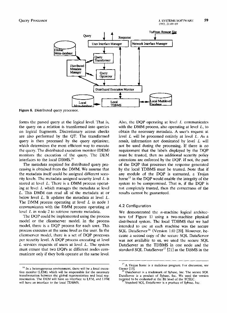
The components of the DQP are shown in Figure 8. The user’s query is parsed by the user interface manager (UIM). The query transformer (QT) trans-
Query Processor J. SYSTEMS SOFIWARE 59 1993; 21:49-69
Figure 8. Distributed query processor.
forms the parsed query at the logical level. That is, the query on a relation is transformed into queries on logical fragments. Discretionary access checks are also performed by the QT. The transformed query is then processed by the query optimizer, which determines the most efficient way to execute the query. The distributed execution monitor (DEM) monitors the execution of the query. The DEM interfaces to the local DBMS.14
The metadata required for distributed query pro- cessing is obtained from the DMM. We assume that the metadata itself could be assigned different secu- rity levels. The metadata assigned security level L is stored at level L. There is a DMM process operat- ing at level L which manages the metadata at level L. This DMM can read all of the metadata at or below level L. It updates the metadata at level L. The DMM process operating at level L in node 1 communicates with the DMM process operating at level L in node 2 to retrieve remote metadata.
The DQP could be implemented using the process model or the clientserver model. In the process model, there is a DQP process for each user. This process executes at the same level as the user. In the clientserver model, there is a set of DQP processes per security level. A DQP process executing at level L services requests of users at level L. The system must ensure that two DQPs at different nodes com- municate only if they both operate at the same level.
l4 In a heterogeneous environment, there will be a local execu- tion monitor (LEM), which will be responsible for the necessary transformation between the global representation and local rep- resentation. The DEM will have an interface to LEM, and LEM will have an interface to the local TDBMS.
Also, the DQP operating at level L communicates with the DMM process, also operating at level L, to obtain the necessary metadata. A user’s request at level L will be processed entirely at level L. As a result, information not dominated by level L will not be used during the processing. If there is no requirement that the labels displayed by the DQP must be trusted, then no additional security policy extensions are enforced by the DQP. If not, the part of the DQP that processes the response generated by the local TDBMS must be trusted. Note that if any module of the DQP is untrusted, a Trojan horse15 in the DQP would enable the integrity of the system to be compromised. That is, if the DQP is not completely trusted, then the correctness of the results cannot be guaranteed.
4.2 Configuration
We demonstrated the n-machine logical architec- ture (of Figure 11 using a two-machine physical distributed system. The local TDBMS that we had intended to use at each machine was the secure SQL DataServer l6 (Version 1.0) [20]. However, be- cause a second copy of the secure SQL DataServer was not available to us, we used the secure SQL DataServer as the TDBMS in one node and the standard SQL DataServer17 [211 as the DBMS in the
I5 A Trojan horse is a malicious program. For discussion, see Gz+;ser [13].
DataServer is a trademark of Sybase, Inc. The secure SQL DataServer is a product of Sybase, Inc. We used the version tarirjeted to be evaluated at the Bl level of the TCSEC.
Standard SQL DataServer is a produce of Sybase, Inc.
60 J. SYSTEMS SOFTWARE 1993; 21:49-69
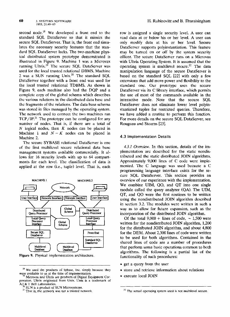
second node.” We developed a front end to the standard SQL DataServer so that it mimics the secure SQL DataServer. That is, the front end simu- lates the necessary security features that the stan- dard SQL DataServer lacks. The two-machine phys- ical distributed system prototype demonstrated is illustrated in Figure 9. Machine 1 was a Microvax running Ultrix. l9 The secure SQL DataServer was used for the local trusted relational DBMS. Machine 2 was a SUN running Unix.‘” The standard SQL DataServer together with a front end was used for the local trusted relational TDBMS. As shown in Figure 9, each machine also had the DQP and a complete copy of the global schema which describes the various relations in the distributed data base and the fragments of the relations. The data base schema was stored in files managed by the operating system. The network used to connect the two machines ran TCP/IP.21 The prototype can be configured for any number of nodes. That is, if there are a total of N logical nodes, then K nodes can be placed in Machine 1 and N - K nodes can be placed in Machine 2.
The secure SYBASE relational DataServer is one of the first multilevel secure relational data base management systems available commercially. It al- lows for 16 security levels with up to 64 compart- ments for each level. The classification of data is applied at the row (i.e., tuple) level. That is, each
H. Rubinovitz and B. Thuraisingham
MAcHlm 1 MACHINE2
P-5 LmJibuted Query Processor 1 Disbibuled
Query proCe.ssor I
Figure 9. Physical implementation architecture.
” We used the products of Sybase, Inc. simply because they we&e available to us at the time of implementation.
Microvax and Ultrix are products of Digital Equipment Cor- poration. Ultrix originated from Unix. Unix is a trademark of AT & T Bell Laboratories.
‘a SUN is a product of SUN Microsystems. *’ That is, the network was not a trusted network.
row is assigned a single security level. A user can read data at or below his or her level. A user can only modify data at his or her level. Secure DataServer supports polyinstantiation. This feature may be turned on or off by the system security officer. The secure DataServer runs on a Microvax with Ultrix Operating System. It is assumed that the operating system is multilevel secure.22 The data manipulation language of the secure DataServer is based on the standard SQL [221 with only a few extensions that add more power and flexibility to the standard one. Our prototype uses the secure DataServer via its C library interface, which permits the use of most of the commands available in the interactive mode. Note that the secure SQL DataServer does not eliminate lower level polyin- stantiated tuples for restricted queries. Therefore, we have added a routine to perform this function. For more details on the secure SQL DataServer, see Rougeau and Stearns [23].
4.3 Implementation Details
4.3.1 Ouemiew. In this section, details of the im- plementation are described for the static nondis- tributed and the static distributed JOIN algorithms. Approximately 9,000 lines of C code were imple- mented. The C language was used because a C programming language interface exists for the se- cure SQL DataServer. This section provides an overview of our experience with the implementation. We combine UIM, QO, and QT into one single module called the query analyzer (QA). The UIM, QT, and QO were the first routines to be written using the nondistributed JOIN algorithm described in section 3.2. The modules were written in such a way as to allow for future expansion, such as the incorporation of the distributed JOIN algorithm.
Of the total 9,000 + lines of code, N 1,500 were written for the nondistributed JOIN algorithm, 1,200 for the distributed JOIN algorithm, and about 4,800 for the DEM. About 2,300 lines of code were written to be used for both algorithms. Contained in the shared lines of code are a number of procedures that perform some basic operations common to both algorithms. The following is a partial list of the functionality of such procedures:
l get a query from the user
l store and retrieve information about relations
l execute local JOIN
22 The actual operating system used is not multilevel secure.
Query Processor J. SYSTEMS SOFTWARE 61 1993: 21:49-69
l move final JOIN relation to user
l read in schema information
All of the procedures in the DEM are used by both algorithms since this module provides the basic op- erations of physical data movement.
In section 4.3.2 we describe the QA. The various configurations for the DQP and the communication configurations are discussed in sections 4.3.3 and 4.3.4, respectively. In section 4.3.5 we describe the DEM. Other issues such as location independence and global schema are discussed in section 4.3.6.
4.3.2 Quer>, analyzer. The QA performs all of the processing of the query before giving it to the DEM for execution. It consists of UIM, QT, and QO. The UIM contains a basic query parser, which performs minimal syntax checking, allowing the user to input various queries. The general syntax of a query is:
(relation1 .attl = relation2.att2, relation3 .att3 = relation4.att4, . . , relation N.att N = relationN + l.attN + 1).
Relationl, relation2, relation3, relation4, relation N, and relation N + 1 are the pairs of relations to per- form the JOINS. Attl, att2, att3, att4, attN, and attN + 1 are the attributes used to perform the JOINS across each pair of relations. At least one condition must be specified to select data from the various relations involved in the query.
An example of the query EMP JOIN DEPT on the attribute d# would be entered by the user as:
EMP.d# = DEPT.d#. The UIM also allows for multiple JOINS across multiple relations to be entered. For example, the queries EMP JOIN DEPT on the attribute d# and DEPT JOIN MANAGER on manager# would be entered by the user as:
EMP.d# = DEF’T.d#, DEPT.manager# = MANAGER.manger#.
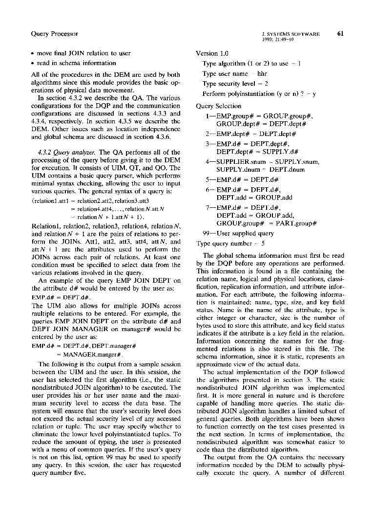
The following is the output from a sample session between the UIM and the user. In this session, the user has selected the first algorithm (i.e., the static nondistributed JOIN algorithm) to be executed. The user provides his or her user name and the maxi- mum security level to access the data base. The system will ensure that the user’s security level does not exceed the actual security level of any accessed relation or tuple. The user may specify whether to eliminate the lower level polyinstantiated tuples. To reduce the amount of typing, the user is presented with a menu of common queries. If the user’s query is not on this list, option 99 may be used to specify any query. In this session, the user has requested query number five.
Version 1 .O
Type algorithm (1 or 2) to use - 1
Type user name - hhr
Type security level - 2
Perform polyinstantiation (y or n> ? - y
Query Selection
I-EMP.group# = GROUP.group#, GROUP.dept# = DEPT.dept#
2-EMP.dept# = DEPT.dept#
3-EMP.d# = DEPT.dept#, DEPT.dept# = SUPPLY.d#
4-SUPPLIER.snum = SUPPLY.snum, SUPPLY.dnum = DEPT.dnum
5-EMP.d# = DEPT.d#
6-EMP.d# = DEPT.d#, DEPT.add = GROUP.add
7-EMP.d# = DEPT.d#, DEPT.add = GROUP.add, GROUP.group# = PART.group#
99-User supplied query
Type query number - 5
The global schema information must first be read by the DQP before any operations are performed. This information is found in a file containing the relation name, logical and physical locations, classi- fication, replication information, and attribute infor- mation. For each attribute, the following informa- tion is maintained: name, type, size, and key field status. Name is the name of the attribute, type is either integer or character, size is the number of bytes used to store this attribute, and key field status indicates if the attribute is a key field in the relation. Information concerning the names for the frag- mented relations is also stored in this file. The schema information, since it is static, represents an approximate view of the actual data.
The actual implementation of the DQP followed the algorithms presented in section 3. The static nondistributed JOIN algorithm was implemented first. It is more general in nature and is therefore capable of handling more queries. The static dis- tributed JOIN algorithm handles a limited subset of general queries. Both algorithms have been shown to function correctly on the test cases presented in the next section. In terms of implementation, the nondistributed algorithm was somewhat easier to code than the distributed algorithm.
The output from the QA contains the necessary information needed by the DEM to actually physi- cally execute the query. A number of different
62 J. SYSTEMS SOFTWARE 1993; 21:49-69
H. Rubinovitz and B. Thuraisingham
schemes are possible to convey this information. The method actually used passes English words (tokens) between the two subsystems. Currently, about twenty commands are supported in the script language. Each command is prefixed with the number of the site where the command is to be executed.
4.3.3 DQP configuration. This configuration sup- ports the client/server paradigm. Each DQP will register its presence to the network as part of its initialization. This allows the physical location of the servers to be transparent to a client located on any node on the network. The server also determines which version of SYBASE (standard or secure) is locally accessible. The DQP will wait until it receives a message from a client at its well-known address. Once a valid message requesting service and provid- ing a limited degree of user authentication is re- ceived, a copy of the server (a child) will start to provide the services to the client. The child process will execute until the client has terminated.
The prototype offers a high degree of flexibility in terms of the number of processes and the data base composition. Any number of attributes, tuples, and relations is supported. No information is hardwired into the system as to the actual view of any relation. The actual prototype running on a two-node system will allow any number of DQPs. Each DQP may be viewed as logically existing on a separate site. This allows for the number of DQPs to exceed the actual physical number of sites. The performance analysis of this system will have to account for differences between logical and physical placement of entities since the communication cost will be different.
The first implemented configuration supported three DQPs placed at logically different sites on two physical machines. Using both the secure and stan- dard versions of SYBASE offers a heterogeneous configuration with respect to both the TDBMSs and the hardware.
4.3.4 Communication configurations. Several dif- ferent communication configurations exist for ex- changing messages between various network en- tities. The actual implemented message-passing technique used Internet IPC sockets under Unix. Three schemes and the one that was selected for the prototype are described below.
Method 1: Single-threaded DQPs. In this configu- ration, one DQP is allowed to run on each node. This configuration is easy to design but has the disadvantage of allowing deadlock situations when multiple users are allowed to simultaneously submit queries. The following is an example of a deadlock
situation. The user interface at site 1 requests DQPl to transfer a relation from site 1 to site 3. Simultane- ously, DQP3 is in the process of transferring a relation to DQPl. At this point, DQP3 is waiting for DQPl and DQPl is waiting for DQP3.
Method 2: Multithreaded DQPs with main memory storage. Access to any DQP to perform some opera- tion will create a private copy (a child process) of the DQP. This method avoids the deadlock problem found in the first configuration. The results of a query will be stored in memory rather than in a file. One copy of a DQP at each site will exist for the duration of a user query. This requires that the port numbers of each communication link between each active set of DQPs be remembered. The active set of DQPs is the total number of DQPs required to complete the user’s query. The disadvantage of this method is the complexity of the communication sys- tem required to create and maintain the links be- tween the active set of DQPs since all query results are passed as messages. Each member of the DQP active set needs to know the others’ port addresses.
Method 3: Multithreaded DQPs with file storage. This method is similar to the second method except that results of a query will be stored in a file rather than in memory. Any number of child processes may share the temporary file rather than using multiple links as is done in the second method.
Comparison of the three methods. Since secure SYBASE will not allow permanent relations to be deleted within a running program because of secu- rity constraints, the first and second methods cannot be used. The third method could be used since each child DQP, once created, is alive for the duration of the user query. The prototype used the third method for communication. Note that it is more complex to maintain temporary relations using secure SYBASE than standard SYBASE.
4.3.5 Distributed execution monitor. The second major component of the DQP physically executes the commands from the first component. This sub- system serves as the actual interface to the SYBASE DataServer. Some of the supported commands are either directed to the SYBASE DataServer for exe- cution or are executed locally. DQP communicates to SYBASE using the DB-Library C interface rou- tines. This library contains routines used to form a bidirectional interface to and from SYBASE. Any interactive SQL may be transferred from a user application program to SYBASE using this inter- face.

Query Processor J. SYSTEMS SOFTWARE 63 1993; 21:4Y-69
Interprocess communication was accomplished by using the Internet naming domain of TCP/IP. There are two ways to do this. (1) Each DQP is assigned a unique communication port address, which the other processes use to communicate with a particular DQP; addresses may be statically assigned to each DQP. (2) The addresses are assigned dynamically. Each DQP writes its unique port address to a file located at each physical site to enable the other processes to communicate with it. The advantage of the first approach is the ease of knowing the address of any DQP. The disadvantage is the failure of the system if some other process uses one of the addresses that is assumed to be owned by this system. Although the second approach is more complex, since it must at execution time obtain a port address and inform the other processes of its new address, it is more flex- ible. Therefore, we implemented the second ap- proach.
Byte ordering is also a related issue to port ad- dressing. Since byte ordering is different on VAX and SUN machines, a common byte ordering must be used. In this case, the various supplied network procedures ensure that all bytes are written accord- ing to the network byte ordering. On the SUNS, these routines are not needed. On some machines, such as a VAX, these routines are used to swap bytes from network ordering to the ordering on the local machine architectures. Byte ordering also plays an important role when transferring data files across the network. The DQPs had to maintain the correct byte ordering when transmitting and receiving data files containing integers.
To operate the standard SQL DataServer in a secure mode, a front-end interface was built. This front end simulates the security features supported by the secure SQL DataServer which are not incor- porated in the standard server. The major feature missing from the standard version is the marking of security labels on all tuples. The front end imple- ments this feature by adding a security label at- tribute to each tuple. This label is analogous to the security label provided by the secure SQL DataServer. The current security level of the user is automatically added to the inserted tuple using the secure SQL DataServer.
5. EXPERIMENTS
This section summarizes the experiments carried out for the secure distributed query-processing algo- rithms presented in section 3. The graphs are given in the Appendix to this paper. Each experiment varied such parameters as number of logical nodes, type of DBMS (secure or standard SQL DataServer),
number of tuples at each security level, percentage of polyinstantiated tuples, and percentage of unique attribute values. The CPU time (in seconds) was measured for each experiment.
Unless otherwise stated, the experiments mapped the three logical sites of the employee-department example described in section 3 onto two physical sites. Logical site 1 was placed on the SUN and logical sites 2 and 3 were placed on the Microvax. The standard version of the SQL DataServer ran on the SUN and the secure version ran on the Mi- crovax. The fifth experiment varied the number of logical sites from 2 through 10, where equal number of logical sites were placed in a machine. The per- formance of the experiments will to some degree be affected by the network transmission delay.
The EMP and DEPT relations (in the example given in section 3) used by the experiments were computer generated rather than from an actual data base. A C program was written that asked the user for the values of various variables, such as percent of polyinstantiation, total number of tuples, number of fragments per relation, and the percentage of unique department numbers. The output from this program is a script file which can be read in by the interactive SQL program supplied by SYBASE to create the actual data base for each experiment. The composi- tion of the computer-generated file may to some degree have affected the overall performance of the experiments. For example, since the EMP file is created in increasing EMP numbers, the time for performing polyinstantiation could be affected.
A brief overview of the six experiments appears below. Note that in this discussion by an algorithm (either nondistributed or distributed) with polyinstantiation we mean that the the lower level polyinstantiated tuples are not included in the com- putation or result. That is, these lower level polyin- stantiated tuples are eliminated in the computation and have no effect. In other words, the JOIN is restricted. By an algorithm (either nondistributed or distributed) without polyinstantiation, we mean that the lower level polyinstantiated tuples are included in the computation or result. That is, these lower level polyinstantiated tuples are not eliminated in the computation and have an effect. In other words, the JOIN is unrestricted.
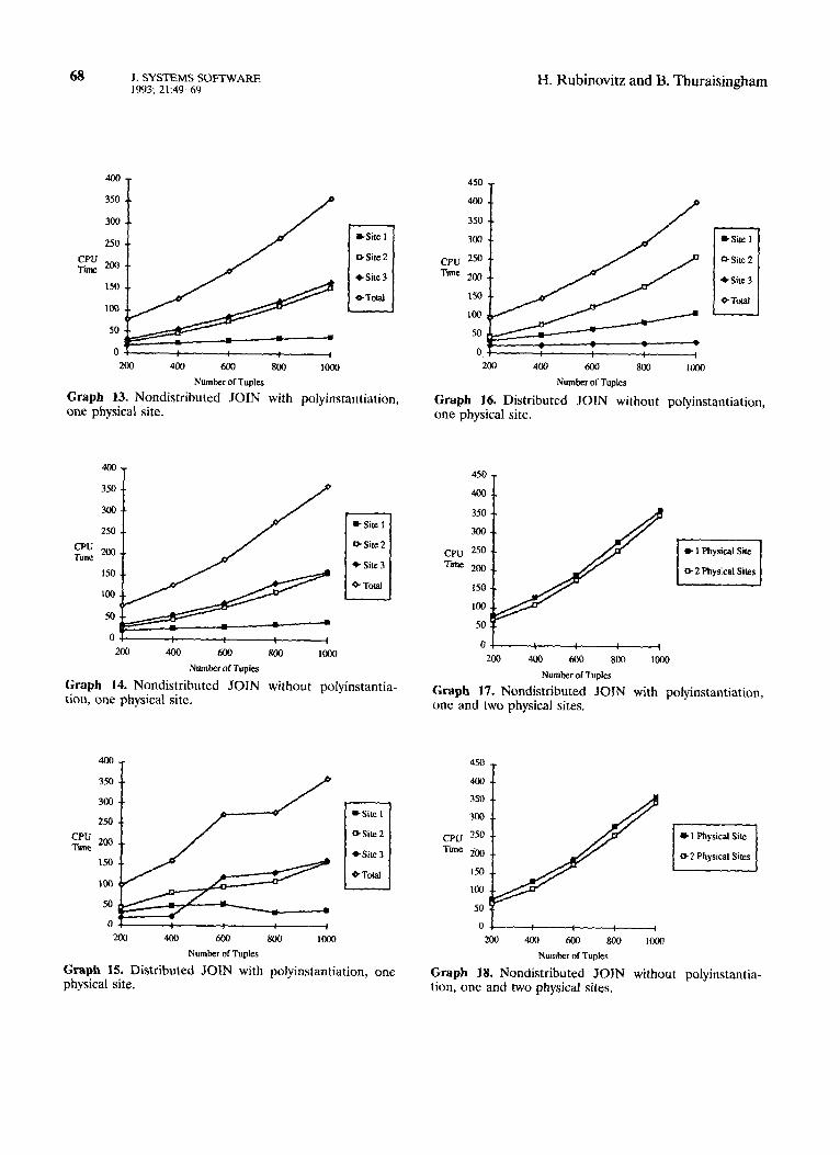
Experiment 1: Nondistributed JOIN Algorithm
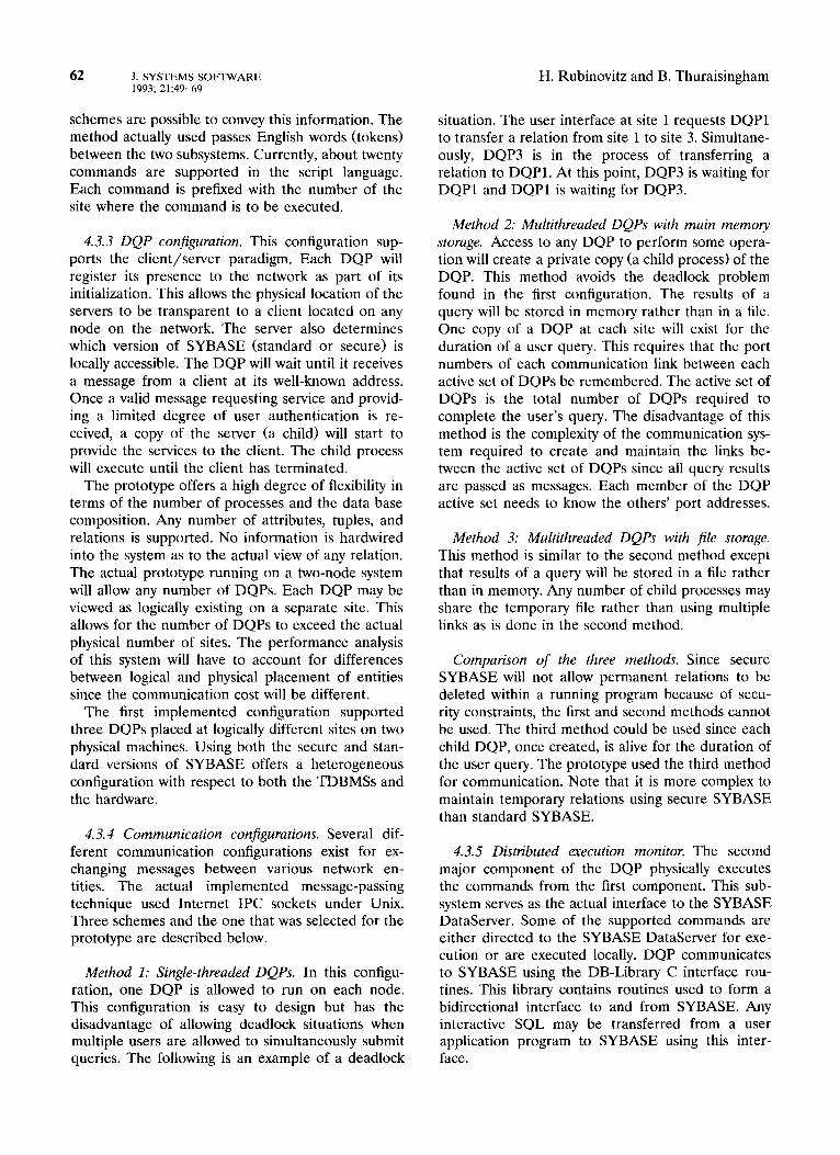
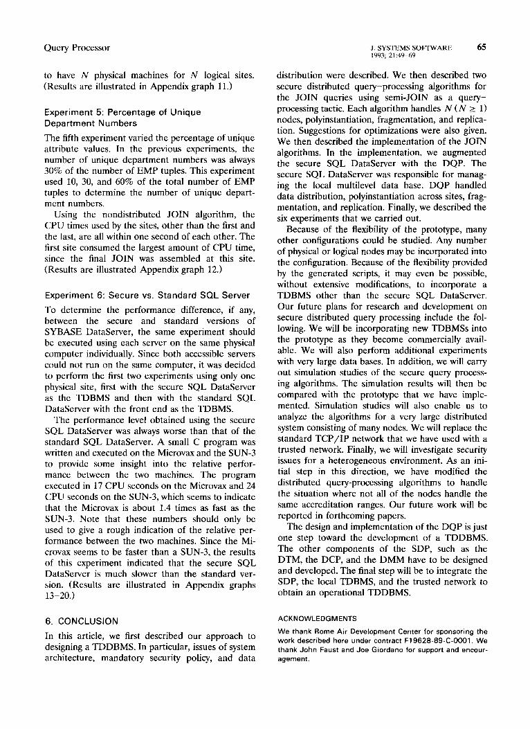
In the first set of experiments, the nondistributed JOIN algorithm was tested with the employee-de- partment data base example described in section 3. In this experiment we assumed that the tuples in each of the fragments varied from 200 to 1000.
64 .I. SYSTEMS SOFTWARE 1993; 21:49-69
The nondistributed JOIN algorithm with polyin- stantiation consumed more time than the nonpolyin- stantiated experiment for the cases of 200 and 400 tuples. In the polyinstantiated experiment, since the number of tuples is reduced before the final JOIN is executed, the final JOIN executes without the addi- tional tuples. To polyinstantiate, a time-consuming sort is executed, after which a sequential search is performed to remove the polyinstantiated tuples from the relation. It is mainly because of this addi- tional data manipulation that the polyinstantiated experiments run slower. For the case of 600 tuples, it seems to cost about the same to either sort and remove the polyinstantiated tuples or perform a JOIN on all the tuples. In the cases of 800 and 1000 tuples, very little time is saved by not polyinstantiat- ing the relation. In both these experiments some time is saved, but because of the number of tuples used, a significant amount of time is not saved. As the number of tuples increases, the number of tu- ples sent across the network would also increase, which would degrade the overall performance. For a large percentage of polyinstantiated tuples, it should be more expensive to execute a query without elimi- nating the lower level polyinstantiated tuples. Based on the results obtained when comparing polyinstan- tiation and nonpolyinstantiation, the performance gain of the polyinstantiation cases is directly related to the percentage of polyinstantiation. The higher the degree of polyinstantiation, the more lower level tuples will be removed before the JOIN operation is executed. (Results are illustrated in Appendix graphs l-3.)
Experiment 2: Distributed JOIN Algorithm
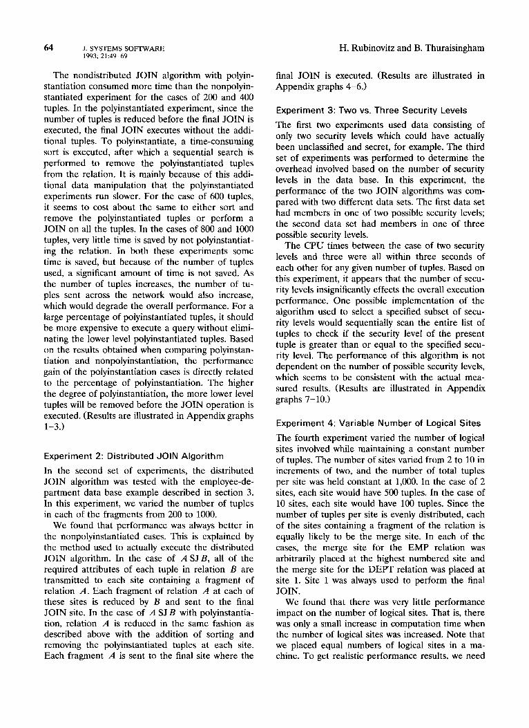
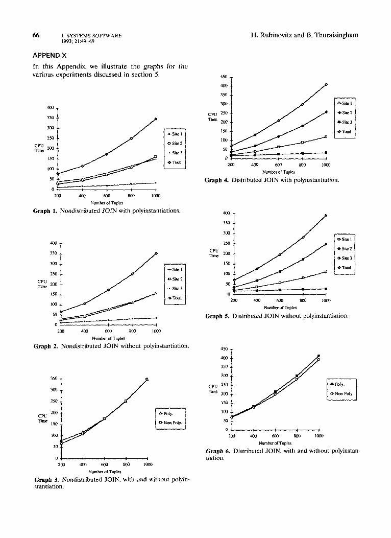
In the second set of experiments, the distributed JOIN algorithm was tested with the employee-de- partment data base example described in section 3. In this experiment, we varied the number of tuples in each of the fragments from 200 to 1000.
We found that performance was always better in the nonpolyinstantiated cases. This is explained by the method used to actually execute the distributed JOIN algorithm. In the case of A SJ B, all of the required attributes of each tuple in relation B are transmitted to each site containing a fragment of relation A. Each fragment of relation A at each of these sites is reduced by B and sent to the final JOIN site. In the case of A SJB with polyinstantia- tion, relation A is reduced in the same fashion as described above with the addition of sorting and removing the polyinstantiated tuples at each site. Each fragment A is sent to the final site where the
H. Rubinovitz and B. Thuraisingham
final JOIN is executed. (Results Appendix graphs 4-6.)
are illustrated in
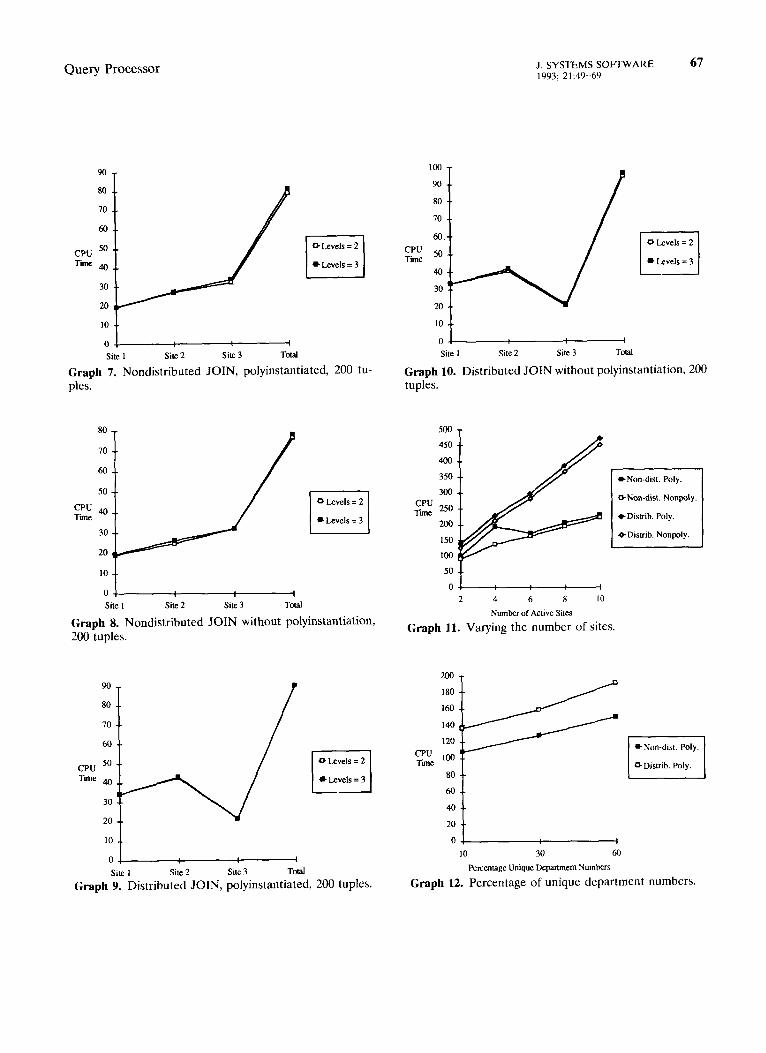
Experiment 3: Two vs. Three Security Levels
The first two experiments used data consisting of only two security levels which could have actually been unclassified and secret, for example. The third set of experiments was performed to determine the overhead involved based on the number of security levels in the data base. In this experiment, the performance of the two JOIN algorithms was com- pared with two different data sets. The first data set had members in one of two possible security levels; the second data set had members in one of three possible security levels.
The CPU times between the case of two security levels and three were all within three seconds of each other for any given number of tuples. Based on this experiment, it appears that the number of secu- rity levels insignificantly effects the overall execution performance. One possible implementation of the algorithm used to select a specified subset of secu- rity levels would sequentially scan the entire list of tuples to check if the security level of the present tuple is greater than or equal to the specified secu- rity level. The performance of this algorithm is not dependent on the number of possible security levels, which seems to be consistent with the actual mea- sured results. (Results are illustrated in Appendix graphs 7-10.)
Experiment 4: Variable Number of Logical Sites
The fourth experiment varied the number of logical sites involved while maintaining a constant number of tuples. The number of sites varied from 2 to 10 in increments of two, and the number of total tuples per site was held constant at 1,000. In the case of 2 sites, each site would have 500 tuples. In the case of 10 sites, each site would have 100 tuples. Since the number of tuples per site is evenly distributed, each of the sites containing a fragment of the relation is equally likely to be the merge site. In each of the cases, the merge site for the EMP relation was arbitrarily placed at the highest numbered site and the merge site for the DEPT relation was placed at site 1. Site 1 was always used to perform the final JOIN.
We found that there was very little performance impact on the number of logical sites. That is, there was only a small increase in computation time when the number of logical sites was increased. Note that we placed equal numbers of logical sites in a ma- chine. To get realistic performance results, we need
Query Processor J. SYSTEMS SOFTWARE 65 1993; 21:49-69
to have N physical machines for N logical sites. (Results are illustrated in Appendix graph 11.)
Experiment 5: Percentage of Unique
Department Numbers
The fifth experiment varied the percentage of unique attribute values. In the previous experiments, the number of unique department numbers was always 30% of the number of EMP tuples. This experiment used 10, 30, and 60% of the total number of EMP tuples to determine the number of unique depart- ment numbers.
Using the nondistributed JOIN algorithm, the CPU times used by the sites, other than the first and the last, are all within one second of each other. The first site consumed the largest amount of CPU time, since the final JOIN was assembled at this site. (Results are illustrated Appendix graph 12.)
Experiment 6: Secure vs. Standard SQL Server
To determine the performance difference, if any, between the secure and standard versions of SYBASE DataServer, the same experiment should be executed using each server on the same physical computer individually. Since both accessible servers could not run on the same computer, it was decided to perform the first two experiments using only one physical site, first with the secure SQL DataServer as the TDBMS and then with the standard SQL DataServer with the front end as the TDBMS.
The performance level obtained using the secure SQL DataServer was always worse than that of the standard SQL DataServer. A small C program was written and executed on the Microvax and the SUN-3 to provide some insight into the relative perfor- mance between the two machines. The program executed in 17 CPU seconds on the Microvax and 24 CPU seconds on the SUN-3, which seems to indicate that the Microvax is about 1.4 times as fast as the SUN-3. Note that these numbers should only be used to give a rough indication of the relative per- formance between the two machines. Since the Mi- crovax seems to be faster than a SUN-3, the results of this experiment indicated that the secure SQL DataServer is much slower than the standard ver- sion. (Results are illustrated in Appendix graphs 13-20.)
6. CONCLUSION
In this article, we first described our approach to designing a TDDBMS. In particular, issues of system architecture, mandatory security policy, and data
distribution were described. We then described two secure distributed query-processing algorithms for the JOIN queries using semi-JOIN as a query- processing tactic. Each algorithm handles N (N 2 1) nodes, polyinstantiation, fragmentation, and replica- tion. Suggestions for optimizations were also given. We then described the implementation of the JOIN algorithms. In the implementation, we augmented the secure SQL DataServer with the DQP. The secure SQL DataServer was responsible for manag- ing the local multilevel data base. DQP handled data distribution, polyinstantiation across sites, frag- mentation, and replication. Finally, we described the six experiments that we carried out.
Because of the flexibility of the prototype, many other configurations could be studied. Any number of physical or logical nodes may be incorporated into the configuration. Because of the flexibility provided by the generated scripts, it may even be possible, without extensive modifications, to incorporate a TDBMS other than the secure SQL DataServer. Our future plans for research and development on secure distributed query processing include the fol- lowing. We will be incorporating new TDBMSs into the prototype as they become commercially avail- able. We will also perform additional experiments with very large data bases. In addition, we will carry out simulation studies of the secure query process- ing algorithms. The simulation results will then be compared with the prototype that we have imple- mented. Simulation studies will also enable us to analyze the algorithms for a very large distributed system consisting of many nodes. We will replace the standard TCP/IP network that we have used with a trusted network. Finally, we will investigate security issues for a heterogeneous environment. As an ini- tial step in this direction, we have modified the distributed query-processing algorithms to handle the situation where not all of the nodes handle the same accreditation ranges. Our future work will be reported in forthcoming papers.
The design and implementation of the DQP is just one step toward the development of a TDDBMS. The other components of the SDP, such as the DTM, the DCP, and the DMM have to be designed and developed. The final step will be to integrate the SDP, the local TDBMS, and the trusted network to obtain an operational TDDBMS.
ACKNOWLEDGMENTS
We thank Rome Air Development Center for sponsoring the work described here under contract F19628-89-C-0001. We thank John Faust and Joe Giordano for support and encour- agement.
66 J. SYSTEMS SOFTWARE 1993; 21:49-69
H. Rubinovitz and B. Thuraisingham
APPENDIX
In this Appendix, we illustrate the graphs fur the various experiments discussed in section 5.
CPU Tn.2
400
350
300
250
2Oa
150
I@3
SO
0
ml 400 600 800 lcm
Number of Tuph
Graph 1. Nondistributed JOIN with polyinstantiations.
450 T
4lm --
350 .-
300 --
CPU 250 .-
200 400 400 800 1000
Number of Tuples
CPU TiZIE
(IS&l
+Site2
*Site3
OTotd
Graph 4. Distributed JOIN with polyinstantiation.
CPU Tii
.=-Site 1
aSite
1
.*-Site 3
.SToCa
400
350
300
250
200
150
100
50
0 400 600 800 loo0
Number of Tuples
Graph 5. Distributed JOlN without polyinstantiation.
CPU Tim
~Sitel
t Site 2
WSile3
*Total
200 400 600 800 loo0
Number of Tuples
Graph 2. Nondistributed JOIN without polyinstantiation.
CPU Time
h- Poly.
= Non Poly.
I
200 400 600 800 1000
Ol 4
200 400 600 800 loo0
Number of Tupks
Graph 3. Nondistributed JOIN, with and without polyin- stantiation.
Number of Tuples
Graph 6. Distributed JOIN, with tiation.
and without polyinstan-
Query Processor J. SYSTEMS SOFIWARE 67 1993: 21:49-69
CPU Tii
OC -I
Site 1 Site2 Site 3 Tocal
Graph 7. Nondistributed JOIN, polyinstantiated, 200 tu- ples.
CPU Tiie
ii,, Site 2 Site 3 TO&d
Graph 8. Nondistributed JOIN without polyinstantiation, 200 tuples.
CPU Tble
0 Levels = 2 II a Levels = 3
Site 1 Site 2 Site 3 Tocal
Graph 9. Distributed JOIN, polyinstantiated, 200 tuples.
CPU Ttie
Site 1 Site 2 Site 3 TOral
Graph 10. Distributed JOIN without polyinstantiation, 200 tuples.
500
450
400
350
300
;;; 250
2M)
150
100
50
0
2 4 6 8 IO
Number of Ache Sites
Graph 11. Varying the number of sites.
-Non-dist. Nonpoly.
ODisuib. Nonpoly.
CPU Tune
40
20 1
Ol IO 30 60
Percentage Unique Department Numbers
Graph 12. Percentage of unique department numbers.
68 J. SYSTEMS SOFTWARE 1993; 21:49-69
350
300
250
2oLl
150
100
50
Ol
200
i
400 600 800 loo0
Number of Tuples
H. Rubinovitz and B. Thuraisingham
450 T
CPU Thne
*Site 1
GSite2
+ Site 3
Graph 13. Nondistributed JOIN with polyinstantiation, one physical site.
Graph 16. Distributed JOIN without polyinstantiation, one physical site.
,Sitel
=!a?2
*-Site3
0 Total
I
2oa 400 600 800 Iwo
Number of Tuples
Graph 14. Nondistributed JOIN without polyinstantia- tion, one physical site.
CPU Tune
*Site1
~Sile 2
+Site 3
*TOM
ml 400 600 800 1000
Number of Tuples
Graph 15. Distributed JOIN with polyinstantiation, one physical site.
CPU TUne
400 600 800 1000
Number of Tuples
*Site 1
aSite 1 hSile3
OTti
450 -
400 . .
3.50 a.
300 -.
CPU 250 . .
& 2 physkal Silts 1 200 400 600 800 1Mx)
Number of Tuples
Graph 17. Nondistributed one and two physical sites.
JOIN with polyinstantiation,
450
400
350
300 i
CPU 250 rnne 200
150
100
SO t
01 200 400 600 800 100~
Number of Tuples
Graph 18. Nondistributed JOIN without polyinstantia- tion, one and two physical sites.

Query Processor
400
350
300
250
200
150
loo
50
200 400 600 800 loo0
Number of Tuplcs
Graph 19. Distributed JOIN with polyinstantiation. one and two physical sites.
CPU Thne
D 2 Physical Sites
200 400 600 800 loo0
Number of Tuples
Graph 20. Distributed JOIN without polyinstantiation, one and two physical sites.
REFERENCES
1.
2.
3.
4.
5.
S. Ceri and G. Pelagetti, Distributed Databases, Princi- ples and Systems, McGraw Hill, New York, 1984. T. Hinke and M. Schaefer, Secure Data Management System, RADC-TR-75-266, System Development Cor- poration, 1975. Air Force Studies Board, Committee on Multilevel Data Management Security, Multileuel Data Manage- ment Security, National Academy Press, 1983. R. Graubart, The integrity lock approach to secure database management, in Proceedings of the 1984 IEEE Symposium on Security and Privacy, Oakland, Califor- nia, 1984. D. E. Denning, et al., A multilevel relational data model, in Proceedings of the IEEE Symposium on Secu- rity and Prinacy, Oakland, California, 1987.
6.
7.
8.
9.
10.
11.
12. 13.
14.
15.
16.
17.
18.
19.
20. 21. 22.
23.
24.
J. SYSTEMS SOFIWARE 69 1993; 21:49-69
P. Stachour and M. B. Thuraisingham, Design of LDV -A Multilevel Secure Database Management System, IEEE Trans. kkowl. Data Eng. 2 (1990). B. Thuraisingham, Multilevel Security Issues in Dis- tributed Database Management Systems, MTP-297, The MITRE Corporation, 1990. B. Thuraisingham and A. Kamon, Secure query pro- cessing in distributed database management systems, in Proceedings of the 6th Computer Security Applica- tions Conference, Tucson, Arizona, 1990. S. Walker, Network security overview, in Proceedings of the 1985 IEEE Symposium on Security and Priuacy, Oakland, California, 1985. P. Dwyer, G. Jelatis, and B. Thuraisingham, Multilevel Security for Database Management Systems, Comp. Sec. 6 (1987). M. B. Thuraisingham, Security Checking in Relational Database Management Systems Augmented With In- ference Engines, Comp. Secur. 6 (1987). Bell and Lapadula, 1975. M. Gasser, Building a Secure Computer System, Van Nostrand, New York, 1988. Trusted Computer Systems Evaluation Criteria, De- partment of Defense Document 5200.28-STD, 1985. Trusted Database Interpretation, Department of De- fense Document, draft, 1989. Trusted Network Interpretation, Department of De- fense Document, draft, 1987. E. F. Codd, A Relational Model of Data for Large Shared Data Banks, Commun. ACM 13, 377-387 (1970). H. Rubinovitz and B. Thuraisingham, Implementation and, simulation of secure distributed query processing algorithms, in Proceedings of the Summer Computer Simulation Conference, Baltimore, Maryland, 1991. C. T. Yu and C. C. Chang, A distributed query pro- cessing strategy, in Proceedings of the ACM SIGMOD Conference, 1983. Secure SQL DataServer, Sybase Inc., 1989. Commercial SYBASE DataSeruer, Sybase Inc., 1989. Structured Query Language, American National Stan- dards Institute, 1988. P. Rougeau and E. Stearns, The SYBASE secure database server: A solution to the multilevel secure DBMS problem, in Proceedings of the 10th National Computer Security Conference, Baltimore, Maryland, 1987. N. Goodman, et al., Query Processing in SDDl: A System for Distributed Databases, ACM TODS 6 (1981).