design and implementation of a prototype vehicle location
TRANSCRIPT

Abstract—This work presents the design and implementation
process of a highly technological and small size device, based on
vehicle location and control of various vehicle parameters. The
proposed prototype is composed of six blocks between the taking
part of the decisions to be executed by a relay system to the
devices to be controlled in the vehicle, passing also by the
acquisition of the GPS signals of the satellites in Orbit, also the
communication system for sending and receiving phone calls and
SMS through the Android application, finally, the power supply
and backup system. The implementation process and functional
tests show the applicability of the prototype thus obtaining a high
technology system and small size.
Index Terms—Vehicle safety; Open-source; Global Positioning
System; Global System for Mobile communications; Near Field
Communication; Android; Arduino.
I. INTRODUCTION
igh delinquency rate in Ecuador today, coupled with the
high cost of existing security systems, mean that vehicle
owners do not opt for smart devices to protect them, making
them easy targets for criminals, It is worth noting that
according to the latest study carried out by CEDATOS in
2011, which shows an increase in crime in Ecuador and
indicates that 65% of the population has been victimized or
has a family member who has been victim of a crime Criminal
[1].
On the other hand, vehicle owners only prefer to opt for
economical common alarm systems, which provide a
minimum degree of safety and also do not offer control of the
vehicle, which is not enough for a country with a high degree
of delinquency and theft of vehicles, which is why we have
opted for the design of a prototype vehicle location and
security system with the purpose of eradicating vehicle theft
and express abductions, if in some unexpected situation a
mishap occurred and we wanted know the exact location of
the vehicle or otherwise have a control of the ignition or the
insurance of the doors, the system must allow to know and
control various parameters of the vehicle remotely, for it uses
modern technologies such as GPS, GSM and NFC, in order to
obtain a highly technological system and with the benefit of
being economical compared to other similar systems.
II. DESIGN OF PROTOTYPE
The best way to eradicate the large amount of vehicle theft
and loss of life caused by express abductions is by helping to
inform the vehicle user of an unexpected situation where
timely care is required, thus avoiding any human tragedy or
material, all this by means of alerts and telephone calls to an
emergency number. On the other hand, to prevent the offender
from stealing the vehicle, it is essential to incorporate an
ignition control system, thus blocking the engine starting
functions; Finally, to help inform the exact location of the
vehicle within the Ecuadorian territory, it is essential to place
a modern vehicular localization system.
As mentioned before, it has been proposed to develop a
prototype that allows the location of the vehicle based on the
implementation of a GPS module on board the vehicle, also
the prototype will allow the authorization of ignition of the
vehicle based on the reading of MIFARE tags through an NFC
reader, on the other hand, will implement a panic button that
allows sending an SMS to an emergency number, reporting an
emergency situation, then make a phone call allowing the
emergency smartphone to listen to the conversation that takes
place in the Interior of the vehicle, with the possibility of
recording the audio automatically; finally, an Android
application will be designed to allow the control of all the
features offered by the prototype, with the possibility of
registering the owner of the vehicle to the prototype based on
the cell number, this is done to prevent others from doing use
of the application and in this way commit some criminal fact.
Design and implementation of a prototype
vehicle location and security system with GPS
and GSM communication, based on hardware
and free software
David Guerra Author, Omar Oña Director. Faculty of Engineering in Applied Sciences, Technical University of the North
Ibarra, Ecuador [email protected], [email protected]
H

Fig. 1. General block diagram of the Vehicle Location and Safety System
prototype.
Figure 1 shows the general block diagram of the prototype,
which is made up of the Control System block, which is in
charge of governing the entire prototype and where all the
communication modules are interconnected, as well is made
up of the Security System block, which is responsible for
complying with the actions that are determined in the Control
System, this block also interacts directly with the vehicle's
own devices, such as the gas pump and the central lock of
doors; on the other hand there is the GSM Communication
System block, which allows the transport of requests and
responses generated both by the Android application as well as
by the Control System; There is also the Location System
block that is responsible for capturing the GPS signals sent by
satellites in orbit, and then send them to the Control System,
processing them and converting them to a predefined format;
Finally, the block of Power System that is responsible for
supplying the necessary voltage to each of the devices and
modules that make up the prototype.
A. Control System
The main element of the Control System is the electronic
development board Arduino Mega 2560, which consists of all
the pins and communication protocols necessary for the
interconnection of each of the devices that make up the entire
prototype.
Fig. 2. Arduino Mega 2560.
Table I allows to observe the technical specifications of the
electronic board Arduino Mega 2560 [2], where the following
is the characteristics used for the development of the
prototype:
It has four UART ports that serve as communication
protocol for GPS and GSM modules.
It provides 54 digital I / O, which allows to connect the
different devices, such as the panic button, relay
connection outputs for the gasoline pump, electric locks,
among others; Providing scalability to adapt more devices
if necessary without any problems.
It has SPI communication, which allows the connection of
the NFC module that is one that allows reading the
MIFARE tags that authorize the ignition of the vehicle.
It incorporates EEPROM memory, which is essential in
the development of this project, since in this memory
important data of the state of the vehicle are kept.
B. Security System
The Security System has as objective the fulfillment of the
actions that in the Control System are determined, these
actions are the following:
Carry out the readings through the NFC reader module of
the MIFARE identification cards or key chains delivered
to the user of the vehicle.
Always feel the panic button, this will be operated by the
user of the vehicle when there is an emergency situation.
Carry out actions of locking or unlocking the petrol pump,
to authorize or not to activate the vehicle.
Activate or deactivate the electric door locks.
Issue on the base of the buzzer the informational sounds
of the state of the vehicle.
Carry out control of the vehicle contact system, to be later
controlled by the prototype Control System.
TABLE I
Technical specifications Arduino Mega 2560
Characteristic Detail
Microcontroller
Operating Voltage
ATmega2560
5V
Input voltage (recommended) 7-12V
E/S Digital Pin 54 (15 PWM out)
Analog input pins 16
DC current for E/S pin 20 mA DC current for 3,3V pin 50 mA
Flash memory 256 KB, 8 KB used by the
bootloader SRAM 8 KB
EEPROM 4 KB
Clock 16 MHz Length 101.52 mm
Width 53.3 mm

Fig. 3. Block diagram of the Security System.
Figure 3 shows how the Security System is formed, it
should be emphasized that it consists of two large sets, which
are the Shield Interface board and the NFC Reader; in which
each set consists of several blocks which are designed
separately to form the entire system.
On the one hand, there is the NFC module which is
responsible for reading the MIFARE ID cards or key chains
delivered to the user, and then authorize or not the vehicle
ignition.
Fig. 4. NFC PN532 module.
Figure 4 shows the physical form of the NFC module
PN532, which consists of a DIP switch selector of the
communication protocol to be used, for this project will be
made use of the SPI protocol, which is made up of the MOSI,
MISO, SCK and SS [3].
TABLE II
Technical specifications NFC PN532 module
Characteristic Detail
Communication I2C, SPI y HSU (High Speed
UART)
Supply voltage 3,3v – SPI 5V – I2C y UART
RFID modes Reading/writing
Mifare 1k, 4k, Ultralight, y DesFire
Antenna PCB incorporated, 5-7cm of
communication distance Power Consumption Standby: 100mA
Reading/writing: 120mA
Size 43mm*41mm*4mm
Table II allows to observe the specifications of the
communication module NFC PN532, where it is possible to
emphasize that it has a small size, easy integration thanks to
the protocols I2C, SPI and HSU that provides, on the other
hand, it allows the reading and writing of tags with MIFARE
technology, an important feature given that thanks to this it is
possible to encrypt the tags with security keys that prevent the
cloning of them.
On the other hand, is the Shield Interface board, which is
one of the most important stages in the development of this
project, because it is in charge of allowing the communication
of the different modules that make up the prototype, which in
this case are the panic button, gasoline pump, central door
lock module of the vehicle, vehicle contact signal, buzzer, and
NFC module power.
One of the blocks that make up the Shield Interface board is
the 3.3V voltage regulator circuit, which is responsible for
providing the necessary voltage and current to the GPS and
NFC modules.
Fig. 5. Electrical diagram of the 3.3V voltage regulator circuit.
Figure 5 shows the electrical diagram that is mainly formed
by the integrated circuit LM317t [4] which, by calculating two
resistors, it is possible to obtain a fixed output voltage, which
in this case will be 3.3v, having as 12V input voltage obtained
directly from the vehicle's main battery.
To calculate the resistances, R1 = 220Ω, Vout = 3.3V was
used as the input data, then replacing this data in equation 1
can obtain the value R2.
𝑅2 = (𝑅1
1,25) (𝑉𝑜𝑢𝑡 − 1,25) (1)
After replacing data, the value of R2 = 360.8Ω is finally
obtained for design purposes, but for commercial purposes the
value of 390Ω will be used. In addition, it is necessary to
calculate the power value dissipated by each of the resistors,
then proceed to make the corresponding similar calculation for
R1 and R2, using equation 2:
𝑃(𝑅1) = (𝑉𝑅1)2
𝑅1 (2)
Finally, we have for R1 = 7mW and for R2 = 11.67mW,
concluding that the resistance and power values to be used are
for R1 = 220Ω to 1 / 4W, and for R2 = 390Ω to 1 / 4W.
Another block that forms the shield Shield Interface is the
relay control circuit for the door locks, which allows the
activation of the relay that will allow the conduction of a
ground signal, this will allow the action of opening or closing

doors according to the case, since two similar circuits are
required.
Fig. 6. Relay control circuit for vehicle door locks.
To achieve this, it is necessary to use a transistor to amplify
the current provided by the Arduino Mega 2560 digital pins,
which are 20mA, which is not sufficient since a common relay
can be activated normally with a current of between 50mA
and 150mA measured in a practical way. In addition, it is also
necessary to perform the calculation of the basic resistance,
which is calculated with equation 3.
𝑅𝑏 = (𝑉𝑐𝑐 − 𝑉𝑏𝑒) ∗ 𝐻𝑓𝑒
𝐼𝑐 (3)
Taking values Vcc = 5V, Vbe = 0.7V, Hfe = 30 and Ic =
70mA and replacing the values in the equation, we finally
have the value of Rb = 1842Ω for design purposes, but for
commercial purposes it is used The value of 2.2kΩ. It is also
necessary to use a mass resistance, which is recommended to
be of a value large enough to not alter the calculation of the
base resistance, then the value of Rmasa = 47kΩ. Finally, as
previously done, it is necessary to calculate the power value
dissipated by each of the resistors, for this use is made of
equation 4, which serves both Rb and Rmasa.
𝑃(𝑅𝑏) = (𝑉𝑅𝑏)2
𝑅𝑏 (4)
The value of the voltage for the base resistor is 𝑉𝑅𝑏 = 𝑉𝑐𝑐 −𝑉𝑏𝑒 = 5𝑉 − 0,7𝑉 = 4,3𝑉, and for the ground resistance is
𝑉𝑅𝑏 = 𝑉𝑏𝑒 = 0,7𝑉, now replacing these values in equation 4,
𝑃(𝑅𝑏) = 10,03𝑚𝑊 and 𝑃(𝑅𝑚𝑎𝑠𝑎) = 10,425µ𝑊; Finally
concluding that the resistance and power values to be used are,
for Rb = 2.2kΩ to 1 / 4W, and for Rmasa = 47kΩ to 1 / 4W.
A block similar to the one above, is the one that allows
controlling the relay that will trigger the operation of the
gasoline pump, in the event that the vehicle ignition is
authorized, the relay control circuit is shown in figure 7, this
to unlike the previous one, it allows the activation of
automotive relays, as it is in this case, since for the actuation
of the same it is necessary a current of around 135mA
measured in a practical way.
Fig. 7. Relay control circuit using an NPN transistor TIP31C.
In order to achieve such a drive current, it is necessary to
use an amplifier transistor, in this case it is the TIP31C, since
it provides a maximum collector current of up to 3A [5], now
similar to the previous circuit, it is necessary to calculate the
resistance of both base and mass, to speed up the calculations
it is necessary to mention that equations 3 and 4 above were
used; Where we have as data that Vcc = 5V, Vbe = 0.7V, Hfe
= 25 and Ic = 135mA, after replacing the data in equation 3 we
have that Rb = 769,29Ω for design purposes, but for purposes
Commercial is used the value of Rb = 1kΩ, now the resistance
of mass is maintained in the same way with a value of Rmasa
= 47kΩ. To conclude this block it is necessary to calculate the
power dissipated by each of the resistors, then for the two
resistors use is made of equation 4, now for the base resistance
𝑉𝑅𝑏 = 𝑉𝑐𝑐 − 𝑉𝑏𝑒 = 5𝑉 − 0,7𝑉 = 4,3𝑉 and for the mass
resistance 𝑉𝑅𝑏 = 𝑉𝑏𝑒 = 0,7𝑉, replacing these data in equation
4 for each case, finally the dissipated power is obtained, where
𝑃(𝑅𝑏) = 24𝑚𝑊 and 𝑃(𝑅𝑚𝑎𝑠𝑎) = 10,425µ𝑊; Finally
concluding that the resistance and power values to be used are,
Rb = 1kΩ at 1 / 4W, and Rmasa = 47kΩ at 1 / 4W.
A block designed also is the Contact Control at 12V, this
allows to make use of the vehicle's own contact signal,
allowing the prototype in this way to verify that the key was
placed and put into contact status, then through the reader
NFC and the MIFARE tag to authorize or not to ignite the
vehicle. Figure 8 shows the connection diagram used to make
the contact signal, it will then be connected directly to the
Shield Interface board, then it is necessary to perform a
voltage regulation, since the Arduino Mega 2560 board
handles levels of TTL voltage, this is achieved with the use of
a voltage regulator LM7805, which allows a voltage input of
maximum 25V [6], which in this case will be 12V, having as
output a voltage of 5V.
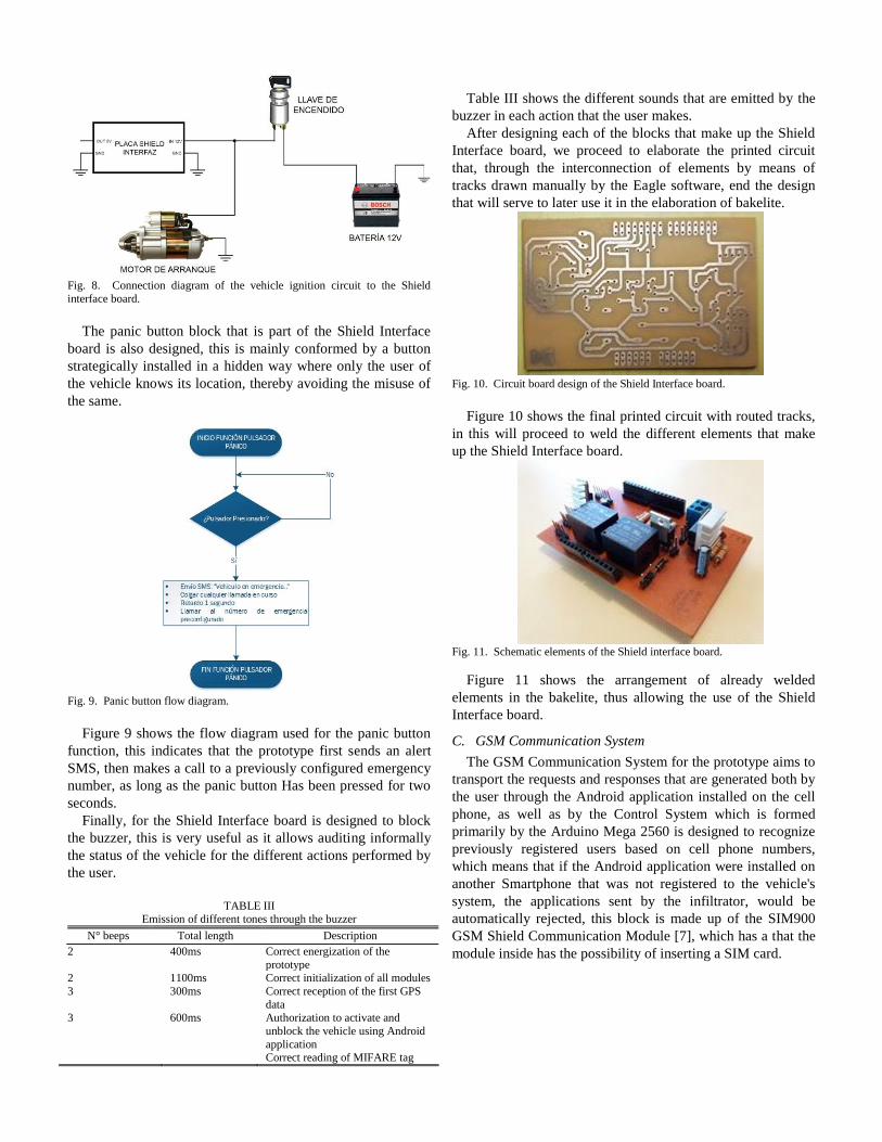
Fig. 8. Connection diagram of the vehicle ignition circuit to the Shield
interface board.
The panic button block that is part of the Shield Interface
board is also designed, this is mainly conformed by a button
strategically installed in a hidden way where only the user of
the vehicle knows its location, thereby avoiding the misuse of
the same.
Fig. 9. Panic button flow diagram.
Figure 9 shows the flow diagram used for the panic button
function, this indicates that the prototype first sends an alert
SMS, then makes a call to a previously configured emergency
number, as long as the panic button Has been pressed for two
seconds.
Finally, for the Shield Interface board is designed to block
the buzzer, this is very useful as it allows auditing informally
the status of the vehicle for the different actions performed by
the user.
TABLE III
Emission of different tones through the buzzer
N° beeps Total length Description
2 400ms Correct energization of the
prototype 2 1100ms Correct initialization of all modules
3 300ms Correct reception of the first GPS
data 3 600ms Authorization to activate and
unblock the vehicle using Android
application Correct reading of MIFARE tag
Table III shows the different sounds that are emitted by the
buzzer in each action that the user makes.
After designing each of the blocks that make up the Shield
Interface board, we proceed to elaborate the printed circuit
that, through the interconnection of elements by means of
tracks drawn manually by the Eagle software, end the design
that will serve to later use it in the elaboration of bakelite.
Fig. 10. Circuit board design of the Shield Interface board.
Figure 10 shows the final printed circuit with routed tracks,
in this will proceed to weld the different elements that make
up the Shield Interface board.
Fig. 11. Schematic elements of the Shield interface board.
Figure 11 shows the arrangement of already welded
elements in the bakelite, thus allowing the use of the Shield
Interface board.
C. GSM Communication System
The GSM Communication System for the prototype aims to
transport the requests and responses that are generated both by
the user through the Android application installed on the cell
phone, as well as by the Control System which is formed
primarily by the Arduino Mega 2560 is designed to recognize
previously registered users based on cell phone numbers,
which means that if the Android application were installed on
another Smartphone that was not registered to the vehicle's
system, the applications sent by the infiltrator, would be
automatically rejected, this block is made up of the SIM900
GSM Shield Communication Module [7], which has a that the
module inside has the possibility of inserting a SIM card.
Fig. 12. GPRS/GSM Shield v2 SIM900 module.
Figure 12 shows the physical form of the SIM900 GSM
module used in the development of the prototype.
TABLE IV
Technical specifications GSM SIM900 module.
Characteristic Detail
Operation Bands 850/900/1800/1900MHz
Supply voltage 5V
Energy consumption Sleep Mode: 1,5mA
Continuo: 500mA
Maximum: 2A
Antenna PCB external type
Power of transit 30dBm (1W)
Supported protocols TCP/UDP
Serial communication Variable, default 9600 baudios
Command set Full control with AT commands
Headphones / Microphone Jack 3.5mm 2 in 1
SIM External Tray
Table IV shows the characteristics of the SIM900 GSM
communication module. It can be highlighted that it has full
compatibility with the Arduino Mega 2560 electronic
development board, as the connection pins are easily adapted
to the prototype design , also counts on an easy configuration
since it is done through AT commands or through bookshops
designed specifically for this module, in addition the power
consumption, reduced size, quad support and the Jack 2 in 1 of
headphones do the best Choice option as GSM communication
module for use in the prototype to be developed.
D. Location System
The Location System is responsible for receiving the signals
sent by the GPS satellites in orbit, this block receives this
information periodically so that it is always available for when
it is necessary to know the location of the vehicle, the
information received is sent to Control System which
processes and converts it into a predefined format, so that it
can be sent to the user when requested, the request for
localization by the user is done through the Android
application installed on the Smartphone of the registered user
to the system, once the request is made, the Control System
through the GSM Communication System conformed by the
GPS module NEO-6M [8], will send the response to the user
in SMS format, showing a link to the GPS location , indicating
also the speed of travel and height at sea level of the vehicle.
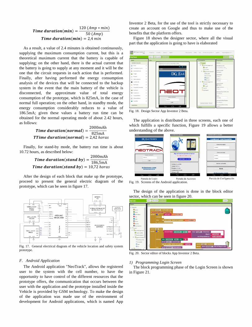
Fig. 13. GPS NEO-6M module.
Figure 13 shows the physical form of the NEO-6M GPS
module used in the development of the prototype.
TABLA V
Technical specifications GPS NEO-6M module.
Characteristic Detail
Comunicación Serial (UART)
Supply voltage 3,3 – 6V
Energy consumption Tracking: 30mA
Acquisition: 45mA
Antenna Active ceramics included
Status indicator LED
Size 22x22mm (antenna)
23x30mm (module)
Frequency of data update 1Hz
Operating Limits Altitude (18000m)
Speed (515 m/s) Sensitivity Capture (-148dBm)
Tracking (-161dBm)
Frequency of reception L1 (1575,42 Mhz)
Operating temperature -40 °C a 85 °C
Table V shows the most relevant features of the GPS
module NEO-6M, where it is possible to emphasize that it is
easy to acquire, it also provides a high performance thanks to
its high sensitivity and operating temperature, allows to obtain
latitude data , Length, speed, altitude, among others,
information essential for the development of the project, on
the other hand, has been designed to work with a low power
consumption, in addition to being small size, the module
perfectly adapts to the hardware of the prototype, due to the
serial communication UART that it provides, finally, the
power voltage that it needs for its operation is flexible and
varies from 3.3V to 6V, given the characteristics presented
above, this module becomes suitable for use in The
elaboration of the prototype.
E. Power System
The Power System is responsible for supplying the
necessary voltage to each of the devices and modules that
make up the entire prototype, it is distributed in several stages,
which fulfill a specific functionality. A special feature is one

that allows the prototype to continue normal operation for the
GPS function and the telephone call service in a time
determined by the capacity of the backup battery, in case the
main battery of the vehicle is disconnected.
Fig. 14. Block Diagram of the Power system.
There are two stages that make up the entire power system,
as described below:
• Power supply
The power supply is a very important stage, because it
receives the voltage provided by the vehicle battery that is
12V, where it reduces it and regulates the voltage necessary
for the operation of the prototype.
• Power backup
The power backup consists of a 7.4V lithium battery that is
connected directly to the Control System and to the Shield
Interface board.
1) Energy consumption analysis
In this section an analysis of energy consumption of the
different devices that make up the entire prototype is
performed. On the one hand, it will analyze the extreme case,
in which all the devices are in full operation; On the other
hand, the case when the main battery of the vehicle is
disconnected.
Power consumption of the board Arduino Mega 2560
For the case where the main battery of the 12V vehicle is
connected, the analysis suggests, for the communication of the
GSM, GPS and NFC modules it is necessary eight pins, where
the sum of current consumption would result in 160mA in
total; on the other hand the communication of the Shield
Interface board requires six communication pins, resulting in a
sum of currents of 120mA; finally the power of the GSM
module is based on the Arduino board, then this is added
500mA, to finally result in a value of 780mA in the event that
all the devices will be in full operation. Now, in case the main
battery of the vehicle is disconnected, the power consumption
is reduced, where for the communication of the GSM, GPS
and NFC modules follow in the same way, but the pins that
are connected to the shield Shield Interface would not come
into operation, in order to finally have a current consumption
of 660mA.
Power consumption of the Shield interface board
The Shield Interface board has several devices connected,
some of which are directly related to the control circuits of the
vehicle, so it is necessary to analyze the two cases of
operation; then for the case where the main battery of the
vehicle is connected, the analysis suggests, for the activation
of relays both to open or close doors, the power consumption
is 70mA for each, giving a sum of 140mA; on the other hand,
the automotive relay that serves to drive the gasoline pump
has an energy consumption of 135mA; finally, the GPS
module and NFC for its power consume an energy of 45mA
and 120mA respectively, adding these two gives 165mA.
Finally giving a sum of current consumption for the Shield
Interface Board of 440mA.
Now, in case the main battery of the vehicle is
disconnected, the relays for both opening and closing doors as
well as for the operation of the petrol pump are inactive, since
they operate at a voltage of 12V, then only the power supply
for the GPS and NFC modules is in operation, finally giving a
sum of current consumption for the Shield Interface board of
165mA.
Total power consumption of the prototype
For the case where the main battery of the vehicle is placed,
the following energy consumption is obtained, using equation
5:
𝑻𝒐𝒕𝒂𝒍 𝑷𝒐𝒘𝒆𝒓 𝑪𝒐𝒏𝒔𝒖𝒎𝒑𝒕𝒊𝒐𝒏(𝒃𝒂𝒕_𝟏𝟐𝒗)= 𝐴𝑟𝑑𝑢𝑖𝑛𝑜 𝑀𝑒𝑔𝑎 2560+ 𝑆ℎ𝑖𝑒𝑙 𝐼𝑛𝑡𝑒𝑟𝑓𝑎𝑐𝑒 𝐵𝑜𝑎𝑟𝑑
(5)
𝑻𝒐𝒕𝒂𝒍 𝑷𝒐𝒘𝒆𝒓 𝑪𝒐𝒏𝒔𝒖𝒎𝒑𝒕𝒊𝒐𝒏(𝒃𝒂𝒕_𝟏𝟐𝒗)= 780𝑚𝐴 + 440𝑚𝐴
𝑻𝒐𝒕𝒂𝒍 𝑷𝒐𝒘𝒆𝒓 𝑪𝒐𝒏𝒔𝒖𝒎𝒑𝒕𝒊𝒐𝒏(𝒃𝒂𝒕_𝟏𝟐𝒗) = 1,220𝐴
On the other hand, in the event that the main battery of the
vehicle was disconnected and the power backup started to
operate, it has:
𝑻𝒐𝒕𝒂𝒍 𝑷𝒐𝒘𝒆𝒓 𝑪𝒐𝒏𝒔𝒖𝒎𝒑𝒕𝒊𝒐𝒏(𝒃𝒂𝒕_𝒍𝒊𝒑𝒐)= 660𝑚𝐴 + 165𝑚𝐴
𝑻𝒐𝒕𝒂𝒍 𝑷𝒐𝒘𝒆𝒓 𝑪𝒐𝒏𝒔𝒖𝒎𝒑𝒕𝒊𝒐𝒏(𝒃𝒂𝒕_𝒍𝒊𝒑𝒐) = 825𝑚𝐴
Total power consumption of the prototype in standby
mode
The power consumption is given in case the prototype is
waiting for some action on the part of the user, then the power
of the GSM, GPS and NFC modules have an energy
consumption of 1.5mA, 45mA and 100mA respectively,
giving a total power consumption of 146.5mA. In Arduino
Mega 2560 board the GPS module communication pins are
constantly functional since it sends periodic data to the board,
then the power consumption would be 40mA, since each pin
consumes 20mA.
𝑻𝒐𝒕𝒂𝒍 𝒆𝒏𝒆𝒓𝒈𝒚 𝒄𝒐𝒏𝒔𝒖𝒎𝒑𝒕𝒊𝒐𝒏 𝒔𝒕𝒂𝒏𝒅 𝒃𝒚= 1,5𝑚𝐴 + 45𝑚𝐴 + 100𝑚𝐴 + 40𝑚𝐴
𝑻𝒐𝒕𝒂𝒍 𝒆𝒏𝒆𝒓𝒈𝒚 𝒄𝒐𝒏𝒔𝒖𝒎𝒑𝒕𝒊𝒐𝒏 𝒔𝒕𝒂𝒏𝒅 𝒃𝒚 = 186,5𝑚𝐴

2) Power Supply
After performing the analysis of energy consumption by the
prototype, then it is necessary to make the choice of the
voltage regulator module, since it is responsible for supplying
the voltage and current needed to operate the majority of
devices involved in the prototype, therefore, it is imperative
that the module supplies the necessary current, thus avoiding
overheating and thus any possible damage.
Fig. 15. LM2596s voltage regulator module.
Figure 15 shows the voltage regulator module based on the
integrated circuit LM2596s [9].
TABLE VI
Technical Specifications LM2596s voltage regulator module.
Characteristic Detail
Output Voltage Range 1,2V a 37V
Max Input Voltage 40V
Output current load 3.0A
Input voltage Up to 40V
Stand-by current consumption Typically 80µA
Types of packaging TO-220, TO-223
Protections Current limit and thermal shutdown
Size 45 (Length) x 20 (Width) x 14
(Height) mm Price $5
Table VI shows the characteristics of the voltage regulating
module LM2596s, where it is highlighted that the output
current load is 3A and satisfies the energy consumption
analysis performed previously, in addition, its small size, the
low consumption in standby, make this module the best option
as a power source in the development of the prototype.
3) Power backup
On the other hand, for the correct choice of the
characteristics of the battery that is going to be used as backup
stage the following points must be taken into account:
Voltage of the battery: The voltage that will have the
battery is of 7.4V, value determined by the input voltage
corresponding to the power Jack of the electronic
development board Arduino Mega 2560 which is between
7 to 12V, all this since this plate conforms the Control
System and also feeds the GSM module directly; on the
other hand the battery also supplies the necessary voltage
to the Shield Interface plate, specifically to the 3.3V
voltage regulator circuit, which supplies the power to the
GPS and NFC module.
Battery capacity: The battery capacity is determined after
the previous analysis of power consumption of the
different devices that will be fed to the backup stage. For
the present project was made the choice of a battery with
a capacity of 2000mAh, all this since this value meets the
requirements of energy consumption analyzed previously
and also has a considerable margin of safety against
possible overloads.
Fig. 16. 7,4V LIPO battery.
The backup battery used is shown in figure 16, in addition
in Table VII it is possible to observe the characteristics of the
same presented by the manufacturer.
TABLE VII
Technical Specifications LIPO battery.
Characteristic Detail
Voltage 7,4V
Battery Capacity 2000mAh
Download speed 25C
4) Backup battery life time
There is a general formula that allows the calculation of the
battery life time, which is shown in equation 6.
𝑻𝒊𝒎𝒆 𝒅𝒖𝒓𝒂𝒕𝒊𝒐𝒏(𝒎𝒊𝒏)
=𝐵𝑎𝑡𝑡𝑒𝑟𝑦 𝐶𝑎𝑝𝑎𝑐𝑖𝑡𝑦(𝐴𝑚𝑝 ∗ 𝑚𝑖𝑛)
𝐷𝑖𝑠𝑐ℎ𝑎𝑟𝑔𝑒 𝑆𝑝𝑒𝑒𝑑(𝐴𝑚𝑝)
(6)
It is known that the capacity of the battery used for the
present project has a value of 2000mAh, then this capacity
must be converted to Amperes per minute, then you have:
𝑩𝒂𝒕𝒕𝒆𝒓𝒚 𝑪𝒂𝒑𝒂𝒄𝒊𝒕𝒚 = 2𝐴 ∗ 60𝑚𝑖𝑛
𝑩𝒂𝒕𝒕𝒆𝒓𝒚 𝑪𝒂𝒑𝒂𝒄𝒊𝒕𝒚 = 120 (𝐴𝑚𝑝 ∗ 𝑚𝑖𝑛)
On the other hand, the discharge rate of the battery in units
of amps is given by equation 7.
𝑫𝒐𝒘𝒏𝒍𝒐𝒂𝒅 𝒔𝒑𝒆𝒆𝒅 (𝑨)
= Download speed∗ Capacidad (𝐴)
(7)
𝑫𝒐𝒘𝒏𝒍𝒐𝒂𝒅 𝒔𝒑𝒆𝒆𝒅 (𝑨) = 25 ∗ 2A
𝑫𝒐𝒘𝒏𝒍𝒐𝒂𝒅 𝒔𝒑𝒆𝒆𝒅 (𝑨) = 50A
Then the time that will last the battery supplying the current
of maximum consumption is obtained by replacing the data
previously calculated in equation 6:
𝑻𝒊𝒎𝒆 𝒅𝒖𝒓𝒂𝒕𝒊𝒐𝒏(𝒎𝒊𝒏) =120 (𝐴𝑚𝑝 ∗ 𝑚𝑖𝑛)
50 (𝐴𝑚𝑝)
𝑻𝒊𝒎𝒆 𝒅𝒖𝒓𝒂𝒕𝒊𝒐𝒏(𝒎𝒊𝒏) = 2,4 𝑚𝑖𝑛
As a result, a value of 2.4 minutes is obtained continuously,
supplying the maximum consumption current, but this is a
theoretical maximum current that the battery is capable of
supplying; on the other hand, there is the actual current that
the battery is going to supply at any moment and it will be the
one that the circuit requests in each action that is performed.
Finally, after having performed the energy consumption
analysis of the devices that will be connected to the backup
system in the event that the main battery of the vehicle is
disconnected, the approximate value of total energy
consumption of the prototype, which is 825mA, in the case of
normal full operation; on the other hand, in standby mode, the
energy consumption considerably reduces to a value of
186.5mA; given these values a battery run time can be
obtained for the normal operating mode of about 2.42 hours,
as follows:
𝑻𝒊𝒎𝒆 𝒅𝒖𝒓𝒂𝒕𝒊𝒐𝒏(𝒏𝒐𝒓𝒎𝒂𝒍) =2000mAh
825mA
𝑻𝑻𝒊𝒎𝒆 𝒅𝒖𝒓𝒂𝒕𝒊𝒐𝒏(𝒏𝒐𝒓𝒎𝒂𝒍) = 2,42 ℎ𝑜𝑟𝑎𝑠
Finally, for stand-by mode, the battery run time is about
10.72 hours, as described below:
𝑻𝒊𝒎𝒆 𝒅𝒖𝒓𝒂𝒕𝒊𝒐𝒏(𝒔𝒕𝒂𝒏𝒅 𝒃𝒚) =2000mAh
186,5mA
𝑻𝒊𝒎𝒆 𝒅𝒖𝒓𝒂𝒕𝒊𝒐𝒏(𝒔𝒕𝒂𝒏𝒅 𝒃𝒚) = 10,72 ℎ𝑜𝑟𝑎𝑠
After the design of each block that make up the prototype,
proceed to present the general electric diagram of the
prototype, which can be seen in figure 17.
Fig. 17. General electrical diagram of the vehicle location and safety system prototype.
F. Android Application
The Android application "NeoTrack", allows the registered
user to the system with the cell number, to have the
opportunity to have control of the different resources that the
prototype offers, the communication that occurs between the
user with the application and the prototype installed inside the
Vehicle is provided by GSM technology. To make the design
of the application was made use of the environment of
development for Android applications, which is named App
Inventor 2 Beta, for the use of the tool is strictly necessary to
create an account on Google and thus to make use of the
benefits that the platform offers.
Figure 18 shows the designer sector, where all the visual
part that the application is going to have is elaborated
Fig. 18. Design Sector App Inventor 2 Beta.
The application is distributed in three screens, each one of
which fulfills a specific function, Figure 19 allows a better
understanding of the above.
Fig. 19. Screens of the Android application.
The design of the application is done in the block editor
sector, which can be seen in figure 20.
Fig. 20. Sector editor of blocks App Inventor 2 Beta.
1) Programming Login Screen
The block programming phase of the Login Screen is shown
in Figure 21.

Fig. 21. Block Programming of the Login Screen.
2) Schedule Action Screen
Block programming of the Action Screen is shown in
Figure 22.
Fig. 22. Block Programming of the Actions Screen.
3) Settings Configuration Screen
The block programming of the Configuration Screen is
shown in Figure 23.
Fig. 23. Block programming of the Configuration Screen.
III. RESULTS AND DISCUSSION
A. Description of the implemented prototype
The prototype is built by several blocks that are conformed
in turn by electronic devices that allow the correct operation of
the same, it has a cell phone number stored on a SIM card, the
system can be installed in any motor vehicle, provides the
opportunity to the owner registered previously, to have a
system which allows to know the GPS location and also to
have control of several of the vehicle's resources, which can be
controlled locally or remotely. The location of the vehicle is
achieved thanks to the GPS receiver module, which allows the
user to request the prototype based on an Android application,
to know the location, altitude at sea level and speed of travel
of the vehicle, thanks to the reception of an SMS text message
sent by the prototype to the requester with such information.
The ignition control of the vehicle is based on user
authentication by reading a MIFARE tag through an NFC
reader, in addition to sending an SMS text message
confirming that action to the user. On the other hand, by
means of an Android application the user can control the
different resources of the vehicle of remote way by means of a
Smartphone and a cellular number previously registered to the
system; plus, the strategically installed panic button that, when
pressed, makes an emergency call to a pre-configured number,
allowing you to hear the conversation taking place inside the
vehicle.
Figure 24 shows the bakelite that makes up the Shield
Interface board, in Figure 25 the prototype is shown ready to
make the corresponding connections in the vehicle, and Figure
26 shows the wiring made from the prototype to the systems to
be controlled in the vehicle.
Fig. 24. Shield Interface Board.
Fig. 25. Interior of the prototype installed inside the vehicle.
Fig. 26. Wiring from the prototype to the vehicle.
B. Implementation and functional tests
For the implementation of the prototype was made use of a
Renault Sandero 2012 car as shown in figure 27, this has a
factory installed central locking system of doors, which the
prototype will control, in addition in the internal part of the
sufficient space, which facilitates implementation work.
Fig. 27. Renault Sandero 2012.
After performing the main power interconnection from the
vehicle battery, it is proceeded to install each of the devices
that will go inside the vehicle, which will be connected to the
prototype, these are, microphone, NFC reader, panic button
and the USB cable, on the other hand, in figure 28 the
interconnection of the cables carrying the different control
signals of the central locking of the vehicle can be observed.
Fig. 28. Connection of the central locking signals.
As a last step, the interconnection of the different cables
that carried the signals that control the operation of the
gasoline pump was made, this is also conformed by a fuse of
5A used to prevent possible damages by overloads. In
addition, the cable carrying the contact signal was connected
as shown in figure 29.
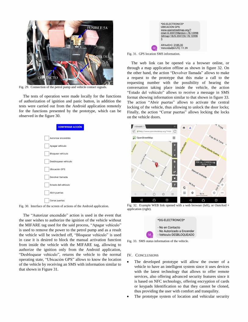
Fig. 29. Connection of the petrol pump and vehicle contact signals.
The tests of operation were made locally for the functions
of authorization of ignition and panic button, in addition the
tests were carried out from the Android application remotely
for the functions presented by the prototype, which can be
observed in the figure 30.
Fig. 30. Interface of the screen of actions of the Android application.
The “Autorizar encendido” action is used in the event that
the user wishes to authorize the ignition of the vehicle without
the MIFARE tag used for the said process, “Apagar vehículo”
is used to remove the power to the petrol pump and as a result
the vehicle will be switched off, “Bloquear vehículo” is used
in case it is desired to block the manual activation function
from inside the vehicle with the MIFARE tag, allowing to
authorize the ignition only from the Android application,
“Desbloquear vehículo”, returns the vehicle to the normal
operating state, “Ubicación GPS” allows to know the location
of the vehicle by receiving an SMS with information similar to
that shown in Figure 31.
Fig. 31. GPS location SMS information.
The web link can be opened via a browser online, or
through a map application offline as shown in figure 32. On
the other hand, the action “Devolver llamada” allows to make
a request to the prototype that this make a call to the
requesting number with the possibility of hearing the
conversation taking place inside the vehicle, the action
“Estado del vehículo” allows to receive a message in SMS
format showing information similar to that shown in figure 33.
The action “Abrir puertas” allows to activate the central
locking of the vehicle, thus allowing to unlock the door locks;
Finally, the action “Cerrar puertas” allows locking the locks
on the vehicle doors.
Fig. 32. Example WEB link opened with a web browser (left), or OsmAnd + application (right).
Fig. 33. SMS status information of the vehicle.
IV. CONCLUSIONS
The developed prototype will allow the owner of a
vehicle to have an intelligent system since it uses devices
with the latest technology that allows to offer remote
services, also offering advanced security features since it
is based on NFC technology, offering encryption of cards
or keypads Identification so that they cannot be cloned,
thus providing the user with comfort and tranquility.
The prototype system of location and vehicular security

was made taking the best design features of the security
systems offered by the Ecuadorian market, all this after
having elaborated a previous analysis, allowing in this
way to have a prototype with state-of-the-art technology.
An analysis of the open-source technologies available in
the Ecuadorian market was made, allowing, on this basis,
to make the correct choice of the Arduino Mega 2560
electronic development board.
The study of the technologies in GPS, GSM and NFC
communications involved in the development of the
prototype was carried out so that an efficient system could
be developed, complying with the communication
protocols used by the different electronic modules.
The Shield Interface board was designed, which is a card
that allows to obtain a more reliable communication
between the Control System and the different systems that
are controlled within the vehicle, thus generating
considerable space savings, returning to circuitry a lot
more compact.
The Android application "NeoTrack" was developed in
the platform "App Inventor", which is based on a
graphical environment and programming is based on
blocks, thus facilitating the design to the programmer
considerably, the application complies with both
parameters Security at the moment of entering it, counting
on an authentication system, as well as having all the
characteristics that the prototype offers, being shown in
list form, facilitating the operation to the user of the
vehicle.
The user manual of the vehicle location and safety
system, gives the owner of the vehicle an ease of use and
understanding of the features it offers, thus generating the
correct use of the prototype; on the other hand, an
installer's manual was developed, allowing the prototype
to be installed effectively and correctly thanks to its easy-
to-understand electrical and block diagrams, guaranteeing
efficient operation of the prototype.
In the design of the power supplies it is essential to
calculate the thermal coefficient 𝜃𝐽𝐴, for the prototype a
value of 𝜽𝑱𝑨 = 151,51 ℃𝑊⁄ was obtained, then the
manufacturer indicates that if the calculated value is
greater than that presented in the datasheet, the use of an
external heatsink is not required.
The developed prototype offers an important feature of
vehicle security, which is, if the user has made a blocking
of the prototype for some situation based on the Android
application, the vehicle remains in that state
unconditionally until the user does the action The vehicle
battery has been disconnected and reconnected.
V. RECOMMENDATIONS
The present project of prototype of system of location and
vehicle safety is a beginning for future improvements of
the same, then the main recommendation is to continue
the investigation, innovating with the possibility to
improve the benefits of this one currently offers, all this is
possible thanks that the project developed is based on the
open-source platform in both hardware and software.
For future designs in which this prototype serves as the
basis of execution, it is recommended to migrate to GPRS
technology in order to make use of a data plan and
execute all the actions offered by the prototype based on
the Internet, all this since the Infrastructure is provided to
carry out this process.
The implementation of the system inside the vehicle must
be in a place of difficult access for anyone, to avoid any
manipulation. However, the panic button must be in a
non-visible location but accessible to the user.
Train users of the system with the aim that they know
each one of the characteristics that it offers, so that they
can make correct use of the prototype.
At the moment of implementing the prototype, make the
connections in a correct and orderly manner, avoiding
also having bare wires as they could lead to short circuits.
For GPS location and emergency call functions,
regardless of the chosen cellular telephone operator, it is
recommended to constantly check and maintain the
prototype with balance and SMS message package, since
these two characteristics are indispensable to provide a
localization system and optimal vehicle safety for the
user.
Set a locking pattern or password for the smartphone, as
this will give a greater guarantee of security to the system,
preventing in this way that anyone tries to manipulate the
Android application and can get to make use of the
functions that it offers.
Register a second cellular number to the vehicle system in
conjunction with the installation of the Android
application, this being the case in case the smartphone
that bears the number of the main user of the vehicle is
lost, then the new user will keep the same [1] Priorities
than the main user and can perform all the actions offered
by the prototype.
For the registration of the emergency number that will be
configured by the developer, it is recommended that the
smartphone assigned to this number is one that has an
always active line, all this being of vital importance since
it will record the audio of Automatically when there is an
emergency situation.
VI. REFERENCES
[1] «CEDATOS,» Abril 2011. [En línea]. Available: http://www.cedatos.com.ec/detalles_noticia.php?Id=86. [Último acceso:
20 Diciembre 2016].
[2] «ARDUINO,» [En línea]. Available: https://www.arduino.cc/en/Main/ArduinoBoardMega2560. [Último
acceso: 20 Diciembre 2016].
[3] ELECHOUSE. [En línea]. Available: https://dangerousthings.com/wp-content/uploads/PN532_Manual_V3-1.pdf. [Último acceso: 15 Diciembre
2016].
[4] T. INSTRUMENTS, Octubre 2016. [En línea]. Available: http://www.ti.com.cn/cn/lit/ds/symlink/lm117.pdf. [Último acceso: 2016

Diciembre 11].
[5] FAIRCHILD, Noviembre 2014. [En línea]. Available:
https://www.fairchildsemi.com/datasheets/TI/TIP31C.pdf. [Último acceso: 22 Noviembre 2016].
[6] SPARKFUN, Mayo 2003. [En línea]. Available:
https://www.sparkfun.com/datasheets/Components/LM7805.pdf. [Último acceso: 20 Diciembre 2016].
[7] GEEETECH, 15 Diciembre 2015. [En línea]. Available:
http://www.geeetech.com/wiki/index.php/GPRS_Shield_V2.0. [Último acceso: 2016 Diciembre 20].
[8] WAVESHARE, 3 Noviembre 2016. [En línea]. Available:
http://www.waveshare.com/wiki/UART_GPS_NEO-6M. [Último acceso: 20 Diciembre 2016].
[9] T. INSTRUMENTS, Mayo 2016. [En línea]. Available:
http://www.ti.com/lit/ds/symlink/lm2596.pdf. [Último acceso: 15 Diciembre 2016].
Henry David Guerra, Author. He was
born on May 26, 1988 in the city of
Otavalo, province of Imbabura - Ecuador.
He studied at the Technological Institute
"OTAVALO" where he obtained a
bachelor's degree in Electronics, his
studies at the Universidad Técnica del
Norte, obtaining the title of Electronics
Engineer and Communication Networks
in the city of Ibarra.
Omar Oña, Director. Professional in
Electronic Engineering and
Telecommunications. He is currently
Professor of the Faculty of Engineering in
Applied Sciences (FICA) at the
Universidad Técnica de Norte in the
Engineering Career in Electronics and
Communication Networks (CIERCOM),
in areas such as electronics, digital
systems and other related fields. He has experience in the field
of Technical Advice, preventive and corrective maintenance
of computer equipment, installation and maintenance of
networks. Through his service he has worked constantly and
unconditionally in the development of projects of electronics
and telecommunications.