design and implementation of a light duty gantry crane · the crane chassis structure design, motor...
TRANSCRIPT
Design and Implementation of a
Light Duty Gantry Crane
Mohamed H. Mabrouk Head of Mech. Equipment Dept.
M.T.C.
Cairo, Egypt.
Sherif M. M. Abdelkhalek Production Eng. Dept.
M.T.C.
Cairo,Egypt
Abstract— Gantry cranes have recently played a vital role in
handling loads such that they become indispensable for many
industrial facilities. This paper presents the design and
implementation of a light duty gantry crane that can be used
in a workshop. Preliminary design of the gantry crane chassis
structure as well as the used control strategy has been
discussed. The design of the gantry crane chassis has been
verified using a computer model which shows satisfactory
safety factors for the expected loads. A scaled prototype has
been built and used to verify the proposed control circuit of
the crane. The crane chassis structure design, motor power
calculations, the control circuit, and the selection of control
devices and instruments are discussed. The crane then has
been implemented according to standards that govern
building of gantry cranes considering safety precautions and
providing all inspection and maintenance documents that
assure safe operation as well as long service life of the crane.
Keywords— Mechanical systems; materials handling
equipment; control of mechanical equipment, crane prototype
I. INTRODUCTION
In our modern mechanized world, cranes are considered
as the best way of transferring loads from one place to
another and therefore they play a key role in achieving high
productivity and economic growth in many fields such as
construction, mining, maritime operations, and maintenance
of production and service facilities. They can be found in a
wide variety of forms, each designed to suit a specific use,
such as tower crane, overhead crane, mobile boom crane,
gantry crane and others.
Gantry crane provides an economical way to lift heavy
objects anywhere in a facility; hence it is one of the most
commonly used equipment in warehouses and workshops.
Different types of gantry cranes are used in workshops for
various purposes. Conventional gantry cranes can be
classified into fixed height and adjustable height according
to the maximum load height, single girder or double girder
according to the type of girder construction, and wheel
mounted or rail mounted according to the way it moves.
Each type has its own advantages and disadvantages with
respect to the working environment, safety precautions, ease
of use, maintenance, and load capacity [1].
Gantry cranes are generally used to move objects using
the trolley mechanism which constitutes two main parts; the
hoisting mechanism (load raising and lowering mechanism)
and the carriage that moves horizontally along a horizontal
beam called girder, as shown in Fig. 1. Two pillars are used
to support the girder while the trolley mechanism carries the
load from one point to another overhead. The braces are
lateral supports added to the crane chassis structure to
provide support as well as to keep balance of the crane
during operation. Gantry cranes are self movable equipment
such that they either have powered rails at the bottom or
wheels that can help the crane to move within the work
area, as can be seen in Fig.1. The work area of gantry crane
is defined as the area around the crane that is established by
the crane crew using barriers (cones and signage) which
mark the work area boundaries to indicate a limit for
adjacent crane operators. The development of the gantry crane has witnessed
many surges during the last thirty years. Some researches handle the crane mathematical model in different ways [2-4], others focus on the safety precautions and the operation procedures problems [5], while most of researchers concentrate on the development of the crane controller [2-4,6-8]. A single-girder wheel mounted gantry crane is the gantry crane type that is usually used to lift heavy objects in small manufacturing units and warehouses as it provides a more cost-effective lifting solution than expensive permanent structure crane. In this paper, we introduce the design and implementation of a light duty fixed-height single-girder wheel-mounted gantry crane that is attempted to be used in a workshop. The paper is arranged as follows; section II is devoted to present the preliminary design of the crane chassis focusing on the problem definition which leads to the design requirements, assumptions and constraints followed by the computer model to verify the crane chassis structure design presented in section III. Section IV is devoted to present the mathematical model of the crane and the control strategy. Section V is devoted to explain building a prototype and verifying the control circuit of the crane followed by the implementation of the real crane presented in section VI.
International Journal of Engineering Research & Technology (IJERT)
IJERT
IJERT
ISSN: 2278-0181
www.ijert.orgIJERTV3IS120431
(This work is licensed under a Creative Commons Attribution 4.0 International License.)
Vol. 3 Issue 12, December-2014
381

Fig.1. Conventional fixed-height single-girder gantry crane
II. PRELIMINARY DESIGN OF THE CRANE CHASSIS
Considering the problem of moving heavy weights inside a
workshop, the single-girder fixed-height wheel-mounted
gantry crane provides the most flexible lifting solution
offered by different styles of cranes especially for limited
working areas because it can move to cover most of the
work shop area in addition to its low cost and feasible use. It
also avoids many problems that may appear when using
other equipment such as noise when using a forklift,
complex fixation into ground and limited working volume
problems when using the I-beam gantry crane, and complex
structure and the workshop construction limitations
problems when using an overhead crane. The technical
specifications of the gantry crane whose design is presented
in this paper are as follows: loading capacity is 10 tons,
girder height is 3.5 m, pillars' span equals 2.5 m. The main
factors that should be taken into consideration during the
design are the ease of installation to make sure that all
components can be assembled with available tools, the ease
of operation to reduce injuries and increase productivity,
and finally the versatility and safety to assure feasible
operation and economical way to lift loads anywhere in a
facility. Some other factors should be considered such as
keeping minimum cost as possible, easy to move
everywhere, friendly using by the low experienced
operators to provide high performance, reliability, and easy
steering. Considering the requirements of the designed crane
main construction, the main groups of the crane are the crane chassis, the crane mobility system, the power unit, the crane electrical system, load display, alarming system, the crane control unit, and the trolley mechanism that includes the wheeled carriage and the hoisting mechanism. The crane chassis structure constitutes the girder, the pillars, the braces, and the wheel mounted joints (or the base), as shown in Fig.2. For added strength and balance, the girder and pillars of the gantry crane are supported using two types of braces; lateral braces and side braces. The gantry crane is equipped with four wheel mounting assemblies two of which are used to drive the crane while the other two are used for crane steering constituting the mobility system of the crane. The mobility system enables the user to move the crane within the work area inside the workshop with the aid of a proper crane braking system. The assemblies of the wheels can be fixed in the bottom of the crane chassis through four wheel-mounted joints at the base of the crane chassis. The power unit is generally a diesel engine driven
generator that provides electric power necessary to feed the electric motors used to activate the mobility system and the trolley mechanism. Finally, the crane is operated through the control unit that can be used manually.
While designing the crane groups, it is required to design and then optimally select components such as the girder, the pillars, the braces, the wheeled carriage, the crane hook lifting and lowering mechanism, the wire ropes, tie rods, and wheel mounted assembly. Throughout the force analysis, the load has been applied at various positions of the girder especially at the center to generate uniformly distributed moment and stresses over the crane chassis structure which is designed as I- shaped cross sectional steel beams cut and welded to provide the proposed chassis structure.
Fig.2. Proposed design of the gantry crane chassis
After proper calculations, the results for static as well as
dynamic analysis are obtained. In static analysis, crane’s
self weight, payload, hook weight and trolley weight are
considered whereas velocities, acceleration and braking are
considered in dynamic analysis.
Calculating for the preliminary design for the crane chassis
structure, empirical formulae from [9] are considered such
that they are chosen to be compatible with standards
requirements for gantry cranes manufactures [10-12].
General information about the crane are that the crane
maximum load capacity is 10 tons, hoisting speed is 1
m/min. and the speed gear reduction transmission ratio
ranges from 3 to 5 over the system of pulleys in the load
lifting and lowering mechanism. The design and part
selection is explained in the following subsections.
A. Crane Chassis
The crane chassis consists of the girder, base, pillars, and
braces. For the design of the gantry crane chassis, some
International Journal of Engineering Research & Technology (IJERT)
IJERT
IJERT
ISSN: 2278-0181
www.ijert.orgIJERTV3IS120431
(This work is licensed under a Creative Commons Attribution 4.0 International License.)
Vol. 3 Issue 12, December-2014
382

factors should be taken into consideration. It is important to
note that the moment is generally uniformly distributed
across the girder when the load is at the crane central axis
and maximum on one of the legs when the load is at the
other leg of the crane. Therefore, good support at both legs
is necessary to keep the system in balance. Lateral braces at
the girder in addition to cross side braces at the top half and
bottom half of the pillars offer a solution for such problem.
On the other hand, it is intended to have the center of
gravity of the system located as near as can be to the bottom
of the crane chassis structure, and so the center of mass
obligates the system to remain in balance, regardless of the
magnitude of the load, which is expected to be less than the
total mass of the crane. This can be achieved through
designing the chassis structure base to cover an area that
keep appropriate position of the center of gravity along the
chassis central axis. Other factors to be considered during the design of the
crane can be summarized in the resistance due to load swing, the influence of the wind, and the acceleration of the moving masses. However, these factors can be ignored considering lack of wind effect due to indoor operation, and choosing low speeds for load hoisting and movement. Another important factor is to ensure the operating safety as a simple mistake can lead to tragic accidents most of which are caused by unsecured load and load capacity exceeded [13]. The chassis different parts are standard steel parts that are connected using welding and bolted joints to form the final chassis structure. All structure parts, welding and bolted joints are checked for shear stresses, crushing stresses and bending moment stresses using the recommended factors of safety [9].
B. Trolley Mechanism
The trolley mechanism consists of wheeled carriage and the hoisting mechanism equipped with a ratchet wheel brake system to hold the load at different elevated positions. The carriage drive mechanism consists of a reduced electric motor, which through a fixed coupling, drives an under-hung wheeled carriage that moves on the rails fixed to the girder. The load raising and lowering mechanism consists of a drum, system of pulleys, speed gear reduction, and an electric motor. It also includes a hook meant to be attached to the load and steel wire ropes. All parts and mechanisms are chosen using formulae from [9] according to the load such that they are chosen to be compatible with standards recommended for gantry cranes manufactures [10-12].
C. Crane Mobility System
The basic task of the mobility system is to enable the user to move the crane within the work area. The mobility system of the crane includes two main systems; the crane driving system, which is used to move the crane forward or backward, and the crane steering system, which is used to direct the crane motion. Each system depends on two DC- reduced electric motors to accomplish its task. The mobility system is controlled using the control unit through the electric wire system and the control devices. A braking system is used to stop the crane or to reduce its speed.
D. Power Unit and Motor Selection
Considering power calculations, a 7 KW diesel engine derived generator is used as a power unit for the crane to feed the four 0.75 KW reduced electric motors that are used in the mobility system, the 3 KW reduced electric motor that is used in the hoisting mechanism, and the 1 KW reduced electric motor that is used to drive the wheeled carriage. All speeds are limited to 0.015 m/s to avoid load swing as well as inertia effects.
III. COMPUTER MODELING AND DESIGN VERIFICATION
In this stage of the design procedure, it is important to make sure that the crane chassis design is applicable. A complete stress analysis of the crane chassis structure is performed using a computer model that has been developed for the crane chassis with all forces, moments and constraints distributed on it to calculate von mises stresses, first principal stresses and third principal stresses that influence the crane. The results show acceptable values of safety factors and strains, as shown in Fig. 3 to Fig.11.
Fig. 3. Von Mises stress
Fig. 4. First principal stress
International Journal of Engineering Research & Technology (IJERT)
IJERT
IJERT
ISSN: 2278-0181
www.ijert.orgIJERTV3IS120431
(This work is licensed under a Creative Commons Attribution 4.0 International License.)
Vol. 3 Issue 12, December-2014
383

Fig.5. Third principal stress
Fig. 6. Displacement
Fig. 7. Safety factor
Fig. 8. Equivalent strain
Fig. 9. First principal strain
Fig.10. Third principal strain
International Journal of Engineering Research & Technology (IJERT)
IJERT
IJERT
ISSN: 2278-0181
www.ijert.orgIJERTV3IS120431
(This work is licensed under a Creative Commons Attribution 4.0 International License.)
Vol. 3 Issue 12, December-2014
384
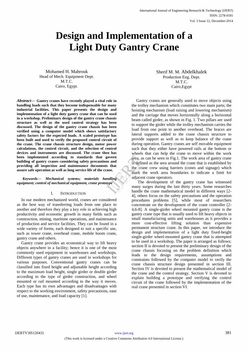
IV. MATHEMATICAL MODEL FOR THE CRANE
Recent research in the domain of gantry crane
development focuses primarily on developing efficient
techniques for load position control. However, before
adopting a control strategy, system dynamics modeling
needs be identified. Gantry cranes which are commonly
used in workshops and factories usually incorporates a
carriage, which translates in a horizontal plane with the load
attached to it by a cable, whose length can be varied using
the hoisting mechanism. In this common type of gantry
cranes, the load with the cable can be treated as a one-
dimensional pendulum, shown in Fig.11, with one-degree-
of-freedom sway. If the swing exceeds a proper limit, it
must be damped or the operation must be stopped until the
swing dies out. Here we deduce a linearized model for the crane with
nonlinearities, such as coulomb friction, assumed to be not included as the friction results in high steady-state error of position control [2]. Also for obtaining a solution of the dynamic equation that represent the behavior of the system, both acceleration and hence inertia forces are considered zero. The load hanged at the end of a wire, which is assumed always tensioned under the load weight as can be observed from Fig.11. At a particular time t1, the carriage moves to position x
1, the force that has been applied on the
carriage is u, the mass of the carriage is mC, the mass of
load is mL, the length of the wire is l, and the angle between
the wire and vertical axis is θ.
Mathematical model for the crane is derived such that the dynamics of the system is analyzed by splitting the system into two parts, which are carriage and load through developing their free body diagrams. Therefore, the dynamic equations that represent the system are as follows [2]:
(1)
(2)
Deriving the equations in the state space format, we obtain:
(3)
Fig.11. Gantry crane model
solving the above equation yields:
(4)
In attempts to reach load position control with acceptable
anti-swing crane operation, gantry crane controller can be
commonly either a classical proportional derivative (PD)
controller based on delayed-position feedback [7-8] or
Fuzzy Logic Controller (FLC) [14-16]. For the light duty
cranes, a skilful operator is usually responsible for operating
the crane such that the load is moved from a start position to
end position without swing. Considering that the crane is
manually operated and that the electric motors used in the
trolley mechanism and the mobility system are selected
specifically with low speeds, sway angle is assumed to be
small and the nonlinear equation (4) becomes less complex
and good to work with. Based on the linear model of the
gantry crane, the objective of the crane controller design
here is to move the load from point to point and to minimize
the load swing that can be considered here as neglected
effect. Matlab Simulink is used here to model the system by
developing the respective block functions according to crane dynamic setting requirements and therefore an open-loop Simulink setup is used, as shown in Fig.12. The resultant load oscillation for a 5N amplitude pulse input during 1 sec time duration is shown in Fig. 13. The main advantage of using such input is to present the problem in real form especially in case of considering ideal conditions and therefore neglecting some factors as the effect of load swing and damping friction [17]. From load oscillation results, shown in Fig. 13, it can be concluded that the load swing is within an acceptable range [2] without any further requirements for anti-swing special controller.
International Journal of Engineering Research & Technology (IJERT)
IJERT
IJERT
ISSN: 2278-0181
www.ijert.orgIJERTV3IS120431
(This work is licensed under a Creative Commons Attribution 4.0 International License.)
Vol. 3 Issue 12, December-2014
385

Fig.12. Simulink Setup for gantry Crane
Fig. 13. Load oscillation for step input
V. PROTOTYPE IMPLEMENTATION AND CONTROL
CIRCUIT VERIFICATION
In order to verify the proposed load position control circuit,
a prototype has been built for the gantry crane. The
blueprints of the gantry crane design, discussed in the
previous section, provided us with detailed dimensions that
have been used to build a scaled prototype in the department
of mechanical equipment, MTC, as shown in Fig. (14).The
main construction of the prototype are the crane chassis that
consists of the girder, base, legs, braces, and trolley
mechanism that consists of the carriage and the load
hoisting mechanism. The main technical specifications of
the prototype can be summarized as the girder height is 110
cm, the crane span width is 90 cm while the crane can move
in a plane using the two driving wheels along with two
steering wheels mobility system. The chassis of the
prototype is a steel frame with two kinds of braces that
assure the achieving of the proper balance and support of
the crane during operation. Attached to the girder, a
wheeled carriage that runs on rails fixed along the girder to
move the load. The carriage is a four wheels metal cart that
moves on rails fixed along the girder through gear
arrangement that is powered by an onboard electric motor,
as shown in Fig.(15) . The carriage hosts the winch reduced
electric motor that lifts the load through a system of pulleys.
In the prototype, the load position is controlled
using the control circuit that has been proposed in the
previous section to make sure that the load position control
strategy works properly. Arduino Uno is used here to make
control for crane prototype trolley mechanism. The
recognition and control algorithms are written in micro-C
programming language. The control algorithms are used to
control the two motors which drive the carriage and load
hoisting mechanism. The control circuit components
include breed board, wires with pushbuttons, 2 DC- geared
motors' drivers, resistors, encoder sensors, limit switch
sensors and 12v battery used as a power source. Each motor
is attached to two digital pins from the Arduino, one of
digital pins is used to control the speed through pulse width
modulation (PWM) variations and the other to control the
motor shaft rotation direction. However, in this design the
motor speeds are selected such that their speeds are kept
low and constant to avoid load swing and inertia forces.
Two twelve step rotary encoders are used for controlling
the horizontal distance travelled by the carriage and the
vertical distance travelled by the wire during lifting or
lowering the load, same installation procedures from [18] is
used.
Fig. 14. Gantry crane prototype
Fig. 15. Prototype trolley mechanism (derived by two DC motors)
VI. IMPLEMETATION OF FULL SCALE CRANE
The proper design, safe operation, and optimum use of
overhead and gantry cranes are governed by the American
Society of Mechanical Engineers (ASME) standards and
the Occupational Safety and Health Administration
(OSHA) regulations. All design reports, blueprints,
drawings and calculation reports resulted from work
International Journal of Engineering Research & Technology (IJERT)
IJERT
IJERT
ISSN: 2278-0181
www.ijert.orgIJERTV3IS120431
(This work is licensed under a Creative Commons Attribution 4.0 International License.)
Vol. 3 Issue 12, December-2014
386
presented in this paper have been passed to a contractor
that is compliant to gantry crane manufacturers’
requirements. The contractor builds the crane using a dated
working plan according to implements requirements
criteria from [9-12]. The crane consists of five main
components which are the crane chassis, the hoisting
mechanism, the crane mobility system, the control unit, and
the power unit.
Fig. 16. Crane trolley mechanism
Fig. 17. Crane mobility system
Fig. 18. Crane control unit
The chassis is considered as the skeleton of the crane since
it holds all the crane systems together. It consists of the
girder, 10 knees, 2 pillars, and four wheel mounted joints
base. The girder is made of a steel I-beam connected to the
two crane pillars that are made of hollow square cross
section beam, which are supported together by 10 knees
made also of hollow square cross section beam with the
base structure made of steel I-beam cross-sectional parts
welded and bolted to form the required designed base shape.
Figure 16 shows the crane trolley mechanism that
is assembled with the chassis. The mechanism is powered
using two electric motors assigned for hoisting the load and
driving the carriage. The lifting motor can left up to 10 tons
while the carriage driving motor moves the load with a low
constant speed across the girder span. The crane mobility
system, shown in Fig. 17, consists of steering and driving
mechanisms. Each mechanism is driven by two 0.75 Kw
electric motors with built-in reduction gear boxes. The
control unit, shown in Fig. 18, includes the crane electric
wiring collecting nodes, control switches, safety precaution
switches and emergency buttons, control pendant is
supported as well. The power unit of the crane is a generator
driven by a diesel engine that can deliver up to 7 Kw to the
electric motors of the crane trolley mechanism and mobility
system. Considering the fact that cranes can be a very dangerous
piece of equipment, it is crucial to follow basic craning hazard prevention measures that ensure the safety of all personnel who may be in the immediate areas where cranes are being operated. The load test for the crane has been proceeded with a calibrated load measuring device and all dimensions and calculations have been double checked and determined to be accurate within acceptable tolerance. Then the load test report and load chart have been developed. The maintenance file of the crane, which is a compilation of all documents related to the crane inspection and repair, has been developed. It includes dated periodic inspection records and other documentation to provide an evidence of a safe and reliable maintenance program. It includes documents such as crane daily inspection checklist, maintenance post-operative checklist and records related to operation, maintenance, inspection, testing, evaluation, and repair of the equipment. Maintenance file information should provide a source for comparing present conditions with past conditions to determine whether existing conditions show a trending pattern of wear, deterioration, or other comparable factors that may compromise safe or continued use of the equipment.
CONCLUSIONS
This paper presents the design and implementation of a light
duty gantry crane that can be used to execute indoor
materials handling operations within small workshops. The
crane design, which includes the crane chassis structure
stress analysis as well as the construction of the crane
trolley mechanism and mobility system, has been discussed.
We have also discussed the design of the crane control
circuit that includes steps such as modeling of the dynamic
crane behavior, the selection of an appropriate control
strategy, and validation of the control circuit using a
prototype of the gantry crane. All design reports, blueprints,
International Journal of Engineering Research & Technology (IJERT)
IJERT
IJERT
ISSN: 2278-0181
www.ijert.orgIJERTV3IS120431
(This work is licensed under a Creative Commons Attribution 4.0 International License.)
Vol. 3 Issue 12, December-2014
387

drawings and calculation reports resulted from work
presented in this paper have been used by a contractor to
build the crane according to standards that govern building
of gantry cranes to assure long service life and safe
operation of the crane.
ACKNOWLEDGMENT
Authors would like to thank Prof. Motaz Aboelnor and Ass. Prof. Mahmoud Ashry for fruitful discussions.
REFERENCES
[1] Lawrence K. Shapiro, Jay P. Shapiro, "Cranes and Derricks", McGraw
Hill Inc., 4th ed., 2010. [2] Hanafy Omar, "Control of Gantry and Tower Cranes", PhD thesis,
Faculty of the Virginia Polytechnic Institute and State University, 2003.
[3] W. O. Connor and H. Habibi, “Gantry crane control of a double-
pendulum, distributed-mass load, using mechanical wave concept,” Mechanical Sciences, vol. 4, pp. 251–261, 2013.
[4] S. Woods and W. Szyszkowski, "Optimal Manoeuvres of
Underactuated Linear Mechanical Systems: The Case of Controlling Gantry Crane Operations", Journal of Applied Mathematics, Article
ID 283565, Volume 2014, 16 pages,
http://dx.doi.org/10.1155/283565/2014 [5] Franklin V.A., "Overhead and Gantry Crane Procedures", Safety and
Health Manual, 2011.
[6] Chung, Y. K., “A neuro-based expert system for facility layout construction.” Journal of Intelligent Manufacturing, 10(5): 359-385.
GG Crane Group 2010.
[7] Henry, R. J., “Cargo pendulation reduction on ship–mounted cranes,” M.S. Thesis, Virginia Tech., Blacksburg, VA, 1999.
[8] Masoud, Z. N., Nayfeh, A. H., Henry, R. J., and Mook D. T., “Sway
reduction on container cranes using delayed feedback controller,” in Proceedings of the 43rd AIAA/ASME/ASCE/AHS/ASC Structures,
Structural Dynamics, and Materials Conference, Denver, CO, AIAA-
2002-1279, 2002. [9] N. Rudenko, "Materials handling equipment", MIR Publisher, Moscow
1969.
[10] ASME B30.17-2006 Overhead and Gantry Cranes (Top Running Bridge, Single Girder, Underhung Hoist)
[11] OSHA 29 CFR 1910.179 - Overhead and Gantry Cranes.
[12] DOE/RL-92-36, Hanford Site Hoisting and Rigging Manual, 2013. [13] “Crane Safety. Issue No. 8: Occupational Safety
Observer.”Internet:http://tis.eh.doe.gov/docs/oso/oso93_08.html
[Dec27 2011] [14] Nalley, M. J. and Trabia, M. B., “Design of a fuzzy logic controller
for swingdamped transport of an overhead crane payload,”
Dynamic System and Control 1, 389–398, 1994. [15] Yang, H., Kinouch, Y., and Sugio, N., 1996, “Anti-swing fuzzy
control of overhead cranes referring a velocity pattern,”Control and
Cybernetics 25(2), 209-281. [16] Al-Moussa, A., Nayfeh, A., and Kachroo, P., “Control of rotary
cranes using fuzzy logic,” in ASME 2001 Design Engineering
Technical Conference and Computers and Information in Engineering Conference, Pittsburgh, PA, September 9-12,
DETC2001/VIB-21598, 2001.
[17] C.R.Houck, J.Joines, andM.Kay. A genetic algorithm for function optimization: A Matlab implementation. ACM Transactions on
Mathematical Software, 1996.
[18] Mohamed H. Mabrouk, "Design and Implementation of an Experimental Test-Rig for Tower Cranes", International Journal of
Engineering Research & Technology (IJERT), ISSN: 2278-0181,
Vol. 3 Issue 10, pp 40-45, 2014.
International Journal of Engineering Research & Technology (IJERT)
IJERT
IJERT
ISSN: 2278-0181
www.ijert.orgIJERTV3IS120431
(This work is licensed under a Creative Commons Attribution 4.0 International License.)
Vol. 3 Issue 12, December-2014
388
