design and implementation of a levitation …
TRANSCRIPT
DESIGN AND IMPLEMENTATION OF A LEVITATION-CONTROLLER
FOR A MAGNETIC LEVITATION CONVEYOR VEHICLE
Jan Van Goethem
Department of Electrical Machines (IEM), Aachen Institute of Technology , Aachen, NRW, 52056, Germany [email protected]
Gerhard Henneberger
Department of Electrical Machines (IEM), Aachen Institute of Technology , Aachen, NRW, 52056, Germany [email protected]
ABSTRACT
In this paper a magnetic levitation control unit based on a state control structure is designed for a one degree of freedom maglev application. Four of these control units will be used to levitate a new conveyor vehicle. The state control algorithm is designed based on a linearised system of state equations of fifth order. The state vector feedback is calculated through eigenvalue assignment. After successful simulation of the linear controller with an accurate nonlinear model of the system the implementation of the controller on a DS1103 PPC Controller Board is presented. Extensive measurement results demonstrate the dynamic and stable performance of the levitation-controller.
INTRODUCTION
The magnetic levitation technique combined with linear drives makes contactless and frictionless operation of a transport system possible. At the IEM a magnetic levitation conveyor vehicle is being designed. It is part of a new conveyor system which can replace conventional conveyor systems at airports. The frictionless operation guarantees lower maintenance costs and longer product life of the hardware.
Basic components of the vehicle are the light weight framework and four levitation/propulsion heads. A levitation/propulsion head consists of a linear homopolar motor [1],[2], a hybrid-excited support magnet and a contactless energy transmission module. Because the energy needed for the whole vehicle is provided by contactless energy transmission, low energy consumption is important. A hybrid-excited support magnet with a current which is set to zero by a controller is selected as magnetic bearing. The track is
completely passive which makes it cheap and easy to manufacture.
The support magnets of the vehicle are independently controlled by 4 state controllers. A controller is designed based on a one degree of freedom model. After discussion of the control unit design the implementation of the controller on a state-of-the-art DS1103 PPC Controller Board is discussed. The real-time code is generated by Real-Time Interface (dSPACE) together with Real-Time Workshop (The Mathworks). Measurement results of a one degree of freedom test bench demonstrate the dynamic and stable performance of the levitation-controller.
THE TEST BENCH
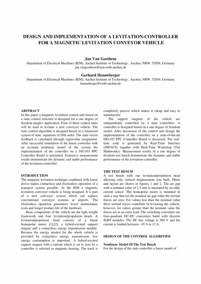
A test bench with one levitation/propulsion head allowing only vertical displacement was built. Photo and layout are shown in figures 1 and 2. The air gap with a nominal value of 2.5 mm is measured by an eddy current sensor. The homopolar motor is mounted in such a way that for the nominal air gap value the normal forces are zero. For values less than the nominal value these normal forces contribute in levitating the vehicle, however, for values greater than the nominal value the forces act as an extra load. The switching converters are four-quadrant DC-DC converters build with discrete IGBT-modules. The DC bus voltage is 300 V and the current is limited between –10 A to 12 A. DESIGN OF THE CONTROL ALGORITHM
Nonlinear Model Of The Test Bench
For the design of the state controller a linear model of
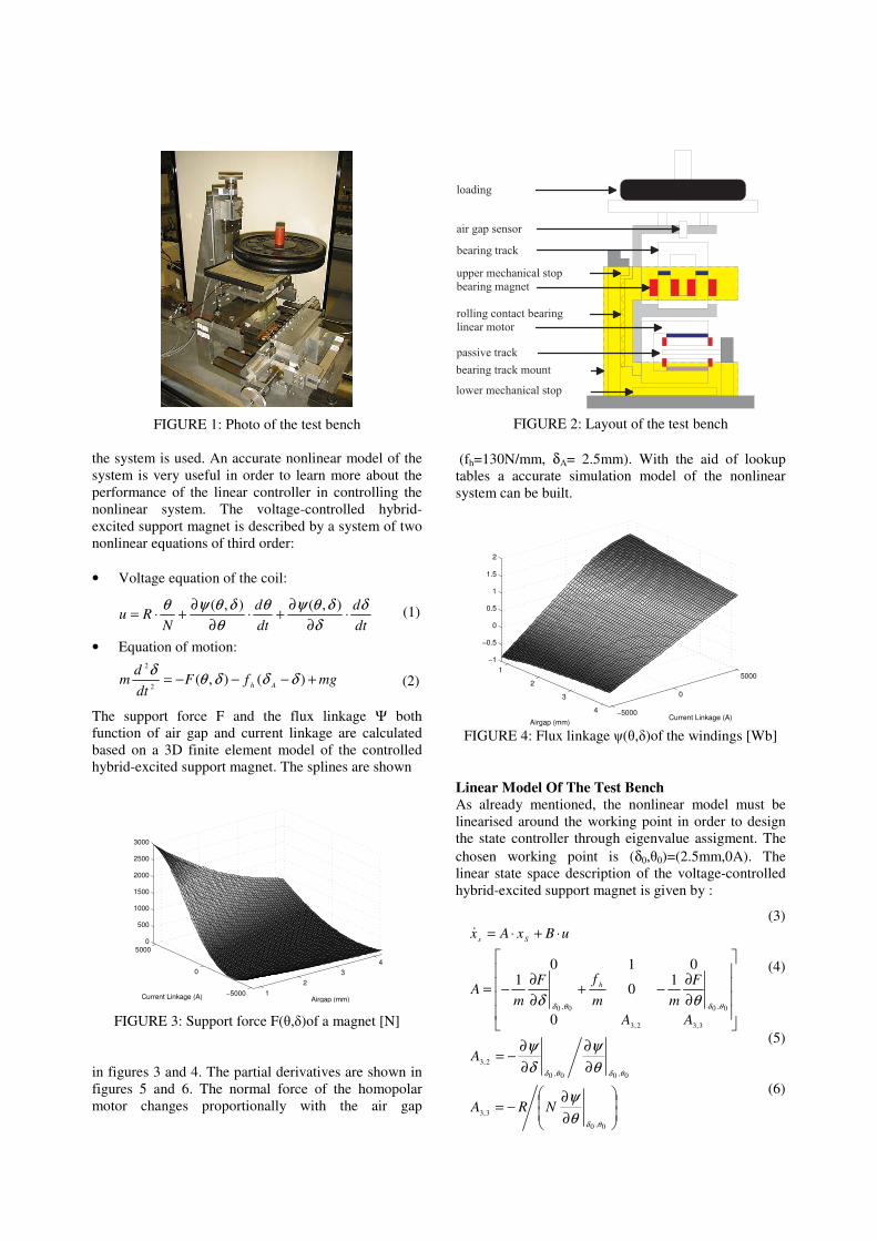
FIGURE 1: Photo of the test bench the system is used. An accurate nonlinear model of the system is very useful in order to learn more about the performance of the linear controller in controlling the nonlinear system. The voltage-controlled hybrid-excited support magnet is described by a system of two nonlinear equations of third order: • Voltage equation of the coil:
(1)
• Equation of motion: (2)
The support force F and the flux linkage Ψ both function of air gap and current linkage are calculated based on a 3D finite element model of the controlled hybrid-excited support magnet. The splines are shown
1
2
3
4
−5000
0
5000
0
500
1000
1500
2000
2500
3000
Airgap (mm)Current Linkage (A)
FIGURE 3: Support force F(θ,δ)of a magnet [N] in figures 3 and 4. The partial derivatives are shown in figures 5 and 6. The normal force of the homopolar motor changes proportionally with the air gap
u p p e r m e c h a n i c a l s t o pb e a r i n g m a g n e tr o l l i n g c o n t a c t b e a r i n gl i n e a r m o t o r
l o w e r m e c h a n i c a l s t o p
p a s s i v e t r a c k
l o a d i n g
a i r g a p s e n s o rb e a r i n g t r a c k
b e a r i n g t r a c k m o u n t
FIGURE 2: Layout of the test bench (fh=130N/mm, δA= 2.5mm). With the aid of lookup tables a accurate simulation model of the nonlinear system can be built.
1
2
3
4 −5000
0
5000
−1
−0.5
0
0.5
1
1.5
2
Current Linkage (A)Airgap (mm)
FIGURE 4: Flux linkage ψ(θ,δ)of the windings [Wb] Linear Model Of The Test Bench
As already mentioned, the nonlinear model must be linearised around the working point in order to design the state controller through eigenvalue assigment. The chosen working point is (δ0,θ0)=(2.5mm,0A). The linear state space description of the voltage-controlled hybrid-excited support magnet is given by :
(3) (4) (5) (6)
dt
d
dt
d
NRu
δ
δ
δθψθ
θ
δθψθ⋅
∂
∂+⋅
∂
∂+⋅=
),(),(
mgfFdt
dm
Ah+−−−= )(),(
2
2
δδδθδ
∂
∂−=
∂
∂
∂
∂−=
∂
∂−+
∂
∂−=
⋅+⋅=
0,0
3,3
0,00,0
2,3
3,32,3
0,00,0
0
10
1010
θδ
θδθδ
θδθδ
θ
ψ
θ
ψ
δ
ψ
θδ
NRA
A
AA
F
mm
fF
mA
uBxAx
h
Ss&
( )rc
i
rx
Tx −−= δδ
1&
( )cmcmcm
p
cmxuK
Tx −=
1&
12
34
−5000
0
5000
−300
−200
−100
0
100
200
Airgap (mm)Current Linkage (A)
FIGURE 5: ∂Ψ(θ,δ)/∂δ [Wb/m]
12
34
−5000
0
5000
0
1
2
Airgap (mm)Current Linkage (A) FIGURE 6: ∂Ψ(θ,δ)/∂θ [10e-4 Wb/A]
(7)
(8)
(9) Air gap, air gap velocity and current linkage are the elements of the state vector. In order to achieve zero air gap deviation in different working points an integral element must be added. In this paper a P-T1-element is chosen as can be seen in the block diagram of figure 7. Its input-output relationship is given by:
(10)
The behavior of the switching converter is not ideal. After a small time delay the voltage command ucm is converted and applied to the coil as the voltage xc. Therefore the behavior of the switching converter (PE) is described with another P-T1 element, whose input-output relationship is given by:
(11)
The closed loop linear system has fifth order. Its state space description is derived from equations (3) to (11):
FIGURE 7: Block diagram of the levitation controller
(12) (13)
(14)
Design of the state controller
The task of the control engineer is to find appropriate values for k1, k2, k3, kr, kw and Ti, so that a good dynamic performance of the controlled system is guaranteed. In this case the control parameters are calculated through eigenvalue assignment[3]. The characteristic polyno-minal of AC is given by:
01
2
2
3
3
4
4
5
)det()(
γγγγγ +++++=
−=
sssss
AsIsQC (15)
The coefficients γi are a function of the control parameters. When the poles of AC are assigned as pi, Q(s) can also be written as:
01
2
2
3
3
4
4
5
54321 )()()()()()(
ααααα +++++=
−⋅−⋅−⋅−⋅−=
sssss
pspspspspssQ (16)
Comparison of the coefficients γι and αi results in a series of equations from which the control parameters can be calculated. The control parameter kw imposes the zero of the transfer function of the controlled linear system. kw is chosen so that it compensates the real pole of the transfer function. The order of the closed system is reduced by one which improves the dynamic response of the system.
[ ]001
1
0
0
0,0
=
⋅=
∂
∂=
=
C
xCy
Bx
S
S
θδθ
ψθ
δ
δ&
ksT
PE
xs
δ
rk
kwδc
1Ti s+1
x r
u cm x c
=
=
=
−
−−
=
⋅+⋅=
3
2
1
,10,
00
0
1
k
k
k
k
T
T
kK
B
x
x
x
x
T
CAB
T
kK
T
kK
T
A
BxAx
S
i
p
rcm
C
r
S
cm
C
i
p
rcm
P
T
Scm
p
C
cCCCCδ&
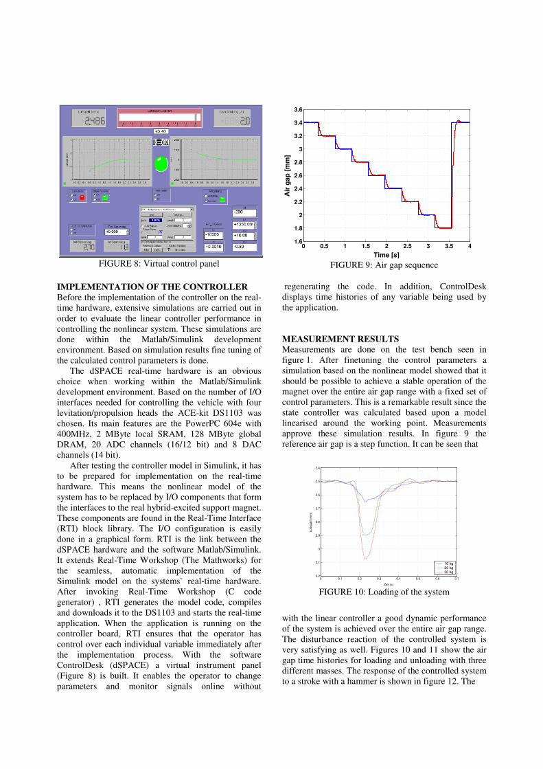
FIGURE 8: Virtual control panel FIGURE 9: Air gap sequence
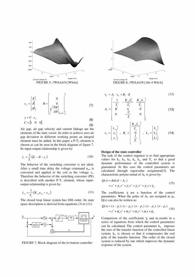
IMPLEMENTATION OF THE CONTROLLER
Before the implementation of the controller on the real-time hardware, extensive simulations are carried out in order to evaluate the linear controller performance in controlling the nonlinear system. These simulations are done within the Matlab/Simulink development environment. Based on simulation results fine tuning of the calculated control parameters is done.
The dSPACE real-time hardware is an obvious choice when working within the Matlab/Simulink development environment. Based on the number of I/O interfaces needed for controlling the vehicle with four levitation/propulsion heads the ACE-kit DS1103 was chosen. Its main features are the PowerPC 604e with 400MHz, 2 MByte local SRAM, 128 MByte global DRAM, 20 ADC channels (16/12 bit) and 8 DAC channels (14 bit).
After testing the controller model in Simulink, it has to be prepared for implementation on the real-time hardware. This means the nonlinear model of the system has to be replaced by I/O components that form the interfaces to the real hybrid-excited support magnet. These components are found in the Real-Time Interface (RTI) block library. The I/O configuration is easily done in a graphical form. RTI is the link between the dSPACE hardware and the software Matlab/Simulink. It extends Real-Time Workshop (The Mathworks) for the seamless, automatic implementation of the Simulink model on the systems` real-time hardware. After invoking Real-Time Workshop (C code generator) , RTI generates the model code, compiles and downloads it to the DS1103 and starts the real-time application. When the application is running on the controller board, RTI ensures that the operator has control over each individual variable immediately after the implementation process. With the software ControlDesk (dSPACE) a virtual instrument panel (Figure 8) is built. It enables the operator to change parameters and monitor signals online without
regenerating the code. In addition, ControlDesk displays time histories of any variable being used by the application. MEASUREMENT RESULTS
Measurements are done on the test bench seen in figure 1. After finetuning the control parameters a simulation based on the nonlinear model showed that it should be possible to achieve a stable operation of the magnet over the entire air gap range with a fixed set of control parameters. This is a remarkable result since the state controller was calculated based upon a model linearised around the working point. Measurements approve these simulation results. In figure 9 the reference air gap is a step function. It can be seen that
0 0.1 0.2 0.3 0.4 0.5 0.6 0.7
2.4
2.5
2.6
2.7
2.8
2.9
3
3.1
3.2
Zeit (s)
Lu
ftsp
alt (
mm
)
10 kg20 kg30 kg
FIGURE 10: Loading of the system
with the linear controller a good dynamic performance of the system is achieved over the entire air gap range. The disturbance reaction of the controlled system is very satisfying as well. Figures 10 and 11 show the air gap time histories for loading and unloading with three different masses. The response of the controlled system to a stroke with a hammer is shown in figure 12. The
0 0.5 1 1.5 2 2.5 3 3.5 41.6
1.8
2
2.2
2.4
2.6
2.8
3
3.2
3.4
3.6
Time [s]
Air
ga
p [
mm
]
0 0.1 0.2 0.3 0.4 0.5 0.6 0.7
1.4
1.6
1.8
2
2.2
2.4
2.6
2.8
Zeit (s)
Luftspalt (
mm
)
10 kg20 kg30 kg
FIGURE 11: Unloading of the system
0 0.2 0.4 0.6 0.8 1 1.2 1.4 1.6 1.8 20
0.5
1
1.5
2
2.5
3
3.5
Luftspalt(m
m)
Zeit (s)0 0.2 0.4 0.6 0.8 1 1.2 1.4 1.6 1.8 2
−1500
−1000
−500
0
500
1000
1500
2000
2500
3000
3500
4000
Durc
hflutu
ng (
A)
FIGURE 12: Response to a blow with a hammer
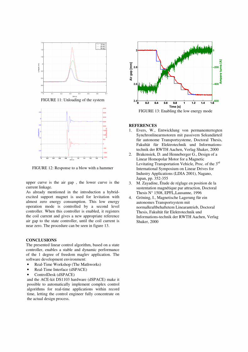
upper curve is the air gap , the lower curve is the current linkage. As already mentioned in the introduction a hybrid-excited support magnet is used for levitation with almost zero energy consumption. This low energy operation mode is controlled by a second level controller. When this controller is enabled, it registers the coil current and gives a new appropriate reference air gap to the state controller, until the coil current is near zero. The procedure can be seen in figure 13. CONCLUSIONS
The presented linear control algorithm, based on a state controller, enables a stable and dynamic performance of the 1 degree of freedom maglev application. The software development environment: • Real-Time Workshop (The Mathworks) • Real-Time Interface (dSPACE) • ControlDesk (dSPACE) and the ACE-kit DS1103 hardware (dSPACE) make it possible to automatically implement complex control algorithms for real-time applications within record time, letting the control engineer fully concentrate on the actual design process.
0 0.2 0.4 0.6 0.8 1 1.2 1.4 1.62.4
2.6
2.8
3
Air
ga
p [
mm
]
0 0.2 0.4 0.6 0.8 1 1.2 1.4 1.6−600
−400
−200
0
Time [s]
Am
pe
re t
urn
s [
A]
FIGURE 13: Enabling the low energy mode
REFERENCES 1. Evers, W., Entwicklung von permanenterregten
Synchronlinearmotoren mit passivem Sekundärteil für autonome Transportsysteme, Doctoral Thesis, Fakultät für Elektrotechnik und Informations-technik der RWTH Aachen, Verlag Shaker, 2000
2. Brakensiek, D. and Henneberger G., Design of a Linear Homopolar Motor for a Magnetic Levitating Transportation Vehicle, Proc. of the 3rd
International Symposium on Linear Drives for Industry Applications (LDIA 2001), Nagano, Japan, pp. 352-355
3. M. Zayadine, Étude de réglage en position de la sustentation magnétique par attraction, Doctoral Thesis N° 1508, EPFL,Lausanne, 1996
4. Gröning, I., Magnetische Lagerung für ein autonomes Transportsystem mit normalkraftbehaftetem Linearantrieb, Doctoral Thesis, Fakultät für Elektrotechnik und Informations-technik der RWTH Aachen, Verlag Shaker, 2000
