design and implementation of a dsp-based control interface
TRANSCRIPT

Calhoun: The NPS Institutional Archive
Theses and Dissertations Thesis Collection
2004-03
Design and implementation of a DSP-based control
interface unit (CIU)
Kavousanos-Kavousanakis, Andreas
Monterey, California. Naval Postgraduate School
http://hdl.handle.net/10945/1664

NAVAL POSTGRADUATE
SCHOOL
MONTEREY, CALIFORNIA
THESIS
Approved for public release; distribution is unlimited
DESIGN AND IMPLEMENTATION OF A DSP-BASED CONTROL INTERFACE UNIT (CIU)
by
Andreas Kavousanos-Kavousanakis
March 2004
Thesis Advisor: Xiaoping Yun Second Reader: David C. Jenn

THIS PAGE INTENTIONALLY LEFT BLANK

i
REPORT DOCUMENTATION PAGE Form Approved OMB No. 0704-0188 Public reporting burden for this collection of information is estimated to average 1 hour per response, including the time for reviewing instruction, searching existing data sources, gathering and maintaining the data needed, and completing and reviewing the collection of information. Send comments regarding this burden estimate or any other aspect of this collection of information, including suggestions for reducing this burden, to Washington headquarters Services, Direc-torate for Information Operations and Reports, 1215 Jefferson Davis Highway, Suite 1204, Arlington, VA 22202-4302, and to the Office of Management and Budget, Paperwork Reduction Project (0704-0188) Washington DC 20503. 1. AGENCY USE ONLY (Leave blank)
2. REPORT DATE March 2004
3. REPORT TYPE AND DATES COVERED Master’s Thesis
4. TITLE AND SUBTITLE: Design and Implementation of a DSP-Based Control Interface Unit (CIU) 6. AUTHOR(S) Andreas Kavousanos-Kavousanakis
5. FUNDING NUMBERS
7. PERFORMING ORGANIZATION NAME(S) AND ADDRESS(ES) Naval Postgraduate School Monterey, CA 93943-5000
8. PERFORMING ORGANIZATION REPORT NUMBER
9. SPONSORING / MONITORING AGENCY NAME(S) AND ADDRESS(ES)
U.S. Army Research Office (ARO) U.S. Navy Modeling and Simulation Office (N6M)
10. SPONSORING / MONITORING AGENCY REPORT NUMBER
11. SUPPLEMENTARY NOTES The views expressed in this thesis are those of the author and do not reflect the official policy or position of the Department of Defense or the U.S. Government. 12a. DISTRIBUTION / AVAILABILITY STATEMENT Approved for public release; distribution is unlimited.
12b. DISTRIBUTION CODE
13. ABSTRACT (maximum 200 words) This research involves the development of a human-body motion tracking system constructed with the use of
commercial off-the-shelf (COTS) components. The main component of the system investigated in this thesis is the Con-
trol Interface Unit (CIU). The CIU is a component designed to receive data from the magnetic, angular rate, and gravity
(MARG) sensors and prepare them to be transmitted through a wireless configuration. A simple and effective algorithm
is used to filter the sensor data without singularities, providing the measured attitude in the quaternion form for each
human limb. Initial calibration of the MARG sensors is also performed with the use of linear calibrating algorithms. The
testing and evaluation of the whole system is performed by MATLAB® and SIMULINK® simulations, and by the real-
time visualization using a human avatar designed with the X3D graphics specifications.
Through this research, it is discovered that the MARG sensors had to be redesigned to overcome an erratum
on the Honeywell magnetometer HMC1051Z data sheet. With the redesigned MARG sensors, the testing results
showed that the CIU was performing extremely well. The overall motion tracking system is capable of tracking human
body limb motions in real time.
15. NUMBER OF PAGES
86
14. SUBJECT TERMS MARG III Sensor, Control Interface Unit (CIU), One-,Three-, Sixteen-Channel CIU, Avatar, Virtual Environment, Virtual Training, Immersion, Honeywell, Analog Devices, Texas Instruments, Microcontroller, Micromachined Sensor, X3D, Java, Xilinx, RS232, Wireless Communication, WiSER 2400. 16. PRICE CODE
17. SECURITY CLASSIFICA-TION OF REPORT
Unclassified
18. SECURITY CLASSIFICA-TION OF THIS PAGE
Unclassified
19. SECURITY CLAS-SIFICATION OF AB-STRACT
Unclassified
20. LIMITATION OF ABSTRACT
UL NSN 7540-01-280-5500 Standard Form 298 (Rev. 2-89) Prescribed by ANSI Std. 239-18

ii
THIS PAGE INTENTIONALLY LEFT BLANK

iii
Approved for Public Release; Distribution is Unlimited
DESIGN AND IMPLEMENTATION OF A DSP-BASED CONTROL INTERFACE UNIT (CIU)
Andreas Kavousanos-Kavousanakis
Lieutenant Junior Grade, Hellenic Navy B.S. in Naval Science, Hellenic Naval Academy, 1997
B.S. Equivalency in Electrical Engineering, Naval Postgraduate School, 2002
Submitted in partial fulfillment of the requirements for the degree of
MASTER OF SCIENCE IN ELECTRICAL ENGINEERING and
MASTER OF SCIENCE IN SYSTEMS ENGINEERING
from the
NAVAL POSTGRADUATE SCHOOL March 2004
Author: Andreas Kavousanos-Kavousanakis Approved by: Xiaoping Yun
Thesis Advisor
David C. Jenn Second Reader
John P. Powers Chairman, Department of Electrical and Computer Engineering
Dan C. Boger Chairman, Department of Information Science

iv
THIS PAGE INTENTIONALLY LEFT BLANK

v
ABSTRACT
This research involves the development of a human-body motion tracking
system constructed with the use of commercial off-the-shelf (COTS) compo-
nents. The main component of the system investigated in this thesis is the Con-
trol Interface Unit (CIU). The CIU is a component designed to receive data from
the magnetic, angular rate, and gravity (MARG) sensors and prepare them to be
transmitted through a wireless configuration. A simple and effective algorithm is
used to filter the sensor data without singularities, providing the measured atti-
tude in the quaternion form for each human limb. Initial calibration of the MARG
sensors is also performed with the use of linear calibrating algorithms. The test-
ing and evaluation of the whole system is performed by MATLAB® and SIMU-
LINK® simulations, and by the real-time visualization using a human avatar de-
signed with the X3D graphics specifications.
Through this research, it is discovered that the MARG sensors had to be
redesigned to overcome an erratum on the Honeywell magnetometer HMC1051Z
data sheet. With the redesigned MARG sensors, the testing results showed that
the CIU was performing extremely well. The overall motion tracking system is
capable of tracking human body limb motions in real time.

vi
THIS PAGE INTENTIONALLY LEFT BLANK

vii
TABLE OF CONTENTS I. INTRODUCTION........................................................................................1
A. PREVIOUS WORK ON THE MARG SENSOR ...............................1 B. RESEARCH ISSUES ......................................................................2 C. THESIS GOALS..............................................................................4 D. THESIS ORGANIZATION OUTLINE ..............................................4 E. SUMMARY......................................................................................5
II. THE MARG III SENSOR............................................................................7 A. PERFORMANCE REQUIREMENTS...............................................7 B. THE HONEYWELL HMC1051Z/HMC1052 ONE- AND TWO-AXIS
MAGNETIC SENSORS...................................................................8 1. Particularities for the MARG III Design ...........................10
C. THE ANALOG DEVICES ADXL202E TWO-AXIS ACCELERATION SENSOR..........................................................10 1. Defining the Bandwidth and the DCM (Duty-Cycle
Modulation) Period of the Sensor ...................................12 2. Particularities for the MARG III Design ...........................12
D. THE TOKIN CG-L43 CERAMIC GYRO ........................................13 E. THE TEXAS INSTRUMENTS MSP430F149
MICROCONTROLLER..................................................................14 F. THE MARG III MAGNETIC, ANGULAR RATE AND GRAVITY
SENSOR AS AN ENTITY .............................................................16 G. SUMMARY....................................................................................17
III. THE CONTROL INTERFACE UNIT (CIU) ...............................................19 A. PURPOSE OF THE CONTROL INTERFACE UNIT .....................19 B. THE ONE-CHANNEL CONTROL INTERFACE UNIT (ONE-
CHANNEL CIU) ............................................................................20 C. THE THREE-CHANNEL CONTROL INTERFACE UNIT (THREE-
CHANNEL CIU) ............................................................................23 D. THE SIXTEEN-CHANNEL CONTROL INTERFACE UNIT
(SIXTEEN-CHANNEL CIU)...........................................................24 E. SUMMARY....................................................................................27
IV. FIRMWARE UPLOADING AND CALIBRATION.....................................29 A. UPLOADING THE FIRMWARE ....................................................29
1. Preparing the Workbench – Firmware Upload ...............32 B. THE CALIBRATION PROCEDURE..............................................36
1. Validation of Calibration Results.....................................38 2. Results – MARG III Sensor Redesign..............................39
C. SUMMARY....................................................................................43
V. VISUALIZATION OF THE MARG III SENSOR DATA.............................45 A. THE QUEST ALGORITHM ...........................................................45 B. MATLAB® AND SIMULINK® SIMULATIONS .............................46

viii
C. REAL-TIME VISUALIZATION OF THE SENSOR DATA .............51
VI. CONCLUSIONS AND FURTHER WORK................................................57 A. THESIS CONTRIBUTIONS...........................................................57 B. FURTHER DEVELOPMENT .........................................................58
LIST OF REFERENCES.....................................................................................61
INITIAL DISTRIBUTION LIST ............................................................................65

ix
LIST OF FIGURES Figure 1. The MARG Project Overview [From Ref. 1.]. .................................2 Figure 2. The Honeywell Magnetic Sensors HMC1051Z and HMC1052
[From Ref. 5.]. ..................................................................................9 Figure 3. The ADXL202E Two-axis Acceleration Sensor [After Ref. 7.]....11 Figure 4. Functional Block Diagram of ADXL202E Acceleration Sensor
[After Ref. 6.]. .................................................................................11 Figure 5. Polarity Convention and Coordinate System Definition on
ADXL202E Acceleration Sensor [From Ref. 6.]. ..........................13 Figure 6. The CG-L43 and CG-L53 Ceramic Gyros [After Ref. 8.]..............14 Figure 7. Top (left) and Bottom (right) View of the Manufactured MARG III
Prototype [After Ref. 9.]. ...............................................................16 Figure 8. The Manufactured MARG III Unit (Compared to a Dime)............17 Figure 9. The One-channel Control Interface Unit (One-channel CIU)......21 Figure 10. Bottom View of the One-channel Control Interface Unit (One-
channel CIU)...................................................................................22 Figure 11. The MARG III – CIU Schematic [After Ref. 14.]. ...........................22 Figure 12. The Three-channel Control Interface Unit (Three-channel CIU).23 Figure 13. Top View of the Sixteen-channel Control Interface Unit (Sixteen-
channel CIU)...................................................................................24 Figure 14. Bottom View of the Sixteen-channel Control Interface Unit
(Sixteen-channel CIU)....................................................................25 Figure 15. The Texas Instruments MSP-FET430P140 Development Tool
[From Ref. 17.]. ..............................................................................31 Figure 16. The Configuration Used to Program the Microcontrollers.........31 Figure 17. Options Menu on the IAR Embedded Workbench. .....................32 Figure 18. General Submenu in the Options Menu.......................................33 Figure 19. ICC430 Submenu in the Options Menu........................................33 Figure 20. A430 Submenu in the Options Menu. ..........................................34 Figure 21. XLINK Submenu in the Options Menu. ........................................34 Figure 22. C-SPY Submenu in the Options Menu. ........................................35 Figure 23. Debugging and Uploading the Firmware.....................................35 Figure 24. The HAAS Tilting/Rotating Table. ................................................37 Figure 25. Calibration Results for x: North, y: Up, z: East, Rotation about z.
........................................................................................................40 Figure 26. Earth’s Magnetic Field Lines [From Ref. 18.]. .............................41 Figure 27. Calibration Results for x: East, y: Down, z: North, Rotation
about x............................................................................................43 Figure 28. The SIMULINK® Model Created to Visualize the Results...........47 Figure 29. The Block Diagram of the QUEST Algorithm ..............................48 Figure 30. The SIMULINK® Rigid Body Missile. ...........................................50 Figure 31. Euler Angles for a Pattern 2 Motion. ............................................50 Figure 32. Left Lower Arm Avatar Created in X3D Format...........................52 Figure 33. The X3D Human Avatar. ................................................................52

x
Figure 34. Real-time Projection of a Human Arm Motion Using Two MARG III Sensors. .....................................................................................54
Figure 35. Real-time Projection of a Human Arm Motion Using Two MARG III Sensors. .....................................................................................54

xi
LIST OF TABLES Table 1. Filter Capacitor Selection Cx and Cy [From Ref. 6.].....................12 Table 2. The Sixteen-channel CIU Output Byte-format.............................26

xii
THIS PAGE INTENTIONALLY LEFT BLANK

xiii
ACKNOWLEDGMENTS
Funding for the project was provided by the U.S. Army Research Office
(ARO) and the U.S. Navy Modeling and Simulation Office (N6M). Without their
support, we would not have had the necessary means to fulfill our goals, and this
research would have never been completed.
I strongly feel that I owe everything I have accomplished in my life to my
parents Georgios Kavousanos-Kavousanakis and Aliki Kavousanou-Kavousa-
naki. I would like to thank them for their constant guidance and support through
my whole life. It was their endless love, care, and encouragement that enabled
me to overcome any obstacles that I ever encountered.
It was Alexander the Great (356-323 BC) who said about his Teacher Aris-
totle that: “I am indebted to my Parents for Living, but to my Teacher for Living
Well”. With this quote in mind, I would like to express my gratitude to my teacher
and thesis advisor Professor Xiaoping Yun for his help and tireless support dur-
ing the difficulties that I came across in my research. His brilliance guided me all
the time to pursuit the appropriate paths in order to fulfill my ultimate goal: the
creation of a unique motion tracking system.
I have to admit that the hardest part of my thesis was to have everything
achieved, written down in a foreign language to me, and in such way that any-
body would be able to understand. Even though Dr. Yun’s native language is
Chinese, I was completely amazed by the wealth of his knowledge in English.
I would like to thank Professor Robert G. Hutchins for passing me large
fragments of his knowledge in the topic of quaternions, which is a topic extremely
important to my research.
I would also like to thank James Calusdian for all his help in the lab. He
was extremely helpful at the times an instrument and tool expert was needed.
My brothers Kostas and Christos, even though so far from me, helped me
through many personal difficulties. Thank you for being there for me.

xiv
The two years I spent in Monterey studying for my degrees would have
been totally different without Bridget Bevin. Bridget is the one who showed me
what it is really like to live in the United States and she immersed me in a world
that I wouldn’t have understood otherwise. Thank you for being there for me at all
times.
Many thanks to Faruk Yildiz for the hours and the combined effort we
made together in order to complete our research. Faruk, our efforts finally paid
off.
I would also like to thank Ron Russell for his meticulous and speedy edit-
ing of this thesis. His efficient work was extremely helpful to me.
Finally, I would like to thank Doug McKinney for putting up with me and my
whining, over our endless phone and email conversations. Thank you for trusting
my recommendations about the MARG III sensors.

xv
«Εἰς τούς Γονεῖς µου χρεωστῶ τό Ζῆν, εἰς τόν Διδάσκαλό µου τό Εὖ Ζῆν» I am indebted to my Parents for Living, but to my Teacher for Living Well
—Alexander the Great (356-323 BC)

xvi
To my Lovely Bridget

xvii
EXECUTIVE SUMMARY
This research involved the development of a human body motion-tracking
system constructed with the use of commercial off-the-shelf (COTS) compo-
nents. This system was initiated to implement a Synthetic Environment (SE) for
Virtual Combat Training purposes. The main characteristic of a successful SE is
the depth of the immersion that the users of the SE achieve. The deeper the im-
mersion, the more effective the Synthetic Environment is.
The main component of the system investigated in this thesis was the
Control Interface Unit (CIU). The CIU is a component designed to receive data
from the magnetic, angular rate, and gravity (MARG) sensors and prepare them
to be transmitted through a wireless configuration. A simple and effective algo-
rithm was used to filter the sensor data without singularities, providing the meas-
ured attitude in the quaternion form for each human limb. Initial calibration of the
MARG sensors was also performed with the use of linear calibrating algorithms.
The testing and an evaluation of the whole system was performed by MATLAB®
and SIMULINK® simulations and by real-time visualization using a human avatar
designed with the X3D graphics specifications.
The MARG sensor used in this research is the third generation of the
MARG sensors, called the MARG III sensors. Designed for low power-
consumption and size/weight minimization, the MARG III sensors consist of nine
micromachined magnetic, angular rate and gravity sensors. The MARG III sen-
sors are programmed to provide measurements with a sampling rate of 100 Hz.
The development of the CIU was completed in stages. First, a one-
channel CIU was designed and implemented to handle the data delivered by one
MARG III sensor. With this CIU, the MARG system was tested for end-to-end
data handling, including data acquisition, data delivery, and wireless data trans-
mission from the MARG III sensor to the 3D projection on a remote screen. Next,
the three-channel CIU was developed to test the system’s capability of handling

xviii
data from multiple MARG III sensors. Finally, the sixteen-channel CIU was de-
signed to facilitate sixteen MARG III sensors. The sixteen-channel CIU is in its
final steps of development.
Calibration of the data received by the CIU is performed by linear calibrat-
ing algorithms. Precise rotations of the sensors to ensure accurate calibration are
performed with the use of a HAAS tilting/rotating table.
The data filtering algorithm chosen is the QUEST algorithm. Already
tested in various satellite tracking applications, the QUEST algorithm ensures
real-time, efficient data filtering without any singularities. Moderate modifications
in the algorithm were made to improve the accuracy of the output with minimal
effects in the efficiency of the algorithm.
Through this research, it was discovered that the MARG III sensors had to
be redesigned to overcome an erratum on the Honeywell magnetometer
HMC1051Z data sheet. With the redesigned MARG III sensors, the testing re-
sults showed that the CIU is performing extremely well. The overall motion-
tracking system is capable of tracking human body limb motions in real time.
The current system tracks a slow moving human body accurately. All of
the experimental results have indicated that after the completion of the sixteen-
channel CIU and the complementary filter, the system will be capable of tracking
fifteen human limbs accurately. Visual representation and, thus immersion into
the Virtual Environment, can be achieved without any of the limitations of the
previous version of MARG sensors (the MARG II sensors). The 100-Hz sampling
rate has proved sufficient for real-time tracking of human body motion. Imple-
menting the system for immersion of more than one user into the same Synthetic
Environment will also be possible.

1
I. INTRODUCTION
This chapter discusses the general concept of the MARG project. A brief
discussion about the previous work on the project is given, followed by research
issues to be addressed in this thesis. Furthermore, a brief outline of the remain-
ing thesis chapters is presented.
A. PREVIOUS WORK ON THE MARG SENSOR The MARG project is an ongoing effort to achieve the full representation of
the motion of the human body into a virtual environment, often called a Synthetic
Environment [Ref. 1]. To be more accurate, the design goal of a Synthetic Envi-
ronment is to make its users feel as if they really exist in that environment. There-
fore a more accurate word than representation is immersion. The deeper the im-
mersion, the more effective the Synthetic Environment is.
The MARG project was designed to implement a Synthetic Environment
for Virtual Combat Training purposes. Therefore, especially in this case, the
depth of the immersion is of crucial importance.
An early attempt to create an immersive environment was conducted by
Bachman [Ref. 2]. In this dissertation the design of the second generation of a
prototype sensor called MARG II (Magnetic, Angular Rate, and Gravity) was de-
scribed. One MARG II sensor was placed on each human limb to monitor its
three-degrees-of-freedom motion. The MARG II sensors consisted of three mag-
netometers, three accelerometers, and three angular rate micromachined sen-
sors. They were cabled to a central computer, which was used to gather and filter
the analog data transmitted from the MARG II sensors and to visually represent
the motion of each limb on a human avatar. The system is depicted in Figure 1.

2
B. RESEARCH ISSUES The MARG II sensor was not without some drawbacks. First, it was pow-
ered by a 12-Volt DC battery, which was enclosed in the casing of the sensor,
significantly increasing its size and weight. The power consumption was signifi-
cant. Therefore, in order to implement a full body motion-tracking system, a suffi-
cient number of battery cells needed to be carried along.
Figure 1. The MARG Project Overview [From Ref. 1.].
Furthermore, the whole structure of the MARG II sensor was based on a
single computer that handled all the processes of receiving, sorting, filtering and
visually representing the data received from each sensor. A single failure on that
computer would totally disrupt the operation of the whole system. If another com-
puter was chosen to replace the original one, a time consuming process of in-
stalling drivers and moving bulky hardware from one computer to another would
have to occur before the system was again operational. The system performance
depended solely on the performance of only one processor.
Another drawback of the MARG II sensor was the permanent attachment
of the user to the central computer through the sensor cables, as seen in Figure
1.

3
Removing the cables from the sensors was cumbersome, since transmit-
ting data wirelessly from all nine data channels for each of the MARG sensors (a
total of 135 channels for all 15 MARG sensors) was quite difficult to implement. If
the data were in digital format, a multiplexing technique could be used.
The following summarizes the challenges that must be overcome in order
to transform the MARG sensor into an easily deployed system:
• Reducing the size and weight,
• Minimizing power consumption,
• Extricating the tracked object from the central computer using wireless
transmission,
• Replacing components easily, and finally,
• Decentralizing the computational processes from one central computer
to networked multiple components for increased performance and surviv-
ability of the system.
In order to resolve the above challenges, the MARG III project was initi-
ated, and the entire system was completely redesigned. The prototype MARG
sensors were replaced by a new generation of smaller programmable units, the
MARG III sensors. A new component called the Control Interface Unit (CIU) was
introduced to remove some of the processing load from the central computer,
and also to manipulate the digital data provided by the MARG III sensors and
prepare them to be transmitted serially, through a wireless infrastructure. Addi-
tionally, the CIU was designed to distribute power to all the sensors from a cen-
tral battery cell, removing the extra load of a battery from each individual MARG
sensor. The sensors and the CIU were designed with low-power consuming
components, increasing the durability of the battery cell.
A computer functioning as a server replaced the central computer. This
server is capable of establishing a layer 4 (in the OSI model) TCP/IP connection
for the initial communication (handshake) between a wireless transmitter, at-

4
tached to the CIU, and the server. For the actual data flow, a UDP connection is
established since real-time data transmission is required. Furthermore, a loss of
data packets is not a serious issue in real-time applications in which the data-
transmission rate is high enough to overcome those losses.
Finally, for the data representation, another computer was chosen to im-
plement the client, visualizing the body-motion tracking on an avatar designed by
using the X3D standard.
C. THESIS GOALS
The main goal of this thesis was to design and to implement the Control
Interface Unit (CIU) within the proposed MARG III project and to embed it into the
whole MARG III system, which requires the following to be achieved:
• Gather data from the MARG III sensors,
• Feed them to the CIU,
• Transmit them wirelessly to the server,
• Implement a filter to transform the data into rotation angles, and finally,
• Visualize the results on a human avatar.
Due to the extent of the MARG III project effort, this thesis was conducted
in parallel with another thesis [Ref. 3], which focuses on a 3-D representation of
the motion of the human body.
D. THESIS ORGANIZATION OUTLINE
Chapter II presents the MARG III sensor and its components. A brief dis-
cussion reveals the reasons those components were chosen. Particularities con-
cerning the MARG III sensor are addressed.

5
Chapter III analyzes the Control Interface Unit (CIU). The one- and three-
channel CIU and their components are described. The concept of the sixteen-
channel CIU is introduced along with the benefits of its implementation.
Chapter IV describes the procedure of uploading the firmware to the
MARG III sensor and the CIU. The concept of calibrating the sensors is dis-
cussed and the calibrating procedure is described. MATLAB® and SIMULINK®
simulations that verify the calibration results are also discussed.
Chapter V conducts the evaluation and testing of the CIU as a functioning
part of the whole MARG III project. The QUEST algorithm is used to filter the
data delivered by the CIU. Necessary modifications to the algorithm are pre-
sented. Finally, combining this thesis work with another thesis [Ref. 3], in an ef-
fort to produce a complete MARG III system, is discussed.
The final chapter of this thesis presents conclusions and suggestions for
further development and optimization of the results.
E. SUMMARY In this chapter, the history of the MARG project is discussed along with the
drawbacks of the existing MARG sensors and the proposals to overcome those
drawbacks. The goals of this thesis were also discussed. Finally a brief summary
of the remaining chapters was presented.

6
THIS PAGE INTENTIONALLY LEFT BLANK

7
II. THE MARG III SENSOR
This chapter provides a brief discussion of the MARG III sensor and its
components. The MARG III sensor consists of three accelerometers, three mag-
netometers, three rate sensors, and a Texas Instruments (TI) microcontroller.
The three accelerometers form an orthogonal triad and so do the three
magnetometers and rate sensors. The three different triads are placed on the
sensor’s Printed Circuit Board (PCB) forming three right-handed coordinate sys-
tems. All of the sensor triads are aligned with each other. Therefore, the orienta-
tion of the accelerometer pointing in the positive x-axis coincides with those of
the magnetometer and the rate sensor pointing in the positive x-axis. The sen-
sors pointing in the positive y- and z-axis follow the same convention, yielding a
right-handed coordinate system body frame for the designed MARG III sensor.
A. PERFORMANCE REQUIREMENTS In order to justify the reason for choosing each of the components, a brief
analysis of the human body motion is presented below.
The fact that the human arm is the fastest moving human limb is com-
monly known. Therefore if the limits satisfy the arm’s performance requirements,
then all other limb limitations will also be satisfied. Normally, the maximum tan-
gential speed that a human wrist can accomplish is no greater than 3 m/sec and
its maximum acceleration fluctuates between 5 and 6 g [Ref. 2]. A grenade
throwing motion, which is a classic case of a really fast arm motion, is usually
achieved with tangential velocities greater than 35 m/sec and accelerations of
more than 25 g [Ref. 2]. The bandwidth occupied by the normal arm motion is
estimated to be close to 2 Hz, whereas faster motions may spread the bandwidth
to approximately 5 to 6 Hz. When the human arm moves as a result of a neuro-
muscular reflex motion, then a 10-Hz approximation of the bandwidth is consid-

8
ered to be accurate [Ref. 2, 4]. Therefore, the sampling rate required to avoid
aliasing according to the Nyquist theorem should be 20 Hz.
Furthermore, the components of the project, especially the sensors, are
expected to be susceptible to noise. Therefore, the computed sampling rate is
multiplied by a safety factor. Following a general rule of thumb of oversampling
20 times, aliasing will be avoided [Ref. 2]. This results in a sampling rate of 200
Hz for the 10 Hz bandwidth of the reflex motions. The normal human motion of 5
Hz bandwidth results in a sampling rate of 100 Hz, which is implemented in the
MARG III sensor. With the above in mind, the following components were chosen
for the MARG III sensor.
B. THE HONEYWELL HMC1051Z/HMC1052 ONE- AND TWO-AXIS MAG-NETIC SENSORS The following material is mainly taken from [Ref. 5].
Honeywell has created a family of one-, two-, and three-axis magnetic
sensors. At the time the MARG III was designed, the three-axis magnetic sensor
was not yet available. Therefore in the MARG III design, a pair of the two-axis
(HMC1052) and one-axis (HMC1051Z) magnetic sensors was chosen for x- and
y-axes and z-axis, respectively, to create the magnetic sensor triad. The dimen-
sions of the one-axis HMC1051Z are 6.850 x 9.829 x 1.371 mm, whereas those
of the two-axis HMC1052 are 4.75 x 2.90 x 1.10 mm. A magnified view of the two
sensors is shown in Figure 2.
Although the two-axis magnetic sensor is smaller in dimension than the
one-axis one, a pair of a HMC1052 and a HMC1051Z proved most suitable be-
cause Honeywell has designed them to create an orthogonal triad when mounted
on the same PCB [Ref. 5].

9
Figure 2. The Honeywell Magnetic Sensors HMC1051Z and HMC1052 [From Ref. 5.].
The sensors are designed as 4-element Wheatstone bridges, which are
capable of converting very low magnetic fields to differential voltages. In fact they
can detect magnetic fields of only 120 µgauss in strength.
Besides the bridge circuit, the HMC1051Z and HMC1052 micromachined
magnetoresistive sensors have two onboard magnetically-coupled straps, the off-
set strap and the set-reset strap.
The purpose of the offset strap, attached to the entire circuit, is to provide
different modes of operation such as:
• Eliminating the unwanted magnetic fields residing in the area where
the sensor operates,
• Nulling the bridge offset voltage,
• Canceling the closed-loop field, and finally,
• Auto calibrating the bridge gain.
In most applications (including MARG III) the offset strap is not used.
Therefore the offset strap connections have been left open-circuited, as sug-
gested by Honeywell [Ref. 5].
The set-reset strap, when driven properly, provides the sensor with a po-
larity flip of the Wheatstone bridge output voltage (and therefore north-south flip).

10
A “set pulse” is defined as a positive pulse current of approximately 400
mA over the nominal resistance of 3 to 6 ohms that the strap provides, when ap-
plied on the set-reset positive strap connection. On the other hand, a “reset
pulse” is defined as a negative pulse current of approximately 400 mA, applied
also on the set-reset positive strap connection. When applying a reset pulse, the
magnetic domains produce negative voltages across the output connections. A
set pulse does exactly the opposite, and when applied following the order reset-
set within a few milliseconds, the magnetic domains reverse their direction twice,
thereby canceling any prior remaining magnetic fields that may reside on them.
1. Particularities for the MARG III Design Unfortunately, Honeywell designed the one- and two-axis magnetic sen-
sors to form a triad that follows the left-handed coordinate system. The two coor-
dinate systems (left- and right-handed) differ in the orientation of z-axis. There-
fore, in order to transform the coordinate system of the magnetic sensors from a
left-handed to a right-handed system, the orientation of the HMC1051Z, which
plays the role of the z-axis magnetometer, must be flipped.
One way to do this is by programming this sensor to set-reset periodically
instead of reset-set. That would result in a 180o z-axis flip. Another method is to
place the HMC1051Z upside down (belly up) on the PCB, so as to point to nega-
tive z instead of positive z. By doing that, the set-reset straps in both HMC1052
and HMC1051Z magnetometers are used in a coherent way (both of them in a
set-reset sequence). The latter is the solution chosen for the MARG III sensor.
C. THE ANALOG DEVICES ADXL202E TWO-AXIS ACCELERATION SENSOR The following material is mainly taken from [Ref. 6].
The accelerometers chosen for the MARG III design were the micro-
machined two-axis acceleration sensors ADXL202E from Analog Devices shown
in Figure 3 [Ref. 6]. They have a measurement range of static and dynamic ac-

11
celerations of 4 g (± 2 g), which was considered sufficient for measuring typical
human motions.
Figure 3. The ADXL202E Two-axis Acceleration Sensor [After Ref. 7.].
Their size is 4.50 x 5.00 x 1.78 mm. Since each chip can sense accelera-
tion in two orthogonal dimensions, only two of them are required in order to form
an orthogonal triad.
The block diagram of ADXL202E is shown in Figure 4, which illustrates
that this sensor is capable of providing both analog (from Cx and Cy capacitors)
and digital output (from Xout and Yout). When the Cx and Cy capacitors are not
used to drive the analog output, they can be used to determine the bandwidth of
the accelerometer. More information on the bandwidth will be presented later.
Figure 4. Functional Block Diagram of ADXL202E Acceleration Sensor [After Ref. 6.].
Analog Output
Digital Output
ADXL-202E

12
The digital output is represented by the duty cycle of the pulses created by
the oscillator, which is directly proportional to the combination of the dynamic and
static acceleration measured by the sensors.
The duty cycle is the ratio of the pulsewidth T1 over the period of the pulse
T2, and can be directly fed to a microcontroller along with T2, to recompute the
measured acceleration.
1. Defining the Bandwidth and the DCM (Duty-Cycle Modulation) Period of the Sensor
By choosing the correct values for capacitors Cx and Cy, the bandwidth of
the measurement can be defined. By doing that, low-pass filtering is achieved in
order to improve the measurement resolution and to help prevent aliasing [Ref.
6].
Table 1 lists the value of bandwidth for several values of Cx and Cy. The
minimum allowed value for Cx and Cy is 0.001 µF. For the MARG III sensor, the
Cx and Cy were chosen to be 0.027 µF, providing a bandwidth for the sensor out-
put of 200 Hz.
Table 1. Filter Capacitor Selection Cx and Cy [From Ref. 6.]. 2. Particularities for the MARG III Design
Figure 5 shows that, when an axis (e.g., x) is pointing down (negative 90o),
the sensor is configured to provide positive values of acceleration.

13
Figure 5. Polarity Convention and Coordinate System Definition on ADXL202E Acceleration Sensor [From Ref. 6.].
As mentioned previously in this chapter, the MARG III design follows the
right-handed coordinate system. Unfortunately, the triad formed by the pair of the
two ADXL202E follows the left-handed coordinate system. In order to overcome
this problem, the accelerometers were placed upside down on the MARG III PCB
yielding a right-handed coordinate system.
This orientation endowed the MARG III with a particularity. When an axis
(e.g., x) is pointing down (tilted 90o from the horizontal plane toward the ground),
the output of the corresponding gravity sensor is a positive 1 g. Similarly, when
pointing up, the output is a negative 1 g.
D. THE TOKIN CG-L43 CERAMIC GYRO The following material is mainly taken from [Ref. 8].
The rate sensor chosen for the MARG III design was the CG-L43 ceramic
gyro designed by NEC/TOKIN. It is a miniature, high-speed response, magnetic
field-proof sensor. This gyro consists of a single piezoelectric ceramic column
printed with electrodes, which when supplied with +3 V, can detect a maximum
angular rate of ± 90 deg/sec, at a nominal ambient temperature of 25o C [Ref. 8].
With dimensions of 8 x 16 x 5 mm, the CG-L43 was the smallest rate sen-
sor available on the market at the time the MARG III was designed. Today,
NEC/TOKIN offers the next generation of ceramic gyros CG-L53, with dimen-
sions 6 x 10 x 2.5 mm. Keeping in mind that these gyros are in fact the bulkiest
component of the MARG III, substituting the CG-L43 for another sensor, probably

14
a CG-L53, will benefit the next versions of the MARG sensor by reducing its size
and weight. The CG-L43 and CG-L53 are shown in Figure 6.
Figure 6. The CG-L43 and CG-L53 Ceramic Gyros [After Ref. 8.].
Since the rate sensors are not used at this phase of the MARG III project,
they will not be discussed further. In this thesis the measurements from the mag-
netic sensors and the accelerometers are acquired, processed, and analyzed.
E. THE TEXAS INSTRUMENTS MSP430F149 MICROCONTROLLER Two of the three components of the MARG III (the magnetometers and the
rate sensors) produce analog data. Therefore, the MARG III needed another
component to implement the analog-to-digital conversion and to transmit the digi-
tal data to the CIU.
After an extensive trade-off analysis, the Texas Instruments MSP-
430F149 microcontroller was selected and incorporated into the sensor unit [Ref.
9]. It is an Ultra Low-Power 16-bit RISC architecture with a 125-ns Instruction-
Cycle Time and a hardware multiplier. It operates with a very low supply voltage
that can vary from 1.8 Volts to 3.6 Volts. It has three modes of operation [Ref.
10]:
• An Active Mode: 280 µΑ at 1 MHz, 2.2 Volts,
• A Standby Mode: 1.6 µΑ, and
• An Off Mode with RAM detention: 0.1 µΑ.
CG-L43
CG-L53

15
When designing the MARG III sensor, one of the tasks was how to con-
nect the three magnetometers, the three rate sensors and the three accelerome-
ters into one microcontroller. Among the 48 I/O pins of the MSP430F149 micro-
controller, eight pins are reserved for analog inputs and are designed to drive the
input of a 12-bit A/D converter [Ref. 11]. Therefore the six analog signals pro-
vided by the magnetometers and the rate sensors could be connected to six of
those eight I/O pins.
Furthermore, the digital output from the accelerometers could be inter-
faced to the three capture-compare registers of one of the two timer-modules
(Timers A3 and B7; the latter is being used in the MARG III design). Owing to this
combination, the need to use a more complicated microcontroller with at least 12
or 16 analog channels was avoided.
Another attractive feature of the MSP430F159 is the relatively large RAM
of 2 KB and the quite large memory of 60 KB+256 B (program and data, respec-
tively) [Ref. 10]. This gives the MARG III user the capability of writing code for the
microcontroller, testing it, improving it, and uploading it into the microcontroller’s
flash memory without any additional hardware changes. In an extreme case, if
something is found to be wrong in the hardware design of the MARG III, the mi-
crocontroller itself will not need to be modified; only new firmware that corre-
sponds to the changes will need to be uploaded.
Finally, the MSP430F149 offers two universal serial synchronous-
asynchronous communication interfaces (USART) that enable the microcontroller
to communicate with its subsequent units. These are the MSP430F149 inside the
CIU (communication between the MARG III and the one-channel CIU) and an
RS-232 module (communication between the one-channel CIU and the Wiser
2400 wireless transmitter). The microcontroller onboard the MARG III communi-
cates with the one-channel CIU by using the SPI Synchronous mode.

16
F. THE MARG III MAGNETIC, ANGULAR RATE AND GRAVITY SENSOR AS AN ENTITY After the MARG III sensor design was finalized, McKinney Technology
was contracted to fabricate the sensors.
The top and bottom views of the MARG III prototype boards are shown in
Figure 7, which shows how small the MARG III PCBs are compared to an Ameri-
can quarter.
Figure 7. Top (left) and Bottom (right) View of the Manufactured MARG
III Prototype [After Ref. 9.].
Figure 8 shows the top, bottom, and side views of the MARG III assem-
bled into a one-piece sensor unit.
The MSP430F149 The ADXL202E The CG-L43
The HMC1051Z The HMC1052

17
Figure 8. The Manufactured MARG III Unit (Compared to a Dime).
The dimensions of the MARG III are 28 x 30.5 x 17.3 mm. When placed
inside the box shown in Figure 8, its size becomes 31.75 x 30.2 x 23.8. Without
the box, it weighs approximately 8.5 grams (0.3 oz). It consumes 144 mW (20
mA) when powered with 7.2 Volts. It can operate within a range between 5.5 and
8 Volts. It provides nine digital outputs using 12-bit words with a sample rate of
100 Hz.
G. SUMMARY
This chapter discussed the MARG III components, their physical arrange-
ment aboard the sensor’s PCB, and their main characteristics. The performance
requirements for the micromachined sensors and the microcontroller were ana-
lyzed, and the final form of the MARG III sensor was presented.
In the following chapter the one- and three-channel Control Interface Unit
(one- and three-channel CIU) will be analyzed. The concept of the sixteen-

18
channel CIU will be presented along with the benefits of its implementation in the
system.

19
III. THE CONTROL INTERFACE UNIT (CIU)
Chapter II described the hardware design of the MARG III sensor. This
chapter discusses the Control Interface Unit (CIU). First, the purpose of using the
CIU is presented. Then a description of the one- and three-channel CIU is given.
Finally, the approach for designing and implementing a sixteen-channel CIU is
presented.
A. PURPOSE OF THE CONTROL INTERFACE UNIT The Control Interface Unit (CIU) was designed to remove part of the com-
putational load from the MARG II central computer, as mentioned in Chapter I.
The main purpose, though, was to prepare the MARG III data to be transmitted
wirelessly. In order for this to be achieved, multiplexing of the data from all nine
channels of each sensor was necessary.
The MARG II sensor was powered by an onboard battery cell. The MARG
III sensor has been designed with the goal of minimizing size and weight. There-
fore, the need for an external power supply emerged.
The data from the MARG III sensor must be multiplexed in order to be
sent serially through a single transmission channel. Furthermore, in order to
achieve the detachment of the MARG III sensors and the CIU from the rest of the
hardware components of the MARG III project, the serial data must be transmit-
ted wirelessly. Therefore, the CIU has to deliver the data in a format that is easy
to transmit wirelessly.
The MARG III sensor communicates with the CIU through a Universal
Synchronous Asynchronous Receiver Transmitter (USART) operating in the Syn-
chronous Peripheral Interface (SPI) mode. In this configuration the MARG III
sensor operates as a slave device whereas the CIU is the master device. This
means that the clock signal needed for synchronizing the data transmission has
to be delivered to the MARG III sensor by the CIU.

20
B. THE ONE-CHANNEL CONTROL INTERFACE UNIT (ONE-CHANNEL CIU) It was very difficult for all aforementioned functions to be achieved with a
single stage. Therefore, the CIU had to be designed and implemented in stages.
First, the MARG III data acquisition had to be achieved from a single MARG III
sensor. Then the data had to be forwarded through the wireless channel and re-
ceived by a server program capable of filtering the data. The visual representa-
tion of the data delivered by one MARG III sensor had to follow. Finally, the re-
maining goal was receiving and multiplexing the data from all sixteen MARG III
sensors.
For these reasons, the one-channel CIU was designed and implemented
first. A picture of the one-channel CIU is shown in Figure 9. The main component
of the one-channel CIU is a TI MSP430F149 microcontroller identical to the one
onboard the MARG III sensor. This microcontroller was chosen for the same rea-
sons it was included in the MARG III sensor design: low power consumption,
UART-USART capabilities, small size and weight, programmability, etc.
The one-channel CIU can operate with any power supply within the range
of 7 to 9 Volts. For field applications a 9-Volt battery cell can be used. Alterna-
tively, for testing purposes, a power supply unit operating within the range of 7 to
9 Volts can be used.
The CIU connects to the MARG III sensor through the connector shown
with a blue arrow in Figure 9. As mentioned above, communication is established
by using the SPI mode of the USART interface of the TI microcontroller. A 5.120
MHz crystal, shown in Figure 9 with a red arrow, is used to provide the clock
needed to synchronize the SPI communication.

21
Figure 9. The One-channel Control Interface Unit (One-channel CIU).
The device selected to transmit the data wirelessly from the CIU to the
computer running the server program is a Wiser 2400 serial-to-wireless transmit-
ter [Ref. 12]. The input to this device must be in RS232 format. Therefore, the
one-channel CIU was equipped with a MAX3238 TTL-to-RS232 converter [Ref.
13], capable of converting the UART output from the TI microcontroller to stan-
dard RS232 format at a transmission rate of 19.2 kbps.
The MAX3238 converter is shown with a red arrow in Figure 10. The out-
put from the MAX3238 converter is in the form of 10-bit words (8-bit payload, one
start-bit, one stop-bit, and no parity bit), with no flow control.
Figure 11 shows the schematic diagram of the cable connection between
the MARG III sensors and the CIU. The CIU receives the data from the MARG III
sensor through an SPI communication interface. Then, the data are fed to the
The 5.120 MHz crystal The MARG III 7-pin connector
The RS232 connector The TI MSP430F149
microcontroller

22
MAX3238 converter through the TI MSP430F149 microcontroller’s USART inter-
face. From that point, the Wiser 2400 is responsible for the wireless transmission
of the data.
Figure 10. Bottom View of the One-channel Control Interface Unit (One-channel CIU).
Figure 11. The MARG III – CIU Schematic [After Ref. 14.].
The MAX3238 TTL-to-RS232 converter
To Wiser 2400
The MAX3238 TTL-to-RS232 converter
The firmware uploading 6-pin connector
The power supply cables

23
C. THE THREE-CHANNEL CONTROL INTERFACE UNIT (THREE-CHANNEL CIU) After the one-channel CIU was designed, developed and implemented,
there was a need to test the system with multiple MARG III sensors. The purpose
of building the three-channel CIU was to test the visual representation of multiple
limb tracking and also the wireless transmission configuration. For these tests to
be performed, the three-channel CIU was designed.
The three-channel CIU is shown in Figure 12. The three-channel CIU is
constructed from three one-channel CIUs in a parallel configuration.
Figure 12. The Three-channel Control Interface Unit (Three-channel CIU).

24
D. THE SIXTEEN-CHANNEL CONTROL INTERFACE UNIT (SIXTEEN-CHANNEL CIU) In an effort to transmit the data delivered by all the MARG III sensors, the
sixteen-channel CIU was designed. Even though the MARG III project is de-
signed to track fifteen limbs of the human body, a sixteenth connection was de-
signed in case there was a need to track an additional motion without fundamen-
tal hardware changes.
In addition to the purposes served by the one- and three-channel CIU, the
main purpose of the sixteen-channel CIU was to route the data delivered from
the MARG III sensors through a single wireless communication channel. For this
reason, various methods of multiplexing were studied. The selected method was
to use a XILINX® Spartan™-II XC2S100 Field Programmable Gate Array
(FPGA) [Ref. 15]. The prototype board of the sixteen-channel CIU is shown in
Figure 13 and in Figure 14.
Figure 13. Top View of the Sixteen-channel Control Interface Unit (Six-teen-channel CIU).
The XILINX® Spartan™-II XC2S100 FPGA
The MARG III 7-pin connectors

25
Figure 13 shows the top view of the sixteen-channel CIU with the
XC2S100 FPGA, along with the sixteen MARG III sensor connector pins. Figure
14 shows the bottom view of the sixteen-channel CIU. The TI MSP430F149 mi-
crocontroller is shown with the green arrow. The red arrow shows the connector
cable for programming the FPGA, and the blue arrow shows the connector for
uploading the firmware to the microcontroller. Finally, the black arrow shows the
serial-output cables.
Figure 14. Bottom View of the Sixteen-channel Control Interface Unit (Six-teen-channel CIU).
The MARG III data are fed directly to the XC2S100 FPGA. None of the
MARG III sensors transmits data unless the FPGA commands them. The con-
nection between the MARG III sensors and the FPGA is achieved through SPI
communication, following the configuration shown in Figure 11. The TI microcon-
The TI MSP430F149
The FPGA program-ming cable
The firmware uploading 6-pin connector
The MAX3238 TTL-to-RS232 converter
The 5.120 MHz crystal
The serial-output cables

26
troller is responsible for providing the clock needed. The 5.120 MHz crystal,
shown in Figure 14 with a white arrow, provides the necessary clock signal to the
TI microcontroller.
After the data are received from the MARG III sensors, they are multi-
plexed by the FPGA and packaged into 232-byte words, as shown in Table 2,
including the payload from all sixteen MARG III sensors and the necessary over-
head to establish robust communication. In the event that one or more MARG III
sensors are not connected or that they transmit incorrect data, the FPGA re-
places the respective bits with zeros in order to keep a constant transmission
rate of 232 kbps.
The payload for each one of the sixteen MARG III sensors consists of the
information transmitted from the three magnetic (Mx, My, Mz), the three angular
rate (Rx, Ry, Rz), and the three acceleration sensors (Ax, Ay, Az) onboard the
MARG III sensor (nine channels for each sensor). Each channel (transmitted in
the order of Rx, Ry, Rz, Ax, Ay, Az, Mx, My, Mz) occupies one and a half byte, giv-
ing a total of 13.5 bytes of payload for each MARG III sensor. To this payload an
identification number of a half a byte must be added to associate the data re-
ceived with the corresponding MARG III sensor. This ID number leads to a total
payload of 14 bytes for each MARG III sensor.
Number of Bytes Content 2 Communication Synchronization
2 MARG III “Alive” Identification Bits
2 Payload “Health” Status
1 Timing
1 Sample Number
(13.5 + 0.5) x 16 MARG III sensors (Total of 224 bytes)
Payload and MARG III Identification Number
Total: 232 Bytes
Table 2. The Sixteen-channel CIU Output Byte-format.

27
Unfortunately, the commercially designed RS232 products do not support
data rates higher than 115 kbps. Therefore, a custom made RS232 serial to wire-
less transmitter is under development. For maximum flexibility, though, the six-
teen-channel CIU has been designed in such a way that the MAX3238 TTL-to-
RS232 converter (shown in Figure 14 with a purple arrow) can be easily by-
passed with minimal hardware changes. This small change enables the CIU to
provide output through a UART configuration, which theoretically can support the
232-kbps transmission rate.
E. SUMMARY
This chapter discussed the purpose of designing a Control Interface Unit
(CIU). The one- and three-channel CIU was presented and the sixteen-channel
CIU was introduced. The following chapter discusses the process of uploading
firmware to the MARG III sensors and the one- and three-channel CIU. The
process of conducting initial calibration to the components of the MARG III sen-
sors will be discussed as well.

28
THIS PAGE INTENTIONALLY LEFT BLANK

29
IV. FIRMWARE UPLOADING AND CALIBRATION
The hardware components of the MARG III sensors were described in
Chapter II, and the one- and three-channel CIUs were presented in Chapter III,
along with the sixteen-channel CIU. This chapter presents the process of loading
firmware to the MARG III sensors and the CIU. It also addresses the process of
conducting the initial calibration.
A. UPLOADING THE FIRMWARE The MARG III sensors and the CIUs are not Application Specific Inte-
grated Circuits (ASICs) [Ref. 16]. Therefore, in order to perform the specific ac-
tions they were designed for, firmware must be uploaded to the TI MSP430-F149
microcontrollers. The MARG III firmware enables the microcontroller to do the
following:
• Acquire (sample) the data from each analog micromachined sensor,
• Convert the duty-cycle output of the accelerometers into digital voltage
corresponding to gravity measurements,
• Parse the measurements into 12-bit words, and finally,
• Transmit those words through a Serial Peripheral Interface (SPI-slave)
to the CIU.
The CIU firmware achieves the following:
• Provides the clock for the MARG III sensor,
• Commands the MARG III sensor to send data (SPI-master),
• Receives the data, and finally,
• Forwards the data to the MAX3238 TTL-to-RS232 converter onboard
the CIU.

30
The MARG III sensors and the one- and three-channel CIU were delivered
without the required firmware. A separate subcontractor was hired by McKinney
Technology to create the firmware needed.
In order to program the microcontrollers, the Texas Instruments MSP-
FET430P140 tool was used. The tool includes the hardware and the software to
erase and to program the MSP430F149 flash memory. It has an integrated soft-
ware environment and connects directly to the parallel port of a PC. This proce-
dure greatly simplifies the setup and the use of the tool and therefore the pro-
gramming of the MSP430F149 onboard the MARGIII sensors and the CIUs.
The MSP-FET430P140 includes:
• 2 MSP430F149 flash devices,
• A FET-to-PC adapter,
• Header pinouts for prototyping,
• Integrated IAR Kickstart user interface, which includes an assem-
bler, linker, simulator, source-level debugger, and limited C compiler, and
• A LED indicator and MSP430F13x/14x FET development board
with ZIF socket.
The MSP-FET430P140 development tool is shown in Figure 15. The de-
velopment board was used to become acquainted with the procedure of pro-
gramming the flash memory. In order to program the microcontrollers onboard
the sensors and the CIU directly, a custom-made JTAG cable was constructed.
This cable connected the FET with the sensors and the CIU directly. Additionally,
the more functional IAR full-version Workbench (user interface) was purchased
to replace the Kickstart version.
Figure 16 shows the configuration used to program the microcontrollers di-
rectly. The red arrow in the same figure points to the custom made JTAG cable
that connects the MARG sensor to the CIU firmware connectors.

31
Figure 15. The Texas Instruments MSP-FET430P140 Development Tool [From Ref. 17.].
Figure 16. The Configuration Used to Program the Microcontrollers.
The custom-made JTAG
cable
The Flash Emulation Tool (FET) The develop-
ment board The JTAG cable

32
1. Preparing the Workbench – Firmware Upload Both the MARG III sensor and the CIU firmware were delivered in the for-
mat of an IAR Embedded Workbench Project. In order to upload the firmware to
the microcontrollers, the User Interface needed to be initialized. The goal of the
initialization process was to inform the interface that the target was a TI
MSP430F149 microcontroller. Furthermore, the directories where the libraries
and all other needed files are located are specified.
The Interface comes with its own default values for all the parameters.
The ones that must be changed are described below.
Figure 17 shows where the options menu can be found. When activated,
the menu looks as shown in Figure 18. The device with hardware multiplier
should be chosen in the processor configuration drop-down menu.
Figure 17. Options Menu on the IAR Embedded Workbench.

33
Figure 18. General Submenu in the Options Menu.
Next, in the ICC430 submenu two tabs should be updated, the Code Gen-
eration and the Include tab. When updated, they should look as shown in Figure
19.
Figure 19. ICC430 Submenu in the Options Menu.

34
In the A430 submenu, the Include tab should be updated as shown in
Figure 20. Finally, Figure 21 and Figure 22 show the necessary changes that
must be done in the XLINK and C-SPY submenus.
Figure 20. A430 Submenu in the Options Menu.
Figure 21. XLINK Submenu in the Options Menu.

35
Figure 22. C-SPY Submenu in the Options Menu.
When all the necessary updates are done, the firmware is ready to be
compiled, linked, executed and uploaded to the microcontroller. All of these ac-
tions can be performed by pressing the Debugger button, as indicated by the red
arrow in Figure 23.
Figure 23. Debugging and Uploading the Firmware.

36
At this point the firmware uploading procedure is complete. The MARG
sensors and the CIU are ready to use.
B. THE CALIBRATION PROCEDURE The output of the MARG III sensor is nine voltages, which represent the
nine different magnetic, gravity and angular rate measurements of the sensor’s
orientation and motion. Unfortunately, voltages are not meaningful to the filtering
algorithm. Therefore, the data must be transformed into something meaningful,
such as gravity (g), magnetic field (gauss) and angular rate (deg/s).
Furthermore, each micromachined sensor has its own characteristics.
Therefore, identical micromachined sensors (e.g., two ADXL202E accelerome-
ters) may produce slightly different outputs for the same orientation. Since the
accuracy of the visual representation of the limb motion depends heavily on the
accuracy of the measurements, the data correction should precede filtering.
In order to perform such transformation and correction, a calibration pro-
cedure is followed. The output of this procedure is three magnetometer and three
accelerometer null values, and the corresponding scaling factors [Ref. 2]. As
mentioned in an earlier chapter, the rate sensors were not taken into considera-
tion for the purpose of this thesis.
The calibration procedure used in this thesis was an improved version of
the one developed by Bachman [Ref. 2]. It consisted of sequential 90o or 180o
rotations for the accelerometer and the rate sensor calibration, followed by three
360o rotations about the west-east orientation for the magnetometer calibration.
In Bachman’s original work [Ref. 2] and in a more recent publication [Ref.
9], it is stated that the calibration can be performed without using any specialized
equipment, due to the linear characteristics of the micromachined components.
Nevertheless, extensive experiments indicate that the calibration by hand does
not provide consistent null values and scaling factors for the magnetic sensors.
Therefore, a more accurate procedure was chosen. This procedure involved the

37
same steps used for MARG II, but the sequential rotations regarding the magne-
tometer calibrations were performed with a HAAS tilting/rotating table, shown in
Figure 24.
Figure 24. The HAAS Tilting/Rotating Table.
The software used to perform the calibration was an improved version of
the same software used for the MARG II sensors. Changes had to be made to
achieve communication between the CIU and the Data Reader Server, but other
than that, the main calibrating algorithm was implemented as a 33-state machine
[Ref. 2, pp. 115-121].
Briefly, the accelerometer calibration involved placing the sensor sequen-
tially on a level surface with the positive x-axis first pointing up, and then pointing
down. For each position, 100 measurements were taken and averaged. The
same procedure was followed for the y- and z-axis accelerometers.
The magnetometer calibration made use of the HAAS table, which had to
be placed on a level surface, with the orientation shown in Figure 24. For the
calibration of the x-axis magnetometer, the sensor was placed with the positive x-
axis pointing to the magnetic north (identified by a magnetic compass) and the y-
NORTH

38
axis aligned to the east-west orientation. A rotation of 720o was performed about
the east-west axis, as shown by the green arrow in Figure 24. Similarly, for the
calibration of the y-axis magnetometer, the sensor was placed with positive y-
axis pointing north and z-axis aligned to the east-west orientation. Finally, for the
calibration of the z-axis magnetometer, the positive z-axis was pointing north and
the x-axis was aligned to the east-west orientation.
In addition to the null values and scaling factors, the reference magnetic
and gravity vectors were computed for the following MARG III sensor orientation:
the positive z-axis pointing north, the positive y-axis pointing up and the positive
x-axis pointing west. The significance of the reference vectors is discussed in the
next chapter, in which the QUEST algorithm is used to perform data filtering.
1. Validation of Calibration Results After each sensor calibration, the accuracy of the procedure had to be
verified. For that reason a MATLAB® code was created to read the sensor data
and the calibrating values from a file. Then it calibrates the sensor data and dis-
plays the calibrated results.
In order to have a common basis for comparing the calibrating results and
the overall behavior among the MARG III sensors, the following motion patterns
were studied:
• Pattern 1: A 720o rotation about the z-axis aligned to an east-west
orientation and the x- and y-axes rotating on the north-south vertical
plane, and
• Pattern 2: A 720o rotation about the x-axis aligned to an east-west
orientation and the y- and z-axes rotating on the north-south vertical
plane.
From the above rotations, the following results were expected:
• For Pattern 1: The response of the z-axis magnetic and gravity
sensor should be zero at all times or at least very close to zero. The x-

39
and y-axes magnetic and gravity sensors should provide perfect sinusoids
fluctuating between minus one and plus one.
• For Pattern 2: The x-axis magnetic and gravity sensor should be
zero at all times or at least very close to zero. Similarly, the y- and z-axes
magnetic and gravity sensors should provide perfect sinusoids fluctuating
between minus one and plus one.
The rotations were performed as positive right-handed rotations assuming
west is the positive rotation axis.
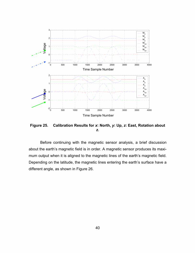
2. Results – MARG III Sensor Redesign The outcome of the calibration for a MARG III sensor is shown in Figure
25. The sensor followed pattern 1 motion. Therefore the rotation was performed
about the z-axis, with the positive x-axis originally pointing north and the positive
y-axis pointing up. The solid lines represent the raw data gathered from the sen-
sor, whereas the dashed lines represent the calibrated output.
As seen in the lower half of the figure, the x- and z-axis accelerometers
values are initially zero, as indicated by the blue solid arrow. As the x-axis starts
to tilt down, its gravity output starts to increase following a sinusoidal pattern. It
reaches its maximum value (normalized at one) when the x-axis points vertically,
away from the ground. Since the y-axis accelerometer was initially pointing up,
the minimum value of minus one was expected (green arrow). As it starts to ro-
tate toward the north (tilting toward the ground), its acceleration output value
starts to increase.
It can be clearly seen that it reaches zero at the exact moment the x-axis
accelerometer produces its maximum value. Finally, the z-axis accelerometer al-
ways produces zero values.
40
0 500 1000 1500 2000 2500 3000 3500 4000-1
0
1
2
3MxMyMzMcxMcyMcz
0 500 1000 1500 2000 2500 3000 3500 4000-2
-1
0
1
2AxAyAzAcxAcyAcz
Figure 25. Calibration Results for x: North, y: Up, z: East, Rotation about z.
Before continuing with the magnetic sensor analysis, a brief discussion
about the earth’s magnetic field is in order. A magnetic sensor produces its maxi-
mum output when it is aligned to the magnetic lines of the earth’s magnetic field.
Depending on the latitude, the magnetic lines entering the earth’s surface have a
different angle, as shown in Figure 26.
Time Sample Number
Vol
tage
V
olta
ge
Time Sample Number

41
Figure 26. Earth’s Magnetic Field Lines [From Ref. 18.].
This research took place in Monterey, California, where the latitude is
36.6o. This means that the magnetic lines enter the ground at an angle of ap-
proximately 60o. Therefore, the maximum magnetic value should be taken from a
sensor pointing toward the magnetic north (as indicated by a magnetic compass)
when the sensor is tilted to the ground at an angle of approximate 60o from the
horizontal level.
As seen in the upper half of Figure 25 (indicated by the blue dotted ar-
row), the x-axis magnetic sensor produces a negative value, even though the
sensor points to the north. As the sensor begins to tilt toward the ground, the
magnetic value decreases more and reaches its minimum value (instead of the
maximum) when the sensor points almost at 60o down. The same inconsistent
result is observed for the y-axis magnetometer (green dotted arrow).
Further testing following pattern 2 showed the same response from the z-
axis magnetic sensor. Therefore, even though the sensors seemed to be cali-
brated, they produced the opposite sense for the rotations.
The above results meant that the MARG III design, concerning the Hon-
eywell magnetic sensors, needed to be reviewed closely.

42
Further investigation showed that the design sheet that Honeywell pro-
vided for the magnetometer HMC1051Z had an erratum that indicated a reversed
polarity on the set-reset strap of the sensor. After contacting Honeywell technical
support, the erratum was confirmed [Ref. 19]. Consequently, the sensor wired as
shown on the design sheet showed a maximum magnetic field when pointing
south. This anomaly had been observed during the initial construction of the
MARG III sensor. Therefore, the set-reset straps of the x- and y-axis magnetic
sensor were wired with reverse polarity to achieve uniformity between the out-
puts of all three magnetometers. This resulted in all three magnetometers always
showing reversed magnetic fields.
By rewiring the sensors and by making a slight change to the firmware up-
loaded to all the MARGIII sensors regarding the set-reset polarity, the problem
was solved and the calibration results behaved as expected.
Since the accelerometers are designed to measure combined static (grav-
ity) and dynamic accelerations, and since the rotations were performed at a rela-
tively slow rate of 36 deg/sec, a second consideration was made about the ac-
celerometer output. According to the calibration technique, the accelerometers
should provide maximum and minimum values of positive and negative 1 g when
pointing down and up, respectively. Since the accelerometers can measure
within the range of ± 2 g, the maximum static accelerations should be only half of
the maximum value. Therefore, the possibility of dividing the accelerometer scal-
ing factors provided by the calibration sequence by a factor of 2 was considered.
The reason was to minimize the possibility of saturating the accelerometers when
sustaining the combined static and dynamic accelerations.
The results from a calibrated rotation about the x-axis, when the positive
y-axis was initially pointing down and the positive z-axis was pointing north, is
shown in Figure 27. All the calibrated data behave as expected.

43
0 500 1000 1500 2000 2500 3000-2
-1
0
1
2MxMyMzMcxMcyMcz
0 500 1000 1500 2000 2500 3000-1
-0.5
0
0.5
1
1.5
2AxAyAzAcxAcyAcz
Figure 27. Calibration Results for x: East, y: Down, z: North, Rotation about x.
C. SUMMARY
This chapter presented the firmware uploading procedure and the MARG
III sensor calibration. The test results that led to the MARG III being redesigned
were also discussed. In the following chapter, the effort of testing the CIU is ex-
amined. The QUEST algorithm as a quaternion filter is also discussed.
Time Sample Number
Vol
tage
V
olta
ge
Time Sample Number

44
THIS PAGE INTENTIONALLY LEFT BLANK

45
V. VISUALIZATION OF THE MARG III SENSOR DATA
This chapter describes the process for visualizing the MARG III data de-
livered by the CIU. The QUEST algorithm was selected to filter the data. Some
modifications were introduced to increase the accuracy of the algorithm results.
MATLAB® and SIMULINK® simulations are performed in order to validate the
response of the sensors. Finally, this chapter also presents the combined efforts
of this research and the research of another thesis [Ref. 3] to implement an X3D
based human avatar.
A. THE QUEST ALGORITHM Filtering the calibrated data requires a computationally efficient algorithm,
capable of tracking limb motion without any singularities. For this reason, the
QUEST algorithm was chosen [Ref. 20]. This algorithm was created to determine
the attitude of a rigid body in reference to a fixed coordinate system, using a set
of measurement vectors. The goal of the algorithm was to compute a rotation (at-
titude) matrix A, capable of rotating the measurement vectors (assuming no er-
rors introduced) so as to match exactly the reference vectors. Matrix A has nine
elements, which have proven to be difficult to determine [Ref. 20]. Therefore, the
QUEST algorithm was designed to compute a quaternion that describes attitude
with four elements. Once the quaternion was computed, the rotation matrix A
could be determined, and vice versa. The QUEST algorithm has been success-
fully used in the past in various applications (e.g., satellite tracking, etc.) [Ref.
20].
The MARG III sensor produces three measurement vectors every one
hundredth of a second. The magnetic vector consists of the magnetic field com-
ponents measured in the three directions x, y, and z. Similarly, the angular rate
vector holds the x, y, and z components of the angular rate measurements. Fi-
nally, the gravity vector measures the three components of the earth’s gravity
field. The minimum number of attitude measurement vectors required by the

46
QUEST algorithm to produce an output is two. The magnetic field and the gravity
vectors produced by the MARG III sensor are related to attitude. The third vector
measures rate and therefore cannot be used as an input for the QUEST algo-
rithm.
In the previous chapter, the need to acquire a set of reference vectors dur-
ing the calibration procedure was mentioned. When studying a single rigid body,
the set of these vectors can be chosen arbitrarily. On the other hand, when
studying multiple limbs linked to each other, the choice of the set of reference
vectors cannot be arbitrary. In this case, the reference vector sets should coin-
cide for all the associated limbs. Therefore, the magnetic field and gravity refer-
ence vectors should be defined with all the MARG III sensors having the same
orientation.
The algorithm requires the computation of eigenvalues of a specific matrix
K as discussed later. At the time the QUEST algorithm was first introduced in
1981, computers were not as powerful as today. For computational efficiency, the
algorithm was designed based on the acceptance that unit reference vectors and
measurements produce eigenvalues very close to one. The need for precise
computation of the eigenvalues was avoided at the expense of less accurate
quaternions. Today, computational power is not an issue. Therefore, in order to
improve the accuracy of the algorithm, the eigenvalues are computed precisely.
B. MATLAB® AND SIMULINK® SIMULATIONS As expected, the sensor measurements are contaminated by noise.
Therefore, simulations had to be done in order to evaluate the performance of
the system. For this reason, the SIMULINK® model shown in Figure 28 was cre-
ated.

47
Figure 28. The SIMULINK® Model Created to Visualize the Results.
With the use of MATLAB®, the necessary functions were created by the
author to implement the QUEST algorithm. The algorithm was implemented as
shown in Figure 29.

48
Figure 29. The Block Diagram of the QUEST Algorithm

49
The MATLAB® code is available upon request from Professor Xiaoping
Yun ([email protected]).
In the first block of the above figure, a B matrix is computed from the ref-
erence vectors v1 and v2, the measurement vectors w1 and w2 and the weighting
vector α. The weighting vector is chosen to weight the importance of the meas-
urement vectors, and its norm is equal to one. For the MARG III sensor, w1 and
w2 are the acceleration and magnetic measurements. The B matrix is used to
compute the 3 x 3 matrix S and the 3 x 1 vector Z. Then the scalars σ, κ, ∆ are
computed as shown in the above figure. Finally, the 4 x 4 matrix K is constructed
and its maximum eigenvalue is computed before calculating the scalars α, β, γ
and the 3 x 1 vector X. The vector X and the scalar γ together provide the opti-
mum quaternion that describes the attitude of the MARG III sensor.
Data from the MARG III sensors were captured and fed to the algorithm.
The sensors were performing rotations according to the two patterns, mentioned
in the previous chapter. The calibration data were loaded as MATLAB® files.
As seen in Figure 28, the computed quaternions were transformed into
Euler angles (roll φ, pitch θ and yaw ψ, indicated with the green arrow). To visu-
alize the motion captured by the MARG III sensors, a 6 degree-of-freedom (DOF)
missile provided by SIMULINK® was used (red arrow in Figure 28), as shown in
Figure 30.
The results showed that the algorithm responded well. The missile fol-
lowed the patterned rotations very closely. The Euler angles for a rotation follow-
ing pattern 2 are presented in Figure 31.
The missile was expected to perform a 720o rotation (roll φ) about its lon-
gitudinal axis. No pitch or yaw motions were expected to appear. The corre-
sponding motion of the missile was an exact 720o rotation about x-axis. Figure
31 shows that the missile starts with a zero roll. When the motion starts, the mis-
sile responds with a linear rotation toward negative 180o. The system measures
angles within the range of negative 180o and positive 180o. Therefore, a sudden

50
transition from negative 180o to positive 180o appears in Figure 31. In reality, the
missile continuous to rotate with a constant angular rate until it performs a full
720o rotation and then it stops. A slight pitch deviation and an even smaller yaw
deviation, possibly due to imperfections in the calibration, are also noticed in
Figure 31.
Figure 30. The SIMULINK® Rigid Body Missile.
500 1000 1500 2000 2500
-100
0
100Roll φ
500 1000 1500 2000 2500
-100
0
100Pitch θ
500 1000 1500 2000 2500
-100
0
100Yaw ψ
Figure 31. Euler Angles for a Pattern 2 Motion.

51
C. REAL-TIME VISUALIZATION OF THE SENSOR DATA Since the MATLAB® simulation results were satisfactory, real-time testing
was performed next. Another thesis focusing on the development of an X3D ava-
tar [Ref. 3] was conducted simultaneously. In that effort the QUEST algorithm
was implemented in JAVA along with server-client programs capable of acquiring
the MARG III data of this thesis from the CIU in real time. Wireless IEEE 802.11b
communication was established in an effort to detach the tracked body from the
rest of the hardware involved.
After the calibration, the sensor data were filtered, and the resulting opti-
mal quaternions were transformed into axis-angle pairs by a client program. This
transformation was necessary since the avatar was created in VRML language
(X3D Graphics Specification), which has been standardized to use axis-angle
pairs to represent rotations [Ref. 21].
The avatar was created in two stages. First, a human left arm was de-
signed as shown in Figure 32. After all the tests were performed successfully
with the one-arm avatar, the whole human body was introduced. The final ver-
sion of the human avatar is shown in Figure 33.

52
Figure 32. Left Lower Arm Avatar Created in X3D Format.
Figure 33. The X3D Human Avatar.

53
When the avatar is in a resting position, all the limbs are initially aligned
with a coordinate system as shown in Figure 33. It can be seen that the z-axis
extends from the front of the body, the y-axis is pointing up and the x-axis is
pointing to the left of the avatar.
The MARG III sensors measure the attitude of the limbs in reference to a
fixed coordinate system, as mentioned earlier in this chapter. In order to achieve
coincidence between the attitude measured by the sensors and the one repre-
sented by the human avatar, these reference vectors should be captured with the
sensors oriented identically to the avatar. This means that the sensor’s z-axis
must be parallel to the ground, and the positive y-axis should be vertical to the
ground and facing up. The x-axis should be placed consequently. As long as this
constraint holds, it does not matter what the azimuthal orientation of the MARG
III sensors is at the starting position, since the avatar has relative azimuthal feel-
ing only, and not absolute. Therefore, if all sensors have their positive z-axis ori-
ented to a constant point on the horizon (e.g., north), the reference vectors cap-
tured will coincide with the avatar’s coordinate system. For the purposes of this
thesis, the reference azimuthal orientation was chosen to be with the positive z-
axis pointing to magnetic north, as described in Chapter IV.
The testing results with the full-body avatar were very successful. With the
use of two MARG III sensors, the avatar followed the motion of the human right
arm exactly. Figure 34 and Figure 35 show snapshots, in which the user has two
MARG III sensors attached to his right arm. The user moves his arm, and the
motion is followed in real time by the avatar. If a fast motion is performed, the
system loses the accuracy during the transition. This occurs because fast mo-
tions introduce high dynamic accelerations that contaminate the gravity field
measurements. Furthermore, when the accelerometers exceed their maximum
measurement range (± 2 g), they saturate, and the QUEST algorithm produces
inaccurate quaternions. Nevertheless, when the arm reaches its final position,
the system resumes its accuracy, and the represented limb attitude becomes
precise (steady-state response).

54
Figure 34. Real-time Projection of a Human Arm Motion Using Two MARG III Sensors.
Figure 35. Real-time Projection of a Human Arm Motion Using Two MARG III Sensors.

55
When the rate sensor measurements are combined with the QUEST algo-
rithm using a Kalman filter, the system performance is expected to improve dur-
ing the transition motions [Ref. 22].
D. SUMMARY
The efforts to verify the functionality of the MARG III sensor and the CIU
were discussed in this chapter. The QUEST algorithm was chosen to filter the
data delivered by the CIU. Visual representation was first achieved by using a
SIMULINK® model. Finally, combined efforts of this research and the research of
another thesis [Ref. 3] led to the design of an X3D human avatar visualizing the
motion of a tracked human body in real time.

56
THIS PAGE INTENTIONALLY LEFT BLANK

57
VI. CONCLUSIONS AND FURTHER WORK
A. THESIS CONTRIBUTIONS This thesis has developed a system for tracking the motion of a human
body by the use of the MARG III sensors. The system uses data provided by the
sensors to achieve the immersion into a Virtual Environment.
The main components of the system, other than the MARG III sensors,
are the Control Interface Unit (CUI), the Wiser 2400 serial-to-wireless transmitter,
and a server capable of filtering the data delivered by the CIU. Clients can con-
nect to the server at any time and provide a real-time visual representation of the
human motion.
The digital data from the MARG III sensors are parsed into 12-bit words
and are transmitted through an SPI connection to the CIU. The CIU sends the
data through an RS-232 connection to the serial-to-wireless transmitter. Then,
the data are filtered and transformed into quaternions with the use of the QUEST
algorithm. Finally, the quaternions are converted into axis-angle pairs, which are
used by an X3D human avatar designed to project the 3-DOF motion of a human
body on a computer screen.
The heart of this system and the main component studied in this thesis is
the CIU. At this moment, it is capable of receiving data from three MARG III sen-
sors and of preparing them to be transmitted wirelessly through Wiser 2400
transmitters at a speed of 19.2 kbps for each MARG III sensor. The CIU is also
capable of providing the MARG III sensors with the necessary power to operate,
and it also synchronizes the SPI communication by providing the clock. It was
developed in two stages. The first stage involved the design and implementation
of a one-channel CIU facilitating the testing and evaluating of a single MARG III
sensor. Then the three-channel CIU (three one-channel CIUs in a parallel con-
figuration), capable of transmitting data from three MARG III sensors, was im-
plemented and tested successfully.

58
The QUEST algorithm is used to filter the measurement data. It represents
the human body motion in the form of quaternions. It uses the accelerometer and
magnetometer measurements provided by the MARG III sensor to compute the
attitude of the rigid body in reference to a constant set of vectors with no singu-
larities. The QUEST algorithm is also very efficient for low frequency motions but
quite inaccurate for fast moving limbs.
Finally, the MARG III sensor is designed to be small and energy efficient
due to the characteristics of its components. It provides real-time tracking meas-
urements sampled at a rate of 100 Hz, which has proven to be sufficient. The
measurements are provided by three magnetometers, three accelerometers and
three rate sensors in the MARG III sensor forming an orthogonal triad.
B. FURTHER DEVELOPMENT The three-channel CIU is capable of transmitting data from three MARG III
sensors without performing any multiplexing. Each MARG III sensor has its data
transmitted wirelessly to the server through an independent thread. This involves
using three different Wiser 2400 transmitters. To overcome the problem of using
multiple transmitters, the sixteen-channel CIU was designed. At the time of this
writing, it is approaching its final steps of development. The new CIU will be ca-
pable of receiving data from sixteen sensors simultaneously with a sampling rate
of 100 Hz, multiplexing them, and transmitting them through a wireless connec-
tion. Issues involving the high data-transmission rate of 232 kbps needed to
achieve transmission from all the MARG III sensors (including the overhead) will
have to be solved.
A complementary filter is needed to supplement the existing QUEST algo-
rithm. The new filter should receive the quaternions produced by the QUEST al-
gorithm and filter them along with the measurements delivered from the rate sen-
sors. Issues involving the bias introduced by the accelerometers from measuring
the combination of dynamic and static accelerations must be solved (by low-pass

59
filtering). Drifting of the output, introduced by the inability of the rate sensors to
track low frequencies (slow motion) accurately, must be removed (high-pass fil-
tering).
As technology evolves, the MARG sensor can be upgraded. The next
generation of MARG sensors, called the MARG IV, is currently under develop-
ment. With even smaller components, it is expected that the future design of
MARG sensors could even be sewed on fabric.
The current system tracks a slow moving human body accurately. All the
experimental results have indicated that after the development of the sixteen-
channel CIU and the complementary filter, the system will be capable of tracking
fifteen human limbs accurately. Visual representation and thus immersion into
the Virtual Environment can be achieved without any of the limitations that the
MARG II sensors introduced. The 100-Hz sampling rate has proved sufficient for
real-time tracking of a human body motion. Implementing the system for immer-
sion of more than one user into the same Virtual Environment is possible.

60
THIS PAGE INTENTIONALLY LEFT BLANK

61
LIST OF REFERENCES
1. Synthetic Environment Laboratory, Synthetic Environments, [http://www.sel.bee.qut.edu.au/understand/understand.htm], last accessed January 2004.
2. Eric R. Bachmann, “Inertial and Magnetic Tracking of Limb Segment Ori-
entation for Inserting Humans into Synthetic Environments,” Ph.D. Disser-tation, Naval Postgraduate School, Monterey, CA, December 2000.
3. Faruk Yildiz, “Implementation of Human Avatars for the MARG Project in
Networked Virtual Environments,” MS Thesis, Naval Postgraduate School, Monterey, CA, March 2004.
4. J. Bers, “A Model Server for Human Motion Capture and Representation,”
Presence: Teleoperators and Virtual Environments, Vol. 5, No. 4, MIT Press, Cambridge MA, pp. 381-392, Fall 1996.
5. Honeywell Inc., Honeywell 1, 2, and 3-axis Magnetic Sensors, HMC1051 /
HMC1052 / HMC1053, October 2003, Rev. -, [http://www.ssec.honeywell.com/magnetic/datasheets/HMC105X.pdf], last accessed February 2004.
6. Analog Devices Inc., Analog Devices ADXL202E Low-Cost ± 2 g Dual-
Axis Accelerometer with Duty Cycle Output, 2000, Rev. A, [http://www.analog.com/UploadedFiles/Data_Sheets/567227477ADXL202E_a.pdf], last accessed February 2004.
7. Analog Devices Inc., Analog Devices ADXL202E image,
[http://www.analog.com/productSelection/images/ADXL202E_cerpak_vs_penny.jpg], last accessed February 2004.
8. NEC TOKIN Corporation, NEC TOKIN Sensors, September 2000, Vol. 03,
Rev. 2003, pp. 23-24, [http://www.nec-tokin.com/english/product/pdf_dl/sensors.pdf], last accessed February 2004.

62
9. Eric R. Bachmann, Xiaoping Yun, Doug McKinney, Robert B. McGhee, and Michael J. Zyda, “Design and Implementation of MARG Sensors for 3-DOF Orientation Measurement of Rigid Bodies,” Proceedings of the 2003 IEEE International Conference on Robotics and Automation (ICRA 2003), Taipei, Taiwan, pp. 1171-1178, September 14–19, 2003.
10. Texas Instruments Incorporated, MSP430F149 Product Information,1995-
2003, [http://focus.ti.com/docs/prod/folders/print/msp430f149.html], last accessed January 2004.
11. Texas Instruments Incorporated, Texas Instruments MSP430x13x,
MSP430x14x, MSP430x14x1 Mixed Signal Microcontroller Datasheet, July 2000, Rev E, August 2003, [http://focus.ti.com/lit/ds/symlink/msp430f149.pdf], last accessed January 2004.
12. OTC Wireless Inc, WiSER 2400 802.11b Wireless Serial Port Adapter
User Guider, Version 1.01, 2001, [http://www.otcwireless.com/support/downloads/wiser/Wiser9600/WiSER2400UG.pdf], last accessed February 2004.
13. MAXIM Integrated Products, MAX3238* +3.0V to +5.5V, 1µA, up to
250kbps, True RS-232 Transceiver with AutoShutdown Plus, Rev 1, 10/02, [http://pdfserv.maxim-ic.com/en/ds/MAX3238.pdf], last accessed February 2004.
14. Doug McKinney, MARG III Command and Control Diagram, Rev. B,
McKinney Technology, Chandler, AZ, 08 December 2003. 15. XILINX Inc., Spartan-II 2.5V FPGA Family: Complete Data Sheet,3 Sep-
tember 2003, [http://www.xilinx.com/bvdocs/publications/ds001.pdf], last accessed February 2004.
16. Webopedia Online Encyclopedia,
[http://www.webopedia.com/TERM/A/ASIC.html], last accessed February 2004.
17. Sander Electronic, Starterkits für MSP430-Controller: MSP-FET-430, Oc-
tober 2003, [http://www.sander-electronic.de/es0004.html], last accessed February 2004.

63
18. Michael J. Caruso, Applications of Magnetoresistive Sensors in Navigation Systems, Honeywell Inc., February 1998, [http://www.ssec.honeywell.com/magnetic/datasheets/sae.pdf], last ac-cessed February 2004.
19. Doug McKinney in email communication, McKinney Technology, Chan-
dler, AZ, 14 November 2003. 20. M. D. Schuster and S.D. Oh, “Three-Axis Attitude Determination from Vec-
tor Observations,” Journal of Guidance and Control, Vol. 4, No. 1, pp. 70-77, January-February, 1981.
21. Andreas Jochheim, Michael Gerke, and Andreas Bischoff, Modeling and
Simulation of Robotic Systems, Frame Transformations in VRML, Control Systems Engineering group, Department of Electrical Engineering, Uni-versity of Hagen, Version 3.0, 17 August 200, [http://icosym-nt.cvut.cz/odl/partners/fuh/course_main/node36.html,] last accessed Feb-ruary 2004.
22. Xiaoping Yun, Mariano Lizarraga, Eric R. Bachmann and Robert B.
McGhee, "An Improved Quaternion-Based Kalman Filter for Real-Time Tracking of Rigid Body Orientations,” Proceedings of Intelligent Robots and Systems, Las Vegas, NV, pp. 1074-1079, October 2003.

64
THIS PAGE INTENTIONALLY LEFT BLANK

65
INITIAL DISTRIBUTION LIST
1. Defense Technical Information Center Ft. Belvoir, Virginia
2. Dudley Knox Library Naval Postgraduate School Monterey, California
3. Chairman Code EC Department of Electrical and Computer Engineering Naval Postgraduate School Monterey, California
4. Chairman Code IS Department of Information Science Naval Postgraduate School Monterey, California
5. Professor Xiaoping Yun, Code EC/Yx
Department of Electrical and Computer Engineering Naval Postgraduate School Monterey, California
6. Professor David C. Jenn, Code EC/Jn Department of Electrical and Computer Engineering Monterey, California
7. Professor Eric R. Bachmann Department of Computer Science and System Analysis Miami University Oxford, Ohio
8. Professor Robert B. McGhee
Department of Computer Science, Code CS/Mz Monterey, California
9. Doug McKinney President McKinney Technology Chandler, Arizona

66
10. Andreas Kavousanos-Kavousanakis Athens, Greece
11. Faruk Yildiz Gazipasa/Antalya Turkey